

Page 1

Total solder points: 82
Difficulty level: beginner 1 2 3 4 5 advanced
2 MODULAR DIGITS WITH SERIAL INTERFACE
K8063
y
s
a
e
n
a
n
i
d
e
k
n
i
l
l
p
i
t
l
u
M
a
w
S
ILLUSTRATED ASSEMBLY MANUAL H8063IP-1
e
r
c
o
t
y
k
-
e
r
o
c
r
a
l
e
t
a
g
n
i
p
e
e
a
e
r
r
e
g
g
n
i
m
i
t
,
s
t
i
n
u
e
s
t
u
o
d
t
n
u
o
c
,
e
b
n
a
c
.
g
.
e
r
o
f
.
.
.
,
g
n
i
Page 2

Features & Specifications
The K8063 is a 7-segment display which can be controlled by a two-wire serial connection, using the RS232 protocol. The
protocol is platform-independent i.e. any computer running any programming language can control the K8063, as long as it
is equipped with a serial port. Up to 255 units can be individually addressed, allowing you to create large display systems for
e.g. scoreboards, clocks, timers, thermometers, games, …
Features
Red bright 57mm jumbo 7-segment display
Complete with snap-in enclosu re
Multiple units can easily be linked in order to create larger readouts for different purposes e.g. scorekeeping, timing,
counting, ...
Easy platform-independent control via three-wire RS232 interface
Up to 255 separate units can be addressed
Tested with distances of up to 50m between PC and display
Use our optional PCUSB6 for USB connection
Specifications
Power supply: 9 to 12Vdc / 120mA per display
RS232 interface: 2400baud / 8databits / no parity / 1 stop bit
Dimensions: 74 x 58.5 x 32mm
The general manuals containing guidelines for assembly, safety and electromagnetic compatibility can be downloaded
from our Velleman website (support / manuals / HALG).
2
Page 3
Assembly hints
0
.
0
0
0
1. Assembly (Skipping this can lead to troubles ! )
Ok, so we have your attention. These hints will help you to make this project successful. Read them carefully.
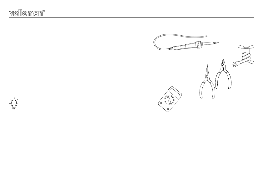
1.1 Make sure you have the right tools:
• A good quality soldering iron (25-40W) with a small tip.
• Wipe it often on a wet sponge o r c loth , to ke ep it c lean ; th en apply so lder to th e t ip, to g ive it a wet look. This is called ‘thinn ing’ an d w ill
protect the tip, an d enab les you t o make good conn ections. When so lder ro lls of f th e tip, it ne eds clean ing.
• Thin raisin-core solder. Do not use any flux or grease.
• A diagonal cutter to trim excess wires. To avoid in jury wh en cutting ex cess leads, ho ld the lead so th ey
cannot fly towards the eyes.
• Needle nose pliers, for bending leads, or to hold components in place.
• Small blade and Phillips screwdrivers. A basic range is fine.
For some projects, a basic multi-meter is required, or might be handy
1.2 Assembly Hints :
⇒ Make sure the skill level matches your experience, to avoid disappointments.
⇒ Follow the instructions carefully. Read and understand the entire step before you perform each operation.
⇒ Perform the assembly in the correct order as stated in this manual
⇒ Position all parts on the PCB (Printed Circuit Board) as shown on the drawings.
⇒ Values on the circuit diagram are subject to changes.
⇒ Values in this assembly guide are correct*
⇒ Use the check-boxes to mark your progress.
⇒ Please read the included information on safety and customer service
* Typographical inaccuracies excluded. Always look for poss ible last m inu te manu al updates, indicated as ‘NOTE ’ on a separate leaflet.
3
Page 4
Assembly hints
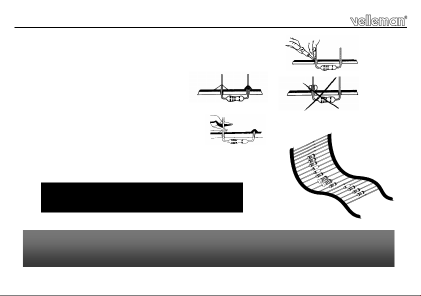
1.3 Soldering Hints :
1- Mount the component against the PCB surface and carefully solder the leads
2- Make sure the solder joints are cone-shaped and shiny
3- Trim excess leads as close as possible to the solder joint
REMOVE THEM FROM THE TAPE ONE AT A TIME !
AXIAL COMPONENTS ARE TAPED IN THE
CORRECT MOUNTING SEQUENCE !
You will find the colour code for the resistances and the LEDs in the HALG
(general manual) and on our website: http://www.velleman.be/common/service.aspx
4
Page 5
Construction
Remark: all components are supplied in a double quantity to allow the assembly of 2 digits. Repeat the
procedure of the first digit to assemble the second one.
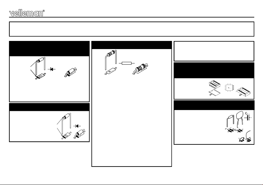
1. Zener diodes. Watch the
CATHODE
ZD...
CATHODE
D...
polarity !
ZD1 : 5V1
ZD2 : 5V1
ZD3 : 4V3
2. Diode. Watch the polarity !
D1 : 1N4007
3. Resistors
R1 : 560 (5 - 6 - 1 - B)
R2 : 560 (5 - 6 - 1 - B)
Mount R2 at end of chain !
R...
For example: when linking 4
digits, mount the resistor R2 on
the last (4
space open on the other 3 digits.
R3 : 10K (1 - 0 - 3 - B)
R4 : 1K (1 - 0 - 2 - B)
R5 : 100 (1 - 0 - 1 - B)
R6 : 100 (1 - 0 - 1 - B)
R7 : 100 (1 - 0 - 1 - B)
R8 : 100 (1 - 0 - 1 - B)
R9 : 100 (1 - 0 - 1 - B)
R10 : 100 (1 - 0 - 1 - B)
th
) digit and leave its
R11 : 100 (1 - 0 - 1 - B)
R12 : 100 (1 - 0 - 1 - B)
R13 : 100K (1 - 0 - 4 - B)
4. IC so cket . W a tc h t he
position of the notch!
IC1 : 14p
5. Capacitors
C1 : 100nF (104)
C2 : 100nF (104)
C3 : 100nF (104)
5
Page 6
Construction
M3 NUT
VOLTAGE REGULATOR
PCB
M3 BOLT
VR...
I O
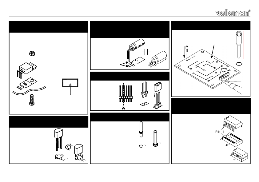
6. Voltage regulator
VR1 : UA7809
7. Transistor.
T1 : BC547B
6
8. Electrolytic Capacitors.
Watch the polarity !
C4 : 100µF
C5 : 100µF
+
9. Pin header
SK7 :
2p
10. PCB tabs
RS232 (2x)
+ (2x)
GND (2x)
Remark: on the outer digits, only the
PCB tabs close to the IC have to be
mounted.
C...
11. Tulip pin headers
10x
Solder side
WATCH FOR SHOR TS !
12. IC. Watch the position of
the notch!
IC1 : VK8063
Programmed PIC16 F630
Page 7

13. Assembly
Construction
2nd digit 1st digit
Mount the spacers onto the PCB with the 2 included screws and install the digit display on the
solder side of the PCB. Pay attention to the position of the decimal point, see figure 1.0.
Fig 1.0
Then turn the PCB around and place it into the housing with the display
towards the front, see figure 2.0.
Fig 2.0
7
Page 8

Construction
If you want to mount the digit(s) on the wall, finish by mounting the brackets on the PCB, see figure 3.0
Parker screw
2,9 x 12,7mm
Fig 3.0
8
Page 9

Test
14. Test
When the assembly has been completed, we recommended to test each
individual unit before daisy-chaining them. Make sure SK7 (address jumper) is
put in place, see figure 4.0.
Connect a 9 to 12VDC power supply to the pins GND and +V.
At power-on, the K8063 will display .0123456789 (segment test).
Next, it will display its current address (default : 1) for a couple of seconds.
At this time, the K8063 allows you to select an address ranging from 0 to 19*.
Simply wait until the desired address is displayed and remove the SK7
address jumper. ( note : addresses 0 to 9 are displayed as 0 to 9, addresses
10 to 19 are displayed as 0. to 9. (note the dot).
The K8063 will loop the addresses until the jumper is removed, so if you have missed the desired address,
you can wait a while and it will appear again.
Once you have removed the jumper, the K8063 stops looping and after a couple of seconds the display will
turn blank. The selected address is now stored in its memory.
Fig 4.0
*If you require 20 or more different addresses, you can configure them when the K8063 units are hooked-up
to the computer (see further in this manual).
9
Page 10

Hook-up
Female 9P SUBD connector
To serial port
1
5
15. Hook-up
Hook-up : All units have two sets of connectors. This allows you to hook them up in an easy way, as
shown below (fig. 5.0):
To pin 2 & 3
10
‘+’ supply
‘-’ supply
1
To pin 5
2
Fig 5.0
n
Page 11

Hook-up
Power supply : The K8063 re quires a 9 to 12V DC power s uppl y. Powe r consum ption i s 120mA max. pe r unit
(12V) (e.g. if y o u h ave 5 u nits , yo u ne ed a p owe r s upp l y ca pa bl e of de l iv eri ng at le ast 5x1 2 0 = 60 0m A ). N ote : If
the total # of displays exceeds 6, it is required t o wire the unit s according to the drawi ng below, as the PCB tracks
are unable to handle the large currents that flow when more than 6 units are operated simultaneously.
Furthermore, if more than 15 units are operated at the same time, we recommend to use a separate power supply
for every group of 15 d ig i ts, to a v o id l arge currents a nd to avoid the n eed for heavy w ir in g. (Fig 6.0).
RS232
+V
GND
Fig 6.0
Serial port specifi cations : The K8063 can be hooked up to any serial port which supports the RS232 standard
(e.g. PC COM port). Serial port settings are 2400/8/n/1 (2400 baud, 8 databits, no parity, 1 stopbit).
11
Page 12

Hook-up
Serial port connection : Connect the pin marked ‘RS232’ to pins 2&3 of the 9P SUBD connector.
Connect the pin marked ‘GND’ to pin 5 of the 9P SUBD connector. We have successfully bridged up to
50m between the serial port and the last digit, using standard UTP (twisted pair) cable. Make sure to
remove resistor R2 (terminator) from all K8063 units except the last unit (unit n in the example above).
Controlling one or more K8063 via a computer:
In order to display information on the K8063, you need to send it a correct data string. The data string
consists of 5 bytes :
Byte 1 : chr$(13)
(letting the K8063 know that data will come in)
Byte 2 : address (0 to 255)
(determines the individual K8063 you want to access. Note: Address ‘0’ accesses all connected K8063)
Byte3 : command
(A # of commands are available, to control the various functions of the K8063, see list of commands)
Byte4 : parameter
(Most commands require a parameter. See list of commands)
Byte5 : checksum
Two-compliment of the sum of the previous 4 bytes
256 - (Byte1+ Byte2 + Byte3 + Byte4) MOD 256
12
Page 13

Hook-up
Available commands:
Command
Description Parameter
‘E’ Emergency stop Don’t care (anything goes)
‘D’ Display address on all digits Don’t care
‘B’ Byte-command 0..255 (see drawing)
‘S’ Strobe command Don’t care
‘C’ Change address 0..255 (new address)
‘R’ Reset all displays Don’t care
‘F’ Force address Don’t care
‘A’ Send ASCII 32,48..57 (blank, 0..9)
‘P’ Decimal point 0 or 255 (OFF / ON)
‘I’ Intensity control 0 or 255 (BRIGHT / DIM)
‘E’ : Emergency stop. All displays are blanked, regardless of address.
(Hint : execute the ‘Strobe’ command to restore all displays)
‘D’ : Display address all digits. All digits show their address. Addresses between 0 and 9 are displ ayed
as 0 to 9
Addresses between 10 and 19 are displayed as 0. to 9. (See earlier). Addresses between 20 and 255
are displayed in a binary fashion (see drawing).
13
Page 14

Hook-up
‘B’ : Allows you to turn on individual segments. Parameter = sum of the values of the individual segments
(see drawing 7.0) (e.g. 7 = 32+4+8= 44).
‘S’ : Strobe command. After executing a ‘B’,‘A’ or ‘P’ –command, the displays are not updated, you need to
execute the ‘S’-command. By doing this, all displays are updated at the same time.
‘C’ : Change address. Allows you to change the address of an individual K 8063. Put jumper SK7 in place
on each K8063 which needs to respond to the ‘change address’-command. When the command has been
executed, the new address is displayed. Remove the jumper(s).
‘R’ : In the unlikely event of strange behavior of one or more displays, you can reset all displays at once by
executing this command.
14
1
64
8.
128
32
2
4
Fig 7.0
8
16
Page 15

Hook-up
‘F’ : Force all displays to address ‘1’ (return to factory settings).
‘A’ : Send ASCII to display. An easy way of displaying figures 0 to 9
Simply send their ASCII value. ( 32ascii blanks the display, 0 = 48ascii, 9 = 57ascii).
‘P’ : Decimal point control. Parameter 255 turns the decimal point on, parameter 0 turns it off. Decimal
point remains on until it has been forced off.
‘I’ : Brightness control. Parameter 255 set the display to ‘dim’, parameter 0 sets the display to ‘bri ght’.
Remark : For best results, we recommend to send the command string at least three times a row. When the
brightness is set to dim, it is recommended to send the string at least 4 times to make sure all displays are
updated.
Furthermore, we recommend a delay of at least 100ms between sending a command and sending the
‘Strobe’-command.
15
Page 16

Hook-up
Command string examples :
EX1: To reset all displays : Execute the ‘R’-command
Data to be sent to serial port :
Chr$(13) (Init command)
Chr$(8) (Don’t care)
Chr$(82) “R” = Reset command
Chr$(1) (Don’t care)
Chr$(152) (Checksum : 2-complime n t of th e sum of the 4 previou s bytes)
EX2: To display a ‘0’ on all units with address ‘1’ : Execute the ‘A’-command and supply address ‘1’.
Next, execute the ‘S’ (strobe) command.
Data to be sent to serial port :
Chr$(13) (Init command)
Chr$(1) (Address 1)
Chr$(65) “A” = ASCII command
Chr$(48) (ASCII value of zero = 48)
Chr$(129) (Checksum : 2-complime n t of the sum of the 4 pre v i o u s by tes)
100ms pause
Chr$(13) (Init command)
Chr$(8) (Don’t care)
Chr$(83) “S” = strobe command
Chr$(1) (Don’t care)
Chr$(151) (Checksum : 2-complime n t of th e sum of the 4 previou s bytes)
16
Page 17

Hook-up
EX3: To turn on all segments on all units with address ‘1’ : Execute the ‘B’-command and supply address
‘1’. Next, execute the ‘S’ (strobe) command.
Data to be sent to serial port :
Chr$(13) (Init command)
Chr$(1) (Address 1)
Chr$(66) “B” = Byte command
Chr$(255) (255 = sum of segments)
Chr$(177) (Checksum : 2-complime n t of th e sum of the 4 previou s by tes)
100ms pause
Chr$(13) (Init command)
Chr$(8) (Don’t care)
Chr$(83) “S” = strobe command
Chr$(1) (Don’t care)
Chr$(151) (Checksum : 2-complime n t of th e sum of the 4 previou s by tes)
Note : Our website www.velleman.be features some example programs written in VB6 which
can be used as a guide for writing your own software (source code is supplied).
17
Page 18

PCB
16. PCB
18
Page 19

17. Diagram
Diagram
SK1
SK2
SK3
SK4
D1
1N4007
+
-
GND GND
SK5
RS232
SK6
Place termi n at or
at end of chain
only
GND
C4
C1
100n
100µ
GND GND
GND
R3
10K
R2
560
GND
VR1
UA7809
I O
GND
+5V
R4
1K
ZD2
5V1
GND
SK7
Address set
JP2
T1
BC547
+5V
GND
R13
100K
C2
100n
12
11
4
2
+5V
C3
100n
1
GND
IC1
RB3/MCLR/Vpp
RB5/OSC1/CLKIN
RB1
RB2
RB4/OSC2/CLKOUT
VSS
14
GND
R1
560
ZD1
5V1
GND
VDD
RC5/T0CKI
PIC16C630
RB0
RC3
RC2
RC1
RC0
RC4
GND
C5
100µ
13
7
8
9
10
5
6
3
R5
R6
R7
R8
R9
R10
R11
R12
100
100
100
100
100
100
100
100
ZD3
4V7
4V3
7
6
4
3
2
9
10
8
a
b
c
d
e
f
g
DP
DY1
A-2301SR
5
A1A
19
Page 20

VELLEMAN Components NV
www.velleman-kit.com
Modifications and typographical errors reserved
© Velleman Components nv.
H8063IP - 2004 - ED1 (rev 4)
Legen Heirweg 33
9890 Gavere
Belgium Europe
www.velleman.be
5 410329 318802
 Loading...