

Page 1
Total solder points: 91
Difficulty level: beginner 1 2 3 4 5 advanc ed
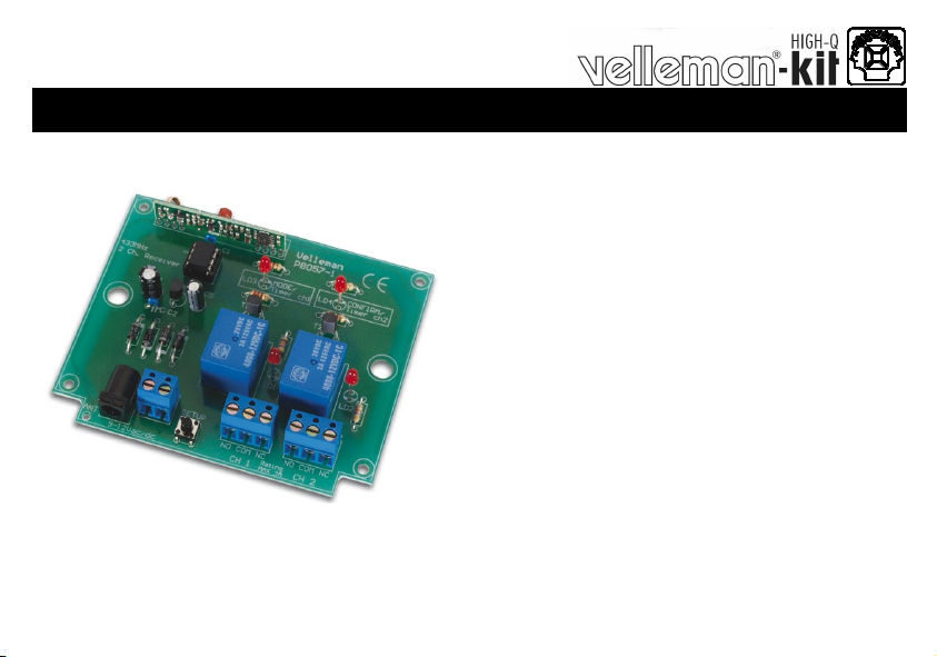
2 CHANNEL RF RECEIVER
K8057
8
0
1
M
V
/
9
5
0
8
K
h
t
i
w
e
s
u
r
o
F
a
h
C
2
Specifications
Power supply : 9 to 12V AC or DC / 1 00mA max.
Relay contacts NO / NC: 3A each.
Selectable timers per output
Open field range of up to 30m possible.
On board antenna or external antenna.
Dimensions : 100 x 82mm.
ILLUSTRATED ASSEMBLY MANUAL H8057IP-1
R
l
e
n
n
s
n
a
r
t
F
m
r
e
t
t
i
Page 2
Assembly hints
0
.
0
0
0
1. Assembly (Skipping this can lead to troubles ! )
Ok, so we have your attention. These hints will help you to make this project successful. Read them carefully.
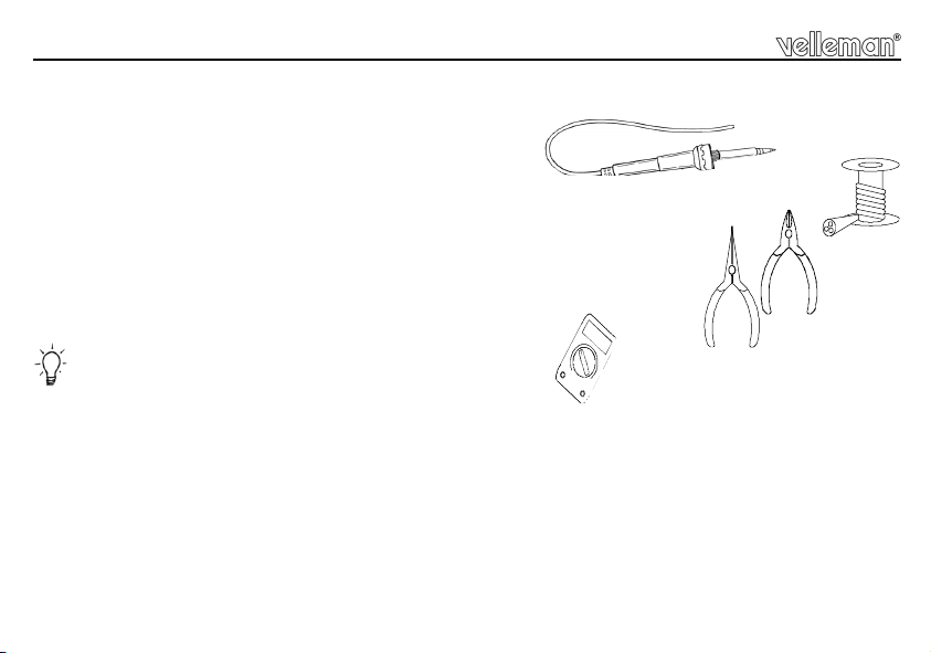
1.1 Make sure you have the right tools:
• A good quality soldering iron (25-40W) with a small tip.
• Wipe it often on a wet sponge or cloth, to keep it clean; then apply solder to the tip, to give it a wet look. This is called ‘thinning’ and will
protect the tip, and enables you to make good connections. When solder rolls off the tip, it needs cleaning.
• Thin raisin-core solder. Do not use any flux or grease.
• A diagonal cutter to t rim exc ess wires. To avoi d injury when cutting excess l eads, ho ld the le ad so they
cannot fly towards the eyes.
• Needle nose pliers, for bending leads, or to hold components in place.
• Small blade and Phillips screwdrivers. A basic range is fine.
For some projects, a basic multi-meter is required, or might be handy
1.2 Assembly Hints :
⇒ Make sure the skill level matches your experience, to avoid disappointments.
⇒ Follow the instructions carefully. Read and understand the entire step before you perform each operation.
⇒ Perform the assembly in the correct order as stated in this manual
⇒ Position all parts on the PCB (Printed Circuit Board) as shown on the drawings.
⇒ Values on the circuit diagram are subject to changes.
⇒ Values in this assembly guide are correct*
⇒ Use the check-boxes to mark your progress.
⇒ Please read the included information on safety and customer service
* Typograp hical inac curacies excluded. Al ways look for possible last mi nute manual upda tes, indic ated as ‘NOTE’ on a s eparat e leaflet.
2
Page 3
Assembly hints
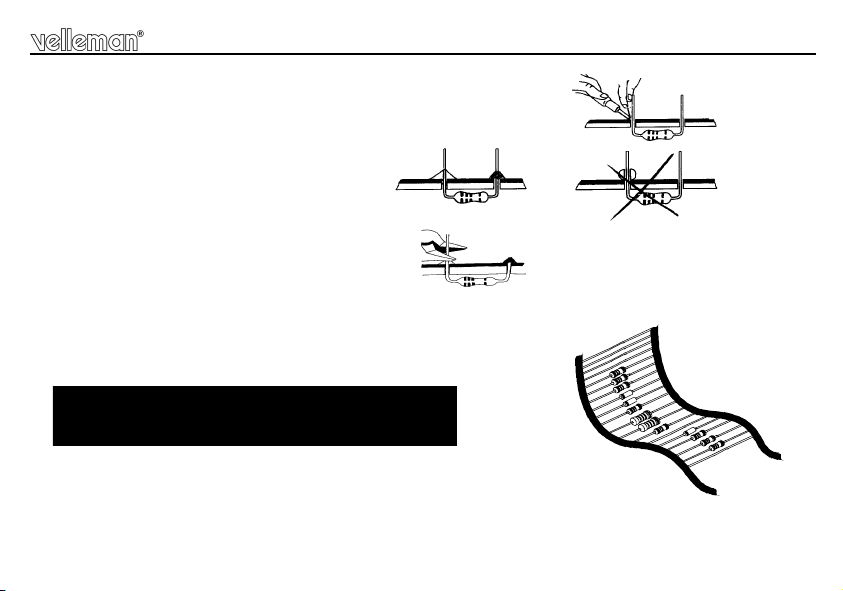
1.3 Soldering Hints :
1- Mount the component against the PCB surface and carefully solder the leads
2- Make sure the solder joints are cone-shaped and shiny
3- Trim excess leads as close as possible to the solder joint
REMOVE THEM FROM THE TAPE ONE AT A TIME !
AXIAL COMPONENTS ARE TAPED IN THE
CORRECT MOUNTING SEQUENCE !
3
Page 4

Construction / Bouw / Montage / Montaje
SW...
1. Diodes / Diode / Diodo
D1 : 1N4148
D2 : 1N4148
D3 : 1N4007
D4 : 1N4007
D5 : 1N4007
D6 : 1N4007
Watch the polar ity! - Let op de p olariteit !
Attention à la polarité! - Achten Sie auf
die Polari tät! - ¡Controle l a polaridad !
CATHODE
2. Resistors / Weerstanden /
Résistances / Widerstände /
Resistencias
R1 : 330 (3 - 3 - 1 - B)
R2 : 330 (3 - 3 - 1 - B)
R3 : 330 (3 - 3 - 1 - B)
R4 : 330 (3 - 3 - 1 - B)
R5 : 47K (4 - 7 - 3 - B)
R6 : 47K (4 - 7 - 3 - B)
4
R...
3. IC socket / IC voetje / support
de CI / IC-Fassung / Zócalo de
integrado
D...
IC1 : 8p
Pay attention of the notch !
Let op de positie van de nok!
Attention à la position de l’e ncoche!
Achten Sie auf des position des Nockens!
¡Atención a la posición del la muesca!
4. Capacitors / Konden satoren /
Condensateurs / Kondensatoren / Condensadores
C1 : 100nF (104)
C2 : 100nF (104)
5. Transistor
T1 : BC547B
T2 : BC547B
6. Voltage regulator / Spanningsregelaar / Régulateur de tension /
Spannungsregler / Regulador de
tensión
VR1 : UA78L05
VR...
7. Push button / Drukknop /
bouton-poussoir /
Druckknöpfe / Pulsador
SW1 : KRS0610
8. DC-jack / DC connector /
Connecteur CC / DC Einbaubuchse / Conector CC
SK1
SK...
+
SW
-
Page 5

Construction / Bouw / Montage / Montaje
9. Receiver module / Ontvangstmodule / Module récepteur /
Empfängermodul / Módulo de
recepción
RX1 : 433MHz.
!
10. Screw terminal / schroefconnectoren / connecteurs à
visser / Schraubconnectoren /
Regletas de conexión
SK2 : 2p.
SK3 : 3p.
SK4 : 3p.
11. Electrolytic Capacitors /
Electrolytische condensatoren /
Condensateurs électrolytiques /
Elektrolytkondensatoren / Condensadores electr olítico s
C4 : 100µF
C5 : 10µF
Watch the polar ity!
Let op de polar iteit!
Attention à la polarité!
Achten Sie auf die Polarität!
¡Controle la polaridad!
12. Relays / Relais / Relés
RY...
RY1 : V3SM121C
RY2 : V3SM121C
C...
(12VDC - 3A - 1 c)
(12VDC - 3A - 1 c)
13. LEDs
LD1 : 3mm RED
COLOR= 2...5
LD2 : 3mm RED
LD3 : 3mm RED
LD...
CATHODE
14. IC / CI
LD4 : 3mm RED
16mm
Watch the polar ity!
Let op de polar iteit!
Attention à la polarité!
Achten Sie auf die Polarität!
¡Controle la polaridad!
IC1 : VK8057
VK8057=(Programmed PIC12F629)
Pay attention of the notch !
Let op de positie van de nok!
Attention à la position de l’e ncoche!
Achten Sie auf des position des Nockens!
¡Atención a la posición del la muesca!
5
Page 6

Construction / Bouw / Montage / Montaje
15. Antenna / Antenne / Antena
Solder a 30cm / 0.5mm² wire (option) for an
improved reception quality.
Soldeer een draad van 30cm / 0.5mm² (optie)
voor een betere ontvangst.
Soudez un fil de 30cm / 0.5mm² (option) pour
une meilleure réception.
Löten Sie einen Draht von 30cm/0.5mm²
(optional) wenn Sie einen besseren Empfang
Suelde un hilo de 30cm / 0,5mm² (opción) si
quiere una mejor recepción
wünschen.
Solder
6
16. PCB / Print layout / Circuit imprimé / Leiterplatten-Lay-out /
Circuit integrado
Page 7

17. Schematic diagram / Schema / Schematisches diagram / Diagrama esquemática
Schematic diagram
7
Page 8

Modifications and typographical errors reserved - © Velleman nv. H8057IP - 2004 - ED1
5 410329 311865
 Loading...