

Velcon VF-61 Installation Instruction
VEL1956R12 0119 PN09-1013
www.velcon.com
VF-61 INSTALLATION INSTRUCTIONS
DESCRIPTION
e Parker Velcon VF-61 lter housing is designed to
operate with various Aquacon
ter elements in a wide variety of applications. e lter
housing is shipped with no cartridge installed.
Cartridges must be ordered separately. See back page
for cartridge selection table.
Connections Size: 1-½" Female NPT
Housing Pressure Rating: 150 psi
NOTE: LIQUID SERVICE ONLY. DO NOT use or leak test
this lter vessel with compressed air or other gases.
IMPORTANT SAFETY PRECAUTIONS
• To protect the fuel system, including the
VF-61 and other components, BE SURE TO
INSTALL PRESSURE RELIEF VALVE(S).
• MAKE CERTAIN FILTER HOUSING IS
COMPLETELY VENTED BEFORE
OPENING HOUSING.
• To prevent electrical buildup and discharge use a grounding wire to place a bonding loop
from the drain valve to a point on the metal
framework of the vehicle or skid. is provides a continuous bond. Before draining the
vessel, electrically bond a metal container to
the drain valve using a grounding wire.
en drain the fuel into the bonded
metal container.
INSTALLATION PROCEDURES
Install the housing at a convenient point in the line.
Note “Inlet” and “Outlet” markings on the cast head
which indicate direction of ow. DO NOT install the
housing backwards.
NOTE: Fuel weeping from the inlet or outlet 1-½" NPT
connections sometimes occurs when regular pipe dope
is used while plumbing the vessel. In time, it appears
that the leak is from the O-ring at the bolted closure. To
prevent weeping, we recommend a product like Loctite®
No. 59231 “Pipe Sealant with Te on."
Install the ½" NPT petcock drain valve which is
shipped loose in the shipping carton. Use Te on® tape
on the drain valve threads. An optional ½" NPT carbon
steel ball valve, part number 554Y020, is available at
extra cost.
®
, coalescer, or micro l-
Aerospace Filtration Division
VF-61 Installation Instruction
Provide room for the housing shell to clear the cartridge
during change-out.
A good practice is to install a di erential pressure gauge
so that the di erential pressure across the housing can be
monitored. is allows accurate determination of when
the cartridge should be changed. Part number 10678, as
described on Differential Pressure Gauge Assembly Installation Instructions (Form VEL1715R8 1013 PN 09-880)
is a di erential pressure gauge speci cally designed to be
used on VF-61.
For AQUACON CARTRIDGES USED in AVIATION
FUEL or DIESEL FUEL SERVICE, ALWAYS INSTALL a
DIFFERENTIAL PRESSURE GAUGE or other means of
determining the di erential pressure. For diesel fuel
service, ow rate should be kept between 15 and 50
gpm. Consult Velcon for other ow applications.
On systems where pressures can exceed 75 psi, a pressure bypass around the pump should be installed to
protect the cartridge and the system from a high pressure shock or sudden cartridge seal-o due to a slug of
water in the product.
Valves ahead of and behind the housing may be required to isolate it during cartridge change-out.
CARTRIDGE CHANGE-OUT INFORMATION
OS Series Fuel Service: e OS Series coalescer cartridge has an O-ring at the bottom of the cartridge. is
O-ring seals to the inside of the housing. e cartridge
ts tightly into the bowl and will require fuel or oil prelubrication to insert into the bowl.
DRAIN SUMP at EVERY FUELING
e cartridge should be replaced whenever one of the
following events occurs rst:
• When the di erential pressure exceeds 15 psi
• After 1 year of service
• e ow signi cantly reduces
• e di erential pressure steadily climbs and
then begins to decrease
After changing cartridges circulate ow through vessel
for at least 3 minutes, use millipores to check for bers
and also check hose end strainers.
For Aviation Fuel Service: Please refer to cartridge
Operating Procedures that are supplied with each
cartridge shipment.
Parker Hanni n Corporation
1
Aerospace Filtration Division
1210 Garden of the Gods Road
Colorado Springs, CO 80907 USA
VEL1956R12 0119 PN09-1013
www.velcon.com
Aerospace Filtration Division
VF-61 Installation Instruction
For All Other Applications: e cartridge should be
replaced whenever one of the following events
occurs rst:
• When the di erential pressure exceeds 25 psi
• After 1 year of service
• e ow signi cantly reduces
• e di erential pressure steadily climbs and
then begins to decrease
CARTRIDGE CHANGE-OUT INSTRUCTIONS
REMINDER: Be sure equipment is properly bonded
before and after cartridge change-out is performed.
1. Turn o pump.
2. Close isolation valves, if any, and open the valve
vent at the top.
3. Place a bucket under the housing to contain any
spilled liquid.
4. Drain all liquid from the housing through the
bottom drain.
5. Loosen the four bolts and rotate out and down
to clear the top clamp. Drop the housing shell.
Remove the spent cartridge.
6. Wipe the inside of the shell clean of
any contaminants.
7. Inspect the O-ring and replace if damaged.
Lightly lubricate the O-ring with the fuel or oil in
which it will be used, and position it on the head.
8. Lightly lubricate the cartridge O-rings with the
fuel or oil in which it will be used.
9. Install a new element onto the nozzle of the lter
head. Twist and push the cartridge until it bottoms against the step on the nozzle.
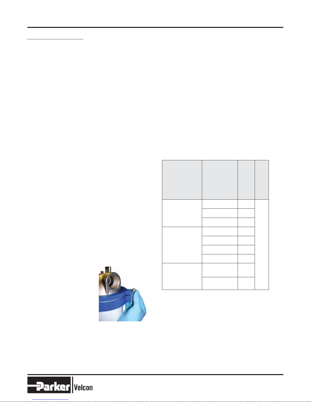
10. Lift shell up to the housing head, making sure
the head O-ring is in
place. Align shell bolts so
they do not interfere with
inlet and outlet piping.
Rotate bolts over clamp
top half (see photo).
Tighten all bolts to 33
ft-lbs, alternating in a
crisscross fashion.
Note: Small O-rings on bolts do not seal, but just
hold washers next to bolt head.
11. Close the drain valve and open isolation valves.
12. Open vent valve so the vessel slowly bleeds air
from the top vent while lling the housing.
13. Close the vent when the housing has lled.
Check all ttings and the head/shell junction
for leaks.
REPLACEMENT PARTS
e VF-61 is shipped with a Buna-N O-ring installed.
Some fuels, especially unleaded gasoline, may cause
excessive swelling of the O-ring. If this is a problem,
a Viton O-ring should be used. When ordering
replacement O-rings from Velcon, be sure
to specify:
G-0986 for Buna-N or G-0986A for Viton
Replacements are available from any commercial
supplier of O-rings. When placing an order, specify size
2-257 in the desired material.
CARTRIDGE SELECTION TABLE
TYPE
Pleated filter
media for dirt
removal
Aquacon
and water removal
Coalescer for dirt
and water removal
dirt
MODEL
NUMBER
FO-512PL1/2 0.5
FO-512PL05 5
FO-512PL25 25
AC-51205 5
AD-51225 25
ACO-51201P 0.5
ASL-51201 1
OS-51288 0.5
OS-51286 5
MICRON RATING
COLLAPSE
STRENGTH
75 psi
CAUTION: Do not use Aquacon cartridges with pre-
mixed jet fuel containing anti-icing additives.
WARNING: Aquacon
®
cartridges will not remove water
from fuel containing alcohol-blending
agents (commonly called gasohol).
For removal of solids, please use Velcon
particle removal filters specifically made for
gasohol. Consult your Parker
Velcon representative.
Parker Hanni n Corporation
2
Aerospace Filtration Division
1210 Garden of the Gods Road
Colorado Springs, CO 80907 USA
 Loading...