

Velatia Ormazabal cpg.1-c, Ormazabal cpg.1-v2, Ormazabal cpg.1-f1, Ormazabal cpg.1-f2, Ormazabal cpg.1-s1 General Instructions Manual
...
cpg.1
Fully SF6 gas insulated single and
double busbar GIS switchgears up
to 36 kV in accordance with IEC
Standards
General Instructions
IG-137-EN, version 03; 23/06/2016
LIB

Legal Deposit: BI-1548/2015
CAUTION!
When medium voltage equipment is operating, certain components are live, other parts may be in movement and some may reach high
temperatures. Therefore, the use of this equipment poses electrical, mechanical and thermal risks.
In order to ensure an acceptable level of protection for people and property, and in compliance with applicable environmental
recommendations, Ormazabal designs and manufactures its products according to the principle of integrated safety, based on the
following criteria:
• Elimination of hazards wherever possible.
• Where elimination of hazards is neither technically nor economically feasible, appropriate protection functions are
incorporated in the equipment.
• Communication about remaining risks to facilitate the design of operating procedures which prevent such risks, training
for the personnel in charge of the equipment, and the use of suitable personal protective equipment.
• Use of recyclable materials and establishment of procedures for the disposal of equipment and components so that
once the end of their service lives is reached, they are duly processed in accordance, as far as possible, with the
environmental restrictions established by the competent authorities.
Consequently, the equipment to which the present manual refers complies with the requirements of section 11.2 of Standard IEC
62271-1. It must therefore only be operated by appropriately qualified and supervised personnel, in accordance with the requirements
of standard EN 50110-1 on the safety of electrical installations and standard EN 50110-2 on activities in or near electrical installations.
Personnel must be fully familiar with the instructions and warnings contained in this manual and in other recommendations of a more
general nature which are applicable to the situation according to current legislation
1
.
The above must be carefully observed, as the correct and safe operation of this equipment depends not only on its design but also on
general circumstances which are in general beyond the control and responsibility of the manufacturer. More specifically:
• The equipment must be handled and transported appropriately from the factory to the place of installation.
• All intermediate storage should occur in conditions which do not alter or damage the characteristics of the equipment or
its essential components.
• Service conditions must be compatible with the equipment rating.
• The equipment must be operated strictly in accordance with the instructions given in the manual, and the applicable
operating and safety principles must be clearly understood.
• Maintenance should be performed properly, taking into account the actual service and environmental conditions in the
place of installation.
The manufacturer declines all liability for any significant indirect damages resulting from violation of the guarantee, under any jurisdiction,
including loss of income, stoppages and costs resulting from repair or replacement of parts.
Warranty
The manufacturer guarantees this product against any defect in materials and operation during the contractual period. In the event that
defects are detected, the manufacturer may opt either to repair or replace the equipment. Improper handling of this equipment and its
repair by the user shall constitute a violation of the warranty.
Registered Trademarks and Copyrights
All registered trademarks cited in this document are the property of their respective owners. The intellectual property of this manual
belongs to Ormazabal.
1
For example, in Spain the “Regulation on technical conditions and guarantees for safety in high voltage electrical installations” –
Royal Decree 337/2014 is obligatory.
In view of the constant evolution in standards and design, the characteristics of the elements contained in this manual are subject to
change without prior notice. These characteristics, as well as the availability of components, are subject to confirmation by Ormazabal.

General instructions
cpg.1
Fully SF6 gas insulated single and double busbar GIS switchgears up to 36 kV in accordance
with IEC Standards
Contents
1 Description and main characteristics .......................................... 6
1.1 Models .................................................................................6
1.2 Standards applied........................................................................6
1.3 Main components ........................................................................7
1.3.1 Levers for manual operation .........................................................10
1.3.2 Main manual operation panel ........................................................11
1.4 Name plate.............................................................................14
2 Technical characteristics ................................................... 15
3
2.1 Electrical characteristics .................................................................15
2.2 Mechanical characteristics ...............................................................16
2.2.1 Dimensions and weights...........................................................16
2.2.2 Protection grade .................................................................17
3 Service conditions......................................................... 18
4 Handling and transport ..................................................... 19
4.1 Transport conditions ....................................................................19
4.2 Lifting means...........................................................................19
5 Storage conditions ........................................................ 21
6 Installation ............................................................... 22
6.1 Unpacking the equipment ................................................................22
6.2 List of supplied materials.................................................................22
6.3 Minimum installation distances............................................................30
6.4 Cable trench ...........................................................................30
6.5 Fastening to the floor ....................................................................31
6.6 Cubicle joints ..........................................................................32
6.6.1 cpg.1-v ..........................................................................32
6.6.2 cpg.1-s ..........................................................................33
6.6.3 cpg.1-ct / cpg.1-cl ..................................................................33
6.6.4 cpg.1-f ..........................................................................34
IG-137-EN version 03; 23/06/2016

4
General Instructions
cpg.1
Fully SF6 gas insulated single and double busbar GIS switchgears up to 36 kV in accordance
with IEC Standards
6.7 Equipment earthing .....................................................................34
6.7.1 Top section.......................................................................34
6.7.2 Bottom section ....................................................................35
6.7.3 Top and bottom earth side link........................................................35
7 Operations sequence ...................................................... 36
7.1 cpg.1-v1 cubicle . . . . . . . . . . . . . . . . . . . . . . . . . . . . . . . . . . . . . . . . . . . . . . . . . . . . . . . . . . . . . . . . . . . . . . . . . 36
7.1.1 Commissioning from open position ....................................................37
7.1.1 Medium voltage cable earthing .......................................................38
7.2 cpg.1-v2 cubicle .........................................................................39
7.2.1 Commissioning from open position ....................................................39
7.2.2 Medium voltage cable earthing .......................................................40
7.2.3 Replacing a busbar ................................................................40
7.3 cpg.1-s1 cubicle .........................................................................42
7.3.1 Connection.......................................................................42
7.3.2 Earthing .........................................................................43
7.4 cpg.1-s2 cubicle .........................................................................43
7.4.1 Connection.......................................................................44
7.4.2 Earthing .........................................................................44
7.5 cpg.1-c cubicle ..........................................................................45
7.5.1 Busbar coupling ...................................................................46
7.5.2 Busbar earthing on the right .........................................................47
7.5.3 Busbar earthing on the left...........................................................48
7.6 cpg.1-cl cubicle..........................................................................49
7.6.1 Busbar coupling ...................................................................49
7.6.2 Busbar earthing on the right .........................................................50
7.6.3 Busbar earthing on the left: ..........................................................52
7.7 cpg.1-ct cubicle .........................................................................53
7.7.1 Busbar connection .................................................................54
7.7.2 Main busbar earthing ...............................................................55
7.7.3 Secondary busbar earthing ..........................................................56
7.8 cpg.1-f1 cubicle .........................................................................57
7.8.1 Commissioning the cubicle ..........................................................57
7.8.2 Earthing .........................................................................58
7.9 cpg.1-f2 cubicle .........................................................................58
7.9.1 Commissioning the cubicle ..........................................................59
7.9.2 Earthing .........................................................................59
7.10 Fuse replacement sequence in cpg.1-f .....................................................60
7.10.1 Selection of fuses recommended for cpg.1-f ............................................62
IG-137-EN version 03; 23/06/2016

General instructions
cpg.1
Fully SF6 gas insulated single and double busbar GIS switchgears up to 36 kV in accordance
with IEC Standards
8 Safety elements ........................................................... 63
8.1 Maintenance ...........................................................................63
8.2 Voltage presence detectors ...............................................................63
8.2.1 Locking with a padlock..............................................................64
8.2.1 Locking with lock ..................................................................64
8.3 Interlocks ..............................................................................64
9 Spares and accessories .................................................... 65
9.1 Preventive maintenance for the cpg.1 cubicle ................................................65
10 Environmental information ................................................ 66
10.1 Sulphur Hexafluoride SF6................................................................66
10.2 Recyclability ..........................................................................66
5
IG-137-EN version 03; 23/06/2016
Description and main characteristics
6
Fully SF6 gas insulated single and double busbar GIS switchgears up to 36 kV in accordance
1 Description and main characteristics
General Instructions
cpg.1
with IEC Standards
The cpg.1 family is a series of GIS modular cubicles
with full SF6 gas insulation, for single and double busbar
primary distribution applications in medium voltage
networks up to 36 kV.
1.1 Models
Function Designation
Single busbar Double busbar
Circuit breaker cubicle
Disconnector cubicle
Transversal busbar coupling cubicle
Longitudinal busbar coupling cubicle
Fuse protection cubicle
cpg.1-v1 cpg.1-v2
cpg.1-s1 cpg.1-s2
-- cpg.1-ct
cpg.1-c cpg.1-cl
cpg.1-f1 cpg.1-f2
1.2 Standards applied
Standard Description
IEC 62271-1
IEC 62271-200
IEC 62271-100
IEC 62271-102
IEC 62271-105
IEC 62271-206 / IEC 61243-5
Common specications for high voltage switchgear standards
Metal-enclosed alternating current switchgear for rated voltages
above 1 kV and below or equal to 52 kV
Alternating current circuit breakers
Alternating current disconnectors and earthing switches
Alternating current circuit breaker-fuse combinations for rated voltages
above 1 kV and below or equal to 52 kV
Voltage presence indicating systems
IG-137-EN version 03; 23/06/2016
General instructions
Description and main characteristics
cpg.1
Fully SF6 gas insulated single and double busbar GIS switchgears up to 36 kV in accordance
with IEC Standards
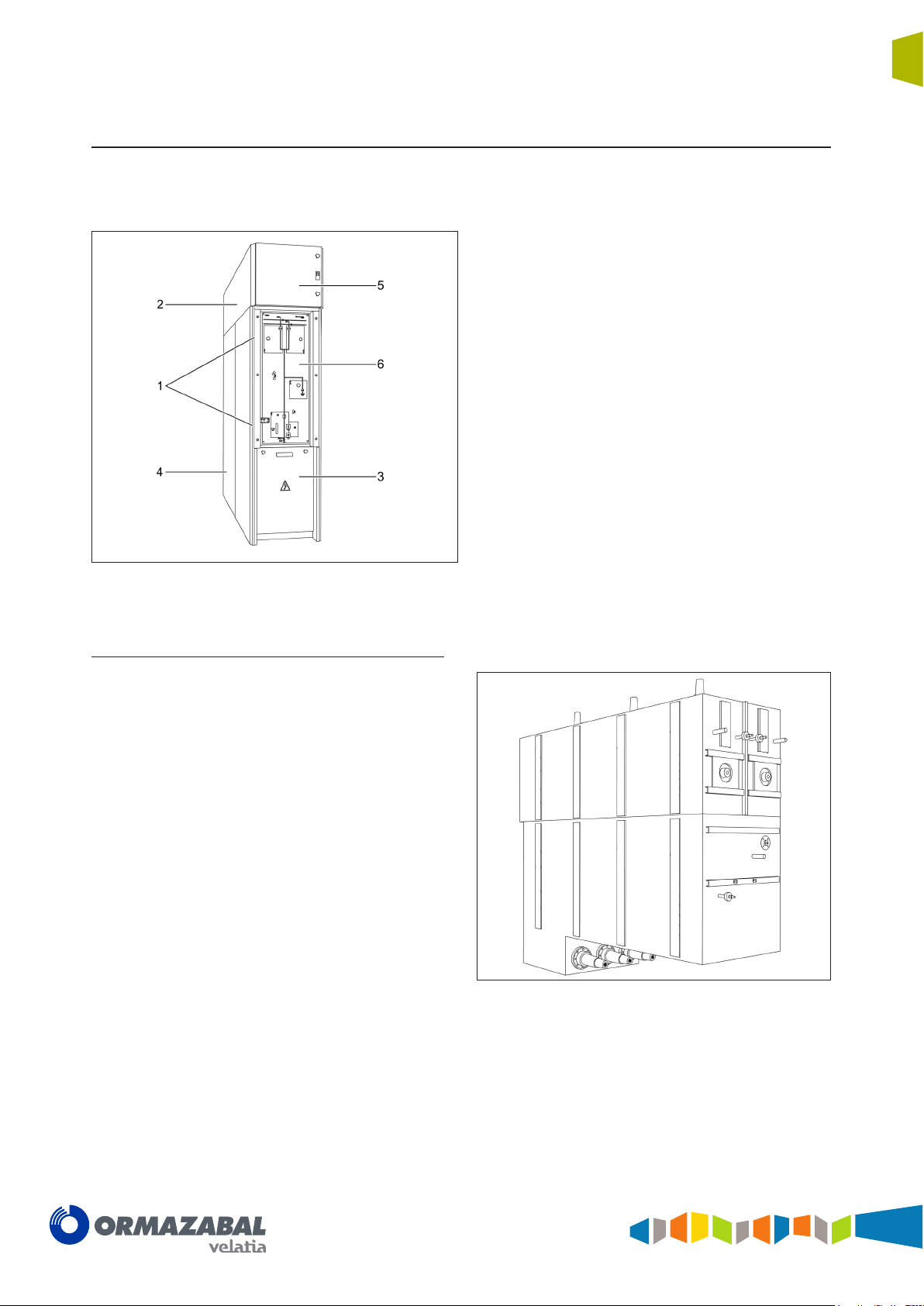
1.3 Main components
Each cubicle is made up of a series of independent
compartments:
1. Gas tanks
2. Busbar compartment
3. Cable compartment
4. Gas pressure relief duct (optional)
5. Control compartment
6. Driving mechanism area
7
Figure 1.1 Main elements of cpg.1 cubicles
Gas tanks
These are the compartments which house the switching
and breaking switchgear, where the insulating medium is
gas. There are 2 or 3 separate compartments:
SF
6
• 1 for each of the feeder disconnectors
• 1 for the circuit breaker and the earthing switch
These are sealed compartments, made of stainless steel
and sealed for life. They are designed and tested to
withstand an internal arc of up to 31.5 kA - 1 s.
Depending on the function for which the cubicle was
designed, it may contain the following components:
• Feeder disconnectors
• Earthing switch
• Internal busbar and connections
• Vacuum circuit breaker
• Switch - disconnector
• Fuse holders
Figure 1.2 Gas tanks of circuit breaker and disconnectors for
cpg.1-v2 cubicle
There are sets of bushings in the top and bottom of the
compartments for connection of the busbar and the power
cables respectively.
IG-137-EN version 03; 23/06/2016
Description and main characteristics
8
Fully SF6 gas insulated single and double busbar GIS switchgears up to 36 kV in accordance
For testing the gas pressure in each compartment, a
temperature-compensated pressure switch is installed,
Top busbar
General Instructions
cpg.1
with IEC Standards
with a volt-free contact, for possible use as a remote alarm
or blocking/trip for the functional unit.
This is used for connecting cubicles. It has solid and
shielded insulation, earthed by means of the compartment's
specific earthing bar.
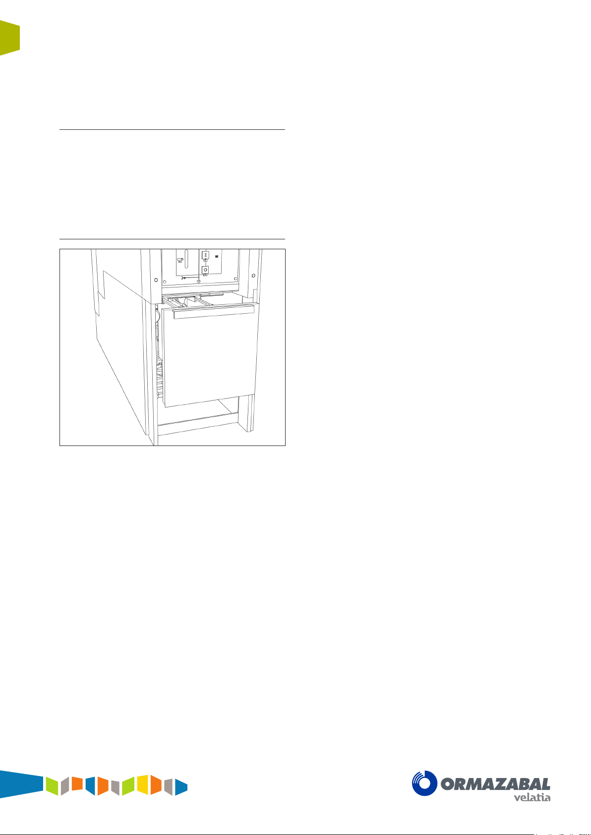
Cable compartment
As an option, the busbar is able to segregate the phases
by means of a set of earthed metal plates (metal-clad).
Toroidal current transformers and/or plug-in voltage
transformers can be installed in this compartment, thus
avoiding the need for metering cubicles.
In the most complete case, the base can house the
following components:
• Phase segregation consisting of the main box
and the segregating cover.
• Up to 4 screw-in shielded terminals per phase,
as well as space for the corresponding incoming
power cables.
• Clamp flanges for the medium voltage cables.
• Earthing plates.
• Toroidal current transformers.
• Plug-in voltage transformers.
• Surge arresters.
Figure 1.3 Phase segregation in the cable compartment
(optional)
Located in the bottom part of the cubicle, this has a cover,
interlocked with the earthing circuit, which allows front
access to the medium voltage cables.
All the elements making up the enclosure are earthed by
means of a conductor consisting of a copper bar capable
of withstanding the rated short-time current. It is located
in the base in such a way that it does not need to be
dismantled in order to insert or remove a cable and its
corresponding termination.
IG-137-EN version 03; 23/06/2016
General instructions
Description and main characteristics
cpg.1
Fully SF6 gas insulated single and double busbar GIS switchgears up to 36 kV in accordance
with IEC Standards
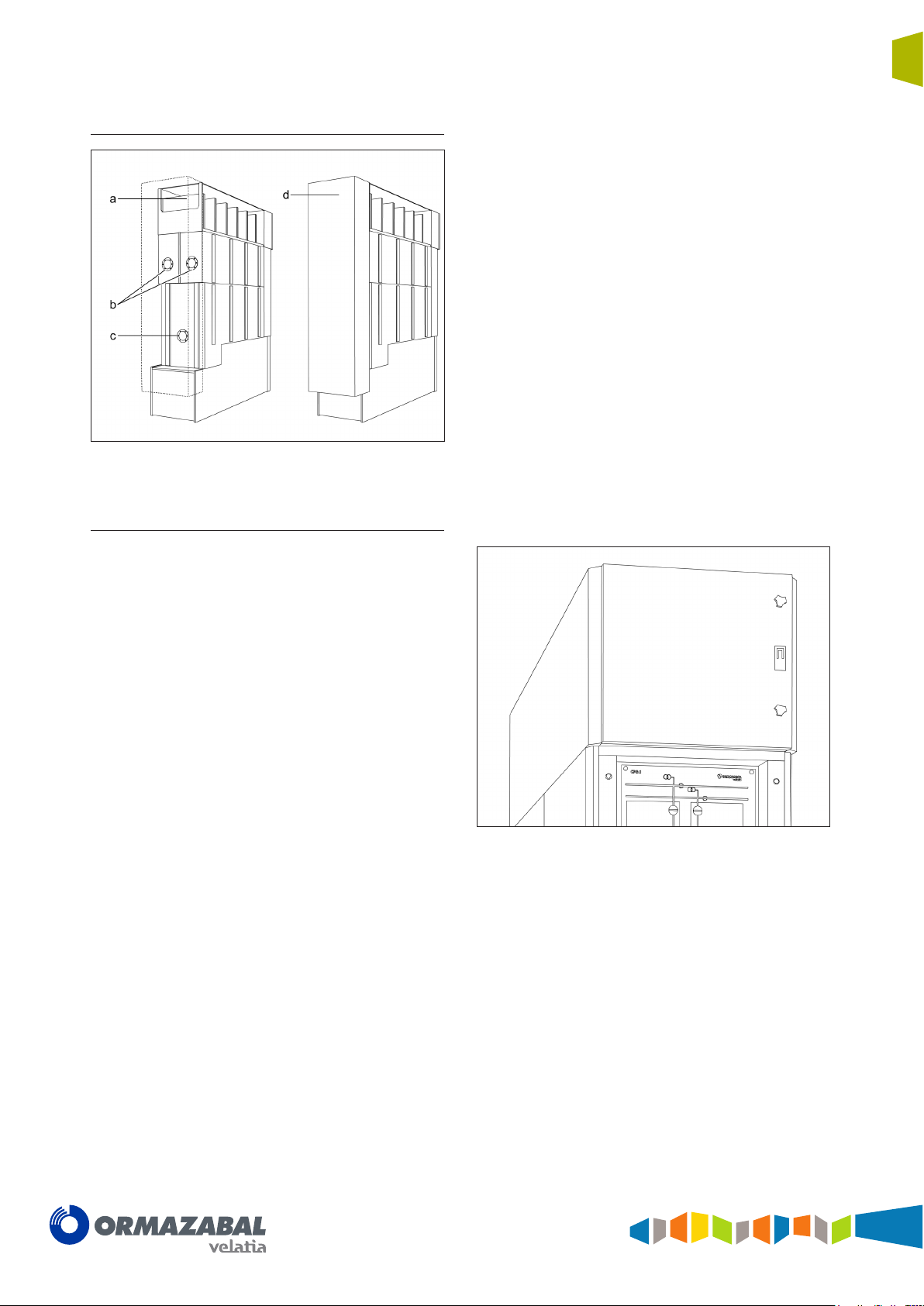
Gas pressure relief duct (optional)
This component is used to direct the gases produced by
an internal arc in any of the compartments towards the
top of the cubicle: Disconnector compartment and circuit
breaker compartment, top busbar compartment and cable
compartment.
a. Gas vent from busbar compartment
b. Gas vent from disconnector compartments
c. Gas vent from circuit breaker and earthing switch
compartment
d. Internal arc gas directional duct (optional)
Figure 1.4 Internal arc gas pressure relief duct (optional)
9
Control compartment
Placed at the top of the cubicle and separate from the
medium voltage area, this is ready for installation of the
metering equipment and protection relays. It contains
the whole terminal block with the control signals already
identified.
Figure 1.5 Control compartment
IG-137-EN version 03; 23/06/2016
10
Description and main characteristics
Fully SF6 gas insulated single and double busbar GIS switchgears up to 36 kV in accordance
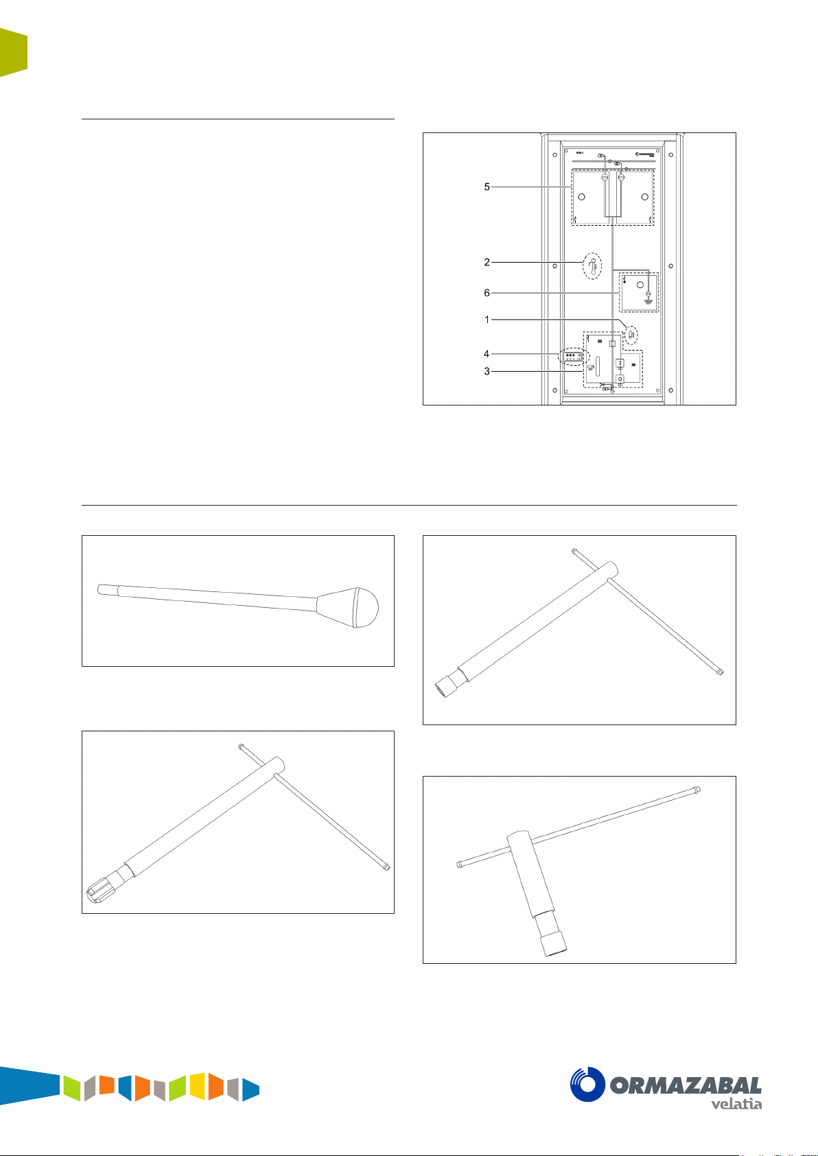
Driving mechanism area
In addition to a mimic diagram customised for each type of
cubicle, this has the driving elements in its middle section:
disconnector/earthing switch and circuit breaker driving
mechanisms, circuit breaker opening/closing pushbuttons,
status indicators, groove for access of the spring loading
lever, etc.
1. Cable compartment cover interlocking
2. Driving shaft access interlocking
3. Circuit breaker operation and indication area
4. Voltage presence - absence detector
5. Feeder disconnector operation and indication area
6. Earthing switch operation and indication area
General Instructions
cpg.1
with IEC Standards
Figure 1.6 General manual operation panel detail
1.3.1 Levers for manual operation
Figure 1.7 Lever for manual loading of the circuit breaker
springs in cpg.1-v cubicle
Figure 1.9 Manual driving lever of the earthing switch
Figure 1.8 Manual operation lever of the feeder disconnectors
IG-137-EN version 03; 23/06/2016
Figure 1.10 Manual operation lever of the cpg.1-f cubicle
General instructions
Description and main characteristics
cpg.1
Fully SF6 gas insulated single and double busbar GIS switchgears up to 36 kV in accordance
with IEC Standards
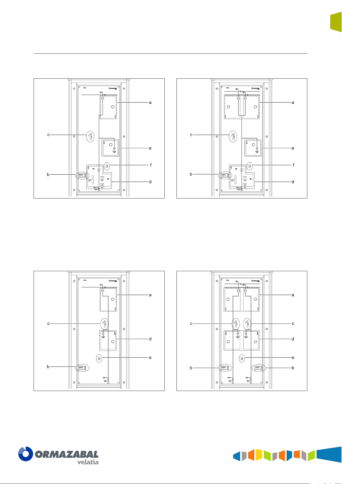
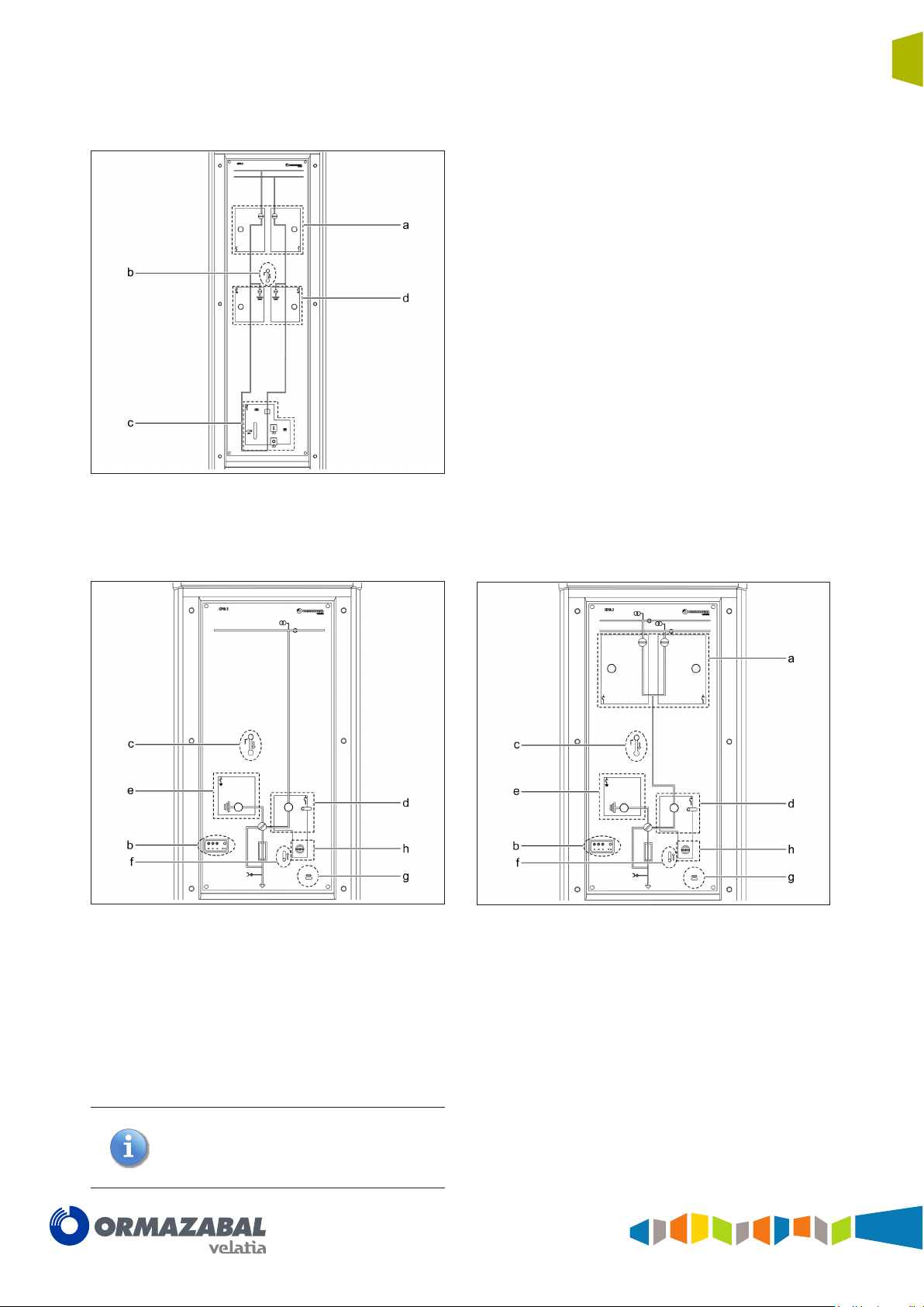
1.3.2 Main manual operation panel
11
cpg.1-v1
Figure 1.11 Manual operation general panel and mimic
diagram for cpg.1-v1
a. Disconnector operation and indication area
b. Voltage presence-absence indicator
c. Driving shaft access handle
d. Circuit breaker operation and indication area
e. Earthing switch operation and indication area
f. Cable compartment cover interlocking
cpg.1-v2
Figure 1.12 Manual operation general panel and diagram for
cpg.1-v2
cpg.1-s1
Figure 1.13 Manual operation general panel and mimic
diagram for cpg.1-s1
a. Disconnector operation and indication area
b. Voltage presence-absence indicator
c. Driving shaft access handle
d. Earthing switch operation and indication area
e. Cable compartment cover interlocking
cpg.1-s2
Figure 1.14 Manual operation general panel and mimic
diagram for cpg.1-s2
IG-137-EN version 03; 23/06/2016
12
Description and main characteristics
Fully SF6 gas insulated single and double busbar GIS switchgears up to 36 kV in accordance
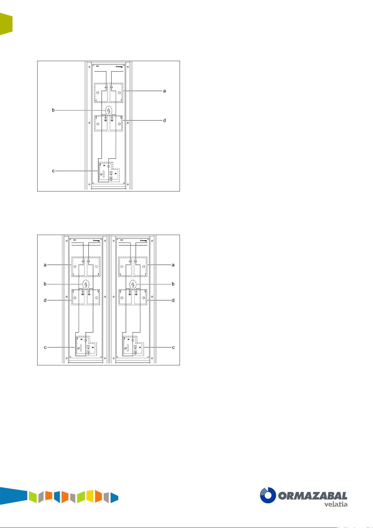
cpg.1-c
General Instructions
cpg.1
with IEC Standards
a. Disconnector operation and indication area
b. Driving shaft access handle
c. Circuit breaker operation and indication area
d. Earthing switch operation and indication area
Figure 1.15 Manual operation general panel and mimic
diagram for cpg.1-c
cpg.1-cl
Figure 1.16 Manual operation general panel and mimic
diagram for cpg.1-cl
a. Disconnector operation and indication area
b. Driving shaft access handle
c. Circuit breaker operation and indication area
d. Earthing switch operation and indication area
IG-137-EN version 03; 23/06/2016
General instructions
Description and main characteristics
cpg.1
Fully SF6 gas insulated single and double busbar GIS switchgears up to 36 kV in accordance
with IEC Standards
cpg.1-ct
a. Disconnector operation and indication area
b. Driving shaft access handle
c. Circuit breaker operation and indication area
d. Earthing switch operation and indication area
13
Figure 1.17 Manual operation general panel and mimic
diagram for cpg.1-ct
cpg.1-f1
Figure 1.18 Manual operation general panel and mimic
diagram for cpg.1-f1
cpg.1-f2
Figure 1.19 Manual operation general panel and mimic
diagram for cpg.1-f2
a. Disconnector operation and indication area
b. Voltage presence-absence indicator
c. Driving shaft access handle
d. Switch - disconnector operation and indication area
e. Earthing switch operation and indication area
f. Cable compartment cover interlocking
g. Blown fuse indicator
h. Switch manual opening handle
Conguration with motorised circuit breaker-
disconnector driving mechanism.
Operation of the earthing switch mechanism
cannot be motorised.
IG-137-EN version 03; 23/06/2016
14
Description and main characteristics
Fully SF6 gas insulated single and double busbar GIS switchgears up to 36 kV in accordance
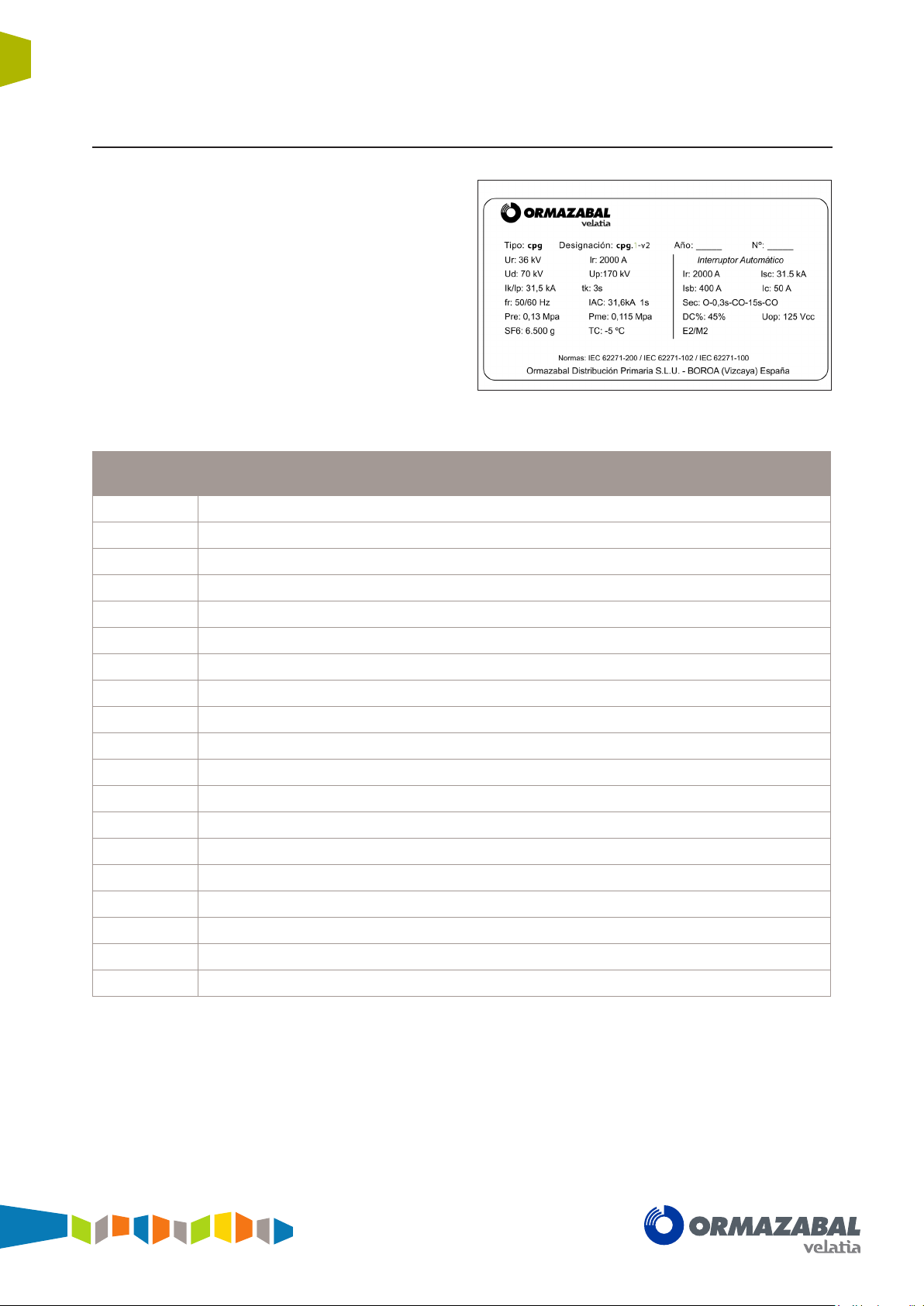
1.4 Name plate
Every cubicle incorporates a name plate, indicating some
of the following values:
Name plate
General Instructions
cpg.1
with IEC Standards
Figure 1.20 Example of name plate for cpg.1-v2 cubicle
Nº Cubicle serial number
(*)
.
Type Ormazabal cubicle system.
Designation Cubicle model.
Standard Regulations applied to the equipment.
U
U
U
f
r
I
r
I
k
t
k
l
sc
P
P
SF
/ I
r
p
d
p
re
me
6
Equipment rated voltage.
Lightning impulse withstand voltage.
Power frequency withstand voltage.
Equipment rated frequency.
Equipment rated current.
Short-time withstand current/Short-time withstand peak value.
Short-circuit time.
Rated short-circuit breaking capacity.
Gas pressure inside the compartment (MPa).
Minimum operation pressure (MPa).
Weight (g) of insulating fluid.
Year Year of manufacture.
TC Minimum working temperature.
DC% Percentage value of the aperiodic component.
U
op
(*)
In the case of any incidents, note down this number and report it to Ormazabal.
Driving mechanism rated supply voltage for one closing and one opening operation.
IG-137-EN version 03; 23/06/2016
General instructions
Technical characteristics
cpg.1
Fully SF6 gas insulated single and double busbar GIS switchgears up to 36 kV in accordance
with IEC Standards
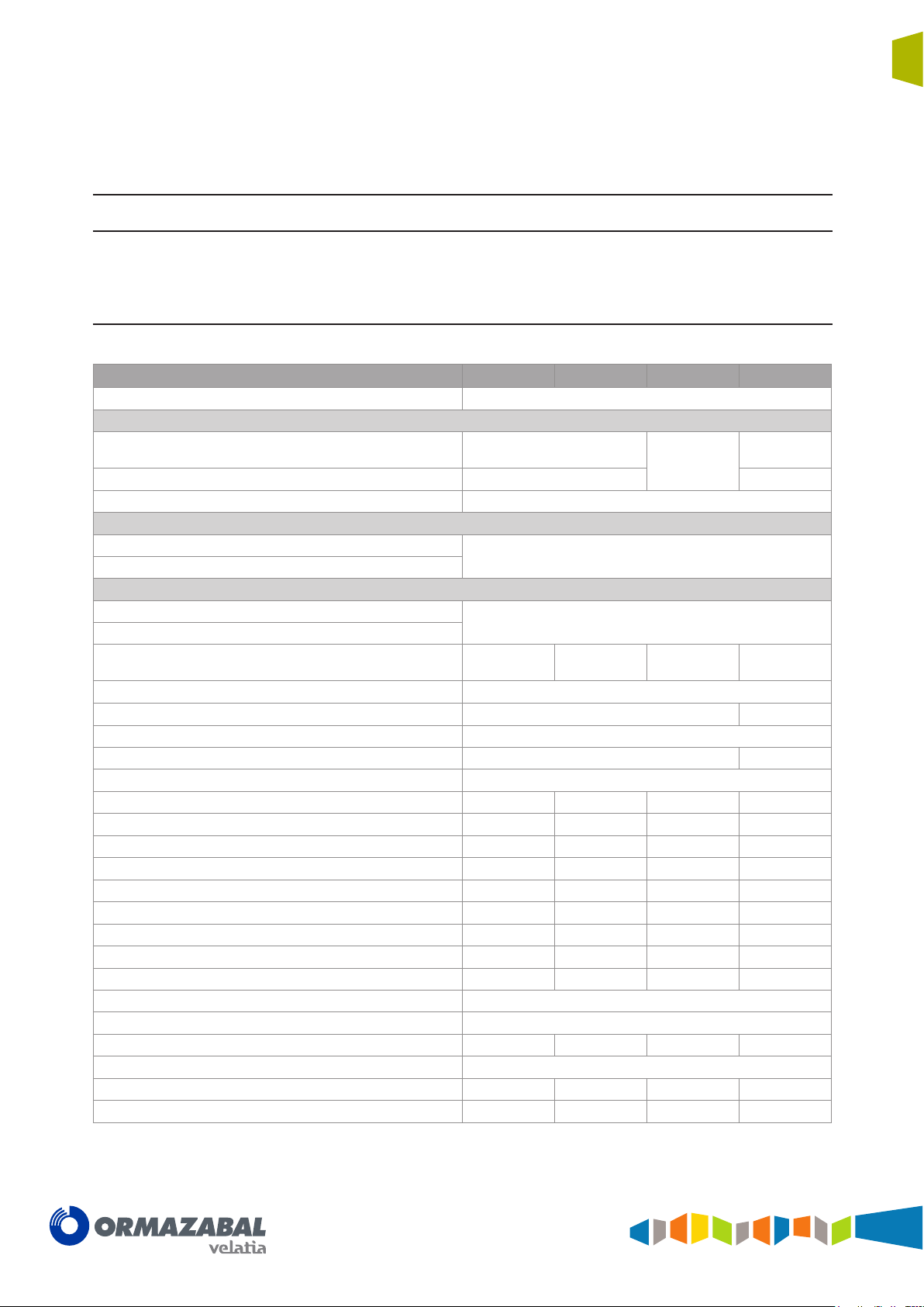
2 Technical characteristics
2.1 Electrical characteristics
15
Characteristics
Rated voltage kV 24 / 36
Rated current in continuous operation
In main busbar A 1250 / 1600 / 2000
Branching A 630 / 1250 / 1600 / 2000 200
Rated frequency Hz 50 / 60
Lightning impulse voltage
Between phases and phase-to-earth kV
Isolating distance kV
Power frequency voltage
Between phases and phase-to-earth kV
Isolating distance kV
Reclosing sequence
Rated short-time current main circuit kA 25 / 31.5
Rated short-time current earth circuit kA 25 / 31.5 1 / 3
Rated peak current main circuit kA 62.5 / 80
Rated peak current earth circuit kA 62.5 / 80 2.5 / 7.5
Rated short-circuit time s 1 / 3
Short-circuit breaking rated current kA 25 / 31.5 25 / 31.5
Breaking rated current in short-circuit kA 62.5 / 80 62.5 / 80
DC % 45 45
Opening time ms < 45 < 45
Short-circuit breaking time ms < 50 < 50
No-load feeder rated current A 50 50
No-load cable rated current A 31.5 / 50 31.5 / 50
Condenser battery rated current A 400 400
Transfer rated current A 800
Internal fault rated current kA 31.5
Internal fault rated time s 1
Electrical endurance E2/C2 E2/C2 E3 / C2
Auxiliary voltage
Motorised charging time ms < 15 < 15
Mechanical endurance M2 M0 M2 M2
V
cpg.1-v1/v2 cpg.1-s1/s2 cpg.1-c/cl/ct cpg.1-f
1250 / 1600
/ 2000
125 / 170
145 / 195
50 / 70
60 / 80
dc
O-0.3 s-CO-
15 s-CO
NO
O-0.3 s-CO-
15 s-CO
125
1250 / 1600
/ 2000
NO
IG-137-EN version 03; 23/06/2016
16
Technical characteristics
Fully SF6 gas insulated single and double busbar GIS switchgears up to 36 kV in accordance
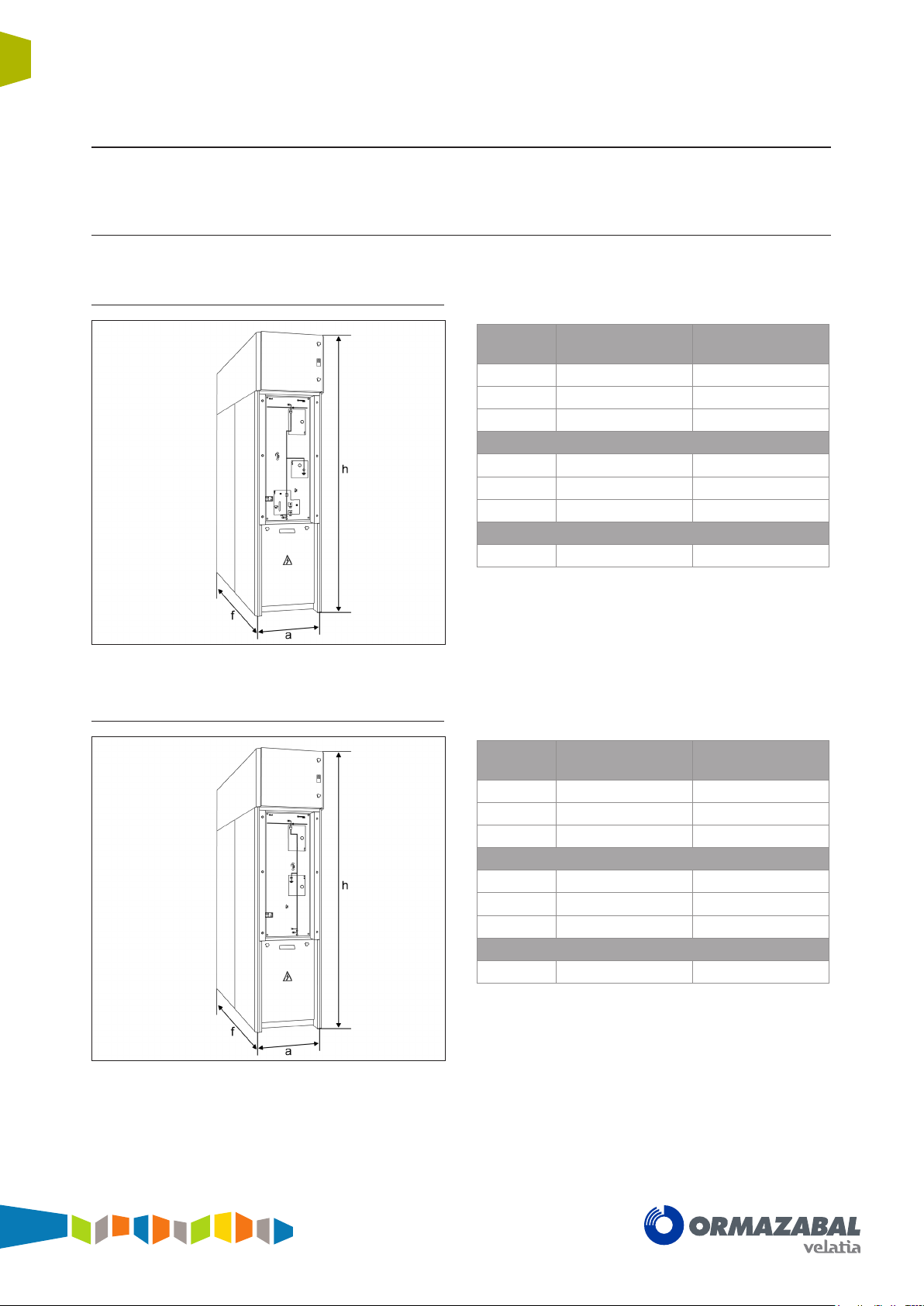
2.2 Mechanical characteristics
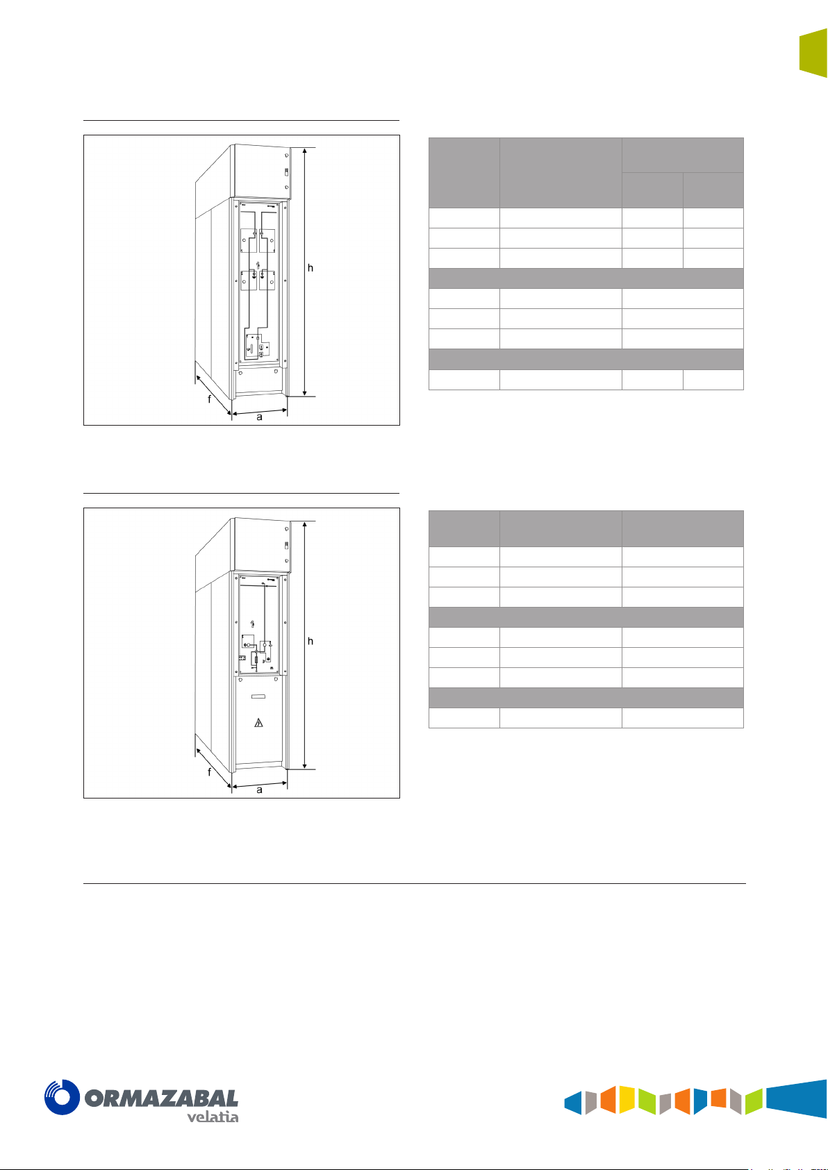
2.2.1 Dimensions and weights
cpg.1-v circuit breaker cubicle
General Instructions
cpg.1
with IEC Standards
Figure 2.1 Dimensions of cpg.1-v cubicle
cpg.1-s disconnector cubicle
Level
a
h
f
Anchors
b
c
d
With single busbar
cpg.1-v1
600 600
2500* 2500*
1900* 1900*
[1]
550 550
500 500
590 590
With double busbar
cpg.1-v2
Weight [kg]
Total
* For control compartment 480 mm high and 561 mm deep. For other
control compartment measurements, check with Ormazabal.
** Cubicles with IAC classification AFLR have an additional 30 kg weight.
[1]
See plan of anchoring points in section 6.5.
Level
a
h
f
Anchors
[2]
b
c
d
1100** 1400**
With single busbar
cpg.1-s1
600 600
2500* 2500*
1900* 1900*
550 550
500 500
590 590
With double busbar
cpg.1-s2
Weight [kg]
Total
1000** 1200**
Figure 2.2 Dimensions of cpg.1-s cubicle
* For control compartment 480 mm high and 561 mm deep. For other
control compartment measurements, check with Ormazabal.
** Cubicles with IAC classification AFLR have an additional 30 kg weight.
[2]
See plan of anchoring points in section 6.5.
IG-137-EN version 03; 23/06/2016
General instructions
Technical characteristics
cpg.1
Fully SF6 gas insulated single and double busbar GIS switchgears up to 36 kV in accordance
with IEC Standards
cpg.1-c busbar coupling cubicle
17
Figure 2.3 Dimensions of cpg.1-c cubicle
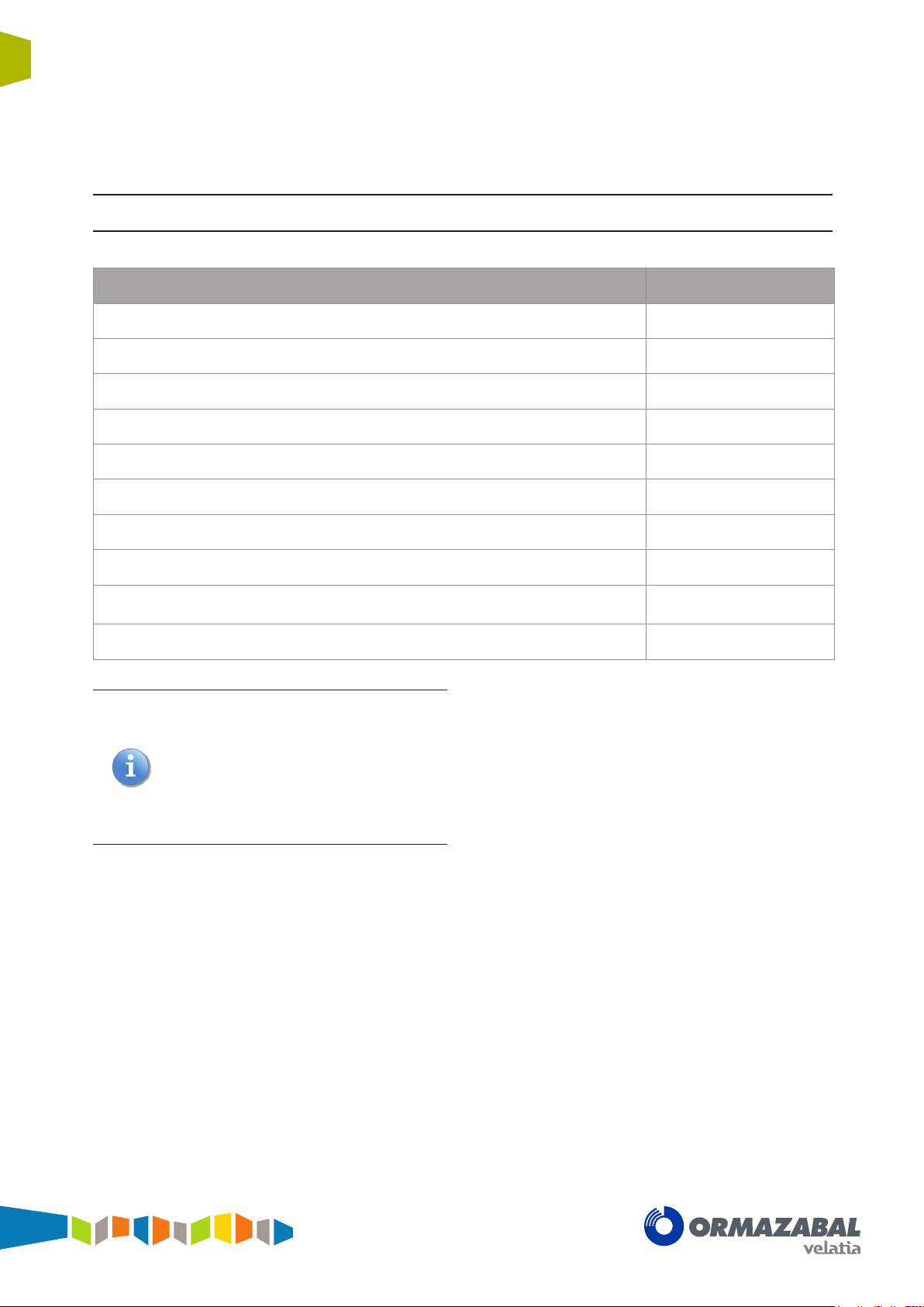
cpg.1-f fuse protection cubicle
With double busbar
cpg.1-cl cpg.1-ct
Level
a
h
f
Anchors
b
c
d
With single busbar
cpg.1-c
600 1200 600
2500* 2500* 2500*
1900* 1900* 1900*
[3]
550 550
500 500
590 590
Weight [kg]
Total
* For control compartment 480 mm high and 561 mm deep. For other
control compartment measurements, check with Ormazabal.
** Cubicles with IAC classification AFLR have an additional 30 kg weight.
[3]
See plan of anchoring points in section 6.5.
Level
With single busbar
a
h
f
Anchors
[4]
b
c
d
1500* 3000* 1500*
With double busbar
cpg.1-f1
600 600
2500* 2500*
1900* 1900*
550 550
500 500
590 590
cpg.1-f2
Weight [kg]
Total
1000** 1300**
Figure 2.4 Dimensions of cpg.1-f cubicle
2.2.2 Protection grade
All power circuit elements are installed inside a stainless
steel gas tank, providing IP65 degree of protection.
IG-137-EN version 03; 23/06/2016
* For control compartment 480 mm high and 561 mm deep. For other
control compartment measurements, check with Ormazabal.
** Cubicles with IAC classification AFLR have an additional 30 kg weight.
[4]
See plan of anchoring points in section 6.5.
The maximum degree of protection for the cubicle
assembly, in all designations, is IP42.
18
Service conditions
Fully SF6 gas insulated single and double busbar GIS switchgears up to 36 kV in accordance
3 Service conditions
Installation Indoor
Maximum ambient temperature + 40 ºC
Minimum ambient temperature – 5 ºC
Maximum mean ambient temperature, measured over a 24-hour period + 35 ºC
Maximum mean relative humidity, measured over a 24-hour period < 95%
General Instructions
cpg.1
with IEC Standards
Maximum mean relative humidity, measured over a 1-month period < 90%
Maximum height above sea level 1000 m
Solar radiation Negligible
Ambient air pollution (dust, smoke, corrosive and/or flammable gases, vapours or
salt)
Vibrations caused by causes external to the switchgear or by seismic movements Negligible
The specications refer to the section "Normal
service conditions for indoor cubicles" in the
IEC 62271-1 standard 'Common specications
for high voltage cubicle standards”.
For special service conditions: ambient
temperature above + 40 ºC, installation and/
or transport over 1000 m above sea level,
signicant pollution level, or others dierent to
those described, check with Ormazabal.
Insignificant
IG-137-EN version 03; 23/06/2016
General instructions
Handling and transport
cpg.1
Fully SF6 gas insulated single and double busbar GIS switchgears up to 36 kV in accordance
with IEC Standards
4 Handling and transport
4.1 Transport conditions
19
During transport, the switchgear must be perfectly seated
and fixed so that it cannot move about and possibly
damage the equipment. Always in upright position, directly
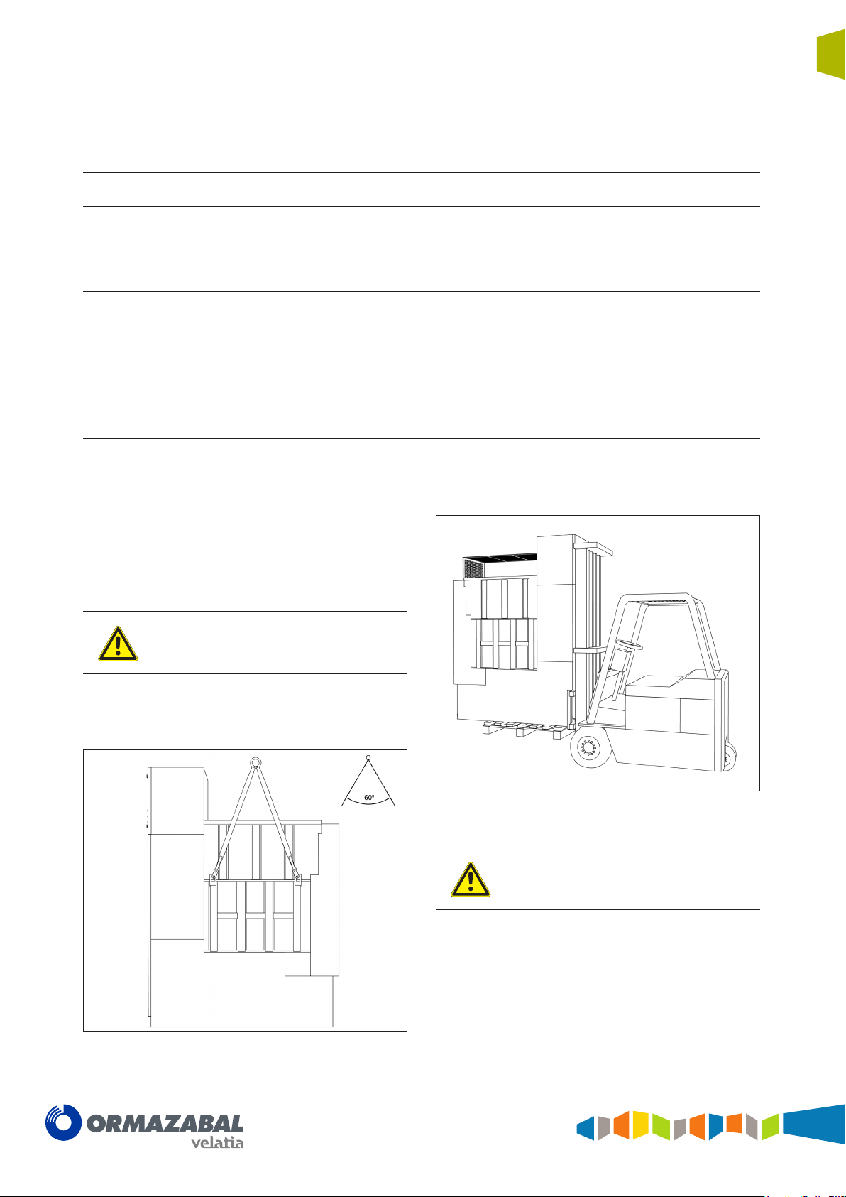
4.2 Lifting means
The cubicles must always be kept upright, directly on the
ground or on a pallet depending on the type of handling
involved.
The cpg.1 cubicles are fitted with four eyebolt-type
suspension points which can be used for handling the
cubicles with a crane; to do this, four slings or cloth straps
are used capable of carrying at least 2500 kg.
Check that the cubicle is perfectly balanced at
all times.
Once the cubicle has been sited as close as possible to
its final installation position, remove all four suspension
points from the cubicle.
on the ground or on a pallet, depending on the type of
handling involved. Check that the switchgear is perfectly
balanced at all times.
If a forklift truck is available, this should have a fork at least
2 m long and be capable of carrying at least 2500 kg.
Figure 4.1 Lifting a cpg.1 cubicle using slings
IG-137-EN version 03; 23/06/2016
Figure 4.2 Lifting a cpg.1 cubicle by forklift truck
The cubicle should always be loaded onto the
forklift truck from the front, as indicated in
gure 4.2.
20
Handling and transport
Fully SF6 gas insulated single and double busbar GIS switchgears up to 36 kV in accordance
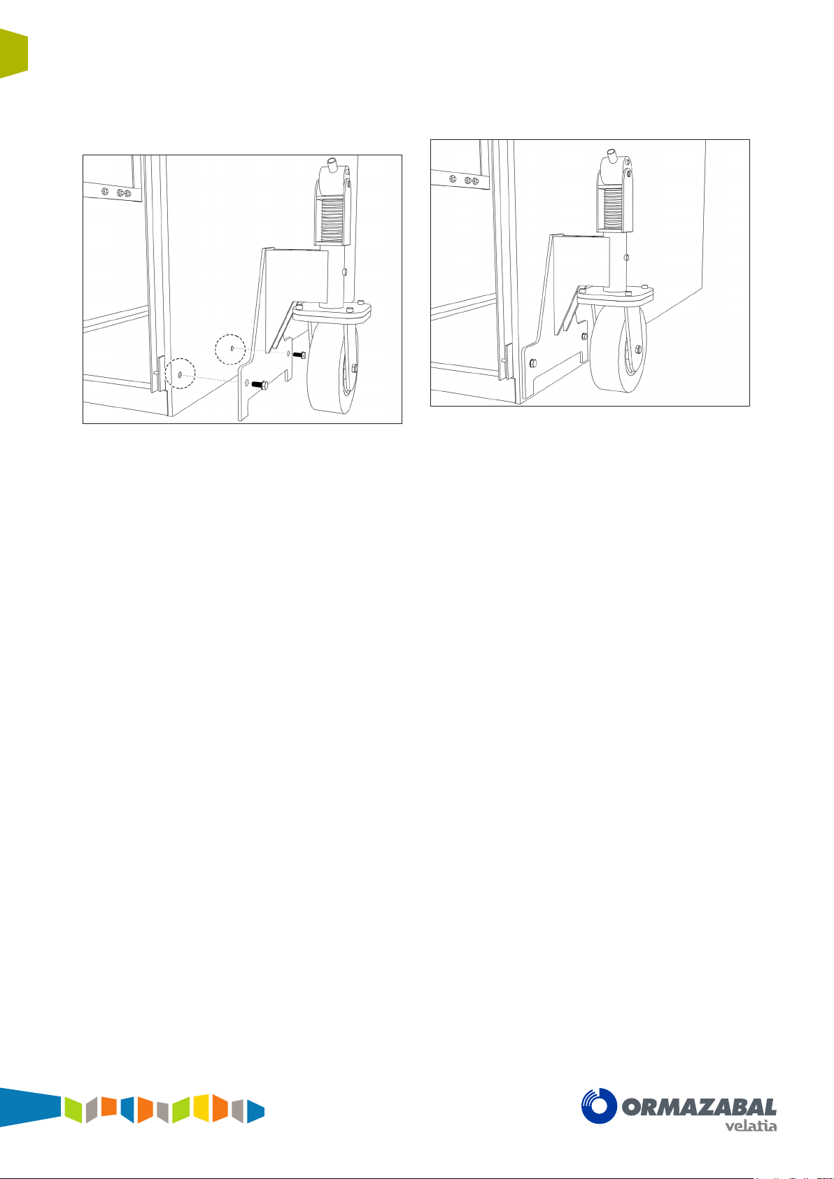
To put the cubicles in their final position, elevating caster
wheels can be used; please check with Ormazabal.
Figure 4.3 Wheel anchors in the cubicle
General Instructions
cpg.1
with IEC Standards
Figure 4.4 Detail of the positioned wheel
IG-137-EN version 03; 23/06/2016
General instructions
cpg.1
Fully SF6 gas insulated single and double busbar GIS switchgears up to 36 kV in accordance
with IEC Standards
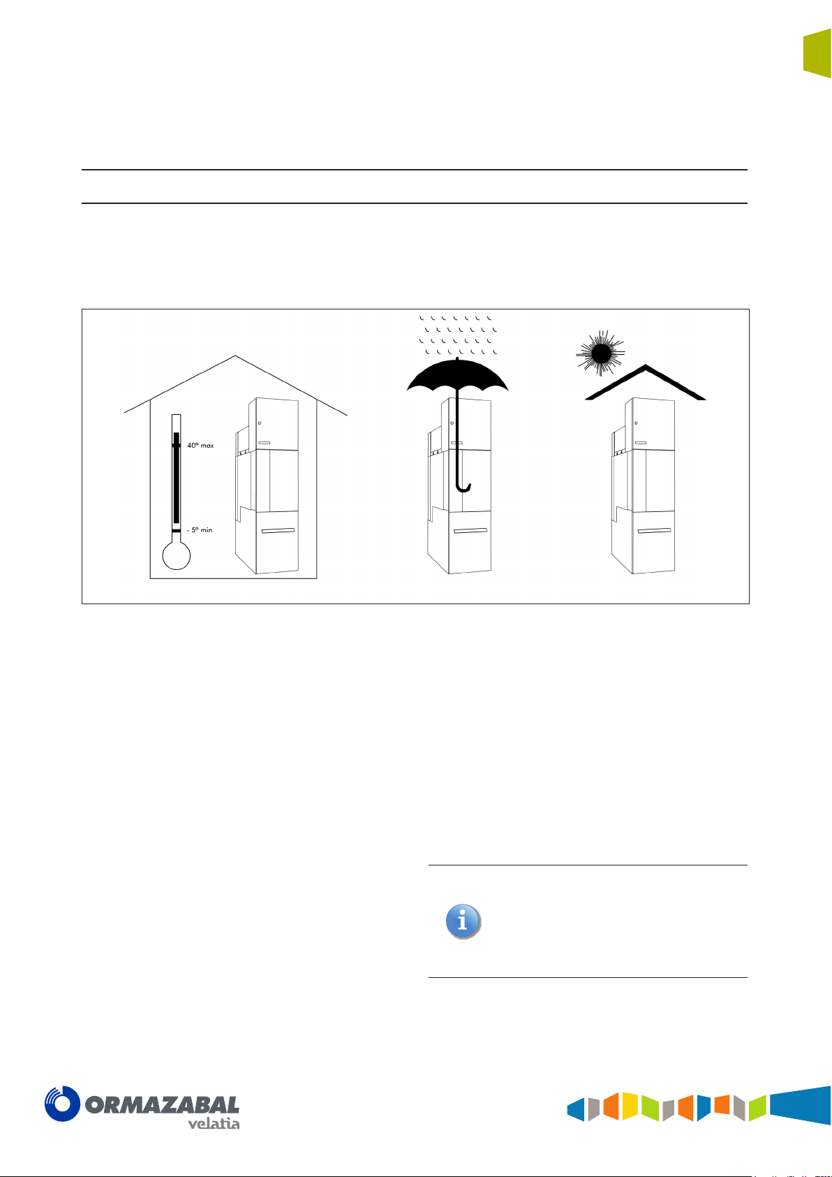
5 Storage conditions
Storage conditions
21
If it needs to be stored, the equipment must be placed on
dry ground or on top of damp-proof insulating material, still
in its original packaging.
Figure 5.1 Storage conditions detail
After prolonged storage, clean all the insulating parts
carefully before commissioning the equipment. The
enclosure should be cleaned with a clean, dry lint-free
cloth.
Storage must always be INDOORS, with the following
conditions recommended:
1. Ambient air temperature should not exceed
40 ºC and its mean value, measured in a period of
24 hours, should not exceed 35 ºC.
2. The ambient air temperature should not drop below
- 5 ºC.
3. The switchgear must be protected from direct solar
radiation.
4. Maximum altitude is 1000 m.
5. The environmental air must not have any significant
contamination from dust, smoke, corrosive and/or
inflammable gases, vapours or salt.
6. The switchgear must be protected from the rain, and
the humidity conditions should be as follows:
a) The mean relative humidity value, measured over
a period of 24 hours, must not exceed 95%.
b) The mean water steam pressure value, measured
in a period of 24 hours, must not exceed 2.2 kPa.
c) The mean relative humidity value, measured over
a period of one month, must not exceed 90%.
d) The mean water steam pressure value, measured
in a period of one month, must not exceed
1.8 kPa.
7. During transport, vibrations caused by external
factors or seismic movements must be insignificant.
Any other conditions must be notied
beforehand, since the equipment must be
factory-adjusted to the atmospheric pressure
at the nal destination or during transport.
Otherwise, the pressure switch may indicate an
incorrect value, even if the equipment's internal
gas pressure is correct.
IG-137-EN version 03; 23/06/2016
 Loading...