

Vela Argus 2000-1500, Argus Series, Argus 2000-1320, Argus 2000-1330, Argus 2000-0370-2 Developer's Manual
Page 1

Argus® Encoder Family
API Developer’s Guide
Version 2.6
Application Programming Interface Documentation
for Argus Single-Board Audio/Video Encoders
Argus Spectrum Encoding System (Model 2000-1500)
Argus 4:2:2 Encoding System (Model 2000-1330)
Argus 4:2:0 Encoding System (Model 2000-1320)
Argus LC Encoder Board (Model 2000-0370-2)
Argus Board Sets (All Models)
Vela MPEG-2 Audio/Video Encoding Systems
Release 2.6.5
Document Part Number 9050-1205
Page 2

Copyright 2003 Vela Research LP. All rights reserved.
This manual is written and published by Vela Research LP (Vela). All rights
reserved. Vela reserves the right to make changes to this manual and to the
product(s) represented without notice. No portion of this manual may be
copied, reproduced, or transcribed without the express written authorization
of Vela.
5733 Myerlake Circle
Clearwater, FL 33760-2804
Phone: (727) 507-5300
Fax: (727) 573-5310
World Wide Web – http://www.vela.com
Mailing / Shipping Address:
5733 Myerlake Circle
Clearwater. FL 33760-2804
All returns must be accompanied by an authorized RMA number obtained
from Vela.
NOTE: All trademarks, brand names or product names appearing in this publication
are registered to the respective companies or organizations that own the trademarks
or names. “Argus” and “CineView” are registered trademarks of Vela LP.
“Ligos” and “GoMotion” are registered trademarks of Ligos Corporation in the US
and/or other countries.
“RealPlayer” and “RealSystem Producer” are the registered trademarks of
RealNetworks, Inc.
“Windows Media” is a trademark of Microsoft Corporation.
Published in the United States of America June 2003
Rev. BAA-0306-016
Page 3

Table of Contents
List of Figures and Tables . . . . . . . . . . . . . . . . . . . . . . . . . . . . . . . . . . . . . . vii
Chapter 1
Getting Started. . . . . . . . . . . . . . . . . . . . . . . . . . . . . . . . . . . . . . . . . . . . . . . . . 1
Argus Single-Board Encoder Overview . . . . . . . . . . . . . . . . . . . . . . . . . . . . . . . . 1
Introduction to the Argus Encoder Family API . . . . . . . . . . . . . . . . . . . . . . . . . . . 2
For Spectrum Users. . . . . . . . . . . . . . . . . . . . . . . . . . . . . . . . . . . . . . . . . . . . . . . 2
Argus Features . . . . . . . . . . . . . . . . . . . . . . . . . . . . . . . . . . . . . . . . . . . . . . . . . . . 3
New for this Release (2.6.5) . . . . . . . . . . . . . . . . . . . . . . . . . . . . . . . . . . . . . . . . 3
Programming Changes and Version History . . . . . . . . . . . . . . . . . . . . . . . . . . . . 3
Minimum System Requirements . . . . . . . . . . . . . . . . . . . . . . . . . . . . . . . . . . . . . . 7
Software Requirements . . . . . . . . . . . . . . . . . . . . . . . . . . . . . . . . . . . . . . . . . . . . 7
Included Files. . . . . . . . . . . . . . . . . . . . . . . . . . . . . . . . . . . . . . . . . . . . . . . . . . . . 8
Component Summary . . . . . . . . . . . . . . . . . . . . . . . . . . . . . . . . . . . . . . . . . . . . 10
System Software Installation. . . . . . . . . . . . . . . . . . . . . . . . . . . . . . . . . . . . . . . . 11
Suggested Reading . . . . . . . . . . . . . . . . . . . . . . . . . . . . . . . . . . . . . . . . . . . . . . 18
ATL/COM References . . . . . . . . . . . . . . . . . . . . . . . . . . . . . . . . . . . . . . . . . . . . 18
C++ References. . . . . . . . . . . . . . . . . . . . . . . . . . . . . . . . . . . . . . . . . . . . . . . . . 18
Other References . . . . . . . . . . . . . . . . . . . . . . . . . . . . . . . . . . . . . . . . . . . . . . . 18
Customer Support. . . . . . . . . . . . . . . . . . . . . . . . . . . . . . . . . . . . . . . . . . . . . . . . 18
Chapter 2
Using the Filter Manager API . . . . . . . . . . . . . . . . . . . . . . . . . . . . . . . . . . . . 19
Component Overview . . . . . . . . . . . . . . . . . . . . . . . . . . . . . . . . . . . . . . . . . . . . . 19
The Primary Interface . . . . . . . . . . . . . . . . . . . . . . . . . . . . . . . . . . . . . . . . . . . . 19
The Secondary (Outgoing) Interface . . . . . . . . . . . . . . . . . . . . . . . . . . . . . . . . . 20
System Configuration Settings . . . . . . . . . . . . . . . . . . . . . . . . . . . . . . . . . . . . . . 20
Common Encode Parameters: The Windows Registry. . . . . . . . . . . . . . . . . . . . 21
Changing Individual Registry Settings. . . . . . . . . . . . . . . . . . . . . . . . . . . . . . . . 23
Registry-Access Methods Exposed Through Filter Manager . . . . . . . . . . . . . . 23
Filter Manager Interface Properties . . . . . . . . . . . . . . . . . . . . . . . . . . . . . . . . . . 24
Basic Filter Manager Methods . . . . . . . . . . . . . . . . . . . . . . . . . . . . . . . . . . . . . . 25
Events . . . . . . . . . . . . . . . . . . . . . . . . . . . . . . . . . . . . . . . . . . . . . . . . . . . . . . . . . 27
Other Methods . . . . . . . . . . . . . . . . . . . . . . . . . . . . . . . . . . . . . . . . . . . . . . . . . . 29
Table of Contents
Page 4

iv Argus Encoder Family Version 2.6 API Developer’s Guide
Chapter 3
Using the VTR API . . . . . . . . . . . . . . . . . . . . . . . . . . . . . . . . . . . . . . . . . . . . 31
Component Overview. . . . . . . . . . . . . . . . . . . . . . . . . . . . . . . . . . . . . . . . . . . . . 31
Windows Registry Settings . . . . . . . . . . . . . . . . . . . . . . . . . . . . . . . . . . . . . . . . 32
Creating an Instance of IVTRCenter . . . . . . . . . . . . . . . . . . . . . . . . . . . . . . . . . 32
Properties Exposed Through IVTRCenter . . . . . . . . . . . . . . . . . . . . . . . . . . . . . 33
Methods Exposed Through IVTRCenter . . . . . . . . . . . . . . . . . . . . . . . . . . . . . . 35
Component Initialization Method . . . . . . . . . . . . . . . . . . . . . . . . . . . . . . . . . . . .35
Serial Communications Port Management Methods . . . . . . . . . . . . . . . . . . . . .35
Tape Deck Control Methods . . . . . . . . . . . . . . . . . . . . . . . . . . . . . . . . . . . . . . . .35
Chapter 4
Sample Applications. . . . . . . . . . . . . . . . . . . . . . . . . . . . . . . . . . . . . . . . . . . 39
Overview . . . . . . . . . . . . . . . . . . . . . . . . . . . . . . . . . . . . . . . . . . . . . . . . . . . . . . 39
FMTestApp. . . . . . . . . . . . . . . . . . . . . . . . . . . . . . . . . . . . . . . . . . . . . . . . . . . . . 39
Overview . . . . . . . . . . . . . . . . . . . . . . . . . . . . . . . . . . . . . . . . . . . . . . . . . . . . . . .39
Creating the Project . . . . . . . . . . . . . . . . . . . . . . . . . . . . . . . . . . . . . . . . . . . . . .40
Initializing the COM libraries . . . . . . . . . . . . . . . . . . . . . . . . . . . . . . . . . . . . . . . .40
Using the #import Directive. . . . . . . . . . . . . . . . . . . . . . . . . . . . . . . . . . . . . . . . .41
The CFMInterface Class . . . . . . . . . . . . . . . . . . . . . . . . . . . . . . . . . . . . . . . . . . .42
Using the Object . . . . . . . . . . . . . . . . . . . . . . . . . . . . . . . . . . . . . . . . . . . . . . . . .44
Releasing the COM Libraries . . . . . . . . . . . . . . . . . . . . . . . . . . . . . . . . . . . . . . .47
Registering to Receive Filter Manager Events . . . . . . . . . . . . . . . . . . . . . . . . . .47
Running the Sample Application. . . . . . . . . . . . . . . . . . . . . . . . . . . . . . . . . . . . .51
Controlling the Tape Deck Between Encodes . . . . . . . . . . . . . . . . . . . . . . . . . .51
Performing an Encode . . . . . . . . . . . . . . . . . . . . . . . . . . . . . . . . . . . . . . . . . . . .51
Performing a Multi-Stream Encode (Spectrum Users) . . . . . . . . . . . . . . . . . . . .53
FMSampleAppVB. . . . . . . . . . . . . . . . . . . . . . . . . . . . . . . . . . . . . . . . . . . . . . . . 54
Overview . . . . . . . . . . . . . . . . . . . . . . . . . . . . . . . . . . . . . . . . . . . . . . . . . . . . . . .54
Adding a Reference to the API . . . . . . . . . . . . . . . . . . . . . . . . . . . . . . . . . . . . . .55
The clsFilterManagerClass. . . . . . . . . . . . . . . . . . . . . . . . . . . . . . . . . . . . . . . . .55
Using the Filter Manager Object . . . . . . . . . . . . . . . . . . . . . . . . . . . . . . . . . . . . .55
Receiving Events from Filter Manager . . . . . . . . . . . . . . . . . . . . . . . . . . . . . . . .56
RegCtrlPnl . . . . . . . . . . . . . . . . . . . . . . . . . . . . . . . . . . . . . . . . . . . . . . . . . . . . . 57
Overview . . . . . . . . . . . . . . . . . . . . . . . . . . . . . . . . . . . . . . . . . . . . . . . . . . . . . . .57
CRegistry Methods . . . . . . . . . . . . . . . . . . . . . . . . . . . . . . . . . . . . . . . . . . . . . . .57
Example: Loading an Encoder Registry Table . . . . . . . . . . . . . . . . . . . . . . . . . .58
Table of Contents
Page 5

Table of Contents v
Example: Storing Values in an Encoder Registry Table . . . . . . . . . . . . . . . . . . 59
For More Information on Registry Control . . . . . . . . . . . . . . . . . . . . . . . . . . . . . 60
RegCtrlPnl Typical Screen Shots . . . . . . . . . . . . . . . . . . . . . . . . . . . . . . . . . . . 60
Chapter 5
Distributing Components . . . . . . . . . . . . . . . . . . . . . . . . . . . . . . . . . . . . . . . 69
Overview . . . . . . . . . . . . . . . . . . . . . . . . . . . . . . . . . . . . . . . . . . . . . . . . . . . . . . . 69
Driver Installation and Registry . . . . . . . . . . . . . . . . . . . . . . . . . . . . . . . . . . . . . . 69
Encoder . . . . . . . . . . . . . . . . . . . . . . . . . . . . . . . . . . . . . . . . . . . . . . . . . . . . . . . 70
Real-Time Playback. . . . . . . . . . . . . . . . . . . . . . . . . . . . . . . . . . . . . . . . . . . . . . 70
Post-Time Playback. . . . . . . . . . . . . . . . . . . . . . . . . . . . . . . . . . . . . . . . . . . . . . 71
Microsoft Redistributable Code. . . . . . . . . . . . . . . . . . . . . . . . . . . . . . . . . . . . . . 71
Microcode Directory Structure . . . . . . . . . . . . . . . . . . . . . . . . . . . . . . . . . . . . . . 72
Argus COM Components . . . . . . . . . . . . . . . . . . . . . . . . . . . . . . . . . . . . . . . . . . 72
Spectrum Multi-Stream Encoding Files. . . . . . . . . . . . . . . . . . . . . . . . . . . . . . . . 73
Component Registration . . . . . . . . . . . . . . . . . . . . . . . . . . . . . . . . . . . . . . . . . . . 74
Appendix A
General Registry Settings. . . . . . . . . . . . . . . . . . . . . . . . . . . . . . . . . . . . . . . 75
Overview . . . . . . . . . . . . . . . . . . . . . . . . . . . . . . . . . . . . . . . . . . . . . . . . . . . . . . . 75
Standard Argus Registry Tables: . . . . . . . . . . . . . . . . . . . . . . . . . . . . . . . . . . . . 75
Argus Spectrum Registry Tables: . . . . . . . . . . . . . . . . . . . . . . . . . . . . . . . . . . . . 75
Detailed Explanation of Registry Tables . . . . . . . . . . . . . . . . . . . . . . . . . . . . . . . 76
The IBM Video Registry Table. . . . . . . . . . . . . . . . . . . . . . . . . . . . . . . . . . . . . . 76
GOP Structure and Size . . . . . . . . . . . . . . . . . . . . . . . . . . . . . . . . . . . . . . . . . . 82
The IBM Audio Registry Table . . . . . . . . . . . . . . . . . . . . . . . . . . . . . . . . . . . . . . 84
The Mux Registry Table. . . . . . . . . . . . . . . . . . . . . . . . . . . . . . . . . . . . . . . . . . . 87
The RemoteStore Registry Table . . . . . . . . . . . . . . . . . . . . . . . . . . . . . . . . . . . 91
The VTR Registry Table . . . . . . . . . . . . . . . . . . . . . . . . . . . . . . . . . . . . . . . . . . 92
The FilterMgr Registry Table . . . . . . . . . . . . . . . . . . . . . . . . . . . . . . . . . . . . . . . 96
Appendix B
Multi-Stream Registry Settings . . . . . . . . . . . . . . . . . . . . . . . . . . . . . . . . . . 99
Configuring Registry Tables for Argus
Spectrum Multi-Stream Encoding. . . . . . . . . . . . . . . . . . . . . . . . . . . . . . . . . . 99
Setting Registry for use of Second Audio Channel in Secondary Stream
(CineViewPro XL) . . . . . . . . . . . . . . . . . . . . . . . . . . . . . . . . . . . . . . . . . . . . 100
Configuring the DualEnc Registry Table. . . . . . . . . . . . . . . . . . . . . . . . . . . . . . 100
Table of Contents
Page 6

vi Argus Encoder Family Version 2.6 API Developer’s Guide
Setting the Registry for Ligos Encoding . . . . . . . . . . . . . . . . . . . . . . . . . . . . . . 102
The LigosMux Registry Table . . . . . . . . . . . . . . . . . . . . . . . . . . . . . . . . . . . . . .103
Setting the Registry for RealNetworks Encoding . . . . . . . . . . . . . . . . . . . . . . . 104
Setting the Registry for Windows Media Format Encoding . . . . . . . . . . . . . . . 106
Appendix C
Filter Manager Error/Status Codes . . . . . . . . . . . . . . . . . . . . . . . . . . . . . . 113
Index. . . . . . . . . . . . . . . . . . . . . . . . . . . . . . . . . . . . . . . . . . . . . . . . . . . . . . . 143
Table of Contents
Page 7

List of Figures and Tables
Chapter 1
Getting Started. . . . . . . . . . . . . . . . . . . . . . . . . . . . . . . . . . . . . . . . . . . . . . . . . 1
Table 1-1. Argus Encoder SDK Included Files . . . . . . . . . . . . . . . . . . . . . . . . . . 8
Figure 1-1. Installation Autorun Screen . . . . . . . . . . . . . . . . . . . . . . . . . . . . . . . 13
Figure 1-2. Installation Welcome Screen . . . . . . . . . . . . . . . . . . . . . . . . . . . . . . 14
Figure 1-3. Destination Location Screen . . . . . . . . . . . . . . . . . . . . . . . . . . . . . . 14
Figure 1-4. Select Components Screen . . . . . . . . . . . . . . . . . . . . . . . . . . . . . . . 15
Figure 1-5. Select Program Manager Group Screen . . . . . . . . . . . . . . . . . . . . . 15
Figure 1-6. Installation Start Screen. . . . . . . . . . . . . . . . . . . . . . . . . . . . . . . . . . 16
Figure 1-7. License Agreement Screen . . . . . . . . . . . . . . . . . . . . . . . . . . . . . . . 16
Figure 1-8. Password Entry Screen . . . . . . . . . . . . . . . . . . . . . . . . . . . . . . . . . . 17
Figure 1-9. Installation Complete Screen . . . . . . . . . . . . . . . . . . . . . . . . . . . . . . 17
Chapter 2
Using the Filter Manager API . . . . . . . . . . . . . . . . . . . . . . . . . . . . . . . . . . . . 19
Figure 2-1. Filter Manager Interfaces. . . . . . . . . . . . . . . . . . . . . . . . . . . . . . . . . 19
Figure 2-2. Windows Registry Transactions. . . . . . . . . . . . . . . . . . . . . . . . . . . . 21
Table 2-1. Managing Encode Parameters . . . . . . . . . . . . . . . . . . . . . . . . . . . . 22
Table 2-2. Argus Allowable State Transitions . . . . . . . . . . . . . . . . . . . . . . . . . . 25
Chapter 3
Using the VTR API . . . . . . . . . . . . . . . . . . . . . . . . . . . . . . . . . . . . . . . . . . . . . 31
Chapter 4
Sample Applications . . . . . . . . . . . . . . . . . . . . . . . . . . . . . . . . . . . . . . . . . . . 39
Figure 4-1. C++ Sample Application Window. . . . . . . . . . . . . . . . . . . . . . . . . . . 52
Figure 4-2. Visual Basic Sample Application Window . . . . . . . . . . . . . . . . . . . . 54
Figure 4-3. Registry Control Panel — IBM Video. . . . . . . . . . . . . . . . . . . . . . . . 61
Figure 4-4. Registry Control Panel — IBM Audio. . . . . . . . . . . . . . . . . . . . . . . . 61
Figure 4-5. Registry Control Panel — Mux. . . . . . . . . . . . . . . . . . . . . . . . . . . . . 62
Figure 4-6. Registry Control Panel — VTR . . . . . . . . . . . . . . . . . . . . . . . . . . . . 62
Figure 4-7. Registry Control Panel — Output. . . . . . . . . . . . . . . . . . . . . . . . . . . 63
Figure 4-8. Spectrum Registry Control Panel — IBM Video . . . . . . . . . . . . . . . 63
Figure 4-9. Spectrum Registry Control Panel — IBM Audio . . . . . . . . . . . . . . . 64
Figure 4-10.Spectrum Registry Control Panel — Mux . . . . . . . . . . . . . . . . . . . . 64
Figure 4-11.Spectrum Registry Control Panel — VTR Control. . . . . . . . . . . . . . 65
List of Figures and Tables
Page 8

viii Argus Encoder Family Version 2.6 API Developer’s Guide
Figure 4-12.Spectrum Registry Control Panel — Output . . . . . . . . . . . . . . . . . . 65
Figure 4-13.Spectrum Registry Control Panel — Multi-Encode. . . . . . . . . . . . . 66
Figure 4-14.Spectrum Registry Control Panel — Ligos . . . . . . . . . . . . . . . . . . . 66
Figure 4-15.Spectrum Registry Control Panel — RealPlayer . . . . . . . . . . . . . . 67
Figure 4-16.Spectrum Registry Control Panel — Windows Media . . . . . . . . . . 67
Chapter 5
Distributing Components . . . . . . . . . . . . . . . . . . . . . . . . . . . . . . . . . . . . . . . 69
Appendix A
General Registry Settings . . . . . . . . . . . . . . . . . . . . . . . . . . . . . . . . . . . . . . 75
Table A-1. IBM Video Registry Table . . . . . . . . . . . . . . . . . . . . . . . . . . . . . . . . 77
Table A-2. Allowable Combinations of Video Properties . . . . . . . . . . . . . . . . . 81
Table A-3. GOP Structure Examples . . . . . . . . . . . . . . . . . . . . . . . . . . . . . . . . 83
Table A-4. IBM Audio Registry Table . . . . . . . . . . . . . . . . . . . . . . . . . . . . . . . . 84
Table A-5. Mux Registry Table . . . . . . . . . . . . . . . . . . . . . . . . . . . . . . . . . . . . . 87
Table A-6. RemoteStore Registry Table. . . . . . . . . . . . . . . . . . . . . . . . . . . . . . 91
Table A-7. VTR Registry Table. . . . . . . . . . . . . . . . . . . . . . . . . . . . . . . . . . . . . 92
Table A-8. Filter Manager Registry Table. . . . . . . . . . . . . . . . . . . . . . . . . . . . . 96
Appendix B
Multi-Stream Registry Settings . . . . . . . . . . . . . . . . . . . . . . . . . . . . . . . . . . 99
Table B-1. CineView Pro XL Registry Table — Spectrum . . . . . . . . . . . . . . . 100
Table B-2. DualEnc Registry Table — Spectrum . . . . . . . . . . . . . . . . . . . . . . 101
Table B-3. LigosMpeg1 Registry Table — Spectrum . . . . . . . . . . . . . . . . . . . 103
Table B-4. RealNetworks Registry Table — Spectrum. . . . . . . . . . . . . . . . . . 104
Table B-5. WMF Registry Table — Spectrum . . . . . . . . . . . . . . . . . . . . . . . . 107
Table B-6. Table of Audio Codec Format Strings. . . . . . . . . . . . . . . . . . . . . . 110
Appendix C
Filter Manager Error/Status Codes . . . . . . . . . . . . . . . . . . . . . . . . . . . . . . 113
Table C-1. Filter Manager Error/Status Codes . . . . . . . . . . . . . . . . . . . . . . . . 113
Index. . . . . . . . . . . . . . . . . . . . . . . . . . . . . . . . . . . . . . . . . . . . . . . . . . . . . . . 143
List of Figures and Tables
Page 9

Chapter 1
Getting Started
Argus Single-Board Encoder Overview
The flagship of the Argus fleet, the Argus Spectrum Multi-Stream encoder is
capable of producing up to four encoded streams simultaneously. Typically it is
used to generate a production-quality MPEG-2 stream that corresponds to one or
more lower-bitrate streams. The Argus Spectrum encoder offers you the ability to
generate and store up to three low-bitrate streams while producing the broadcastquality MPEG-2 stream. The outcome of this process is a set of streams that represent the same content in different formats. In addition to the primary MPEG-2
stream, you may optionally create streams in Ligos
formats. Each of these secondary streams is produced by a software encoder that
compresses and stores the audio and video output of the Vela CineView
decoder. The Spectrum uses dual Intel
®
Pentium® III 866 MHz processors.
All Argus single-board encoders can add support for Spectrum multi-stream operation. Ask your Vela sales representative for details on the Spectrum option.
Ve l a ’ s Ar gu s
hosted on a Microsoft
®
4:2:2 MPEG-2 encoder is a high-end audio/video encoding system
®
Windows® 2000™ or Windows NT™ PC platform. Argus
4:2:2 uses software and hardware developed by Vela to convert traditional audio
and video signals into studio-quality MPEG-2 digital streams supporting both
Main Profile and 4:2:2 Profile encoding. The resulting MPEG-2 compressed
video can then be stored on a hard drive, and/or transferred via a network, and
will ultimately be decoded with an MPEG-2 compliant decoder, for broadcast or
personal viewing.
Controlled by the same software as the Argus 4:2:2 and Spectrum encoders, the
Argus 4:2:0 encoder supports Main Profile encoding up to 15 Mbps. As is the
Spectrum and the 4:2:2 models, the 4:20 is available in rack-mount (4-RU) or
board-only versions.
The Argus LC board-only analog encoder boasts the same high-quality MPEG-2
performance and reliability of the Argus 4:2:0 encoding system. It features
encoding rates of up to 15Mbps and supports two-channel analog audio.
®
, Real®, or Windows Media™
®
Pro
NOTE: “Argus” and “CineView” are registered trademarks of Vela LP. “Ligos” and
“GoMotion” are registered trademarks of Ligos Corporation in the US and/or other
countries. “RealSystem Producer” and “RealPlayer” are the registered trademarks of
RealNetworks, Inc. “Windows Media” is a trademark of Microsoft Corporation. All other
trademarks, brand names, or product names appearing in this publication are registered to their respective owners.
Argus Single-Board Encoder Overview
Page 10

2 Argus Encoder Family Version 2.6 API Developer’s Guide
Vela manufactures the single-board PCI encoder used in all Argus encoders. The
board features an IBM
®
MPEG-2 encoder chipset to compress and encode video
data received from composite or digital sources. In addition, two digital signal processors compress and encode up to four channels of digital or analog audio.
Vela’s popular CineView
®
Pro decoder is included in the Argus 4:2:2 encoder for
real-time or post-production playback of the encoded MPEG stream. The Argus
4:2:0 encoder uses the analog-only CineView Pro LE decoder for playback purposes. CineView decoders are available as an extra-cost option for the Argus LC
board-only encoder.
This manual is delivered to users of the Argus Spectrum, 4:2:2, 4:2:0, and LC
models. Unless there is a note to the contrary, you should assume that the information and instructions in this document apply equally to all encoder models. The
product name “Argus” is used interchangeably throughout this manual among the
models. In the absence of a note to the contrary, you should assume that such
references apply to all models of the single-board Argus encoder family.
Introduction to the Argus Encoder Family API
The Application Programming Interface (API) for the Argus family of singleboard encoders was designed using an object-oriented approach. Each core function of the encoder has its own COM (Microsoft’s Component Object Model)
component associated with it. A complete encode on the Argus is accomplished
when these components are used together and accessed through the Filter Manager, Vela's single, well-defined COM interface to the Argus encoder. The Filter
Manager is responsible for managing an encoding session from the reading of the
Windows Registry settings to the storage of the last byte of encoded material. As
a developer, you need to initialize, cue, start, stop, pause, and resume only. The
Filter Manager handles the rest.
For Spectrum Users
Spectrum users should note that, if you have already developed a software application for the standard Argus encoder, the good news is that you won't need to do
much programming to turn on multi-stream encoding. The sample application for
the Argus Spectrum is the same one that we use for the standard API. In fact, all
that you really need to do is to make some adjustments to the Windows Registry,
toggling a flag to turn on each of the secondary streams, then setting the encoding
parameters for that stream. In Appendix B you will find a detailed description of
each of the Registry tables that are used specifically to configure the encoder for
multi-stream encoding.
Introduction to the Argus Encoder Family API
Page 11

Chapter 1 — Getting Started 3
You'll probably find it helpful, too, to look over our user's guide, the Argus
Encoder Family Version 2.6 Installation and User Manual, which describes the
operation of the various Argus encoders. Among other topics, it includes a discussion of the Spectrum’s Aladdin HASP
®
software protection key (“dongle”), that
grants or denies permission to use each of the multi-stream encoding components.
As mentioned earlier, you have the option of turning on one, two, or all three of
the optional secondary streams, assuming that the HASP device attached to the
encoder grants permission to use them. You should keep in mind, though, that
each of the secondary encoders requires additional processing power. You may
find that running all three of the low-bitrate encodes at once pushes your CPU
usage prohibitively high. As you experiment with the multi-stream encoding
option, remember that you can reduce the CPU usage of any one of the lowbitrate encoders by decreasing its horizontal and vertical resolutions and by
decreasing its bit rate. Of course, if you decrease the mux rate (or video bit rate)
of the primary stream, you'll also reduce CPU usage. Observing the Windows
task manager as you encode should help you to determine the ideal settings for
your customized multi-stream encoder.
Argus Features
New for this Release (2.6.5)
• Upgraded the WMF Registry Table to support Microsoft Windows Media
version 9 (Spectrum users only).
Programming Changes and Version History
The API for Argus version 2.6 is based on the same easy-to-use COM interface
that was introduced in version 2.2 of the Argus encoder software. Because we
made very few changes to the FilterManager interface, you will not need to
extensively modify your existing applications when you upgrade to version 2.6.
Release 2.6.3 featured the following changes and enhancements:
• Allows unconditional operation, including Dolby AC-3 encoding, under
Windows 2000. This fixes a performance issue in Release 2.6.2.
• The Momentum software was upgraded, allowing the user to perform AC3
encodes on a Windows 2000 system.
• In previous releases, when the Adjust-GOP-Time-Code option was turned
on during a “seamless” pause/resume encode, the first GOP header after
each resume was not being stamped, so the time code in that GOP header
Argus Features
Page 12

4 Argus Encoder Family Version 2.6 API Developer’s Guide
would be set to 00:00:00:00. Now the first GOP header, like all other headers, is properly stamped.
• Using EDL Editor, the user may now turn on the Adjust-GOP-Time-Code
option when performing a seamless pause/resume encode.
• The software for the Adjust-GOP-TC feature was improved for accuracy and
efficiency.
• By using the Mux table key “PcrFrequency,” the user can now set the transport-stream PCR frequency. Use a setting of 50 for standard encodes, of 20
for DVB-type encodes.
• Changes to the VTR and FilterManager code guarantee frame-accuracy for
encodes that include two audio streams as well as for single-audio encodes.
• The AC3 code was modified to guarantee that the user-adjustable Dolby
delay works properly for the first and subsequent clips.
• The IBMVideo software was modified so that it does not include a user-data
field if closed captioning is turned off.
Release 2.6.2 contained the following changes and enhancements:
• If you have purchased the required hardware, you may now include embedded audio in your encoded stream. Just set the Audio Input Type to “3.”
• Using the new Pause/Resume mode, you may now include more than three
segments in your encoded clip. Each segment will begin on the mark-in that
you specify in the Registry. To use the new Pause/Resume feature:
1. In the VTR Registry table, set the “Number of Segments” key to 0 (zero),
then set the mark-in and mark-out points. Do this before calling Cue().
2. In the Pause event handler, write to the VTR Registry the mark-in and
mark-out points for the next segment.
3. Call Resume() to encode the next segment.
4. To end the encode, call Resume(), then Stop().
5. Check the “Seamless Pause” box if you are planning to pause/resume
while encoding Dolby/AC-3 audio data to guarantee audio/video synchronization. In fact, even if you are not performing an AC-3 encode, you may
enable this option to gain improved A/V synchronization.
Release 2.6.1 introduced the following changes and enhancements:
• Improved reliability and efficiency: audio channels 3 and 4 start more reliably; the cue process takes less time; and Filter Manager automatically
detects and sets drop-frame mode if VTR control is enabled.
• If you have purchased the required hardware and additional software, you
Argus Features
Page 13

Chapter 1 — Getting Started 5
can now encode a Dolby* Digital (AC-3) stream in your primary MPEG
stream. For more information, contact your Vela sales representative and ask
about AC-3 encoding.
• You may now select four-channel audio encoding in combination with multistream encoding. Spectrum users note that just one audio stream will be
included in the secondary stream. Also of interest to Spectrum users is the
fact that software supporting the production of Real and Windows Mediaformatted secondary streams has been modified for optimum quality
and performance.
• If you are using the 4:2:2 chroma option, you may now elect to turn VBI
encoding off. Prior to Release 2.6.1, the resolution was forced to 720/512 (or
720/608 for PAL) if the 4:2:2 option was enabled.
• Under special circumstances, you may specify that the first line of encoded
video for a non-VBI encode will be line 21 (instead of the standard line 22).
This change should be made only if for some reason you are unable to perform VBI encodes and are also unable to accept the common practice of
including closed caption data in the MPEG user-data field.
• You may elect to turn off all audio channels, encoding only video (or, with
special hardware and software available from Vela, encoding only video plus
a single Dolby Digital/AC-3 stream).
The initial 2.6 release introduced the following changes to FMTestApp:
• We removed an unnecessary call to
• We set m_bErrorFlag to TRUE if
Reset() from the OnInitialize() method.
Cue() fails.
The previous release, version 2.5, included the following changes from 2.4:
• After a lengthy WMF or Real G2 encode, Filter Manager now sends log
events with an error code of 99 to indicate the status of the indexing process.
You may want to filter these out of the log file.
• You should remove the
VTRDisconnect() method from the error-event and
finished-event handler of the client application.
• There is a new boolean property exposed by the Filter Manager interface
called Transcode. The transcode feature is not currently supported, and the
property should be set to FALSE.
• We changed the
AfxGetInstanceHandle())
when
_Module.Term() is called.
_Module.Init(NULL, NULL) call to _Module.Init(NULL,
. This change allows a more complete clean-up
*Dolby is a trademark of Dolby Laboratories.
Argus Features
Page 14

6 Argus Encoder Family Version 2.6 API Developer’s Guide
•In the OnError() event handler, we added the line:
pView->m_bErrorFlag = true;
to replace the earlier code (shown on next page):
if(bErrorFlag)
*bErrorFlag = true;
This change guarantees that all of the components will reset before the next cue if
the previous encode failed.
Changes made in version 2.4 to our C++ sample application include:
• We removed the
MessageBox() calls from the OnLog() and OnError() event
handlers, since they tend to lock up the encoder.
• We enable the reset button when the encoder falls into an error state.
• There is a boolean property exposed by the Filter Manager interface called
Transcode. Because the transcoding process is not currently supported, you
should not use the
• Note that you should remove the
PutTranscode() method except to set the property to zero.
VTRDisconnect() method from the error-
event and finished-event handler of your client application.
Version 2.3 changes included the following:
• Most of the properties exposed by FilterManager can now alternatively be
set using the Windows Registry. We recommend that you use the Registry
settings instead of the property Put and Get methods, which will be removed
in future interfaces. Refer to Appendices A and B for complete listings and
descriptions of Argus Registry settings.
• Similarly, the properties that were once defined in ArgusConfig.txt (using
the CFInterface application) are now set using the Windows Registry.
• A number of database-related methods were added to the FilterManager
interface so that it can be used by our standard Argus application, EDL
Editor. As a result of these interface changes, you no longer need to register
a separate set of COM components in order to run EDL Editor. Additionally,
when you encode using EDL Editor, you'll see that it creates and updates
Windows Registry tables identical to those used by the sample application
that we provide with the SDK. These changes should make it easier for you
to compare the functionality of your application with that of our standard
application, a definite advantage in debugging. Please do not use the new
database-related methods in your application, as they will not be supported
in future releases.
• For easier debugging, the list of defined error codes has been expanded and
Argus Features
Page 15

Chapter 1 — Getting Started 7
the precision of FilterManager's error-reporting has been improved.
•The
Load() and Save() methods no longer accept an argument (they used to
require a VTR_Enabled argument).
• In the CRegistry class
SetValue() method, the second argument is no longer
a pointer; you should remove the ampersand from the second argument of
each call to
SetValue(). See “CRegistry Methods,” page 57, for further
explanation of the changes made to the sample application.
• Spectrum users note: If you were using the version 2.2 Ligos dual-encode
option, you'll find that the required settings in both the DualEnc and the
LigosMpeg1 Registry tables have changed. Many of these changes were made
to accommodate multi-stream encoding using Real and Windows Media™
formats. Please refer to Appendix B for a complete list of Argus Spectrum
multi-stream encoding Registry settings.
Minimum System Requirements
• Microsoft® Windows® 2000 (Service Pack 2) or Windows NT™ 4.0 operating system (Service Pack 6a).
®
•IBM
• 256 MB RAM
• CD-ROM drive (for installation of system files)
• Vela Argus encoder system or encoder board
• Vela CineView Pro (for Argus 4:2:2 and Spectrum) or Pro LE (for Argus
• 9.0 GB hard drive (fast/wide SCSI)
• Aladdin HASP
PC or PC-compatible Pentium® III dual-processor (866 Mhz each)
system with PCI bus
4:2:0 and LC) PCI/VGA decoder board
®
software protection key (“dongle”), programmed to enable
the multi-stream encoding options that you have purchased. This device is
supplied when you purchase the Argus Spectrum.
Software Requirements
• Standard Vela system software, version 2.6 or higher
• Argus Encoder Software Developer’s Kit (SDK), version 2.6.
• Compiler with COM support: Microsoft Visual C++™ 6.0 (Service Pack 4 or
higher) with Unicode support; or Visual Basic™ 6
Minimum System Requirements
Page 16

8 Argus Encoder Family Version 2.6 API Developer’s Guide
Included Files
The following table is a list of all files to be installed with the standard EDL
Editor installation and with the installation of the Argus Encoder SDK. (Those
that are installed as part of the SDK are located in the folder
Vela Research\Argus\ SDK
Argus SDK Included Files (includes Spectrum files)
Filename File Description Folder
or in one of its sub-folders.)
C:\Program Files \
Velasbe.sys The encoder kernel mode device driver
Velaencd.sys The encoder kernel mode device driver
AsfEncodeU.dll
AsfWriterU.dll
CinProSerComU.dll
FilterManagerU.dll
IBMAudioU.dll
IBMVideoU.dll
Export.dll
LigosEncodeU.dll
MultiplexU.dll
RemoteStoreU.dll
RealEncode.dll
VTRControlU.dll
MemoryManager.dll
MemMgrServer.exe
Vela_Pins.dll
EDLEditor.exe
EDLEditor.hlp
EDLEditor.cnt
Xpx4032.ocx
XgridAll.reg
Film_1.ico
eula.txt End-user license agreement for EDL
for Windows 2000.
for Windows NT.
Argus COM components, including
those for Spectrum multi-stream use.
For CineView Pro/Pro LE components,
refer to the CineView Pro/Pro LE Instal-
lation/User Manual and API Guide.
Server executables required to communicate with CineView Pro decoder.
Standard encoder GUI executable and
associated files.
Editor.
C:\Winnt\System32\Drivers
C:\Winnt\System32\Drivers
C:\Program Files\Vela
Research\Argus
C:\Program Files\Vela
Research\Common
C:\Program Files\Vela
Research\Argus
C:\Program Files\Vela
Research\Argus
Table 1-1. Argus Encoder SDK Included Files
Software Requirements
Page 17

Chapter 1 — Getting Started 9
Argus SDK Included Files (includes Spectrum files) (Continued)
Filename File Description Folder
sdk.txt Argus SDK license agreement C:\Program Files\Vela
RegCtrlPnl.exe
RegCtrlPnl.ico
FilterManager.tlb Type library for Filter Manager COM
Vtr.tlb Type library for the VTR COM compo-
VTRU.dll Argus SDK COM component required to
FMSampleAppVB
Associated source code
FMTestApp.dsp
Associated source code
RegCtrlPnl.dsp
Associated source code
VTRTestApp.dsp
Associated source code
FMTestApp.exe Build of FMTestApp work space. Allows
RegCtrlPnl.exe Build of RegCtrlPnl work space. Allows
Application for editing encoder parameters in Windows Registry.
component.
nent (an auxiliary component that can be
used to control the VTR when there is
not an encode in progress).
use standalone VTR software.
Source code for Visual Basic sample
application that drives the encoder.
Work space containing source code for
the C++ sample application that drives
the encoder.
Work space containing source code for
the C++ sample application that manages the encoder Registry settings.
Work space containing source code for
the Visual C++ sample application that
controls a tape deck (its commands can
be used when the application is not in
the process of encoding).
user to test sample application without
building it.
user to test application without building it.
Research\Argus\SDK
C:\Program Files\Vela
Research\Argus
C:\Program Files\Vela
Research\Argus\SDK\
TypeLibs
C:\Program Files\Vela
Research\Argus\SDK\
TypeLibs
C:\Program Files\Vela
Research\Argus\SDK
C:\Program Files\Vela
Research\Argus\SDK\
FMSampleAppVB
C:\Program Files\Vela
Research\Argus\SDK
\FMTestApp
C:\Program Files\Vela
Research\Argus\SDK\ RegCtrlPnl
C:\Program Files\Vela
Research\ Argus\SDK\ VTRTestApp
C:\Program Files\Vela
Research\ Argus\SDK
C:\Program Files\Vela
Research\Argus\SDK
Table 1-1. Argus Encoder SDK Included Files (Continued)
Software Requirements
Page 18

10 Argus Encoder Family Version 2.6 API Developer’s Guide
Argus SDK Included Files (includes Spectrum files) (Continued)
Filename File Description Folder
Jet40sp3_comp.exe
Mdac_typ.exe
Wininet System DLL required to support
Sbe.exe (Win 2K)
Sbencode.exe (Win 2K)
Sbetest.exe (Win 2K)
Encode.exe (Win NT)
Ibmtest.exe (Win NT)
Vt32s.exe (Win NT)
Various System DLLs for ATL and MFC. C:\Winnt\System32
Table 1-1. Argus Encoder SDK Included Files (Continued)
Executables that can be used to install
the latest version of the ODBC DLLs
required to run EDL Editor, version 2.6.
RemoteStore component.
Applications that can be used to diagnose problems with encoder hardware
or microcode. Used with Windows 2000.
Applications that can be used to diagnose
problems with encoder hardware or
microcode. Used with Windows NT 4.0.
C:\Program Files\Vela
Research\Argus\Mdac
C:\Winnt\System32
C:\Program Files\Vela
Research\Argus\Diags
C:\Program Files\Vela
Research\Argus\Diags
Component Summary
The goal of this API set is to give you, the developer, a binary-independent,
easy-to-control interface to the Argus encoder family. We have implemented the
encoder software on the Windows 2000 and NT platforms as a set of COM
(Component Object Model) components. Using version 2.3 or later of the API,
you are required to create only a single COM object, one derived from the FilterManager interface. FilterManager, in turn, controls all of the subordinate
COM components for you.
In preparing to encode a clip, your application must set a number of encoding
parameters. In earlier versions of the Argus API, these parameters were set using
a combination of three methods: by loading from the Windows Registry, by reading from the ArgusConfig.txt configuration file, and by calling a
method. In version 2.3 and later versions of the API, you can (and should)
Put()
set all encoding properties through the Windows Registry. (See Appendices A and
B listings of Argus Registry keys.)
FilterManager
FilterManager
The FilterManager interface is easy to use, exposing just a handful of core methods or commands: Initialize, Load, Cue, Start, Stop, Pause, Resume, and Reset.
Software Requirements
Page 19

Chapter 1 — Getting Started 11
Each of these basic commands, explained in detail later in this manual, triggers
the start of a specific phase of the Argus encoding process.
To establish the parameters under which the encode is to operate, you will set
Argus-specific Windows Registry keys, grouped by core functionality in tables.
See Appendix A for general, non-Spectrum Registry tables.
See Appendix B for Spectrum multi-stream Registry tables.
You can set the Registry keys in one of two ways:
• By using the RegCtrlPnl application, a GUI-based application with a tab for
each of the Windows Registry tables used by the Argus encoder.
• Programmatically, by using the CRegistry class (or your own software) to
write to the Windows Registry. This second method is useful for changing
the values of keys that must be reset with each encoding session (the name
of the output file, for example).
VTR
In addition to the FilterManager API, the Argus Encoder 2.6 SDK includes an auxiliary API that can be used to control a tape deck when an encoding session is not in
progress. This second component, VTR.DLL, is described fully in Chapter 3.
Self-Registration
The COM components that drive the Argus encoder are all self-registering. The
Argus installation program registers each component using REGSVR32.EXE, a
utility that is included with the Argus API. This same utility can be used to
remove components from the Registry, to add new components, or to replace
existing components with newer versions.
System Software Installation
Note that the installation of the Argus Encoder Software Developer’s Kit is a
password-protected process. Included with the SDK is an authenticated password that allows installation of the SDK and accompanying files. If you did not
receive a password with your SDK purchase, contact Vela Support.
If a previous version of Argus encoder system software is installed on your system, it must be uninstalled before continuing with the installation of the version
2.6 SDK. Use the Windows Control Panel “Add/Remove Programs” function to
uninstall Argus software, if necessary.
If you have not already installed version 2.6 of the Argus system software, please
refer to the Argus/CineView Pro installation instructions for Windows NT or
System Software Installation
Page 20

12 Argus Encoder Family Version 2.6 API Developer’s Guide
Windows 2000 to install the software before continuing. See the appropriate
product installation and user manual that came with your encoder for complete
instructions.
If you have already installed version 2.6 of the Argus software on your system,
but did not check the “Argus SDK” during the first installation, you can install it
at this time.
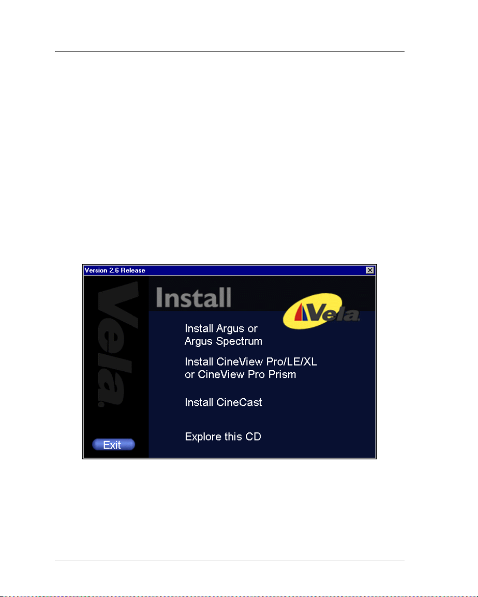
To begin the installation, simply insert the Argus system software CD-ROM and,
from the Autorun setup screen (Figure 1-1), select “Install Argus or Argus
Spectrum”, and follow the steps below:
1. Read the “Welcome” screen (Figure 1-2), then click Next.
2. On the “Choose Destination Location” screen (Figure 1-3), accept the
C:\Program Files\ Vela Research destination, as listed, by clicking Next.
Do not change the destination, as it is important for proper system operation.
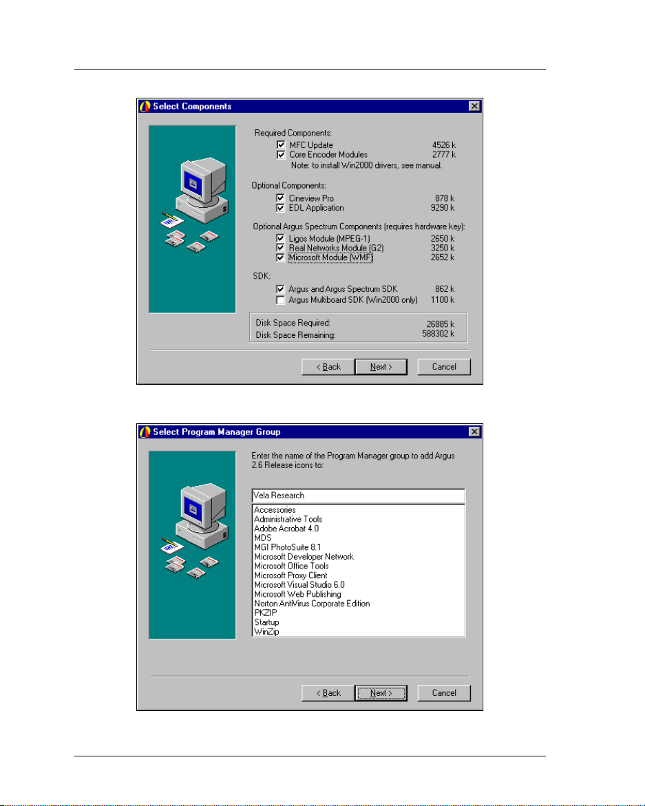
3. On the “Select Components” screen (Figure 1-4):
• Under SDK, check the “Argus and Argus Spectrum SDK” check box.
(Because it is password-protected, you will be able to install the SDK only if
you purchased it and received the corresponding password. If you cannot
locate the password, call Vela Support for assistance.)
• If you have not already done so, you must run the “MFC Update” and
“Core Encoder Modules” (under Required Components on the “Select
Component” screen). These two check boxes must always be checked to
insure proper installation of the SDK software.
• Click Next to proceed with the installation of the selected components.
4. From the “Select Program Manager Group” screen (Figure 1-5), accept “Vela
Research” by clicking Next.
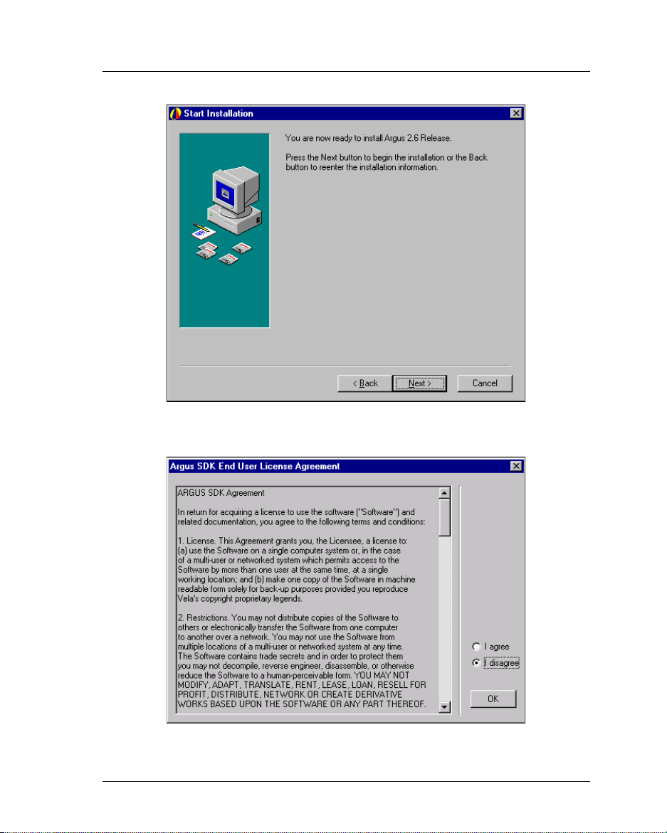
5. On the “Start Installation” screen (Figure 1-6), click Next.
• A “DO NOT REMOVE THE CD” screen will display as a reminder that a
number of reboots may be required during the installation process, click OK.
• If you have chosen to run the MFC Update option, the installation process
will begin here to copy files.
• An “Install” message box will appear advising that the system must be
restarted. Click OK, and then wait as the system reboots. Leave the CD-
ROM disc in the drive through the restart process.
6. If you remembered to leave the CD-ROM in the drive, the setup application
pops up immediately after the system reboot. Continue with the installation by
following these steps:
System Software Installation
Page 21
Chapter 1 — Getting Started 13
• Select the “I Agree” radio button on the “Argus SDK End User License
agreement” screen (Figure 1-7). Click OK.
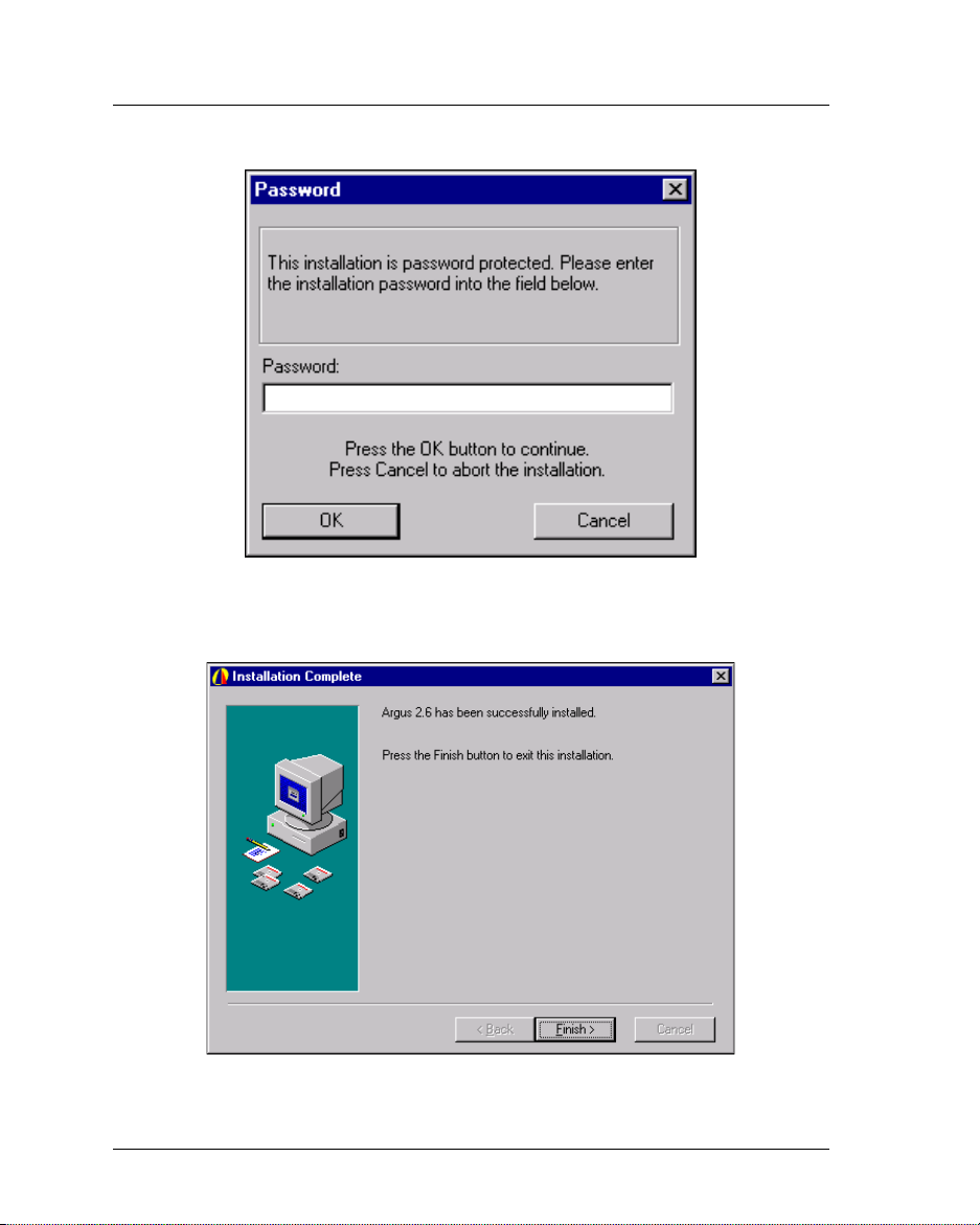
• On the “Password” screen (Figure 1-8), you will be asked for a password.
Use the one supplied with your Argus SDK. If you have problems finding
your password, contact Vela Support (see page 18). After entering the password, click OK.
• At this time, the application will install some files.
7. On the “Installation Complete” screen (Figure 1-9), note that Argus 2.6 has
been successfully installed. Click Finish.
8. The “Install” message box will appear advising that the system must be
restarted. Click OK then let the system reboot. Leave the CD-ROM disc in the
drive through the system restart process.
9. After the system has rebooted, close the setup application if it is active, then
remove the CD-ROM disc from the drive.
Figure 1-1. Installation Autorun Screen
System Software Installation
Page 22

14 Argus Encoder Family Version 2.6 API Developer’s Guide
Figure 1-2. Installation Welcome Screen
Figure 1-3. Destination Location Screen
System Software Installation
Page 23
Chapter 1 — Getting Started 15
Figure 1-4. Select Components Screen
Figure 1-5. Select Program Manager Group Screen
System Software Installation
Page 24
16 Argus Encoder Family Version 2.6 API Developer’s Guide
Figure 1-6. Installation Start Screen
Figure 1-7. License Agreement Screen
System Software Installation
Page 25
Chapter 1 — Getting Started 17
Figure 1-8. Password Entry Screen
Figure 1-9. Installation Complete Screen
System Software Installation
Page 26

18 Argus Encoder Family Version 2.6 API Developer’s Guide
Suggested Reading
This manual assumes that you are familiar with ATL, COM, and C++ (or Visual
Basic) programming. For more information on these topics, we recommend that
you refer to the following publications.
ATL/COM References
Inside COM, Rogerson; Microsoft Press. Recommended for COM introduction.
Covers COM programming explicitly from a C/C++ hard-core, low-level mode.
ATL Internals, Rector and Sells; Addison-Wesley. This is an excellent reference
for ATL programming using Visual Studio 6.0. It includes very useful sections on
Smart Pointers, BSTRs, and events.
ATL COM, Grimes, Stockton, Reilly, and Templeton; WROX Press. This book
delves deep into the heart of the Active Template Library. Primarily deals with
server-side issues, but has some client code development considerations as well.
C++ References
The C++ Programming Language, Stroustrup. This bottom line reference on the
C++ programming language is highly recommended for the serious developer.
Using Visual C++, Gregory; QUE Publishing. A comprehensive reference for
Microsoft’s VC++ compiler.
Other References
References on the Sony® 9-Pin Protocol, used for VTR machine control, are
available on the Internet or by contacting Sony Broadcast and Professional
Company (Division of Sony Corporation).
Customer Support
In the event of questions or problems with Vela Application Programming
Interface methods, materials, or this manual, do not hesitate to contact
Vela Training and Support as follows:
• Phone: (727) 507-5301
• E-mail: support@vela.com
• World Wide Web - http://www.vela.com
Suggested Reading
Page 27
Chapter 2
Using the Filter Manager API
Component Overview
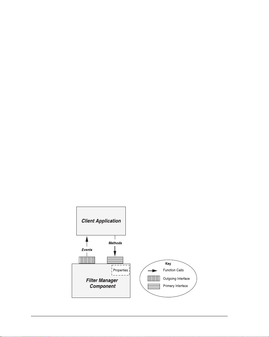
The key element of the Argus encoder API is the Filter Manager COM
component, which offers two custom interfaces. The primary interface allows
your application to make requests of the Filter Manager. The second custom
interface (the outgoing interface) allows the Filter Manager to send COM
events to your calling application. Note that both Filter Manager interfaces
use Unicode-style character strings.
The Primary Interface
The primary Filter Manager interface exposes methods that service requests for
encoder functionality. Specifically, it accepts requests to initialize and reset the
encoder software, as well as requests to cue, start, stop, pause, and resume an
encoding session. Additionally, it exposes methods to read hardware and firmware version numbers, to calculate useful time codes, to track the status and
progress of an encode, and to connect and disconnect from the serial port
through which the VTR is controlled.
Through its primary interface, the Filter Manager component exposes methods
and properties. If you are unfamiliar with methods and properties, or with other
aspects of object-oriented programming, take time to review reading material on
C++ or COM. Refer to the end of Chapter 1 for some suggestions.
Figure 2-1. Filter Manager Interfaces
Component Overview
Page 28

20 Argus Encoder Family Version 2.6 API Developer’s Guide
A method is simply a function call. Usually this function performs an operation,
then returns a status code. Each of the fully supported Filter Manager methods
is defined in this manual. The definition includes a description of the operation
that the method performs as well as a list of the possible return values. Be sure
to check the return value of any method that you call before proceeding with the
encoding process.
Similar to a C++ class data member, a property has a value or a setting.
Typically the value of a property can be set by calling a specific
Put() method
exposed by the Filter Manager interface. Likewise, its value can be retrieved with
a
Get() method. However, beginning with version 2.3, we concentrate more on the
Windows Registry and less on COM properties to set and retrieve encoding
parameters. In fact, Filter Manager now exposes just five fully supported properties (see “Filter Manager Interface Properties,” page 24).
The Secondary (Outgoing) Interface
Through its outgoing interface, the Filter Manager component implements events.
An event is a COM mechanism that allows the component to send messages to
the calling application. Filter Manager uses events to issue Log messages, Error
messages, Pause/Resume messages, and Finished messages to the client application. The client can register to receive these messages, at your discretion.
The remainder of this chapter describes techniques of setting encoding parameters for the Argus encoder. Additionally, it defines and describes each of the basic
encoding commands exposed through the primary Filter Manager interface.
System Configuration Settings
During the initialization process, the Filter Manager interface checks the Windows Registry to determine if two specific standard components should be
loaded: one that controls the CineViewPro decoder and another that controls a
VTR. Typically, you will use Argus software to control your tape deck. However,
you may configure your application to bypass the Argus VTR-control software
or to run without the CineView Pro decoder. Spectrum users should note that the
Argus Spectrum must be configured to run with the CineView Pro decoder.
The Windows Registry table
Broadcast Argus\EncoderConfig
stalled,” both of which have default values of 1. To disable the CineView Pro
decoder (for non-Spectrum users), change the value of the DecoderInstalled key
to 0 before running your application. Likewise, to disable the Argus VTR software, change the value of the VtrInstalled key to 0. Again, for proper operation,
System Configuration Settings
HKEY_CURRENT_USER\Software\Vela Research\
has two keys, “DecoderInstalled” and “VtrIn-
Page 29
Chapter 2 — Using the Filter Manager API 21
Spectrum users must not disable the CineView Pro decoder.
Note that if you disable the CineView Pro decoder, you will not be able to
perform real-time confidence monitoring. If you disable the Argus VTR
control software, you may sacrifice frame-accurate starts.
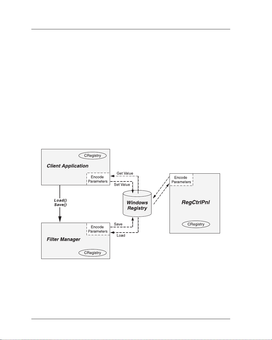
Common Encode Parameters: The Windows Registry
Applications based on version 2.4 or later of the Argus software use the Windows
Registry exclusively to store and retrieve parameters for an encoding session.
Although previous versions of Argus software used the Registry to some extent,
they still relied on the ArgusConfig.txt configuration file and on a handful of
COM
Put() methods to set a few exceptional encoding parameters. Now all
encoding parameters can (and should) be stored in and loaded from the Registry.
Figure 2-2 illustrates typical interactions between Argus-related software and the
Windows Registry.
Figure 2-2. Windows Registry Transactions
One useful feature of the Registry method of storing encoding parameters is that it
is not necessary to set up the Registry before the first encode. If the application
attempts to load from the Registry when there are no encode settings there, Filter
Manager responds by saving all of the default settings to the Registry, creating all of
Common Encode Parameters: The Windows Registry
Page 30

22 Argus Encoder Family Version 2.6 API Developer’s Guide
the needed keys. You can then programmatically or manually (using Microsoft's
regedt32 or regedit tool) change Registry settings before subsequent encodes.
All of the Argus Registry settings are stored in one of 12 Registry locations
under
HKEY_CURRENT_USER\Software\Vela Research\Broadcast Argus.
These sub-locations are: “EncoderConfig,” “FilterMgr,” “IBM Audio”
“IBM Video,” “Mux,” “RemoteStore,” “VTR,” “DualEnc,” “LigosMpeg1,”
“LigosMux,” “RealNetworks,” and “Wmf.” Appendix A identifies and
describes in detail each of the general Registry settings that support the
single-board Argus, while Appendix B lists specific Registry settings for
the Argus Spectrum multi-stream encoding process.
There are a number of circumstances under which you may need to access the
encoding parameters that are stored in the Windows Registry. As shown in
Table 2-1, the Argus SDK provides a variety of tools to assist with the task of
managing these encoding parameters.
Task Tool Description
Review, modify, save the full set of
parameters through an application
other than the user interface to the
encoder.
Change individual Registry settings
(i.e., file name, mark-in) before
starting an encode.
Display a specific set of encode
parameters through the user interface to the encoder.
Load the full set of encoding
parameters from the Windows
Registry in preparation for an
encode.
Save the full set of encoding
parameters under which Argus is
currently encoding.
RegCtrlPnl An application that displays all of the
CRegistry class,
SetValue() method
CRegistry class,
GetValue() method
FilterManager
Load() method
FilterManager
Save() method
Table 2-1. Managing Encode Parameters
Common Encode Parameters: The Windows Registry
encoding parameters, allowing the user
to review and modify them. Source code
is provided with the SDK. See page 57.
The CRegistry class, whose source code
is provided with the RegCtrlPnl application, provides easy-to-use GetValue()
and SetValue() commands to manage
encoding parameters of all data types.
Loads all of the encode parameters from
the Registry into the specific encoder
COM components to which the parameters apply.
Dumps all of the encoding parameters
currently in memory out to the
Windows Registry.
Page 31

Chapter 2 — Using the Filter Manager API 23
Changing Individual Registry Settings
The production release of version 2.6 of the Argus SDK contains source code for
a sample application that illustrates the loading, modification, and saving of each
of the individual Registry settings. This source code is installed in the
Files\Vela Research\Argus\SDK\RegCtrlPnl
folder. You'll probably find that you
C:\Program
can set most of the encoding properties once using a Registry editing tool like the
RegCtrlPnl application, then leave the settings untouched.
However, a few properties (for example, the output file name and the VTR
mark-in and mark-out) are likely to change with each encode. Using the source
code of the RegCtrlPnl application as an example, you can programmatically
change these settings before loading and cueing for each encoding session.
RegCtrlPnl includes source code for a Registry-management class, CRegistry,
that makes it easy for you to access and change Registry settings.
Registry-Access Methods Exposed Through Filter Manager
The Filter Manager interface exposes a Load() method that loads the full set of
encode parameters from the Registry into memory, as well as a
that writes all of the encoder's current property settings to the Registry. Before
calling the FilterManager
Cue() method to set up for an encode, you should first
write to the Registry any individual property changes that you need to make, then
Load() to load all of the encoder settings into memory. Refer to the source
call
code of our sample application, FMTestApp, for an example. You can preserve
the current encoder settings by calling
Save() with each encode.
long Load() – Loads all of the settings from the Registry locations listed above,
except for those in the EncoderConfig table (this table is read once only, during the Filter Manager initialization process). If the Registry does not yet
exist, the
Load() call creates it, enters all of the Registry keys, and assigns
their default values.
Note that the
The
Load() method returns 0 if it successfully loads encoding parameters from
Load() method no longer takes an argument, as it did in version 2.2.
the Registry. If it fails, it returns a negative number defined in Appendix C.
long Save() – Saves to the appropriate Registry keys all of the encoding parame-
ters that are currently in memory, except for those in the EncoderConfig table.
It returns 0 if the save procedure finished successfully or a negative error code,
defined in Appendix C, if the procedure was unsuccessful.
Save() method
Common Encode Parameters: The Windows Registry
Page 32

24 Argus Encoder Family Version 2.6 API Developer’s Guide
Filter Manager Interface Properties
Because the Windows Registry is now used to store all of the encoding parameters, the list of Filter Manager interface properties defined in this section is short.
In fact, it includes only those properties that report on the version numbers of
installed hardware and firmware, those that report on the progress or status of an
encoding session, and those that toggle on and off specific Windows functionality.
Listed below are the Filter Manager interface properties that are fully supported
in version 2.6. Though a number of previously used properties may still appear in
the Filter Manager interface, you should assume that properties not defined below
are not fully supported.
Before defining the property, each listing specifies whether the
the
Put() method is implemented for that property. In each of the definitions, the
data-type of the property is listed within the set of parentheses. In cases where
the
Get() method is implemented, this data type specifies the return value of the
Get() method. In cases where the Put() method is implemented, the data type
within the parentheses indicates the data type of the setting that is to be passed
as an argument.
For example, if a property is listed as PropertyX( long ), then assume that the definition of the corresponding
that the definition of the corresponding
Put() method is void PutPropertyX( long val ); and
Get() method is long GetPropertyX();.
WriteToMessageBox( BOOL ): (Put) If this property is set to 1, the Filter Man-
ager software will pop up Windows message boxes when specific errors occur.
When the property is set to 0, those message boxes will be suppressed. This
method should be called before any other Filter Manager method is called.
EncoderFirmwareVersion( BSTR ): (Get) Returns the version number charac-
ter string of the firmware installed on the encoder board. Only version “1.20”
or later supports ATSC closed captioning.
EncoderHardwareVersion( BSTR ): (Get) Returns the string representation of
the version of the encoder board. “S422 SBE” is the 4:2:2 single-chip encoder
board, “S420 SBE” is the 4:2:0 single-chip encoder board, and “ME31 SBE”
is the 4:2:2 three-chip encoder board.
SecondAudioVersion( BSTR ): (Get) Returns the version number character
string of the firmware that controls the second audio encoder.
DurationFrameCount(long): (Get) Anytime after the
called for the current encode,
GetDurationFrameCount() can be called to
Cue() method has been
retrieve the total number of frames that are to be encoded (including all
Get() method or
Filter Manager Interface Properties
Page 33

Chapter 2 — Using the Filter Manager API 25
segments of a programmed pause/resume encode). This number is calculated
during the
Cue() process. It can be used in combination with the CurrentFrame-
Count property to determine how much of the encode has been completed.
CurrentFrameCount(long): (Get) While an encode is in progress, this property
indicates the number of frames that have already been encoded by the primary
encoding process. It has no meaning if an encode is not currently running. If
this property is used to update a progress bar, it should be called in its own
separate thread.
Tra nscod e: (Put) The transcoding feature is not yet supported, so this property
should be set to FALSE.
Basic Filter Manager Methods
In addition to methods designed to load and save encode parameters, the Filter
Manager interface offers eight basic methods that control the operation of the
encoder. Each of these methods sets the value of result to report its success or
failure in carrying out the requested task. Generally speaking, if result is 0 or
positive when the method returns, then the method ended successfully. Negative
values represent failure. The allowable state transitions for the Argus encoder
are depicted in the following table:
Allowable State Transitions
Current State Allowed Commands Resulting State
Success Failure
Initialize() Initialized Exit
Start State
Initialized
Reset State Cue() Cued Initialized
Cued Start() Started Initialized
Started
Table 2-2. Argus Allowable State Transitions
Exit
Reset() Reset state Exit
Exit
Pause() Paused Initialized
End() or Stop() Initialized Initialized
Basic Filter Manager Methods
Page 34

26 Argus Encoder Family Version 2.6 API Developer’s Guide
Allowable State Transitions (Continued)
Current State Allowed Commands Resulting State
Success Failure
Paused Resume() Resumed Initialized
Pause() Paused Initialized
Resumed
Table 2-2. Argus Allowable State Transitions (Continued)
End() or Stop() Initialized Initialized
long Initialize() – Sets up the encoder application, creating an instance of each
required COM object, initializing all of the drivers, and resetting the boards.
The
Initialize() method should be called only once during the life of a single
application.
Initialize() returns 0 if successful. Otherwise, it returns one of the
error codes listed in Appendix C, “Filter Manager Error/Status Codes.”
long Cue() – Should be called after a call to
settings.
Cue() sets up each component for an encode, based on the Registry
Load(), which loads Registry
settings that apply. For example, the cue call causes the tape deck to roll the
tape to the requested pre-roll, communicates all of the requested encode settings to the audio and video encoders, and opens requested output files. The
Cue() method returns 0 if it is successful. Otherwise, it returns one of the error
codes listed in Appendix C, “Filter Manager Error/Status Codes.” Note that if
the previous attempt to encode resulted in an error, you should call the
Manager Reset()
method before calling the Load/Cue combination.
Filter
long Start() – Actually starts the encode. If VTR-control is enabled, the tape
deck will begin to roll, triggering the audio and video encoders to begin encoding when the requested mark-in appears on the tape. Otherwise, the
Start()
method starts the encode immediately, leaving control of the source material to
the calling application. Returns 0 if successful, or one of the error codes listed
in Appendix C if not.
long Stop() – Stops the encode. One of three methods of stopping an encode:
1. Prior to the start of each encode, an encode duration is set (as well, optionally, as a mark-in and a mark-out). If neither
Stop() nor End() is called, the
pre-set duration parameter controls the automatic termination of the encode.
2. Calling the
Stop() method causes the encode to stop immediately; it is
actually a call to abort the encoding process.
Basic Filter Manager Methods
Page 35

Chapter 2 — Using the Filter Manager API 27
3. The End() call requests that the encode terminate cleanly after completely
processing the current frame in the Mux component. In other words, the
encoding process will terminate only after the frame currently in the Mux
component is muxed, then flushed through the playback and storage components. The Stop() method returns 0 if it is successful. If not, it returns one of
the error codes listed in Appendix C.
long End() – This is an alternate and preferred method of stopping the encode. It
performs a “clean” stop, guaranteeing that the frame currently being processed
by the Mux component will be flushed through the storage and playback modules before the encode halts. See the discussion of stopping strategies, directly
above. The
End() method returns a 0 if it is successful. It returns an error code
(listed in Appendix C) if it encounters an error.
long Pause(). Causes the encoding process to pause immediately. This is just one
of two ways to cause the encode to pause. A series of pre-programmed pauses
can be set up prior to the start of the encode by defining more than one encode
segment in the VTR Registry table. You should never pause an encode if the
multi-stream encode option is turned on. The
Pause() method returns a 0 if it is
successful, or an error code if it is not (see Appendix C),
long Resume(). Causes the encoding process to resume immediately after a
pause. If the pause was scheduled in advance by defining more than one
encode segment in the VTR Registry table, the encode will resume automatically after the tape has rolled to the requested mark-in for the next segment;
there is no need in that case to call the Resume method. Note that if real-time
playback is enabled when the encode resumes, the decoder will first play back
any buffered data from the segment encoded prior to the pause. You should
never pause or resume an encode if the multi-stream encode option is turned
on. The
Pause() method returns a 0 if it is successful, or an error code listed in
Appendix C.
long Reset(). Causes all of the encoder’s COM components to reset themselves in
preparation for the next encode. The Reset method should be called prior to
each Cue call. The
Reset() method returns a 0 if it is successful, or an error
code listed in Appendix C if not.
Events
The Filter Manager uses the COM event mechanism to send messages to its client
through the outgoing interface. An event is a callback issued by Filter Manager in
response to a noteworthy occurrence or condition. Any client of Filter Manager
Events
Page 36

28 Argus Encoder Family Version 2.6 API Developer’s Guide
can choose whether or not to register and respond to Filter Manager events. Most
likely, you’ll want to register to receive them. Only through events can Filter
Manager let your application know that it has finished an encode — and whether
or not the encode finished successfully.
From the Filter Manager outgoing interface, a message and a code are passed
each time an event is fired. The message is used to display a detailed message
string describing the event. In the case of an Error event, the code specifies the
error that occurred. For events other than error events, the code parameter may
be 0, indicating a successful outcome. Codes with negative values are generally
error codes. All others are status codes.
The Filter Manager interface supports the following events:
HRESULT ErrorEvent(long code, BSTR message) is issued when a processing
error has occurred.
HRESULT LogEvent(long code, BSTR message) is issued to inform the client of
the status of the encoding process or of a recently-called method. It is informational
only. If the code value is negative, the log event can be considered a warning.
Spectrum users should note that a log event whose code value is 99 has a special
meaning and requires special processing. Filter Manager issues log events tagged
with a 99 to indicate the progress of secondary stream indexing after a Real or
WMF encode has finished. These log messages should be filtered out to prevent
the log file from growing too large.
HRESULT FinishedEvent(long code, BSTR message) is issued to inform the
client that the encode is completely finished.
HRESULT PauseEvent(long code, BSTR message) is issued to inform the client that a scheduled pause has taken place. If the value of code is 1, the encoder is
waiting for the client application to issue a call to
TapeChanged() (see descrip-
tion below) before resuming. This allows the calling application to give the
encoder operator a variable amount of time to change a tape or to otherwise reset
the tape deck. If the value of code is 0, the encode resumes automatically.
For an explanation of how to register events in your C++ or Visual Basic application, see the respective sections of this manual that describe C++ and Visual
Basic client applications. For a more detailed explanation of COM events, refer
to the recommended COM reading references listed in Chapter 1, particularly
the book ATL Internals.
Events
Page 37

Chapter 2 — Using the Filter Manager API 29
Other Methods
There are several other methods that Filter Manager supports to enable further
control over the encoding process. They are listed and described below. Note that
all BSTR arguments listed below encapsulate strings for Unicode format.
BSTR GetTimeStamp(). This method returns the time stamp currently on the
tape deck. The format of the returned time code is “hh:mm:ss:ff.” This method
can be used to read the current time code into a mark-in or mark-out edit field
on a dialog. It should not be used during an encode unless it is called from its
own separate thread. Even then, it should be used with caution to prevent
excessive CPU usage.
BSTR MakeMarkOut(BSTR MarkIn, BSTR Duration). Given a mark-in and
a duration, this method returns the corresponding mark-out, in the
format “hh:mm:ss:ff.” It is strongly recommended that C++ programmers
wrap BSTR types in the CComBSTR class or in the _bstr_t class before pass-
ing them as arguments.
BSTR MakeDuration(BSTR MarkIn, BSTR MarkOut). Given a mark-in and
a mark-out, this method returns the corresponding duration in the format
“hh:mm:ss:ff.” It is strongly recommended that C++ programmers wrap BSTR
types in the CComBSTR class or in the _bstr_t class before passing them as
arguments.
HRESULT TapeChanged(). You should issue this call in response to a Pause
Event, which indicates that a scheduled pause has occurred. Remember, this
feature must not be used if multi-stream encoding is turned on. When the
encoding environment is set up to resume (usually after another tape has been
loaded into the tape deck), your application issues this call to indicate that it is
time to resume encoding. In response, the encoder will roll to the mark-in of
the next segment of the encode, then resume encoding.
long VTRConnect(). This call opens a serial port for the purpose of connecting
to and controlling a tape deck with the Argus VTR Sony 9-pin Protocol commands. The number of the serial port must first have been specified in the VTR
table of the Registry.
long VTRDisconnect(). This method closes the serial port used to control a tape
deck. Once the serial port is closed, it can be reopened by a component or
application other than VTRControl. Note that VTRControl operates the tape
deck during an encode if the property VTREnabled is set to TRUE (1).
However, it can be released with a disconnect call between encodes.
NOTE: This method should not be called from the error-event or finished-event handler.
Other Methods
Page 38

Page 39

Chapter 3
Using the VTR API
Component Overview
If you want to control a tape deck programmatically while not actively encoding,
the Vela Software Developer’s Kit provides a stand-alone VTR component that
uses Sony 9-pin protocol to communicate through a serial port with a tape deck.
(References on the 9-pin protocol are available on the Internet or can be ordered
from Sony.) This particular COM component is called VTR.dll. Its type library,
VTR.tlb, is inserted in the
\TypeLibs
the VTR component is IVTRCenter.
Note that VTR.dll should not be confused with VTRControl.dll, a component of the
Argus encoder software architecture that is directly managed by Filter Manager. If
the “Source Enabled” key in the “VTR” Windows Registry is set to 1, VTRControl.dll is responsible for controlling the VTR during the encoding process, starting
with the cue phase of the encode. Minimally, if the “Source Enabled” key is set to 0,
VTRControl.dll is responsible for logging and managing the duration of the encode.
On the other hand, the VTR component is an “extra.” You can successfully run the
encoder without using it. Though it is not required, the VTR component provides
you with a set of methods to control the tape deck between encodes. For example,
you can use it to tell the tape deck to fast-forward, rewind, jog, or shuttle. Or, in
preparation for setting your mark-in or mark-out value, you can instruct the VTR
component to retrieve the current time code from the tape deck. Alternatively, you
could substitute your own VTR-control software or a third-party package.
The center panel of “FMTestApp,” the C++ sample encoder application, offers a
set of buttons and edit fields that illustrate the use of a few of the methods of the
VTR component. Also included with the Software Developer’s Kit is “VTRTestApp,” an application that more comprehensively illustrates the use of the
methods exposed through the VTR COM component. Source code is provided.
If the Filter Manager component already has control of the serial port used to control the tape deck, the commands issued by the VTR component will not work.
Therefore, the Filter Manager component exposes a
The Filter Manager
port before giving control of the port to the VTR component. Likewise, the Filter
Manager
the Filter Manager component prior to an encode. Of course, these two Filter
Manager methods are meaningful and effective only when the “VTR” Windows
folder when the SDK is installed. The customer interface provided for
VTRConnect() method can be used to return control of the serial port to
C:\Program Files\ Vela Research\Argus\SDK
VTRDisconnect() method.
VTRDisconnect() method allows you to detach from the serial
Component Overview
Page 40

32 Argus Encoder Family Version 2.6 API Developer’s Guide
Registry “Source Enabled” key is set to 1. Note that the VTRDisconnect() method
should not be called from your client’s finished-event of error-event handlers.
Similar to Filter Manager, the VTR component has a
Connect() and a Disconnect()
method. These methods allow the VTR component to assume or to relinquish
control of the encoder serial port attached to the tape deck. Before calling any of the
commands exposed through the VTR interface, you should first call the
Connect()
method. Before returning control of the serial port to the Filter Manager component, you should call the
Disconnect() method. Make certain not to attempt to
assume control of the tape deck while an encode is cueing or in progress.
Windows Registry Settings
The VTR component uses a single Windows Registry value to set the serial port
delay (the minimum amount of time, in milliseconds, to wait after sending a
command to the tape deck via the serial communications port). The Windows
Registry key used to define this setting is:
HKEY_LOCAL_MACHINE\ SOFTWARE\Vela Research\ Argus \SerPortDly.
If this Registry key is not defined, the VTR component uses a default value of 10
(translated as 10 milliseconds).
Creating an Instance of IVTRCenter
You can access the VTR COM component through a single custom interface,
IVTRCenter. To generate a Smart Pointer to this interface, first call (in the
StdAfx.h file):
#include <atlbase.h> // ATL Support
#import “VTR.tlb” no_namespace named_guids
In your class definition, you should define a Smart Pointer to the VTR interface:
IVTRCenterPtr m_IVtr;
In the initialization section of your application, create an instance of the interface:
m_IVtr.CreateInstance( CLSID_VTRCenter );
Immediately after creating an instance of the VTR component, you should set
and initialize the communications port, as follows:
m_IVtr->PutComPort(1);
long result = m_IVtr->Initialize();
If the value returned by Initialize() is 0, then the serial-port initialization was
successful and you’re ready to use the methods and properties exposed through
the IVTRCenter interface.
Windows Registry Settings
Page 41

Chapter 3 — Using the VTR API 33
Properties Exposed Through IVTRCenter
The following properties are exposed through the IVTRCenter interface:
ComPort – This property, a long, identifies which of the communication ports
on the encoder is connected to the tape deck. On most Vela encoders, the
number of each of the communication ports is marked on the chassis. Typically
the ComPort property will be set to either 1 or 2.
The ComPort property can be retrieved by calling val = GetComPort(). It can
be set by calling PutComPort(val). In both cases, the variable “val” is defined
as a long.
DropFrame – This property, a BOOL, reports whether or not the current time
code read from the tape deck is a drop frame time code. To retrieve the value of
this property, call val = GetDropFrame(), where val is defined as a BOOL. If
the GetDropFrame method returns 1, the time code is drop-frame time code. If
the method returns 0, the time code is a non-drop-frame time code. There is no
Put() method available for this property.
HardError – This property, a BOOL, determines whether or not the VTR inter-
face encountered an error during the previous operation or method call. Use
the call val = GetHardError() to retrieve the value of the property. If the value
returned is 1, an error was encountered during the last operation. If the return
value is 0, the last operation was successful.
MarkIn – This value, a BSTR, represents the current value of the inpoint or
mark-in set on the tape deck. The format of the property is “hh:mm:ss:ff,”
where “01:02:03:04” represents a mark-in of 1 hour, 2 minutes, 3 seconds, and
4 frames.
There are two access methods,
Get() method queries the tape deck to determine the current setting of its mark-
in. It returns the retrieved value to the calling application. The
accepts a mark-in value as an argument, sending a command to the tape deck
to set its inpoint or mark-in to that value. Where val is defined as a _bstr_t, the
Get() and Put() methods for MarkIn are called as follows:
val = m_IVtr->GetMarkIn();
m_IVtr->PutMarkIn(val);
MarkOut – This value, a BSTR, represents the current value of the outpoint or
mark-out set on the tape deck. The format of the property is “hh:mm:ss:ff,”
where “01:02:03:04” represents a time code of 1 hour, 2 minutes, 3 seconds,
and 4 frames.
Get() and Put(), available for this property. The
Put() method
Properties Exposed Through IVTRCenter
Page 42

34 Argus Encoder Family Version 2.6 API Developer’s Guide
There are two access methods, Get() and Put(), available for this property. The
Get() method queries the tape deck to determine the current setting of its out-
point. It returns the retrieved value to the calling application. The
Put() method
accepts time code as an argument, sending a command to the tape deck to set
its out-point or mark-in to that value.
Where val is defined as a _bstr_t, the
Get() and Put() methods for MarkOut
are called as follows:
val = m_IVtr->GetMarkOut();
m_IVtr->PutMarkOut(val);
TapeInserted – This property, a BOOL, determines whether or not there is a tape
inserted in the tape deck. The single access method available for this property
is
GetTapeInserted(). It returns a value of 1 if there is a tape inserted, 0 if there
is not.
TimeStamp – This property, a BSTR, represents the time stamp currently on the
tape deck. Its format is “hh:mm:ss:ff.” For example, a time stamp of
“01:02:03:04” translates as 1 hour, 2 minutes, 3 seconds, and 4 frames. There
is a single access method available for this property. Where val is defined as a
_bstr_t, the access method is:
val = m_IVtr->GetTimeStamp();
Calling GetTimeStamp() prompts the VTR component to query the tape deck
for the current time code, which the
Get() method then returns.
VTRRemoteMode – This property, a BOOL, determines whether the encoder is
set to local or remote mode. There is a single access method available for
VTRRemoteMode. Where val is defined as a BOOL, the access method is:
val = m_IVtr->GetVTRRemoteMode();
Calling the Get() method prompts the VTR component to query the tape deck
as to whether it is in remote or local mode. The method returns 1 if the tape
deck is set to remote-control mode, or to 0 if the deck is set to localcontrol mode.
VTRType – This property, a long, indicates the type of protocol used to commu-
nicate with the tape deck. Both
VTRType. The
Get() method returns a long, and the Put() method accepts a
Get() and Put() methods are available to access
long as an argument.
Currently the only supported value for this property is SONY9_PIN(0).
Properties Exposed Through IVTRCenter
Page 43

Chapter 3 — Using the VTR API 35
Methods Exposed Through IVTRCenter
The methods exposed through the IVTRCenter interface fall into three categories:
those used to initialize the component, those used to manage the serial port, and
those used to control the tape deck itself.
Component Initialization Method
long Initialize() – This method should be called immediately after a Smart Pointer
to the IVTRCenter interface is created. It connects to and sets up the serial port
in preparation for sending commands to or receiving information from the tape
deck. Note that you should identify the serial port used for tape-deck communications before calling
The
Initialize() method returns 0 if successful, 1 if not.
Serial Communications Port Management Methods
long Connect()
long Disconnect() – As discussed at the beginning of this chapter, these methods
allow you to connect or to disconnect from the serial port used to communicate
with the tape deck. Before returning control of the tape deck back to the Filter
Manager, you should call
control of the tape deck to the VTR component, first call the Filter Manager
VTRDisconnect() method, then call the IVTRCenter Connect() method.
Both of these methods return 0 on success, -1 on error.
Initialize(). Do this by calling PutComPort(val).
Disconnect() on the IVTRCenter interface. To return
Tape Deck Control Methods
The remaining methods of the IVTRCenter interface allow you to issue commands
to the tape deck using Sony 9-pin protocol. The tape-deck control methods available
through the IVTRCenter interface are described below.
long Eject() – Issues a command to the tape deck to eject the tape.
The method returns:
0 if the command was successful
-9 if the command failed
-32 if VTRType is not set to SONY_9_PIN.
long FFwd() – Issues a command to the tape deck to fast-forward the tape.
The method returns:
0 if the command was successful
-17 if the command failed
-32 if VTRType is not set to SONY_9_PIN.
Methods Exposed Through IVTRCenter
Page 44

36 Argus Encoder Family Version 2.6 API Developer’s Guide
long GetPreRoll( long *pPreRoll ) – Issues a command to the tape deck to
retrieve the number of seconds to pre-roll. The pre-roll (in integral seconds) is
returned at the address passed as the only argument to
GetPreRoll().
The method returns:
0 if the command was successful
-19 if the command failed
-32 if VTRType is not set to SONY_9_PIN.
long GotoPreRoll() – Issues a command to roll the tape to
<pre-roll>
seconds before the mark-in, where both the mark-in and the pre-roll have been
set by earlier
Set() or Put() commands.
The method returns:
0 if the command was successful
-33 if the command failed
-32 if the VTRType is not set to SONY_9_PIN.
long GotoTimeCode(BSTR TimeCode) – Issues a command to roll the tape to
the time code indicated by the TimeCode argument, which is expressed as a
string in the format “hh:mm:ss:ff.”
The method returns:
0 if the command was successful
-58 if the command failed
-32 if the VTRType is not set to SONY_9_PIN.
long Jog(long direction, long delay) – Causes the VTR to jog in the indicated
direction. A direction of 1 jogs the tape forward and a direction of -1 jogs it in
reverse. The delay is a time in milliseconds that determines how long the tape
jogs for. The delay needed is dependent on the distance of the jog and the VTR
being used. A delay of 100 equates to a jog of 1 frame for most VTRs.
The method returns:
0 if the command was successful
-51 if the command failed
-32 if the VTRType is not set to SONY_9_PIN
long Pause() – Issues a command to pause the tape deck.
The method returns:
0 if the command was successful
-14 if the command failed
-32 if the VTRType is not set to SONY_9_PIN.
Methods Exposed Through IVTRCenter
Page 45

Chapter 3 — Using the VTR API 37
long Play() – Issues a command to play the tape deck.
The method returns:
0 if the command was successful
-4 if the command failed
-32 if the VTRType is not set to SONY_9_PIN.
long Rwnd() – Issues a command to rewind the tape deck.
The method returns:
0 if the command was successful
-11 if the command failed
-32 if the VTRType is not set to SONY_9_PIN.
long SetPreRoll( long Preroll ) – Issues a command to set the pre-roll to the
value passed in as an argument, which is expressed in integral seconds.
The method returns:
0 if the command was successful
-44 if the command failed
-32 if the VTRType is not set to SONY_9_PIN.
long Shuttle( long ShuttleSpeed ) – This command operates the same as the Jog
command, except that it takes just one argument. If ShuttleSpeed is a value
greater than 0, the tape deck shuttles forward at the speed indicated in the list
below. If the ShuttleSpeed is a negative value, the tape deck shuttles backward.
Use the absolute value of ShuttleSpeed to determine the actual shuttle speed,
as follows:
0 – Still
1– 1/100 of play speed
2 – 1/10 of play speed
5 – Play speed
6 – 2.9 times play speed
9 – 5 times play speed
The method returns:
0 if the command was successful
-32 if the VTRType is not set to SONY_9_PIN
-41 if the shuttle speed is an invalid value
-42 if the command failed for any other reason.
long Stop() – Issues a command to stop the tape deck.
The method returns:
0 if the command was successful
Methods Exposed Through IVTRCenter
Page 46

38 Argus Encoder Family Version 2.6 API Developer’s Guide
-7 if the command failed
-32 if the VTRType is not set to SONY_9_PIN.
Methods Exposed Through IVTRCenter
Page 47

Chapter 4
Sample Applications
Overview
Developers using these components should be familiar with Microsoft Visual
C++™ 6.0 and/or Microsoft Visual Basic™. Microsoft provides several wizards
and tools that make adding COM support to your C++ or Basic applications
relatively straightforward. While it is possible to access and use these components
from other development environments, only examples for Visual C++ 6.0 and
Visual Basic are provided in this SDK. Other packages with COM support should
behave in a similar manner.
The general steps for setting up a client application are as follows:
1. Create the client project
2. Reference the COM object library (VB only)
3. Initialize the COM libraries. (VC++ only)
4. Create an instance of the desired object. (In VC++, use the Smart Pointer
to the interface).
5. Use the object.
6. Uninitialize the COM libraries when finished. (VC++ only)
The remaining sections of this chapter describe and explain three working applications that control various aspects of the Argus encoding process. When the Argus
encoder SDK is installed, the source code for each of these applications can be
found in
the source code for these applications is to illustrate the use of various programming
tools to control the encoding process. In order to present readable, easy-to-follow
code, we have intentionally kept the applications simple.
C:\ Program Files\Vela Research\ Argus \SDK. The intent of providing
FMTestApp
The Sample Visual C++ Encoder-Control Application
Overview
A full set of source code for a C++ interface to the Argus family of encoders is
provided with this SDK. The application (including source code, the Filter Manager type library, and Registry-based DLLs) is located in
Research\Argus\SDK
(located in the FMTestApp folder) as you read the section that follows. Most of
the source code referenced in this document is located in FilterManagerCalls.cpp
and FilterManagerEvents.cpp.
. It would be useful to refer to a copy of the source code
C:\ Program Files\ Vela
Overview
Page 48

40 Argus Encoder Family Version 2.6 API Developer’s Guide
Creating the Project
When you are creating a Microsoft Foundation Class (MFC) Application Wizard
EXE project like FMTestApp, it is very important that you select from the App
Wizard window the check box that adds support for ActiveX™ controls. This
inserts into the stdafx.h file the header files required to support the COM libraries.
If you are adding COM support to an existing project, or if your project does not
use MFC, we highly suggest studying some of the books available on MFC core
details and COM specifics. We also suggest using MFC as a shared DLL from
App Wizard, as all of the COM components are already using this DLL.
Initializing the COM libraries
When you create a client of a COM object, you first initialize the COM libraries
by calling either the CoInitialize, CoInitializeEx, or OleInitialize functions. The
decision about which function to call is based on several factors, the most important of which is the type of threading model you want to use with the components.
All of the Argus API core components support a dual interface (i.e., any interface
that inherits from IDispatch, which is the interface that supports OLE Automation). Using the custom interface of the component provides the client with direct
table access to the functionality of the component. This is much more efficient
than the IDispatch interface which uses the COM Automation libraries to access
component functionality.
In general, if you are using versions 5.0 or later of Visual C++ or Visual Basic, it is
best to use the custom interface directly. The IDispatch interface is provided to
support VB 4.0 and earlier development, as well as to access the components from
scripting languages such as VBScript and JScript.
Since we are going to use the Filter Manager custom interface, we will use
CoInitialize or CoInitializeEx. To determine which function to call, we need
to determine the threading model we will use. Our components require that the
client use the “apartment” threading model. For apartment model threading,
CoInitialize is sufficient. The code to initialize the components looks like this:
{
HRESULT hr = CoInitialize( NULL );
if ( FAILED(hr ) )
return FALSE;
}
This piece of code would normally appear in the InitInstance method of the
CApp object.
FMTestApp
Page 49

Chapter 4 — Sample Applications 41
Using the #import Directive
This section describes the steps required to create a COM object using Smart
Pointers and the #import compiler directive. The #import directive is a
Microsoft-specific compiler directive that creates a Smart Pointer wrapper class
from a type library; that class can be used to create an instance of the required
COM object and to use its services. To use the import directive for an instance
of the Filter Manager interface, you would insert the following code in the
Stdafx.h file after the “#include <Afxwin.h>” directive.
#include <afxdisp.h>// for AfxOleInit
…
#include <atlbase.h>
extern CComModule _Module;
#include <atlcom.h>
#include <objbase.h>
#import “FilterManager.tlb” no_namespace named_guids
The CComModule class implements a COM server. This allows a client to
access the module’s components. When you open your application, you should
call
_Module.Init( NULL, AfxGetInstanceHandle()). When you close the app, call
_Module.Term(). For an example, please examine the InitInstance() method in
FMTestApp.cpp.
The #import directive creates two header files that reconstruct the type library
contents in C++ source code. In this case, the files would be named FilterMan-
ager.tlh and FilterManager.tli. The primary header file, FilterManager.tlh,
contains a typedef macro that expands to the following format:
typedef com_ptr_t< com_IIID<IArgusFM, __uuidof(IArgusFM)> > IArgusFMPtr
The C++ template class _com_ptr_t used in the above typedef creates a Smart
Pointer (in this case, IArgusFMPtr) that can be used to access the interface passed
in as the template argument (in this case, IArgusFM).
Once the Smart Pointer interface is defined in FilterManager.tlh, we can create
an instance of a Smart Pointer in our sample application. Note that the only
argument to the
CreateInstance() method of the Smart Pointer is the class ID of
the Filter Manager component. Because we specified the named_guids modifier, the #import directive created the required CLSID in the header file for us,
eliminating the need to call CLSIDFromProgID.
m_pIFilterMgr.CreateInstance ( CLSID_ArgusFM ) ;
Once an instance of IArgusFMPtr has been created, it can be used to access the
FMTestApp
Page 50

42 Argus Encoder Family Version 2.6 API Developer’s Guide
properties and events exposed through the primary Filter Manager interface.
For a more thorough discussion of Smart Pointers, refer to ATL Internals, by
Rector and Sells.
The CFMInterface Class
For ease of use, we’ve encapsulated the interface-creation process described
above in a class, CFMInterface. This class handles the instantiation and manipulation of the Filter Manager interface. You can easily include this class, if you
choose, in any C++ application that uses the Filter Manager COM component.
To do so, just copy the class definition and all of the method definitions (the
first five methods defined in FilterManagerCalls.cpp) into your project. You’ll
need to eliminate or replace any specific references to our Windows Dialog
class, CFMTestAppDlg. To access Filter Manager methods using CFMInterface, just retrieve the Filter Manager Smart Pointer by calling
then use the retrieved pointer to reference the method that you need.
Of course, using the CFMInterface class is just an option. You could just as easily
create the Filter Manager Smart Pointer on your own.
/***************************************************************
The CFMInterface class handles the registration of COM, the instantiation of the
FilterManager COM interface, and the registration of Filter Manager events
***************************************************************/
class CFMInterface
{
public:
CFMInterface();
int Create( CFMTestAppDlg *pApp );
int CleanUp();
IArgusFM *Get FM Pointer();
SetWindowPointer( CFMTestAppDlg *pVal );
encode_state_t GetEncoderState(){ return EncoderState;}
void SetEncoderState( encode_state_t val )
{ EncoderState = val; }
GetFMPointer(),
private:
bool bCleanedUp;
encode_state_t EncoderState;
IDispatch *pID;
DWORD m_dwCookie;
FMTestApp
Page 51

Chapter 4 — Sample Applications 43
IArgusFMPtr m_pIFilterMgr;
CFilterManagerEvents *m_pFilterManagerEvents;
CFMTestAppDlg *pWin;
};
If the above class is defined, an instance of the m_pIFilterMgr interface can be
instantiated using the Create method, listed below. For now, concentrate just on
the call that creates the IArgusFMPtr, in bold face. Other sections of the
Create()
method, especially those relating to Events, will be discussed in later sections of
this document.
////////////////////////////////////////////////////////////////////////////////////
// Create()
//
// After initialing COM, the Create() method creates an instance of
// an interface to FilterManager and another to FilterManager
// Events. The Filter Manager interface defines all of the basic
// encoder calls: Initialize, Cue, Start, Pause, Resume,....
// The events interface defines the callbacks through which the filter
// manager component will communicate with the sample GUI.
////////////////////////////////////////////////////////////////////////////////////
CFMInterface::Create( CFMTestAppDlg *pApp )
{
HRESULT hresult;
pWin = pApp;
pID = NULL;
// Initialize COM.
hresult =CoInitialize(NULL);
if(FAILED(hresult))
{
return FALSE;
}
// Create an instance of the server object
hresult = m_pIFilterMgr.CreateInstance(CLSID_ArgusFM);
if( FAILED(hresult))
return FALSE;
// Create the event sink object.
m_pIFilterMgrEvents = new CFilterManagerEvents();
FMTestApp
Page 52

44 Argus Encoder Family Version 2.6 API Developer’s Guide
// Advise the event source that we are connecting to it.
m_pIFilterMgrEvents->EasyAdvise(m_pIFilterMgr);
// Instruct Filter Manager NOT to write directly to message boxes.
m_pIFilterMgr->PutWriteToMessageBox(FALSE);
Sleep(500);
/////////////////////////////////////////////////////////////////////////////////////
// The following section of code is needed only for THIS application’s
// event-handling strategy.
// This interface handles LOG events by writing them to a log file,
// for which it needs pFile, a pointer to a file opened for writing.
// It handles Finished events with message boxes, for which it
//requires pWin, a pointer to the calling windows class.
/////////////////////////////////////////////////////////////////////////////////////
m_pFilterManagerEvents->pView = pWin;
m_pFilterManagerEvents->pFile =
_tfopen(_T(“C:\\vela_db\\EventLog.txt”), _T(“w+”)));
if( !m_pFilterManagerEvents->pFile )
{
return FALSE;
}
EncoderState = esNoState;
return TRUE;
}
Using the Object
Once the IArgusFMPtr is created, we can use that pointer to call any of the methods that the interface makes available. The following segment of code, for example, is the method the sample application calls to set up or “cue” for an encode.
The actual calls to the Filter Manager interface are highlighted.
Note that in the
gerInterface()
turn creates the Filter Manager Smart Pointer.
Also note that the m_Duration, m_MarkIn, m_MarkOut, and m_MuxFileName
variables are all members of the CFMTestAppDlg class; they are settings of
FMTestApp
OnInitDialog() method, our application calls CreateFilterMana-
to create an instance of our helper CFMInterface class, which in
Page 53

Chapter 4 — Sample Applications 45
Windows editable text fields that represent the encoder operator’s settings for
duration, mark-in, mark-out, and the full pathname of the file that will hold the
encoded MPEG stream.
If you are upgrading from version 2.2 of our software, you'll notice that there are
a few changes to the
OnInitialize(). Most of these changes reflect either the more
comprehensive Windows Registry settings or the more extensive error-handling
implemented in version 2.4 of the software. We recommend that you make similar changes to your existing application.
• The rewritten method now checks the setting of m_bErrorFlag, calling
FilterManager
Reset() if, and only if, an error occurred during a previous
encode. This re-initializes many of the encoder properties that are kept in
memory, and it resets each of the COM components. The m_bErrorFlag
should be set in the
• The rewritten method now calls
OnError() event handler.
SaveDataToRegistry() to save the file name
and the time codes on the GUI to the appropriate Windows Registry tables.
As discussed in earlier sections of the manual, when you use version 2.6 of
the software, using the Registry is the preferred method of saving and loading all of the encoding properties.
• Checking the return value of the
version 2.6 of the software. The FilterManager
Load() component is especially important in
Load() method now does a
much more thorough job of validating encode parameters than it did under
versions earlier than 2.3 of the code.
• When Filter Manager calls return an error code (a negative number), the
sample application now displays the error code as well as a brief descriptive
message in the message box.
•If the
Cue() call returns an error code, the m_bErrorFlag is set to TRUE.
void CFMTestAppDlg::OnInitialize()
{
long result;
IArgusFM *pFM = pFMInterface->GetFMPointer();
CString ErrMsg;
// If the previous encode resulted in an error, be sure to perform a reset before
// saving data to the registry.
if( m_bErrorFlag )
FMTestApp
Page 54

46 Argus Encoder Family Version 2.6 API Developer’s Guide
{
pFM->Reset();
m_bErrorFlag = false;
}
// Read settings from the main dialog box.
UpdateData(TRUE);
// If no value is entered in the duration edit box, set the default duration to
// thirty seconds.
if( m_Duration.GetLength() < 1 )
m_Duration = _T(“00:00:30:00”);
// Save the file name, file type, and time codes to the registry. Validate the
// mux encode type, reporting if it does not correspond to the file type.
SaveDataToRegistry();
// Load registry settings.
result = pFM->Load();
if( result < 0 )
{
ErrMsg.Format( _T(“Error Loading Parameters From Registry: %ld\n”),
result );
MessageBox(ErrMsg);
return;
}
// Cue all components. Check Results.
result = pFM->Cue();
if( result < 0 )
{
m_bErrorFlag = true;
ErrMsg.Format(_T("Error Cueing Components.\nError Code: %d"), (int)
result);
MessageBox(ErrMsg);
return;
}
FMTestApp
Page 55

Chapter 4 — Sample Applications 47
// If the cue was successful, set the encoder state to cued and
// activate the start button.
pFMInterface->SetEncoderState( esCued );
SetButtons();
}
Note that we always check the result return value to ensure that the method succeeded. COM-related errors raise exceptions, while the components themselves
return a long result which is typically set to 0, if successful, or a negative value
on error. For a complete list of Filter Manager error codes, refer to Appendix C.
All of the Filter Manager calls listed in the above code have been discussed in
previous sections.
Releasing the COM Libraries
Like all resources, the COM libraries must be released when the programmer is
finished using them. For this purpose, a single method is provided by COM called
CoUninitialize. The CoUninitialize method should be invoked as follows in the
destructor of the client code:
…
CoUninitialize();
…
At this point, you may be wondering about releasing the interface pointers. The
_com_ptr_t Smart Pointer class handles this for you. The IArgusFMPtr destructor
is invoked when the Smart Pointer goes out of scope. In its destructor, it releases the
interface pointer it encapsulates after calling the Release method on the interface.
Registering to Receive Filter Manager Events
When you’re programming in C++, registering to receive events is not the easiest
of tasks. However, ATL does provide a template class, IDispEventImpl, to assist
C++ client applications in receiving events from the server.
Before registering to receive events, make certain that you have already called
_Module.Init( NULL, AfxGetInstanceHandle()) to initialize the data members of
the COM server module. This should be done when you initialize your application. Also remember to call
These are the steps you’ll need to follow to register for events using the
IDispEventImpl template:
_Module.Term() before exiting your application.
FMTestApp
Page 56

48 Argus Encoder Family Version 2.6 API Developer’s Guide
1. Derive a class from the IDispEventImpl template. For example, in our
sample application, we derive CFilterManagerEvents from IDispEventImpl:
class CFilterManagerEvents:
public IDispEventImpl<1, CFilterManagerEvents>
The first argument to IDispEventImpl is a unique identifier for the event source.
Since Filter Manager is the only source from which our sample application
receives events, its ID of 1 is, indeed, unique.
The second argument is a reference back to the deriving class.
2. In the class definition, insert a SINK_MAP that includes each of the events
from Filter Manager that you’d like to receive. For example, in our sample
application, we register to receive the error, log, finished, and pause events.
BEGIN_SINK_MAP(CFilterManagerEvents)
SINK_ENTRY(1, 1, OnError)
SINK_ENTRY(1, 2, OnLog)
SINK_ENTRY(1, 3, OnFinished)
SINK_ENTRY(1, 4, OnPause)
END_SINK_MAP()
The arguments for the SINK_ENTRY line are (SOURCE, DISPID, FUNC), where:
• SOURCE identifies the event source. Since Filter Manager was identified by
a value of ‘1’ in step 1, above, we use the value ‘1’ here to indicate that
we’re receiving events from Filter Manager.
• DISPID identifies the dispatch ID within the event source of the event that
we’re receiving. In Filter Manager, the Error Event has a dispatch ID of 1,
the Log Event has a dispatch ID of 2, the Finished Event has a dispid of 3,
and the Pause Event has a dispid of 4.
• FUNC identifies the function or method that will handle the received event.
This method will be defined within the class that we’re currently deriving
from IDispEventImpl.
3. Define and implement a method that calls AtlGetObjectSourceInterface()
and DispEventAdvise(). First call
AtlGetObjectSourceInterface() to retrieve
pUnk, a pointer to the interface ID of the default source interface. Then call
Disp-EventAdvise() to establish a connection with the event source represented by
pUnk. This connection allows events fired from pUnk (or, in our case, from Filter
Manager) to be routed to the handler functions specified in our event sink map.
In our C++ sample application, the EasyAdvise method is included in the CFilterManagerEvents class to perform the connections described in the paragraph above:
FMTestApp
Page 57

Chapter 4 — Sample Applications 49
HRESULT EasyAdvise(IUnknown* pUnk)
{
// Make sure the COM object corresponding to pUnk implements
// IProvideClassInfo2 or IPersist*. Call this method to extract info
// about source type library if you specified only 2 parameters to
// IDispEventImpl
HRESULT hr = AtlGetObjectSourceInterface
pUnk, &m_libid, &m_iid, &m_wMajorVerNum,
&m_wMinorVerNum);
// connect the sink and source
hr = DispEventAdvise(pUnk, &m_iid);
return hr;
}
4. Within the CFilterManagerEvents class, define and implement a method
that calls AtlGetObjectSourceInterface() and DispEventUnadvise(). Once
again,
AtlGetObjectSourceInterface() is called to retrieve pUnk, a pointer to the
event source.
DispEventUnadvise() breaks the connection with the event source
represented by pUnk. Once the connection is broken, events will no longer be
routed to the handler functions.
In our C++ sample application, the EasyUnadvise method is included in the
CFilterManagerEvents class:
HRESULT EasyUnadvise(IUnknown* pUnk)
{
AtlGetObjectSourceInterface(pUnk,&m_libid, &m_iid,
&m_wMajorVerNum, &m_wMinorVerNum);
return DispEventUnadvise(pUnk, &m_iid);
}
5. Within the CFilterManagerEvents class, define and implement the
functions that will handle the events that you’ve registered for. Within the
body of each of these event handlers, insert code to respond in whatever way you
decide to the event that you’re receiving. For example, you may choose to write
out to a log file any messages that you receive from a Log Event. Within the class
definition of our sample application, the event handlers are prototyped as follows:
STDMETHOD(OnError)(long code, BSTR error);
STDMETHOD(OnLog)(long code, BSTR error);
STDMETHOD(OnFinished)(long code, BSTR error);
STDMETHOD(OnPause)(long code, BSTR error);
FMTestApp
Page 58

50 Argus Encoder Family Version 2.6 API Developer’s Guide
Following is an example of the implementation of an event handler. Note that we
call
MessageBox() for demonstration purposes only. For deliverable applications,
you should not hold up a log event — or any other type of event — with a
function requiring user input.
/*******************************************************************************
* OnLog()
*
* Event sink called by Filter Manager fires a log event.
******************************************************************************/
STDMETHODIMP CFilterManagerEvents::OnLog(long code, BSTR error)
{
CString strMessage = _T(“”);
strMessage.Format ( _T(“%s”), ( LPCTSTR ) error);
pView->MessageBox( strMessage );
if( !pFile )
return S_OK;
// Send error message to log file.
if( code < 0 )
_ftprintf( pFile, _T(“Warning %ld: %s\n”), code, strMessage );
else if (code !=99)
_ftprintf( pFile, _T(“%s\n”), strMessage);
fflush( pFile );
return S_OK;
}
When you implement the event interfaces, it is important to consider what Argus
software threads or processes will be firing them. Most events generated by the
Argus API will be called in the context of their own thread, which is engaged in
near real-time processing with the encoder hardware. If event interface methods
cause excessive delays, exceptions to be raised, or the calling thread to wait indefinitely on a synchronization object, undesirable behavior is sure to result. If these
types of operations need to be performed in response to an event, create your own
thread, return control to the calling thread, and proceed to do the processing in the
context of your own thread.
For example, if receiving a Finished event should trigger your application to start
the next encode, make certain that your implementation of Finished event just
toggles a flag or a semaphore, which prompts another thread (perhaps the main
FMTestApp
Page 59

Chapter 4 — Sample Applications 51
thread) to cue the next encode. This will ensure that the threads invoking the event
interfaces remain responsive to hardware events.
Note that, by implementing an event interface, you have effectively made your
client code a server for those events. This means you need to take into account the
synchronization of data accessed by objects using the event interface.
Running the Sample Application
The FMTestApp sample C++ application, portions of which have been discussed
in the previous sections of this chapter, is intended as an example of the use of the
Argus Filter Manager interface, not as an end-user application. However, it is
useful to compile and run the sample application to observe and understand the
operation of the Argus encoder.
Controlling the Tape Deck Between Encodes
Note that we have included a center panel on the user interface to demonstrate the
use of the auxiliary VTR component (described in Chapter 3) while not encoding.
Clicking on most of the buttons in this center panel results in a call to the VTR
interface. For example, clicking on the “Forward” button results in a call to
>FFwd()
button calls
, which causes the tape to fast-forward. Clicking on the “Get Mark In”
m_IVtr->GetTimeStamp(), which reads the current time code from the
tape deck into the mark-in edit box. Clicking on “GetMarkOut” not only reads the
time code into the mark-out edit box, but it also calls the FilterManager
tion()
method to calculate a duration based on the mark-in and mark-out.
Remember that this center panel is intended only to demonstrate the use of the
VTR interface. It is not comprehensive in its coverage of VTR-interface methods, nor is it very user-friendly. Note also that, although we always sandwich
VTR-interface calls between a
always required. It is necessary only to call
making a series of calls to the VTR interface, then to call
Connect() and Disconnect() pair, this is not
m_IVtr->Connect() once before
m_IVtr->Disconnect()
before returning the VTR serial port to the control of the Filter Manager interface. For a more detailed explanation of the calls used in the center panel of the
interface, please refer to Chapter 3 of this manual.
m_IVtr-
MakeDura-
Performing an Encode
The sample application offers a simple, straightforward user interface that demonstrates encoding an MPEG asset. After entering the full pathname of the file
that will hold the MPEG stream, as well as the mark-in, mark-out, and duration
of the clip (all expressed in “hh:mm:ss:ff” format), press the Cue button, which
invokes the
OnInitialize() method listed earlier.
FMTestApp
Page 60

52 Argus Encoder Family Version 2.6 API Developer’s Guide
Figure 4-1. C++ Sample Application Window
When the Cue button is clicked,
OnInitialize() does the following:
• Checks to see if FilterManager is currently in an error state. If so, it calls
Reset() to clear the encoding properties.
• Reads the text edit field values from the window and stores them in the
Windows Registry.
• Calls the FilterManager
• Calls the FilterManager
• Reports an error and fails if the
• Calls the Filter Manager
Reset() method to reset all the encoder components.
Load() method to load all settings from the Registry.
Load() method returns unsuccessfully.
Cue() method to set up all of the encoder COM
components for an encode. If VTR control is enabled, for example, the
VTR will roll the tape to the mark-in. The encoder calculates the duration
of the encode in frames by subtracting the Mark-In from the Mark-Out.
The audio and video encoders load their microcode, setting encode
parameters according to the specified Windows Registry settings.
•Checks the
Cue() return code, aborting on error.
• Calls application-specific methods to intelligently set the appropriate buttons
FMTestApp
Page 61

Chapter 4 — Sample Applications 53
to enabled or disabled. Note that the Cue method does not return until the
encoder is ready to begin encoding-or until an error occurs.
Now that the encoder has completed its “cue” process, click the Start button to
start the encode. If VTR Control is enabled, the encoder rolls the tape deck, then
starts the encode on the frame indicated by the mark-in. Otherwise, it begins to
encode immediately after the click of the Start button. Once the encode has
begun, it continues until the specified number of frames have been encoded, or
until the user clicks the Stop button.
The Pause and Resume buttons allow you to pause an encode manually and
resume encoding at a later point. The result of the encode will be a single encoded
MPEG file with a relatively seamless “splice” point of two or more encoded
segments. Actually, the manual pause/resume demonstrated by the sample application is not as useful as the scheduled pause/resume feature. The scheduled
pause/resume is accomplished by providing multiple segments in the VTR
Registry (see Appendices A and B). Note that neither the manual nor the scheduled pause/resume feature is available if multi-stream encoding is turned on.
If an error occurs during the encoding process, the sample application will receive
an Error Event. In response, it calls the Filter Manager
Stop() and Reset() methods.
Performing a Multi-Stream Encode (Spectrum Users)
The instructions in the previous section described how to perform a single
encode. Changing just a few settings activates a multi-stream encode:
1. Make certain that the MPEGStd key in the Mux Registry table is set to 1 or 2
(Program or Transport) and that the MuxRate key is set to 8,000,000 or higher.
2. In the DualEnc Registry table, set the HorizSize key to 352, the VertSize key
to 240, then set either LigosEnabled, RealEnabled, or AsfEnabled to 1.
3. In the Registry table corresponding to the multi-stream encoding type that you
selected, accept the default settings (in the Ligos Mux, Real Networks, or the
WMF Registry table).
4. Enter the file name and time codes, as described on page 51, then click Cue.
FMTestApp
Page 62

54 Argus Encoder Family Version 2.6 API Developer’s Guide
FMSampleAppVB
The Sample Visual Basic Encoder-Control Application
Overview
Since the Argus encoder API was created using COM methodology, it also has
the advantage of being language-independent to a large degree. Because of this,
the API can be accessed by any programming language that has COM support.
Due to the popularity of Microsoft’s Visual Basic, we have included a Visual
Basic sample application with our software developer’s kit. If you understand the
COM principles explained in the section above, the code for the Visual Basic
application should be easy to follow.
The Visual Basic sample application that is included with the SDK is located in
C:\Program Files\ Vela Research\ Argus \SDK\FMSampleAppVB. It would be
useful to refer to a copy of the source code as you read the section that follows.
Most of the source code referenced in this document is located in FilterMan-
ager.cls and Form1.frm.
Figure 4-2. Visual Basic Sample Application Window
FMSampleAppVB
Page 63

Chapter 4 — Sample Applications 55
Adding a Reference to the API
In Visual Basic there is no need to initialize the COM libraries explicitly. Simply
add a reference to the Filter Manager type library by selecting Project > References on the main menu and then check the box next to “Filter Manager 1.0 Type
Library.” This adds the necessary COM references to the Filter Manager API.
The clsFilterManagerClass
We have encapsulated the interface to the API in a class, clsFiltermanagerClass.
An object variable is declared with the following code:
' Declare a public object variable to respond to events.
Public WithEvents oArgusFilterManager As ArgusFM
The class initialization handles the creation of a new Filter Manager object, and
the class Cleanup function destroys the Filter Manager object. All other Filter
Manager interface tasks are performed through the class using the class variable
oArgusFilterManager.
Using the Filter Manager Object
After the class has been initialized the Public class variable oArgusFilterManager
can be used from the main form to perform all Filter Manager calls. The following code, for example, starts an encode.
' OnStart()
' This method calls the Filter Manager interface method Start() to start
' an encode.
' In response, if VTR control is enabled, the VTR component rolls the
' tape deck, starting the other components when it determines that the
' mark-in is near.
Private Sub cmdOnStart_Click()
Dim lngResult As Long
lngResult = ClsFilterManager.oArgusFilterManager.Start
If lngResult < 0 Then
MsgBox “Error starting the encoder”
ClsFilterManager.SetEncoderState esError
Else
ClsFilterManager.SetEncoderState esStarted
End If
SetButtons
End Sub
FMSampleAppVB
Page 64

56 Argus Encoder Family Version 2.6 API Developer’s Guide
Receiving Events from Filter Manager
The Filter Manager COM object supplies run time events to any client application that registers to use them. In Visual Basic this is done by declaring the Filter Manager object as WithEvents as we have done in the clsFiltermanagerClass
in our sample application. To use the events, simply add event handlers to the
class such as:
' LogEvent - Traps log events from the COM object and writes them to a file.
Private Sub oArgusFilterManager_LogEvent(ByVal code As Long,
ByVal message As String)
tsLogFile.WriteBlankLines (1)
tsLogFile.WriteLine (message)
End Sub
FMSampleAppVB
Page 65

Chapter 4 — Sample Applications 57
RegCtrlPnl
The Sample C++ Registry-Control Application
Overview
As discussed in Chapter 2, and also in Appendix A and Appendix B, most of the
properties that must be defined before starting the encode process are set in Argusspecific Windows Registry tables. Many of these properties can be set once when
the encoder software is installed and left unchanged thereafter. For the purpose of
setting all of the encoder parameters with the click of a single button, the RegCtrlPnl application is included with the SDK.
Specific applications, however, may need to reset a subset of the encoder properties before each encode. For example, most applications will assign a new MPEG
file path name with each encode. Other applications may allow the user to change
the video bit rate or resolution with each encode.
In order to adjust specific Windows Registry settings prior to an encode, you may
need to control the Registry programmatically. To allow programmatic access to the
encoder Registry tables, Vela has designed a C++ class (CRegistry), the source code
to which is provided in the RegCtrlPnl sample application. RegCtrlPnl uses the
CRegistry class to read from and to write to the encoder Registry tables. We encourage you to use the CRegistry class to access and modify the encoder Registry tables.
Example screen shots developed from the RegCtrlPnl program are shown at the end
of this section.
CRegistry Methods
The CRegistry class provides the following five methods (or, in the case of
numbers 3 and 4, types of methods).
1. Constructor: Creates an instance of the class and initializes its members.
2. Open: Opens the Registry. Returns TRUE if successful, FALSE otherwise.
3. SetValue: Writes a setting to the Registry. There are a number of SetValue
methods defined in the CRegistry class, each of which handles a specific data
type. The
the Registry key and the value to be saved to that Registry key. The method
returns TRUE if it is successful.
4. GetValue: Reads a setting from the Registry. Again, there are a number of
GetValue methods defined in the CRegistry class, each of which handles a
specific data type. The GetValue method is usually called with three arguments:
The name of the Registry key, a pointer to a variable to hold the value read, and
SetValue() method is usually called with two arguments: The name of
RegCtrlPnl
Page 66

58 Argus Encoder Family Version 2.6 API Developer’s Guide
a default value to be given to the variable if no Registry setting is available. The
method returns TRUE if it is successful.
5. Destructor: Closes the Registry table.
Example: Loading an Encoder Registry Table
As an example of using the CRegistry class to load settings, the following method
loads some of the video encode settings from the “IBM Video” Registry table.
Again, this method is provided as an example of the calls required to read a table
from the Registry. In a production-quality application, you should check the return
of each of the included function calls to make certain that “rc” is equal to TRUE.
//////////////////////////////////////////
//Loads Video settings from the Registry//
//////////////////////////////////////////
void CVideoPage::InitializeVideoSettings()
{
CRegistry Settings ;
CRegistry Video ;
unsigned char VideoMode, RefFrameDistance;
unsigned long BitRate;
if( Settings.Open(HKEY_CURRENT_USER, ARGUS_KEY ) == TRUE )
{
if( Video.Open(Settings.hKey(), _T(“IBM Video”)) == TRUE )
{
Video.GetValue( _T(“BitRate”), &BitRate, 8000000 );
Video.GetValue( _T(“VideoMode”), (BYTE*)&VideoMode,
(BYTE)VM_AFF );
Video.GetValue( _T(“VerticalRes”), &m_ulVerticalRes, VRES_480 );
Video.GetValue( _T(“HorizRes”), &m_ulHorizRes, HRES_720 );
Video.GetValue( _T(“VideoFormat”), (BYTE*)&m_VideoFormat,
(BYTE)VF_NTSC );
Video.GetValue( _T(“Inverse32Flag”), &m_bInverse32Flag, FALSE );
Video.GetValue( _T(“InputType”), (BYTE*)&m_InputType,
(BYTE)VIS_HARDWARE_DEFAULT );
Video.GetValue( _T(“IFrameDistance”), &IFrameDistance, 15);
Video.GetValue( _T(“RefFrameDistance”), (BYTE*)
RegCtrlPnl
Page 67

Chapter 4 — Sample Applications 59
&RefFrameDistance, (BYTE)FS_IBBP );
Video.GetValue( _T(“ChromaFormat”), (BYTE*)&m_ChromaSelect,
(BYTE)CF_4_2_0 );
Video.GetValue( _T(“ClosedGOP”), &m_bClosedGOP, FALSE );
Video.Close();
}
Settings.Close();
}
Example: Storing Values in an Encoder Registry Table
As an example of using the CRegistry class to store settings, the following function saves some of the video encode settings in the “IBM Video” Registry table.
Once again, in a production-quality application, you make certain that each call
returns TRUE before continuing to the next. Note that the Settings and Video
Registry sections are closed by the destructor when the Settings and Video objects
go out of scope.
////////////////////////////////////////
//Saves Video settings to the Registry//
////////////////////////////////////////
void CVideoPage::SaveVideoSettings()
{
unsigned char VideoMode,RefFrameDistance;
unsigned long IFrameSel,BitRate;
CString buff;
BitRate = (unsigned long)(m_fVideoBitrate * 1000000);
RefFrameDistance = m_cbRefFrameDist.GetCurSel() + 1;
VideoMode = m_cbVideoMode.GetCurSel();
IFrameSel = m_cbiFrameDist.GetCurSel();
m_cbiFrameDist.GetLBText(IFrameSel,buff);
IFrameDistance = _ttol(buff);
CRegistry Settings ;
CRegistry Video ;
if( Settings.Open(HKEY_CURRENT_USER, ARGUS_KEY ) == TRUE )
{
RegCtrlPnl
Page 68

60 Argus Encoder Family Version 2.6 API Developer’s Guide
if( Video.Open(Settings.hKey(), _T(“IBM Video”)) == TRUE )
{
Video.SetValue( _T(“BitRate”) , BitRate );
Video.SetValue( _T(“VideoMode”), (VideoMode );
Video.SetValue( _T(“VideoFormat”), m_VideoFormat );
Video.SetValue( _T(“HorizRes”), m_ulHorizRes );
Video.SetValue( _T(“VerticalRes”), m_ulVerticalRes );
Video.SetValue( _T(“Inverse32Flag”), m_bInverse32Flag );
Video.SetValue( _T(“InputType”), m_InputType );
Video.SetValue( _T(“IFrameDistance”), IFrameDistance );
Video.SetValue( _T(“RefFrameDistance”), RefFrame Distance );
Video.SetValue( _T(“ChromaFormat”), m_ChromaSelect );
Video.SetValue( _T(“ClosedGOP”), m_bClosedGOP );
// . . .
Video.Close();
}
Settings.Close();
}
}//SaveVideoSettings
For More Information on Registry Control
For more examples of the use of the CRegistry class, review the source code for
the RegCtrlPnl application. In addition to defining CRegistry, this project has a
.cpp file to manage each encoder Windows Registry table. For information
about each of the general, non-Spectrum Registry settings, refer to Appendix A
of this document. Appendix B details Spectrum multi-stream Registry settings.
RegCtrlPnl Typical Screen Shots
When you double-click on RegCtrlPnl.exe, the following tabbed windows will
appear. The windows will appear differently, depending on whether you have a
Spectrum or non-Spectrum encoder. Registry windows for the Spectrum will
have additional tabs for the various secondary streams that are supported.
For either configuration, Registry changes can be made as desired. When a
change in the window is detected, the “Apply” button will become active and
the change can be made permanent by clicking on it. To restore the particular
tabbed section to factory default settings, click the “Set Default” button.
RegCtrlPnl
Page 69

Chapter 4 — Sample Applications 61
Figure 4-3. Registry Control Panel — IBM Video
Figure 4-4. Registry Control Panel — IBM Audio
RegCtrlPnl
Page 70

62 Argus Encoder Family Version 2.6 API Developer’s Guide
Figure 4-5. Registry Control Panel — Mux
RegCtrlPnl
Figure 4-6. Registry Control Panel — VTR
Page 71

Chapter 4 — Sample Applications 63
Figure 4-7. Registry Control Panel — Output
Figure 4-8. Spectrum Registry Control Panel — IBM Video
RegCtrlPnl
Page 72

64 Argus Encoder Family Version 2.6 API Developer’s Guide
Figure 4-9. Spectrum Registry Control Panel — IBM Audio
RegCtrlPnl
Figure 4-10.Spectrum Registry Control Panel — Mux
Page 73

Chapter 4 — Sample Applications 65
Figure 4-11.Spectrum Registry Control Panel — VTR Control
Figure 4-12.Spectrum Registry Control Panel — Output
RegCtrlPnl
Page 74

66 Argus Encoder Family Version 2.6 API Developer’s Guide
Figure 4-13.Spectrum Registry Control Panel — Multi-Encode
RegCtrlPnl
Figure 4-14.Spectrum Registry Control Panel — Ligos
Page 75

Chapter 4 — Sample Applications 67
Figure 4-15.Spectrum Registry Control Panel — RealPlayer
Figure 4-16.Spectrum Registry Control Panel — Windows Media
RegCtrlPnl
Page 76

Page 77

Chapter 5
Distributing Components
Overview
Building an installation disk is very important. This is the first view a user will
have of your software system. It is crucial that the installation procedure install
your software easily and correctly. The last thing you want to hear from a user
is that the software won’t install.
For the Argus encoder family version 2.6, we use Wise version 8.1 to build our
software install package. The resulting installation disks are robust and easy to
follow, and they give a nice presentation to your application. All of the necessary
steps required by our components (driver and component registration, Windows
Registry setup, etc.) are handled automatically by the install software. If this
product meets your needs, use it. If it does not, there are many alternative installation products.
The concept of this chapter is to give you some direction on creating your
installation disks. It is very important that certain features of the component
architecture be installed correctly in order for the encoder to function properly.
You will, of course, be required to add the portions that you have created (any
*.EXE files and required *.DLL files) to the install script. We list the files that
are needed for your install script, and where they can be found on an installed
Argus system. It is important that these files be placed into the same directory
structure on the destination machine.
The following issues must be addressed within the installation procedure in order
for the board(s) and components to function correctly:
• Driver installation/Registry settings
• Redistributable files
• Microcode directory structure
• Argus COM components and registration
Driver Installation and Registry
Argus encoder software includes several sets of drivers:
• VELASBE.SYS, the encoder device driver for Windows 2000. During the
installation of Argus version 2.6, required drivers are automatically installed
and registered when running under Windows 2000.
Overview
Page 78

70 Argus Encoder Family Version 2.6 API Developer’s Guide
• VELASBE.SYS, the encoder device driver for Windows 2000.
• VELAENCD.SYS, the encoder device driver for Windows NT.
• SAA_7146.SYS, the decoder device driver.
Each device driver has associated Registry settings that provide Windows with
information about the driver. The Registry settings are listed below in an .INI
format. If you have the soft copy of the file, you may simply cut and paste each
section into an individual .INI. Using a utility such as Regini will help automate
the Registry settings for you.
When creating your Registry installation, make sure to account for all spaces and
punctuation listed in the Registry settings below. Incorrect formatting is the most
common reason for custom installations to fail.
Encoder
The driver listed below is associated with the IBMVideo.dll and IBMAudio.dll
COM components.
\WINNT\SYSTEM32\ DRIVERS\ VELAENCD.SYS
The following Registry settings need to be applied for encoding. The Registry
path where these keys are located is:
HKEY_LOCAL_MACHINE\System\CurrentControlSet\Services\Velaencd
• Type = REG_DWORD 0x00000001
• Start = REG_DWORD 0x00000001
• Group = Extended base
• ErrorControl = REG_DWORD 0x00000001
Real-Time Playback
Please refer to Chapter 3 of the CineView Pro Decoder Family 2.6 User Manual
and API Guide for a complete list of drivers and system DLLs that the playback
software requires.
For real-time playback, you’ll need to apply the following Registry settings to
keys in
The CinProSerCom.dll will not register without the correct version of these
Driver Installation and Registry
HKEY_LOCAL_MACHINE\system\currentcontrolset\services\velaencd.
• Type = REG_DWORD 0x00000001
• Start = REG_DWORD 0x00000002
• ErrorControl = REG_DWORD 0x00000001
Page 79

Chapter 5 — Distributing Components 71
files installed. This DLL works with Vela’s CineView Pro, Pro LE and Pro XL
decoder products (referred to here as simply CineView Pro). If the CineView
Pro decoder is properly installed and operational, the above files and Registry
entries can be assumed to be on the system; you need only to make certain that
the version of these files installed on your system matches the version required
by the Argus encoder software that you have installed.
Post-Time Playback
Post-time playback can be achieved via the CineView Pro decoder family playback application. This application is provided with the CineView Pro hardware.
The CineView Pro decoder allows the user to play back any MPEG asset through
its user interface. All required files, drivers, microcode, and Registry entries are
included in the installation for the CineView Pro, Pro LE or Pro XL decoders.
Microsoft Redistributable Code
The current installation requires two sets of Microsoft Redistributable Code:
• MFC Class Libraries:
MFC42.DLL
MFC42U.DLL
MSVCRT.DLL
WININET.DLL
• COM Registration:
AT L . DL L
COMCTL32.DLL
COMCTL32.OCX
OLEPRO32.DLL
REGSVR32.EXE
File names may differ depending upon the version used. See the online help for
Microsoft Developers for more information. This list can also be found on the
Microsoft online help files for Distributing ActiveX Controls. In addition to the
core registration files, the file ATL.DLL needs to be added to allow the COM
objects to self-register.
For CineView Pro, Pro LE or Pro XL components, refer to the CineView Pro
Decoder Family 2.6 User Manual and API Guide.
Microsoft Redistributable Code
Page 80

72 Argus Encoder Family Version 2.6 API Developer’s Guide
Microcode Directory Structure
The IBM encoder microcode is loaded onto the encoder hardware at encode time.
The microcode is installed on machines in one of two folders:
3-chip encoder boards, and
correct sub-folder of
C:\etc\S422 for the 1-chip boards. It must exist in the
C:\etc in order to load.
The microcode files distributed with the Argus Encoder family API are:
Set 1: ME31 V1-FAST Studio Profile set:
• c:\ etc\422 \ H4_03.bin
• c:\ etc\422 \ I4_03.bin
• c:\etc\422 \ f4_1e.bin
• c:\etc\422 \ r2_19.bin
Set 2: S-Series microcode (S422 and S420 boards):
• c:\etc\S422 \ i5_0f.bin
• c:\etc\S422 \ e5_0f.bin
• c:\etc\S422 \ r3_0f.bin
The last two digits of the microcode file represent the version number of the
binary file. As IBM releases new microcode revisions for the ME31, S422, and
S420 encoder chipsets, the Argus encoder application will incorporate them.
The CineView Pro decoder also has microcode requirements. CinProSerCom.dll
uses the microcode files, installed during the CineView Pro installation process,
in the
C:\Microcode directory to initialize the CineView Pro hardware. For more
information on these files, refer to the CineView Pro product documentation.
C:\etc\ 422 for the
Argus COM Components
The following COM objects, which comprise the API set, are distributed with the
standard Argus encoder application. These COM components are registered
automatically with each installation of the standard product.
Argus encoder COM components located in:
C:\Program Files\Vela Research\Argus
• ASFENCODEU.DLL
• ASFWRITERU.DLL
• CINPROSERCOMU.DLL
• FILTERMANAGERU.DLL
• IBMAUDIOU.DLL
Microcode Directory Structure
Page 81

Chapter 5 — Distributing Components 73
• IBMVIDEOU.DLL
•IBMVSPU.DLL
• LIGOSENCODEU.DLL
• MULTIPLEXU.DLL
• REALENCODE.DLL
• REMOTESTOREU.DLL
• VTRCONTROLU.DLL (requires that XPX4032.ocx be installed in the
same folder)
Argus COM components located in:
C:\Program Files\Vela Research\Common
• MEMORYMANAGER.DLL
• MEMMGRSERVER.EXE
• VELA_PINS.DLL
COM component registered by SDK installation (used by FMTestApp):
•VTR.DLL
Spectrum Multi-Stream Encoding Files
The following files are required to perform each of the three types of multi-stream
encodes. Note that these third-party files require licensing from their manufacturers before redistribution.
HASP COM component located in:
C:\Program Files\Vela Research\Argus
• hinstall.exe
Ligos COM components located in:
C:\Winnt\system32
• gmdvsd.dll
•GMVFWCAP.dll
• gomotion.dll
• LsxMpgk7.dll
• LsxMpgp2.dll
• LsxMpgp3.dll
• LsxMpgp4.dll
• LsxMpxp2.dll
Spectrum Multi-Stream Encoding Files
Page 82

74 Argus Encoder Family Version 2.6 API Developer’s Guide
• LsxMpxp3.dll
• LsxMpxp4.dll
RealNetworks COM components located in:
C:\Winnt\system32
•pncrt.dll
• pngu3266.dll
• rmbe3260.dll
• 14_43260.dll
• 28_83260.dll
• atrc3260.dll
• auth3260.dll
• basc3260.dll
• cook3260.dll
• dnet3260.dll
• ednt3260.dll
• enceng.lib
• encn3260.dll
• enlv3260.dll
• erv13260.dll
• erv23260.dll
• erv33260.dll
• espr3260.dll
• pnrs3260.dll
• rmme3260.dll
• rmto3260.dll
• rmtools.lib
• rn5a3260.dll
• rnco3260.dll
• rv103260.dll
• rv203260.dll
• sdpp3260.dll
• sipr3260.dll
• tokr3260.dll
Windows Media COM component located in:
C:\Program Files\Vela Research\Argus
•wmfdist.exe
Component Registration
In order for Argus software to run, all of the COM components listed above must be
registered. (On the other hand, executable servers like MemMgrServer.exe and
CineViewServer.exe register themselves at runtime and destroy themselves when
they are no longer in use.) The Argus installation procedure registers all of the standard COM components. The SDK uses the same registered DLLs as the standard
application, but its install registers one additional COM component: VTR.DLL.
If the Argus COM components are installed on a system without an automatic
registration program like Wise, you can register them using the regsvr32.exe
application provided with Argus. To register a COM component this way, type
Regsvr32 /s <COM component filename>
Regsvr32.exe is a utility provided at no extra charge by Microsoft that you are
free to redistribute.
Note that Vela no longer provides the BArgus.bat registration batch file, since it is
no longer required in order to switch between EDL Editor and FMTestApp.
Component Registration
Page 83

Appendix A
General Registry Settings
Overview
All of the Registry settings used to configure an individual encode on Argus and
Argus Spectrum single-board encoders are found in one of the seven (11 for
Spectrum) Registry locations listed below. Refer to passages on page 20 and
page 32 for additional system-level Registry settings
detailed Spectrum multi-stream Registry settings.
Standard Argus Registry Tables:
\HKEY_CURRENT_USER\Software\Vela Research\Broadcast Argus\EncoderConfig
\HKEY_CURRENT_USER\Software\Vela Research\Broadcast Argus\FilterMgr
\HKEY_CURRENT_USER\Software\Vela Research\Broadcast Argus\IBM Audio
\HKEY_CURRENT_USER\Software\Vela Research\Broadcast Argus\IBM Video
\HKEY_CURRENT_USER\Software\Vela Research\Broadcast Argus\Mux
\HKEY_CURRENT_USER\Software\Vela Research\Broadcast Argus\RemoteStore
\HKEY_CURRENT_USER\Software\Vela Research\Broadcast Argus\VTR
Argus Spectrum Registry Tables:
\HKEY_CURRENT_USER\Software\Vela Research\Broadcast Argus\DualEnc
\HKEY_CURRENT_USER\Software\Vela Research\Broadcast Argus\FilterMgr
\HKEY_CURRENT_USER\Software\Vela Research\Broadcast Argus\IBM Audio
\HKEY_CURRENT_USER\Software\Vela Research\Broadcast Argus\IBM Video
\HKEY_CURRENT_USER\Software\Vela Research\Broadcast Argus\LigosMpeg1
\HKEY_CURRENT_USER\Software\Vela Research\Broadcast Argus\LigosMux
\HKEY_CURRENT_USER\Software\Vela Research\Broadcast Argus\Mux
\HKEY_CURRENT_USER\Software\Vela Research\Broadcast Argus\RealNetworks
\HKEY_CURRENT_USER\Software\Vela Research\Broadcast Argus\RemoteStore
\HKEY_CURRENT_USER\Software\Vela Research\Broadcast Argus\VTR
\HKEY_CURRENT_USER\Software\Vela Research\Broadcast Argus\WMF
*
. Refer to Appendix B for
*NOTE: Where the data type of the key is listed on the charts in both Appendix
A and Appendix B, you should assume that all integral types should be stored
in the Registry as keys of type REG_DWORD. All CString values should be
stored as keys of type REG_SZ.
Page 84

76 Argus Encoder Family Version 2.6 API Developer’s Guide
If the Argus Registry locations listed above are not established prior to the first encode, a call to the Filter Manager method
Load() will create the Registry, providing
default settings for each of the keys. These settings can be modified programmatically (refer to MSDN help) or manually using the regedt32 or regedit command.
The Filter Manager component provides two special functions that load and save
all of the Filter Manager settings as well as those of the tables listed above:
long Load() – Loads all of the Registry settings for the locations listed above. If
the Registry location does not exist, the
Load() call creates it, creates all of the
Registry keys, and assigns them their default values. This method should be
called prior to each encode. Returns 0 if successful, or, on failure, returns an
error code listed in Appendix C.
long Save() – In the appropriate Registry tables, saves all of the settings for the
current encode. Returns 0 if successful, or, on failure, returns an error code
listed in Appendix C.
Refer to “RegCtrlPnl,” page 57, for an explanation and examples of manipulating
encoder Registry settings programmatically with a sample application included
with this application.
Detailed Explanation of Registry Tables
Descriptions of the keys found in each of these Registry locations are listed in the
following tables. RegCtrlPnl screen shots can be found in Chapter 4.
The IBM Video Registry Table
Many of the video encoder properties are interrelated. The first of the following
tables identifies and describes the properties themselves. The second table shows
the relationship between format, chroma, mode, and resolution. Finally, the third
table defines the relationship between I-frame distance (N value), Reference
Frame Distance (M Value), Closed/Open GOP, and GOP structure.
The IBM Video Registry Table
Page 85

Appendix A — General Registry Settings 77
IBM Video Registry Table
Property Registry Key Data Type Value Set Comments
Video Bit Rate BitRate Unsigned long 512,000 to
15,000,000 bps
for 4:2:0 Chroma.
Up to 50,000,000
bps for 4:2:2.
Default:
8,000,000 bps.
Video Mode VideoMode Unsigned char VM_SIF = 0
VM_AFF = 1
Default: AFF
Video Format VideoFormat Unsigned char VF_NTSC=0
VF_PAL=1
Default: NTSC
Horizontal
Resolution
HorizRes Unsigned long 352
544
704
720
Default: 720
Vertical
Resolution
VerticalRes Unsigned long 120 (QSIF)
240 (SIF)
480 (Full)
512 (VBI)
288 (PAL SIF)
576 (PAL Full)
608 (PAL VBI)
Default: 480
Typically, SIF resolution (352x240/288)
is used for lower bit
rates (.5 to 3 Mbps).
Half-D1 (352x480/
576) is used for 3.5
to 6 Mbps.
Full resolution (704
or 720 horizontal) is
used for 7 Mbps and
higher. See note (5).
VM_SIF represents
MPEG-1.
VM_AFF represents
MPEG-2.
A setting of VF_NTSC
is interpreted as
NTSC; all others
interpreted as PAL.
See Table A-2 for
acceptable
combinations.
See Table A-2 for
acceptable
combinations.
Inverse Telecine Inverse32Flag BOOL (long) ALWAYS FALSE Not supported
Table A-1. IBM Video Registry Table
The IBM Video Registry Table
Page 86

78 Argus Encoder Family Version 2.6 API Developer’s Guide
IBM Video Registry Table (Continued)
Property Registry Key Data Type Value Set Comments
Source Type InputType Unsigned char 0 – 8
Default: 0
Distance between
I-frames (MPEG
N value)
Distance between
reference frames
(MPEG M Value)
Chroma Format ChromaFor-
IFrameDistance
RefFrameDistance
mat
Unsigned long 1 – 16
Default: 15
Unsigned char FS_IP = 1
FS_IBP = 2
FS_IBBP = 3
Default: 3
CHROMINANCE_
FORMAT
Unsigned char
CF_4_2_0=0
CF_4_2_2=1
CF_4_4_4=2
Default: 0
A setting of 1 is
interpreted as
digital; all others
are interpreted as
composite.
See Table A-3.
(See Note 4.)
Where I and P are
considered reference
frames, the reference
frame distance is
defined as the number of frames from
one reference frame
up to but not including the next. It can
also be seen as one
more than the number of “B” frames
between reference
frames. (See Note 4.)
A value of CF_4_2_2
is interpreted as
4:2:2.
All other values are
interpreted as 4:2:0.
Note that Argus 4:2:0
encoders support
only CF_4_2_0.
Closed GOP Flag ClosedGOP Long 0 = Open
1 = Closed
Default: 0
Embedded
metadata flag
Embedded
Metadata
Long 0 Not supported.
Table A-1. IBM Video Registry Table (Continued)
The IBM Video Registry Table
See table A-3. Closed
GOP setting is
useful for postencode editing.
Page 87

Appendix A — General Registry Settings 79
IBM Video Registry Table (Continued)
Property Registry Key Data Type Value Set Comments
Non-linear quantization flag
Concealment
vector flag
DC Precision DCPrecision Unsigned char SIF: 8
Alternate
co-efficient table
Aspect Ratio AspectRatio Unsigned char 1 = Square
NonLinearQuant
ConcealmentVector
IntraTable Unsigned char 0 = Off
Long 0 = Off
1 = On
Default: 0
Long 0 = Off
1 = On
Default: 0
MPEG-2: 9, 10, or
11.
Default: 10
1 = On
Default: 0
2 = 4x3
3 = 16x9
4 = 2.21x1
Turns on/off the nonlinear quantizer table.
Use “1” especially
for low bit rates.
Turn On to embed
concealment
vectors in the
stream. Useful in
noisy transmission
environments.
Number of bits used
to represent the DC
coefficients for Intracoded portions of
pictures. See note
(1) below.
A setting of 1
enables the alternate
coefficient table,
appropriate for
MPEG-2 encodes.
See note (2)
Indicates aspect ratio
of material being
encoded.
VBR Flag VBRFlag Unsigned char 0 = No VBR
1 = VBR Active
Default = 0
Average VBR Bit
Rate
VBRAvgBitRate
Unsigned long 4:2:2 — Up to
50,000,000
4:2:0 — 500,000
to 15,000,000
Table A-1. IBM Video Registry Table (Continued)
Turns variablebit-rate on or off.
See note (5).
Value must be less
than the video
setting. See note (5).
The IBM Video Registry Table
Page 88

80 Argus Encoder Family Version 2.6 API Developer’s Guide
IBM Video Registry Table (Continued)
Property Registry Key Data Type Value Set Comments
First Active Video
Line
FirstActiveLine Unsigned char Possible settings:
20
21
22
Default: 22
This field determines
which line of video
will be the starting
line of each encoded
picture when the VerticalRes setting is
less than 480 for
NTSC or is less than
608 for PAL.
Only under special
conditions should
you change this
value to anything
other than 22. For
example, if you must
include closed captioning but cannot
use the VBI-mode
option and cannot
allow the encoder to
place the closed-caption data in the userdata field, then you
may set the first
video line to 21;
doing so includes
line 21, with its
closed caption data,
among the 480
encoded lines.
Table A-1. IBM Video Registry Table (Continued)
The IBM Video Registry Table
Page 89

Appendix A — General Registry Settings 81
IBM Video Registry Table (Continued)
Property Registry Key Data Type Value Set Comments
NOTES: (1) The MPEG Specifications allow integral settings of 8 through 10. The IBM chip set also
allows a non-standard setting of 11. The Filter Manager forces a setting of 8 whenever SIF resolution
is specified, regardless of the value stored in the Registry.
(2) In most cases, the IBM encoder will override this setting based on the compression type.
(3) Note that the last 7 entries in the IBM Video Registry table were stored in the ArgusConfig.txt
configuration file in releases prior to 2.3. The configuration file is no longer used in versions 2.3 and
later; all of its entries have been moved to the Windows Registry.
(4) For frame-accurate endings, both RefFrameDistance and IFrameDistance should be set to 1.
(5) If the VBR flag is set to 1, turning on variable-bit-rate encoding, the BitRate setting specifies the
maximum video bit rate, while the VBRAvgBitRate key specifies the average bit rate.
Table A-1. IBM Video Registry Table (Continued)
Allowable Combinations of Video Properties
The table below lists acceptable combinations of video format, chroma, mode,
horizontal resolution, and vertical resolution.
Format Chroma Mode
NTSC 4:2:2 1 (MPEG-2) 720 512 (VBI)
4:2:0 1 (MPEG-2) 720 512 (VBI)
4:2:0 1 (MPEG-2) 720 480
4:2:0 1 (MPEG-2) 704 480
4:2:0 1 (MPEG-2) (Half-D1) 352 480
4:2:0 0 (MPEG-1 SIF) 352 240
PAL 4:2:2 1 (MPEG-2) 720 608 (VBI)
4:2:0 1 (MPEG-2) 720 608 (VBI)
4:2:0 1 (MPEG-2) 720 576
Horizontal
Res
Vertical
Res
or 480
or 576
Table A-2. Allowable Combinations of Video Properties
The IBM Video Registry Table
Page 90

82 Argus Encoder Family Version 2.6 API Developer’s Guide
Format Chroma Mode
4:2:0 1 (MPEG-2) 704 576
4:2:0 1 (MPEG-2) (Half-D1) 352 576
4:2:0 0 (MPEG-1 SIF) 352 288
Table A-2. Allowable Combinations of Video Properties (Continued)
Horizontal
Res
Vertical
Res
GOP Structure and Size
A GOP (group of pictures) is composed of a combination of I frames, B frames,
and P frames. The only required frame type in a GOP is the I frame. If P and B
frames are included in a GOP, they are arranged in repeated fixed sequences.
The Argus encoder allows from 1 to 16 frames per GOP. A GOP can be closed (it
can be decoded by itself, with no reference to a previous or subsequent GOP) or
open (it cannot stand alone). If the GOP is an open GOP, it composed of an introductory “I” frame, followed by one of the following:
• From 0 to 15 “P” frames.
• From 0 to 7 “BP” groups, followed by a single “B” at the end.
• From 0 to 4 “BBP” groups, followed by a “BB” pair at the end.
If the GOP is a closed GOP, it is composed of an introductory “IP” frame combination, followed by one of the following:
• From 0 to 14 “P” frames.
• From 0 to 6 “BP” groups, followed by a single “B” at the end.
• From 0 to 4 “BBP” groups, followed by a “BB” pair at the end.
For all acceptable GOP structures, the I-frame distance (or “N” value in MPEG
terminology) is defined as the number of frames between I frames, including the
first, but excluding the second. The reference frame distance (or “M” value in
MPEG terminology) is defined as the number of frames between reference frames
(where “I” and “P” are reference frames), including the first, but not including the
second. Note that the introductory closed-GOP “P” frame is not considered when
calculating the reference frame distance.
GOP Structure and Size
Page 91

Appendix A — General Registry Settings 83
Let’s look at some examples:
I-Frame
Distance
(N Value)
1 1 Either II…(I-Only)
2 1 Either IPIP…
4 1 Either IPPPIPPP…
2 2 Open IBIBIB…
6 2 Open IBPBPBIBPBPB…
3 2 Closed IPBIPBIPB…
7 2 Closed IPBPBPBIPBPBPB…
3 3 Open IBBIBBIBB…
6 3 Open IBBPBBIBBPBB…
4 3 Closed IPBBIPBB…
7 3 Closed IPBBPBBIPBBPBB…
Ref-Frame
Distance
(M Value)
Open or Closed GOP Structure
Table A-3. GOP Structure Examples
When determining which settings to choose, you must consider whether it is more
important to end the encode precisely on the mark-out, or if it is more important
to achieve the optimum video quality. Including B-frames in each GOP improves
video quality, especially at low bit rates. On the other hand, setting both I-frame
distance and Ref-frame distance to 1 guarantees frame-accurate stops.
GOP Structure and Size
Page 92

84 Argus Encoder Family Version 2.6 API Developer’s Guide
The IBM Audio Registry Table
There can be up to 2 audio streams. In the following table, where the property is
followed by the digit 0 or 1, the 0 or 1 specifies to which of the two audio streams
the property applies.
IBM Audio Registry Table
Property Registry Key
Audio Bit
Rate
Audio
Sample Rate
Audio Mode Mode0
BitRate0
BitRate1
SampleRate0
SampleRate1
Mode1
Data
Type
Unsigned
long
Unsigned
long
Unsigned
char
Value Set Comments
32,000 (mono)
48,000 (mono)
56,000 (mono)
64,000 (mono)
80,000
96,000
112,000
128,000
160,000
192,000
224,000
256,000
320,000
384,000
Default: 192,000
32000
44100
48000
Default: 48,000
Stereo = 0
Joint Stereo = 1
Dual Audio = 2
Single Audio = 3
Mono = 4
Default: Stereo
The Ligos encoder uses the
same sample rate as the primary
stream; however, it does not
support a sample rate of 32000.
Table A-4. IBM Audio Registry Table
The IBM Audio Registry Table
Page 93

Appendix A — General Registry Settings 85
IBM Audio Registry Table (Continued)
Property Registry Key
Audio Input Input0
Input1
PTS Offset PtsOffset Int Always 0 No longer supported.
Audio
Start-up
Delay
MPEG Audio
Layer
Error
Protect Flag
Copyright
Flag
AudioDelay0
AudioDelay1
Algorithm Unsigned
ErrorProtectFlag0
ErrorProtectFlag1
CopyrightFlag0
CopyrightFlag1
Data
Type
Unsigned
char
Int Always 0
char
BOOL
(int)
BOOL
(int)
Value Set Comments
Analog = 0
Digital = 1
Inactive = 2
Embedded
Audio = 3
Default: Analog
Default: 0
Layer 1 = 0
Layer 2 = 1
Layer 3 = 2
Always 1
0 = FALSE
1 = TRUE
Default: FALSE
0 = FALSE
1 = TRUE
Default: FALSE
Audio stream is set to inactive
if it is not being used.
Vela-specific hardware is
required for embedded audio.
Audio start-up delay in msecs.
Currently only AL_LAYER2(=1)
is supported.
Refers to a setting in an MPEG
audio header.
NOTE: Use with extreme caution. A setting of 1 may corrupt
the PTS.
Refers to a setting in an MPEG
audio header.
Audio Slave
Mode
Original Flag OriginalFlag0
WaitOnStartFlag0
WaitOnStartFlag1
OriginalFlag1
BOOL
(int)
BOOL
(int)
0 = FALSE
1 = TRUE
Default: TRUE
0 = FALSE
1 = TRUE
Table A-4. IBM Audio Registry Table (Continued)
To guarantee A/V synchronization, should be set to 1 when
both video and audio are being
encoded. Then the audio start is
triggered by the start of the
video encoder.
Marks stream as original or
copy.
The IBM Audio Registry Table
Page 94

86 Argus Encoder Family Version 2.6 API Developer’s Guide
IBM Audio Registry Table (Continued)
Property Registry Key
Audio Head
Room
Audio Reference Level
NOTE: (1) In releases prior to 2.3, the last five entries in the IBM Audio Registry table were stored in
the ArgusConfig.txt configuration file. The configuration file is no longer used in versions 2.3 and
later. All of its entries have been moved to the Windows Registry.
HeadRoom0
HeadRoom1
ReferenceLevel0
ReferenceLevel1
Data
Type
Long 18 (Default)
Unsigned
char
Value Set Comments
20
0 = +4dB
1 = 0dB
2 = -10dB
+4 dB is default value. Configurable reference level is available only with encoder firmware
version 3.0 or later.
Table A-4. IBM Audio Registry Table (Continued)
The IBM Audio Registry Table
Page 95

Appendix A — General Registry Settings 87
The Mux Registry Table
Most of the entries in the Mux Registry location relate to the multiplexing of audio
and video elementary streams into an MPEG system, program, or transport stream.
Note that if AdjustGopTimeCode is set to 1, then the GopTcStart field identifies
the first GOP time code. The GopTcStart value is automatically set by Filter Manager during
Spectrum users note that when the Ligos multi-stream option is turned on, two
mux components are created: one for the primary stream and another for the
Ligos MPEG-1 stream. The Mux Registry table for the primary stream is called
“Mux.” The table for the Ligos stream is called “LigosMux.”
The Filter Manager automatically sets all of the LigosMux keys except AdjustGOPTimeCode, which the application developer may set to either 0 or 1.
Cue(), based on the mark-in value in the VTR table
Mux Registry Table
Property Registry Key
Audio PES
Packet Size
Video PES
Packet Size
Audio
Stream ID
Video
Stream ID
Audio
Stream PID
Video
Stream PID
AudioPktSize Long Default is 1728 Size in bytes of an audio PES
VideoPktSize Long Default is 1728
AudioStreamID0
AudioStreamID1
VideoStreamID Long Default is 0 PES-header stream ID of the
AudioStreamPID0
AudioStreamPID1
VideoStreamPID Long Default is 512 Transport-stream PID for video
Table A-5. Mux Registry Table
Data
Type
Long Default is 0 for
Long Default is 640
Value Set Comments
first audio
stream, 1 for
second audio
stream.
for first audio,
641 for second.
packet. May be overridden,
especially for transport
streams.
PES-header stream ID of audio
stream.
video stream.
Transport-stream PID for audio
stream.
stream.
The Mux Registry Table
Page 96

88 Argus Encoder Family Version 2.6 API Developer’s Guide
Mux Registry Table (Continued)
Property Registry Key
Extract PTS
Flag
MPEG
Standard
First System Clock
Reference
Mux Rate MuxRate Long Range is
Closed
Caption Flag
MuxExtractPTS
Flag
MPEGStd Unsigned
FirstClockRef Long Default: 0 First system-clock value to be
ClosedCaption
Flag
Data
Type
BOOL FALSE Always set to FALSE.
char
BOOL TRUE if mux
Value Set Comments
0 = System
1 = Program
2 = Transport
3 = Elementary
Default: 2
750,000 to
50,000,000
Default:
8,000,000
must insert
closed captioning, FALSE
otherwise.
Default: FALSE
MPEG standard of muxed
stream.
assigned by mux filter.
Mux rate is sum of audio and
video bit rates plus overhead.
Recommended values for SIF
not to exceed 3,000,000.
For 4:2:0 chrominance, maximum value is 14,000,000.
For 4:2:2 chrominance, maximum supported value is
50,000,000.
If set to TRUE, the closed caption format is determined by the
setting in the configuration file.
Table A-5. Mux Registry Table (Continued)
The Mux Registry Table
Page 97

Appendix A — General Registry Settings 89
Mux Registry Table (Continued)
Property Registry Key
Transport
Stream
Language
Code
Closed Caption Format
Adjust GOP
Time Code
Flag
Starting
GOP Time
Code
Audio Language
Code0
Audio Language
Code1
ClosedCaptionFormat
AdjustGopTime
Code
GopTcStart Unsigned
Data
Type
Short 0 = English
Long 0 = C-Cube
Unsigned
char
long
Value Set Comments
1 = Spanish
2 = French
3 = German
4 = Japanese
5 = Dutch
6 = Danish
7 = Finnish
8 = Italian
9 = Greek
10 = Portuguese
11 = Swedish
12 = Russian
13 = Chinese
1 = ATSC
2 = C-Cube
reordered
3 = ATSC
reordered
0 = Off
1 = On
Default: 0 If the adjust GOP time code flag
This code is informational only,
used to identify the language in
which the audio is presented.
It is included only in Transport
stream headers.
“0” is the standard C-Cube™
format.
“3” is the standard ATSC
format.
See note (1).
A setting of 1 tells the encoder
to stamp the GOP time codes to
correspond to the tape deck
times, starting with the mark-in
value. See note (2).
is set to 1, this key identifies the
starting time code. See note (4).
Table A-5. Mux Registry Table (Continued)
The Mux Registry Table
Page 98

90 Argus Encoder Family Version 2.6 API Developer’s Guide
Mux Registry Table (Continued)
Property Registry Key
NOTES: (1) The “reordered” notation instructs the encoder to sort the bytes of closed caption data
so that they are actually stored in the frames on which they will be displayed. Otherwise, the decoder
will sort the closed caption data to put it in the correct display-order. 0 is the setting for the standard
C-Cube closed caption format. 3 is the setting for the standard ATSC closed caption format. Neither
of the two ATSC formats is supported for SIF encodes. Note that encoder firmware version 1.20 or
later is required to use settings 2 or 3.
(2) The GOP-time-code adjustment option can be used successfully only when a valid mark-in is
supplied in the VTR Registry table. The GOPs will be properly stamped only if the time-codes on the
source material are continuous and uninterrupted. If this option is turned on, the CineViewPro
decoder will display the adjusted GOP time code as it decodes.
(3) Note that the last 2 entries in the Mux Registry table were stored in the ArgusConfig.txt configuration file in releases prior to 2.3. The configuration file is no longer used in versions 2.3 and later.
All of its entries have been moved to the Windows Registry.
(4) The starting time code is an unsigned long of the format t:hh:mm:ss:ff, where the high-order digit
“t” represents the time code type (0 = PAL, 1 = NTSC, 2 = drop-frame NTSC); the “hh” digits represent
the hours field of the time code, the “mm” digits represent the minutes field, the “ss” digits represent
the seconds field, and the “ff” digits represent the frames field. For example, a drop-frame starting
time code of 01:32:43:14 would be represented as 201324314.
Data
Type
Value Set Comments
Table A-5. Mux Registry Table (Continued)
The Mux Registry Table
Page 99

Appendix A — General Registry Settings 91
The RemoteStore Registry Table
Although we have not changed the name of this table, its purpose has changed
significantly. We no longer support the file-FTP (or remote-store) option. Instead,
the information stored in the RemoteStore table applies ONLY to a file stored
locally (on the encoder itself). In fact, the RemoteStore table is rather redundant,
since all its information is also found in the FilterMgr table, described on page 91.
The RegCtrlPnl does not provide a tab for the RemoteStore table. Instead, it
provides the Output tab, which allows you to set path names for any of the four
allowable types of local file. In some cases (for example, when elementary
streams are generated and stored), there will be more than one local file created.
In those cases, there will be one active RemoteStore COM component for each
stored file. The file name for each stored file will be determined by the corresponding settings in the FilterMgr table. The OptimizedMuxWrites key in the
RemoteStore table should match the setting of the OptimizedMuxWrites key in
the FilterMgr table. Where more than one file is stored, the optimization setting
will apply to all stored files.
RemoteStore Registry Table
Property Registry Key
Name of
Local File
Optimize the
file-writes?
NOTE: Turning optimization on makes the file-writes more efficient. However, a side-effect of turning
optimization on is that the file size will not be recognized by the operating system until the end of the
encode, when the application closes the file. If you need to see a file size that increases as the
encode progresses, turn optimization off, but be aware that the encode may fail if the file I/O cannot
keep up with the speed of the encoder.
Table A-6. RemoteStore Registry Table
LocalFilename CString Default:
OptimizedMux
Writes
Data
Type
BOOL 0 = Do not opti-
Value Set Comments
“D: \\MpegFiles
\\Test.mpg“
mize
1 = Optimize
Default: 1
Full pathname of local file to
hold MPEG stream.
See note.
The RemoteStore Registry Table
Page 100

92 Argus Encoder Family Version 2.6 API Developer’s Guide
The VTR Registry Table
This Registry location holds settings that allow the calling application to control
the tape deck during the encoding process. Note that these settings are used by the
Filter Manager component, not by the auxiliary VTR component.
VTR Registry Table
Property Registry Key
VTR
Control
Enabled
Protocol VTRType Unsigned
Com Port COM_Port Int 1 or 2
Frame
Adjustment
Seconds
Pre-Roll
Drop Frame DropFrame Int 0 – 1
SourceEnabled
Adjustment Int Positive or nega-
PreRoll Int 0 – 10
Data
Type
BOOL
(int)
char
Value Set Comments
TRUE (1) if
application is to
control tape
deck. FALSE (0)
otherwise.
Default: FALSE
SONY9_PIN = 0
Default: 0
Default: 1
tive int ranging
from 0.
Default: 0
Default: 0
Default: 0
If this value is set to TRUE, then the
“VTRInstalled” key in the
“EncoderConfig” table must also
be TRUE.
Currently, only SONY9_PIN is
supported.
Indicates serial communication
port to use.
Adjustment to assist with frameaccurate start. If set to a negative
number, encode should begin EARLIER by specified number of
frames. If positive number, encode
should begin LATER by specified
number of frames.
Pre-roll value in seconds.
Must be set to at least 1 if VTR
control is turned on.
Set to 1 for NTSC drop-frame; set
to 0 for PAL or NTSC non-dropframe.
If SourceEnabled is set to TRUE,
this value is overwritten by the
drop-frame setting of the tape.
Table A-7. VTR Registry Table
The VTR Registry Table
 Loading...