

Page 1
Vela CineCast
®
HD
MPEG-2 HDTV Decoder
Model 2000-2165
Model 2000-0600
Model 2000-0600-1
Version 2.6
Installation and User Manual
CineCast HD/2 Model 2000-0600-1CineCast HD/1 Model 2000-0600 CineCast HD Model 2000-2165
MPEG-2 HDTV/SDTV/DTV
High Definition 4:2:0 Decoder System
Document Part Number 9050-2165
Page 2

Copyright 2002 Vela LP. All rights reserved.
This manual is written and published by Vela LP (Vela). All rights reserved. Vela
reserves the right to make changes to this manual and to the product(s) represented without notice. No portion of this manual may be copied, reproduced, or
transcribed without the express written authorization of Vela LP.
All brand names, product names, or trademarks appearing in this manual are
registered to the respective companies or organizations that own the names or
trademarks. CineCast is a trademark of Vela LP. Dolby and the double-D symbol
are trademarks of Dolby Laboratories.
Returns must be accompanied by an authorized RMA number obtained from Vela.
Vela OEM Products Division
5733 Myerlake Circle
Clearwater, FL 33760-2804
Phone: (727) 507-5300
Fax: (727) 507-5311
Shipping / Mailing Address:
5733 Myerlake Circle
Clearwater, FL 33760-2804
World Wide Web – http://www.vela.com
Printed in the United States of America 6-02
Rev. CCHD-0205-003
Page 3

Table of Contents
List of Figures and Tables . . . . . . . . . . . . . . . . . . . . . . . . . . . . . . . . . . . . . . . v
Chapter 1
Getting Started. . . . . . . . . . . . . . . . . . . . . . . . . . . . . . . . . . . . . . . . . . . . . . . . . 1
Introduction . . . . . . . . . . . . . . . . . . . . . . . . . . . . . . . . . . . . . . . . . . . . . . . . . . . . . . 1
Configuration. . . . . . . . . . . . . . . . . . . . . . . . . . . . . . . . . . . . . . . . . . . . . . . . . . . . . 2
CineCast HD Features . . . . . . . . . . . . . . . . . . . . . . . . . . . . . . . . . . . . . . . . . . . . . 2
Video Decoder: . . . . . . . . . . . . . . . . . . . . . . . . . . . . . . . . . . . . . . . . . . . . . . . . . . 2
Audio Decoder: . . . . . . . . . . . . . . . . . . . . . . . . . . . . . . . . . . . . . . . . . . . . . . . . . . 3
MPEG Decoder . . . . . . . . . . . . . . . . . . . . . . . . . . . . . . . . . . . . . . . . . . . . . . . . . . 3
Playback Modes . . . . . . . . . . . . . . . . . . . . . . . . . . . . . . . . . . . . . . . . . . . . . . . . 4
MPEG Play on Trigger Options . . . . . . . . . . . . . . . . . . . . . . . . . . . . . . . . . . . . 4
Selection of Video and Audio Content: . . . . . . . . . . . . . . . . . . . . . . . . . . . . . . 4
Playback Controls . . . . . . . . . . . . . . . . . . . . . . . . . . . . . . . . . . . . . . . . . . . . . . . . 4
Audio Controls . . . . . . . . . . . . . . . . . . . . . . . . . . . . . . . . . . . . . . . . . . . . . . . . . . . 5
Video Support . . . . . . . . . . . . . . . . . . . . . . . . . . . . . . . . . . . . . . . . . . . . . . . . . . . 5
Supported Inline Trick Modes . . . . . . . . . . . . . . . . . . . . . . . . . . . . . . . . . . . . . 5
Built-in MPEG Test Pattern . . . . . . . . . . . . . . . . . . . . . . . . . . . . . . . . . . . . . . . 5
Background Color. . . . . . . . . . . . . . . . . . . . . . . . . . . . . . . . . . . . . . . . . . . . . . . 5
LTC/VITC Time Code Options. . . . . . . . . . . . . . . . . . . . . . . . . . . . . . . . . . . . . . . 5
Other Features. . . . . . . . . . . . . . . . . . . . . . . . . . . . . . . . . . . . . . . . . . . . . . . . . . . 6
System Connectors and Interfaces . . . . . . . . . . . . . . . . . . . . . . . . . . . . . . . . . 6
Environmental and Support Requirements . . . . . . . . . . . . . . . . . . . . . . . . . . . . . . 6
System Flow . . . . . . . . . . . . . . . . . . . . . . . . . . . . . . . . . . . . . . . . . . . . . . . . . . . . . 7
Recommended PC System Configuration . . . . . . . . . . . . . . . . . . . . . . . . . . . . . . 7
Decoder Specifications . . . . . . . . . . . . . . . . . . . . . . . . . . . . . . . . . . . . . . . . . . . . . 8
CineCast Playback Application Overview . . . . . . . . . . . . . . . . . . . . . . . . . . . . . . . 8
Functions Summary . . . . . . . . . . . . . . . . . . . . . . . . . . . . . . . . . . . . . . . . . . . . . . . 8
Decoder Installation . . . . . . . . . . . . . . . . . . . . . . . . . . . . . . . . . . . . . . . . . . . . . . 10
HD Board Only Installation . . . . . . . . . . . . . . . . . . . . . . . . . . . . . . . . . . . . . . . . 10
Models HD/1 and HD/2 Rack-Mount Decoders . . . . . . . . . . . . . . . . . . . . . . . . . 10
The SCSI Interface . . . . . . . . . . . . . . . . . . . . . . . . . . . . . . . . . . . . . . . . . . . . . . 11
SCSI IDs . . . . . . . . . . . . . . . . . . . . . . . . . . . . . . . . . . . . . . . . . . . . . . . . . . . . . . 11
Setting the Decoder’s SCSI ID. . . . . . . . . . . . . . . . . . . . . . . . . . . . . . . . . . . . 11
Table of Contents
Page 4

ii CineCast HD Version 2.6 Installation and User Manual
Priority in Arbitrating For the Bus . . . . . . . . . . . . . . . . . . . . . . . . . . . . . . . . . . . .11
Bus Termination . . . . . . . . . . . . . . . . . . . . . . . . . . . . . . . . . . . . . . . . . . . . . . . . .12
Host Adapter (Initiator) Configuration . . . . . . . . . . . . . . . . . . . . . . . . . . . . . . . . .12
Jumper Information . . . . . . . . . . . . . . . . . . . . . . . . . . . . . . . . . . . . . . . . . . . . . . .13
Connector Locations and Pinouts . . . . . . . . . . . . . . . . . . . . . . . . . . . . . . . . . . . 13
CineCast HD Multi-Output Cable Assembly . . . . . . . . . . . . . . . . . . . . . . . . . . . .13
Pinouts For YUV Cable (p/n 6000-0165) . . . . . . . . . . . . . . . . . . . . . . . . . . . 14
Pinouts For RGB Cable (p/n 6000-0166) . . . . . . . . . . . . . . . . . . . . . . . . . . . 17
Software Installation. . . . . . . . . . . . . . . . . . . . . . . . . . . . . . . . . . . . . . . . . . . . . . 19
Installing Under Windows NT . . . . . . . . . . . . . . . . . . . . . . . . . . . . . . . . . . . . . . .19
Installing Under Windows 2000 . . . . . . . . . . . . . . . . . . . . . . . . . . . . . . . . . . . . .29
Hardware Driver Installation — Windows 2000 . . . . . . . . . . . . . . . . . . . . . . 29
Installing CineCast 2.6 Software (Windows 2000) . . . . . . . . . . . . . . . . . . . . 34
Uninstalling CineCast Software . . . . . . . . . . . . . . . . . . . . . . . . . . . . . . . . . . . . .36
Application Development . . . . . . . . . . . . . . . . . . . . . . . . . . . . . . . . . . . . . . . . . . 37
Customer Support . . . . . . . . . . . . . . . . . . . . . . . . . . . . . . . . . . . . . . . . . . . . . . . 37
Chapter 2
Decoder Command Set Guide . . . . . . . . . . . . . . . . . . . . . . . . . . . . . . . . . . . 43
SCSI Decoder Command Set . . . . . . . . . . . . . . . . . . . . . . . . . . . . . . . . . . . . . . 43
SCSI Command Sequence from Power-up, SCSI Reset, or Bus Device Reset 43
SCSI Command Description . . . . . . . . . . . . . . . . . . . . . . . . . . . . . . . . . . . . . . . 44
INQUIRY Command . . . . . . . . . . . . . . . . . . . . . . . . . . . . . . . . . . . . . . . . . . . . . .45
Standard Inquiry Data. . . . . . . . . . . . . . . . . . . . . . . . . . . . . . . . . . . . . . . . . . . . .46
Vital Product Data Pages . . . . . . . . . . . . . . . . . . . . . . . . . . . . . . . . . . . . . . . . . .48
Supported Vital Product Data Page (00h) . . . . . . . . . . . . . . . . . . . . . . . . . . 48
Unit Serial Number Page (80h). . . . . . . . . . . . . . . . . . . . . . . . . . . . . . . . . . . 48
Revision Page (C0h) . . . . . . . . . . . . . . . . . . . . . . . . . . . . . . . . . . . . . . . . . . . 49
MPEG PLAY Command . . . . . . . . . . . . . . . . . . . . . . . . . . . . . . . . . . . . . . . . . . .50
DECODER Command (45h). . . . . . . . . . . . . . . . . . . . . . . . . . . . . . . . . . . . . . . .53
Supported Commands . . . . . . . . . . . . . . . . . . . . . . . . . . . . . . . . . . . . . . . . . 54
Command Code Description . . . . . . . . . . . . . . . . . . . . . . . . . . . . . . . . . . . . . 58
0046 Genlock to SDI Timing Adjustment . . . . . . . . . . . . . . . . . . . . . . . . . . . . . .77
0047 Video/Audio Fade . . . . . . . . . . . . . . . . . . . . . . . . . . . . . . . . . . . . . . . . . . .78
MODE SENSE (6) . . . . . . . . . . . . . . . . . . . . . . . . . . . . . . . . . . . . . . . . . . . . . . .85
MODE PARAMETER List . . . . . . . . . . . . . . . . . . . . . . . . . . . . . . . . . . . . . . . 86
Table of Contents
Page 5

Table of Contents iii
MODE PARAMETER Header . . . . . . . . . . . . . . . . . . . . . . . . . . . . . . . . . . . . 86
MODE PARAMETER Block Descriptor . . . . . . . . . . . . . . . . . . . . . . . . . . . . . 87
Vela MPEG Decoder Status Page (30h) . . . . . . . . . . . . . . . . . . . . . . . . . . . . 88
MPEG Audio/Video Synchronization Page (31h) . . . . . . . . . . . . . . . . . . . . . 92
MPEG Audio/Video Status Page (32h) . . . . . . . . . . . . . . . . . . . . . . . . . . . . . 93
Video Parameter Mode Page (33h) . . . . . . . . . . . . . . . . . . . . . . . . . . . . . . . . 96
Time Code Mode Page (34h). . . . . . . . . . . . . . . . . . . . . . . . . . . . . . . . . . . . . 96
Audio Level Mode Page (35h) . . . . . . . . . . . . . . . . . . . . . . . . . . . . . . . . . . . . 99
Mode Sense Example . . . . . . . . . . . . . . . . . . . . . . . . . . . . . . . . . . . . . . . . . . 99
WRITE BUFFER . . . . . . . . . . . . . . . . . . . . . . . . . . . . . . . . . . . . . . . . . . . . . . . 101
Programming the Decoder Firmware (Microcode) . . . . . . . . . . . . . . . . . . . 101
READ CAPACITY . . . . . . . . . . . . . . . . . . . . . . . . . . . . . . . . . . . . . . . . . . . . . . 103
REQUEST SENSE . . . . . . . . . . . . . . . . . . . . . . . . . . . . . . . . . . . . . . . . . . . . . 104
Sense Data Error Codes . . . . . . . . . . . . . . . . . . . . . . . . . . . . . . . . . . . . . . . 108
SCSI Command Error Conditions . . . . . . . . . . . . . . . . . . . . . . . . . . . . . . . . . . 108
MPEG Decoder Playback Errors . . . . . . . . . . . . . . . . . . . . . . . . . . . . . . . . . 114
SCSI Parity Error Handling . . . . . . . . . . . . . . . . . . . . . . . . . . . . . . . . . . . . . 114
Overlapped Commands . . . . . . . . . . . . . . . . . . . . . . . . . . . . . . . . . . . . . . . . 115
TEST UNIT READY (OpCode 0x00, 6 bytes) . . . . . . . . . . . . . . . . . . . . . . . . . 115
MPEG WRITE (10) . . . . . . . . . . . . . . . . . . . . . . . . . . . . . . . . . . . . . . . . . . . . . 116
MPEG Playback Operation . . . . . . . . . . . . . . . . . . . . . . . . . . . . . . . . . . . . . . . . 116
MPEG PLAY Command (No Frame Counting) . . . . . . . . . . . . . . . . . . . . . . . . 118
MPEG PLAY Command (With Frame Counting) . . . . . . . . . . . . . . . . . . . . . . . 118
Special Cases – Playback End . . . . . . . . . . . . . . . . . . . . . . . . . . . . . . . . . . 121
MPEG Decoder Playback Errors . . . . . . . . . . . . . . . . . . . . . . . . . . . . . . . . . . . 123
Error Reporting . . . . . . . . . . . . . . . . . . . . . . . . . . . . . . . . . . . . . . . . . . . . . . . . . 125
Decoder Warnings (MPEG Stream Errors) . . . . . . . . . . . . . . . . . . . . . . . . . . . 125
Video/Audio Channel Buffer Errors . . . . . . . . . . . . . . . . . . . . . . . . . . . . . . . . . 125
Genlock Loss Error . . . . . . . . . . . . . . . . . . . . . . . . . . . . . . . . . . . . . . . . . . . . . 126
Collision Errors . . . . . . . . . . . . . . . . . . . . . . . . . . . . . . . . . . . . . . . . . . . . . . . . 127
Lip Sync Status Reporting . . . . . . . . . . . . . . . . . . . . . . . . . . . . . . . . . . . . . . . . 127
Midstream Start . . . . . . . . . . . . . . . . . . . . . . . . . . . . . . . . . . . . . . . . . . . . . . . . 128
Audio Timeout Error. . . . . . . . . . . . . . . . . . . . . . . . . . . . . . . . . . . . . . . . . . . . . 128
Table of Contents
Page 6

iv CineCast HD Version 2.6 Installation and User Manual
Chapter 3
The Video Playback Controller . . . . . . . . . . . . . . . . . . . . . . . . . . . . . . . . . 129
Introduction . . . . . . . . . . . . . . . . . . . . . . . . . . . . . . . . . . . . . . . . . . . . . . . . . . . 129
User Interface. . . . . . . . . . . . . . . . . . . . . . . . . . . . . . . . . . . . . . . . . . . . . . . . . . 129
Playback Controller Window . . . . . . . . . . . . . . . . . . . . . . . . . . . . . . . . . . . . . .129
Using Playlist . . . . . . . . . . . . . . . . . . . . . . . . . . . . . . . . . . . . . . . . . . . . . . . . . . 133
Creating, Modifying, or Opening a Playlist . . . . . . . . . . . . . . . . . . . . . . . . . . . .133
Saving a Playlist File. . . . . . . . . . . . . . . . . . . . . . . . . . . . . . . . . . . . . . . . . . . . .134
Setup Window: Playback Tab . . . . . . . . . . . . . . . . . . . . . . . . . . . . . . . . . . . . .136
Setup Window: Audio Tab . . . . . . . . . . . . . . . . . . . . . . . . . . . . . . . . . . . . . . . .138
Setup Window: Video Tab . . . . . . . . . . . . . . . . . . . . . . . . . . . . . . . . . . . . . . . .139
Setup Window: Cueing Tab . . . . . . . . . . . . . . . . . . . . . . . . . . . . . . . . . . . . . . .140
Setup Window: Cueing Tab . . . . . . . . . . . . . . . . . . . . . . . . . . . . . . . . . . . . . . .141
Setup Window: Cueing Tab . . . . . . . . . . . . . . . . . . . . . . . . . . . . . . . . . . . . . . .142
Setup Window: Error Log Tab . . . . . . . . . . . . . . . . . . . . . . . . . . . . . . . . . . . . .143
Setup Window: Firmware Upgrade Tab . . . . . . . . . . . . . . . . . . . . . . . . . . . . . .144
Properties Window: Product Tab . . . . . . . . . . . . . . . . . . . . . . . . . . . . . . . . . . .145
Properties Window: Clip Properties Tab . . . . . . . . . . . . . . . . . . . . . . . . . . . . .146
Properties Window: Decoder Status Tab . . . . . . . . . . . . . . . . . . . . . . . . . . . . .147
Dynamic Settings Window: Default . . . . . . . . . . . . . . . . . . . . . . . . . . . . . . . . .149
Dynamic Settings Window: Inline . . . . . . . . . . . . . . . . . . . . . . . . . . . . . . . . . . .150
Expert Settings Window . . . . . . . . . . . . . . . . . . . . . . . . . . . . . . . . . . . . . . . . . .153
Playback Controller Window . . . . . . . . . . . . . . . . . . . . . . . . . . . . . . . . . . . . . .154
Chapter 4
Maintenance and Repair. . . . . . . . . . . . . . . . . . . . . . . . . . . . . . . . . . . . . . . 155
Introduction . . . . . . . . . . . . . . . . . . . . . . . . . . . . . . . . . . . . . . . . . . . . . . . . . . . 155
Field Repair and Maintenance Overview . . . . . . . . . . . . . . . . . . . . . . . . . . . . . 155
Fan Filter Maintenance . . . . . . . . . . . . . . . . . . . . . . . . . . . . . . . . . . . . . . . . . . 155
Fan Replacement. . . . . . . . . . . . . . . . . . . . . . . . . . . . . . . . . . . . . . . . . . . . . . . 156
Power Supply Replacement. . . . . . . . . . . . . . . . . . . . . . . . . . . . . . . . . . . . . . . 156
Fuse Replacement . . . . . . . . . . . . . . . . . . . . . . . . . . . . . . . . . . . . . . . . . . . . . . 157
Appendix A
Specifications . . . . . . . . . . . . . . . . . . . . . . . . . . . . . . . . . . . . . . . . . . . . . . . 159
Index. . . . . . . . . . . . . . . . . . . . . . . . . . . . . . . . . . . . . . . . . . . . . . . . . . . . . . . 165
Table of Contents
Page 7

List of Figures and Tables
Chapter 1
Getting Started. . . . . . . . . . . . . . . . . . . . . . . . . . . . . . . . . . . . . . . . . . . . . . . . . 1
Figure 1-1. CineCast HD Block Diagram. . . . . . . . . . . . . . . . . . . . . . . . . . . . . . 7
Table 1-1. CineCast HD Functions Summary . . . . . . . . . . . . . . . . . . . . . . . . . 8
Table 1-2. Host Adapter Settings . . . . . . . . . . . . . . . . . . . . . . . . . . . . . . . . . 12
Table 1-3. SCSI Parameters . . . . . . . . . . . . . . . . . . . . . . . . . . . . . . . . . . . . . 12
Figure 1-2. CineCast HD Jumper Settings . . . . . . . . . . . . . . . . . . . . . . . . . . . 14
Table 1-4. Molex Microcross Connector Pinouts, Cable 6000-0165 . . . . . . . 14
Table 1-5. Molex Microcross Connector Pinouts, Cable 6000-0166 . . . . . . . 17
Figure 1-3. Installation Autorun Setup Screen. . . . . . . . . . . . . . . . . . . . . . . . . 23
Figure 1-4. “Explore This CD” Screen . . . . . . . . . . . . . . . . . . . . . . . . . . . . . . . 23
Figure 1-5. Install Welcome Screen . . . . . . . . . . . . . . . . . . . . . . . . . . . . . . . . 24
Figure 1-6. Destination Location Screen . . . . . . . . . . . . . . . . . . . . . . . . . . . . . 24
Figure 1-7. Select Components Screen . . . . . . . . . . . . . . . . . . . . . . . . . . . . . 25
Figure 1-8. Program Manager Group Screen . . . . . . . . . . . . . . . . . . . . . . . . . 25
Figure 1-9. Installation Start Screen . . . . . . . . . . . . . . . . . . . . . . . . . . . . . . . . 26
Figure 1-10. Install Restart Message. . . . . . . . . . . . . . . . . . . . . . . . . . . . . . . . . 26
Figure 1-11. CineCast License Agreement Screen . . . . . . . . . . . . . . . . . . . . . . 27
Figure 1-12. CineCast SDK License Agreement Screen. . . . . . . . . . . . . . . . . . 27
Figure 1-13. Password Dialog Box . . . . . . . . . . . . . . . . . . . . . . . . . . . . . . . . . . 28
Figure 1-14. Installation Completion Screen . . . . . . . . . . . . . . . . . . . . . . . . . . . 28
Figure 1-15. System Properties Device Manager Screen . . . . . . . . . . . . . . . . . 31
Figure 1-16. Device Driver Wizard: Welcome Screen . . . . . . . . . . . . . . . . . . . . 31
Figure 1-17. Device Driver Wizard: Install Drivers. . . . . . . . . . . . . . . . . . . . . . . 32
Figure 1-18. Device Driver Wizard: Locate Driver Files . . . . . . . . . . . . . . . . . . 32
Figure 1-19. Device Driver Wizard: Browse Window. . . . . . . . . . . . . . . . . . . . . 33
Figure 1-20. Device Driver Wizard: Completion . . . . . . . . . . . . . . . . . . . . . . . . 33
Figure 1-21. System Settings Change Message Box . . . . . . . . . . . . . . . . . . . . 34
Figure 1-22. CineCast HD Decoder Chassis Layout . . . . . . . . . . . . . . . . . . . . . 38
Figure 1-23. CineCast HD Rear Panel View . . . . . . . . . . . . . . . . . . . . . . . . . . . 39
Figure 1-24. CineCast HD Cable Assembly, P/N 6000-0165 . . . . . . . . . . . . . . 40
Figure 1-25. CineCast HD Cable Assembly, P/N 6000-0166 . . . . . . . . . . . . . . 41
List of Figures and Tables
Page 8

vi CineCast HD Version 2.6 Installation and User Manual
Chapter 2
Decoder Command Set Guide . . . . . . . . . . . . . . . . . . . . . . . . . . . . . . . . . . . 43
Table 2-1. Command and Status Processing List . . . . . . . . . . . . . . . . . . . . 43
Table 2-2. Control Byte Format . . . . . . . . . . . . . . . . . . . . . . . . . . . . . . . . . . 44
Table 2-3. INQUIRY Command Descriptor Block . . . . . . . . . . . . . . . . . . . . . 45
Table 2-4. Standard Inquiry Data Block Format . . . . . . . . . . . . . . . . . . . . . . 46
Table 2-5. Vital Product Data Page Format . . . . . . . . . . . . . . . . . . . . . . . . . 48
Table 2-6. Unit Serial Number Page Format . . . . . . . . . . . . . . . . . . . . . . . . 49
Table 2-7. Revision Page Format . . . . . . . . . . . . . . . . . . . . . . . . . . . . . . . . . 49
Table 2-8. MPEG PLAY Command Format . . . . . . . . . . . . . . . . . . . . . . . . . 51
Table 2-9. Decoder Command Format . . . . . . . . . . . . . . . . . . . . . . . . . . . . . 54
Table 2-10. Time Code Command Description . . . . . . . . . . . . . . . . . . . . . . . 59
Table 2-11. Output Resolution Setup Command Description . . . . . . . . . . . . . 63
Table 2-12. Genlock SDI Timing Adjustment Command Format . . . . . . . . . . 77
Table 2-13. Video/Audio Fade Command Format . . . . . . . . . . . . . . . . . . . . . 78
Table 2-14. MODE SENSE Command Format . . . . . . . . . . . . . . . . . . . . . . . 85
Table 2-15. MODE PARAMETER List Command Format . . . . . . . . . . . . . . . 86
Table 2-16. MODE PARAMETER Header Format . . . . . . . . . . . . . . . . . . . . . 87
Table 2-17. MODE PARAMETER Block Descriptor Format . . . . . . . . . . . . . . 87
Table 2-18. Vela MPEG Decoder Status Page Format . . . . . . . . . . . . . . . . . 88
Table 2-19. MPEG Audio/Video Status Page . . . . . . . . . . . . . . . . . . . . . . . . . 93
Table 2-20. Time Code Mode Page Format . . . . . . . . . . . . . . . . . . . . . . . . . . 97
Table 2-21. WRITE BUFFER Command Format . . . . . . . . . . . . . . . . . . . . . 101
Table 2-22. READ CAPACITY Command Format . . . . . . . . . . . . . . . . . . . . 103
Table 2-23. READ CAPACITY Data . . . . . . . . . . . . . . . . . . . . . . . . . . . . . . . 103
Table 2-24. REQUEST SENSE Command Format . . . . . . . . . . . . . . . . . . . 104
Table 2-25. REQUEST SENSE Data . . . . . . . . . . . . . . . . . . . . . . . . . . . . . . 105
Table 2-26. TEST UNIT READY Command Format . . . . . . . . . . . . . . . . . . 115
Table 2-27. MPEG WRITE (10) Command Format . . . . . . . . . . . . . . . . . . . 116
Chapter 3
The Video Playback Controller . . . . . . . . . . . . . . . . . . . . . . . . . . . . . . . . . 129
Figure 3-1. Playback Controller Main Window . . . . . . . . . . . . . . . . . . . . . . . 129
Figure 3-2. Playlist GUI Window. . . . . . . . . . . . . . . . . . . . . . . . . . . . . . . . . . 133
Figure 3-3. MPEG Clip “Open Files” Window . . . . . . . . . . . . . . . . . . . . . . . . 134
List of Figures and Tables
Page 9

List of Figures and Tables vii
Figure 3-4. Playlist “Open Files” Window . . . . . . . . . . . . . . . . . . . . . . . . . . . 135
Figure 3-5. Playlist “Save As” Window . . . . . . . . . . . . . . . . . . . . . . . . . . . . . 135
Figure 3-6. Setup Window (Playback Tab) . . . . . . . . . . . . . . . . . . . . . . . . . . 136
Figure 3-7. Setup Window (Audio Tab) . . . . . . . . . . . . . . . . . . . . . . . . . . . . . 138
Figure 3-8. Setup Window (Video Tab) . . . . . . . . . . . . . . . . . . . . . . . . . . . . . 139
Figure 3-9. Setup Window (Cueing Tab) . . . . . . . . . . . . . . . . . . . . . . . . . . . . 140
Figure 3-10. Setup Window (Cueing Tab): GPIN . . . . . . . . . . . . . . . . . . . . . . 141
Figure 3-11. Setup Window (Cueing Tab): LTC Input . . . . . . . . . . . . . . . . . . . 142
Figure 3-12. Setup Window (Error Log Tab) . . . . . . . . . . . . . . . . . . . . . . . . . . 143
Figure 3-13. Setup Window (FW Upgrade Tab) . . . . . . . . . . . . . . . . . . . . . . . 144
Figure 3-14. Properties Window (Product Tab) . . . . . . . . . . . . . . . . . . . . . . . . 145
Figure 3-15. Properties Window (Clip Properties Tab) . . . . . . . . . . . . . . . . . . 146
Figure 3-16. Properties Window (Decoder Status Tab). . . . . . . . . . . . . . . . . . 147
Figure 3-17. Dynamic Settings Window (Default View). . . . . . . . . . . . . . . . . . 149
Figure 3-18. Dynamic Settings Window (Inline: Immediate) . . . . . . . . . . . . . . 151
Figure 3-19. Dynamic Settings Window (Inline: Output) . . . . . . . . . . . . . . . . . 151
Figure 3-20. Dynamic Settings Window (Inline: Input) . . . . . . . . . . . . . . . . . . 152
Figure 3-21. Dynamic Settings Window (Inline: Frames) . . . . . . . . . . . . . . . . 152
Figure 3-22. Expert Settings Window (Video Tab) . . . . . . . . . . . . . . . . . . . . . 153
Figure 3-23. Playback Controller Main Window with Item Identification . . . . . 154
Chapter 4
Maintenance and Repair . . . . . . . . . . . . . . . . . . . . . . . . . . . . . . . . . . . . . . . 155
Figure 4-1. HD/1 and HD/2 Decoder Front View (Front Panel Removed). . . 158
Appendix A
Specifications . . . . . . . . . . . . . . . . . . . . . . . . . . . . . . . . . . . . . . . . . . . . . . . 159
Index . . . . . . . . . . . . . . . . . . . . . . . . . . . . . . . . . . . . . . . . . . . . . . . . . . . . . . . 165
List of Figures and Tables
Page 10

Page 11

Chapter 1
Getting Started
Introduction
The Vela CineCast® HD series of high-definition decoders are SCSI-based
MPEG-2 audio/video decoders designed for High Definition Television
(HDTV) applications. Such applications include broadcast, post production,
advertising and other video distribution applications; large-format point-ofinformation applications (such as those found in large theme park and sports
venues) using new plasma display technology and new-generation 16:9 display
devices and projection systems; high-resolution output such as e-cinema; HD
content repurposing; and digital archiving applications.
Examples of CineCast HD users are HD production facilities needing an
upstream decoding device for studio signal monitoring or to feed downstream
HD switchers and routers or HD DVE equipment. Another end use example
would be that of a movie theater requiring decoders for e-cinema applications.
The CineCast HD version 1.0 series of decoders come in one-channel (Model
HD/1) and two-channel (Model HD/2) models designed to be conveniently
mounted in a standard 19-inch equipment rack, occupying one rack unit of
space. The CineCast HD is also available in a standalone board version,
Model 2000-2165.
Features such as genlock capability, a 2x1 A/V switcher, redundant power
supplies, triple stereo AES audio, two to six channels of SMPTE 299M digital
audio, AAC and MPEG audio, Dolby Digital (AC-3) bitstream out, and dual
analog stereo audio make the CineCast HD ideal for high-end professional
applications. In addition, SMPTE 337M AES/EBU compressed bitstream output is
supported. Each decode channel supports individual LTC time code outputs. The
HD supports one General Purpose Interface (GPI) input and output per channel.
The CineCast HD is fully ATSC compliant, supporting all 18 ATSC modes. It
provides LTC time code output support and VIP 2.0 over-the-top video bus for
VGA display of HD resolution video. It also implements the Vela Media Bridge
bus, designed to work in conjunction with another CineCast HD decoder for
switching functionality.
CineCast is a registered trademark of Vela LP. Dolby is a trademark of Dolby Laboratories. All other
trademarks, brand names, or product names appearing in this publication are registered to the
respective companies or organizations that own the names or trademarks.
Introduction
Page 12

2 CineCast HD Version 2.6 Installation and User Manual
Every effort has been made to maintain software compatibility with the existing
CineCast SCSI family system software. The current release is version 2.6. The
CineCast HD operates under Windows 2000, Windows NT 4.0, and Solaris.
The CineCast HD is built around the TeraLogic TL850 and TL855 HD decoder
chips. The primary differences between the TeraLogic TL850 and TL855 HD
decoder chips is that the TL850 supports only 4:2:0 HD profile decoding while it
offers a broad range of SD to HD, HD to SD, and HD to HD scaling capabilities.
The optional TL855 offers 4:2:2 profile SD and HD playback.
The CineCast HD incorporates some technologies from the existing CineView Pro
XL and CineCast Quad Pro decoders, namely the SCSI Ultra-2 LVDS interface, the
VIP 2.0 interface, transcode bus, AC-3/AAC audio, and miscellaneous I/O components. In addition, the CineCast HD introduces a number of new features and
capabilities not found in other Vela products, including the use of the Teralogic
TL850 and TL855 decoders.
A primary design goal has been to support the CineCast HD as a subset of an
expanded CineCast Quad Pro API. This provides existing customers an immediate upgrade path to the CineCast HD from the CineCast Quad Pro, the CineCast Quad, and the CineCast Prime decoder products.
Configuration
The CineCast HD SCSI decoder is designed to interface to a SCSI Ultra-2
Fast-40 LVDS (or SCSI Ultra-Fast-20) single-ended interface. A sketch of the
decoder, along with pinouts of audio connectors, and views of the front and
back panels, is provided at the end of this chapter.
CineCast HD Features
Video Decoder:
• SMPTE 292M SDI video output with triple stereo embedded digital audio.
• YUV/RGB component video output.
• Standard NTSC composite video output.
• Composite video genlock input.
• Demultiplexing of MPEG-2 Transport streams.
• Support for all 18 ATSC formats.
• Support for DVB compliant MPEG-2 Transport streams.
Configuration
Page 13

Chapter 1 — Getting Started 3
• Stream Data Rates:
SD 4:2:0 streams: up to 50 Mbps
HD 4:2:0 streams: up to 50 Mbps
HD 4:2:2 streams: up to 80 Mbps (optional)
• Chroma profile support.
• 4:2:0 stream decoding for SD resolution streams.
• 4:2:0 decoding support for HD resolution streams.
• 4:2:2 HD/SD decoding support (optional).
• Output format: 480p, 480i, 720p, 1080i; 29.97Hz/30Hz, 59.94Hz/ 60Hz.
Audio Decoder:
• Dual stereo analog audio outputs, triple stereo AES audio outputs, and three
stereo channels of SMPTE 299M audio embedded in the SDI output.
• Supports two-channel MPEG-1 (layers I and II), AAC digital audio, or
Dolby Digital (AC-3) bitstream out.
• 20-bit audio sample resolution maintained through the system (MPEG audio
is only 16-bit).
• AES/EBU digital audio output and SDI embedded audio always at 48kHz
sampling rate; sample rate converters convert other rates to 48kHz.
• Supports SMPTE 337M AES/EBU compressed bitstream audio output.
• Two stereo channels of balanced analog audio (18dB/20dB headroom select).
• Decodes stereo MPEG Layers 1 and 2.
• Supports compressed stereo or 6-channel AAC.
• Audio sampling rates: 32kHz, 44.1kHz, 48kHz.
• Four analog audio outputs, balanced or unbalanced.
MPEG Decoder
• Supports MPEG-2 HD and 4:2:2 Profile @ Main Level.
• Supports MPEG Transport stream bit rates up to 50Mbps (80Mbps for 4:2:2).
• Supports all ATSC formats.
• Supports all NTSC and PAL resolutions.
CineCast HD Features
Page 14

4 CineCast HD Version 2.6 Installation and User Manual
Playback Modes
• Playlist: Allows the user to create, modify and/or play back a list of MPEG
video files.
• “Back-to-back with no black” mode supported (stream concatenation).
• Pause on under-run modes: This determines what happens to a playback when
the host system can not keep up with the demand of data. Available modes:
1. Freeze Video: Pause video, start playback when data flow is restored.
2. Go To Black: When the decoder runs out of data in the SDRAM buffer,
playback will terminate and an error code will be returned to the host.
MPEG Play on Trigger Options
• Pause on first frame of video (soft trigger).
• Hardware trigger using General Purpose Input discrete 1.
• Hardware trigger on GPIN2 from Vela Media Bus.
Selection of Video and Audio Content:
• Automatic: Firmware parses the MPEG headers to choose video and
audio streams.
• Manual: Transport Program ID (PID) selects the audio and video content
within a Transport stream.
Playback Controls
• Playlist (create and play lists of MPEG files).
•Play.
• Frame accurate start/stop and play out of all frames of MPEG data.
• Stop (go to black).
• Stop (with freeze frame).
• Pause video (freeze frame and suspend playback).
• Pause on first frame of video.
• Pause on last frame of video.
• Fast Forward (skips B-frames).
• Slow Motion (eight different speeds).
• Single Step (frame advance and frame advance by ‘n’ frames).
• Resume normal play (from trick mode).
CineCast HD Features
Page 15

Chapter 1 — Getting Started 5
• Blank and Unblank video.
• Internal A/B switch allows video and audio switching of two decoder
channels into a single A/V output channel (SDI output only).
• Video and audio fading between two decoder channels with adjustable
fade times.
Audio Controls
• Audio selection for primary and secondary audio outputs.
• Audio fade and switch (two-channel HD/2 model), fade time adjustable from
zero to 255 frames.
• Analog audio: Selectable 18dB/20dB headroom; default is 18dB.
• Three stereo channels of audio get embedded into the SDI video stream
and are subsequently output as two analog audio channels and three AES/
EBU digital audio channels.
Video Support
• Video fade and switch (two-channel HD/2 model), fade time adjustable from
zero to 255 frames.
Supported Inline Trick Modes
• Occur at specific output SMPTE time code.
• Occur at specific frame count.
• Occur when input discrete (GPIN1) is activated or inactivated.
• Occur when playback starts or stops (used for audio/video switching).
Built-in MPEG Test Pattern
• Color bars pattern.
Background Color
• Programmable background color: black, blue, or user defined color for Y, Cr,
Cb values.
LTC/VITC Time Code Options
• MPEG GOP header SMPTE time code: Firmware will calculate time code
for each picture in the GOP.
• User defined starting time code: Firmware will increment time code for each
video frame.
CineCast HD Features
Page 16

6 CineCast HD Version 2.6 Installation and User Manual
Other Features
• One general purpose input discrete (GPIN1).
• One general purpose output discrete (GPOUT1).
• Fade to black or color; fade from black or color to video.
• Audio fade to and from mute.
• VGA display in RGB supported for HD (via VIP 2.0).
System Connectors and Interfaces
• 68-pin Ultra-2 (Fast-40) LVDS SCSI interface (80MBps), compatible with
single-ended Ultra SCSI, for MPEG data input.
• External SCSI ID switch.
• External SCSI termination enable/disable switch.
• LED status panel indicates board power-up status, LUN playback activity,
over temperature indicator, and power supply and fan failure indicators.
• Each of the two decoder channels is independently accessible via individual
SCSI IDs.
• BNC connectors for HD SDI digital output (SMPTE 292M).
• BNC connectors for genlock input.
•Molex
®
Microcross™ P & D connector for composite analog video output
(SD monitoring), YUV output, RGB output, triple-digital stereo audio output, four-channel analog audio output, GPI in and GPO out, LTC output.
• Standard PCI edge connector (model 2000-2165 board-only model).
Environmental and Support Requirements
• Commercial 115V, 60 Hz or 230V, 50 Hz AC voltage source.
• Operating temperature not to exceed 104° F (40° C).
• Relative humidity between 10% and 90%.
• Associated equipment needed to accomplish the decoding process, such as
video and audio monitors, video servers, distribution apparatus, etc.
• Tools, cables, and associated hardware necessary for installation of the
CineCast HD decoder.
Environmental and Support Requirements
Page 17
Chapter 1 — Getting Started 7
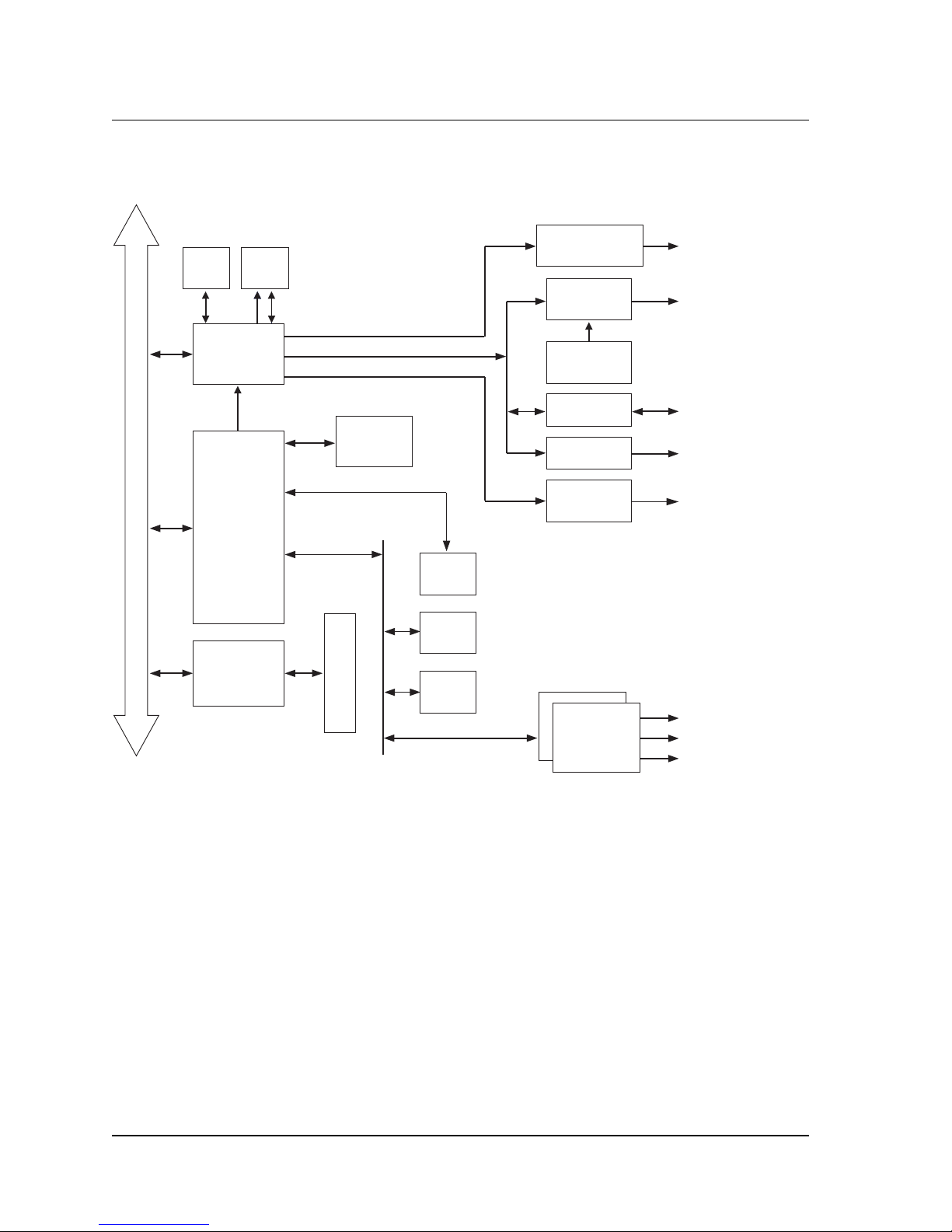
System Flow
The following block diagram shows a typical CineCast HD system flow.
SDRAM
EMBEDDED PCI BUS
HD DECODER
PCI — LOCAL
TRANSPORT
VCX0
TL 850
TL 810 &
DUAL
DEMUX
SCSI
ULTRA 2
ISP1080
MIPS
QED5231a
SCSI CONNECTOR
SDRAM
BOOT
FLASH
FLASH
CCIR-601
YPbPr or RGB
Software Selectable
SDI Video
Audio
Embedder
Transcode
VIP 2.0
Composite
Video
COMPONENT VIDEO
SMPTE 292M VIDEO
VELA MEDIA BRIDGE
VGA DISPLAY
NTSC / PAL VIDEO
AES / ANALOG AUDIO
AUDIO
2 AUDIO PESs
DECODERS
Figure 1-1. CineCast HD Block Diagram
Recommended PC System Configuration
• PC-compatible computer with Pentium 200 or better processor.
• 32MB RAM (64MB recommended).
• PCI bus architecture.
• Microsoft Windows 2000 or Windows NT 4.0 (Service Pack 6a).
• CD-ROM drive for software and driver installation.
System Flow
Page 18

8 CineCast HD Version 2.6 Installation and User Manual
• Ultra-2 / Wide (16-bit) SCSI-3 host adapter (PCI bus), such as those made
by Qlogic™. See“Host Adapter (Initiator) Configuration” on page 12 for
configuration information.
• System hard drive (SCSI, EIDE or IDE) for operating system.
• Dedicated SCSI hard drive to hold MPEG video files.
Decoder Specifications
See Appendix A for a complete list of CineCast HD decoder specifications.
CineCast Playback Application Overview
The full-featured CineCast Playback Application ships with every Vela CineCast
HD decoder. Details of the application, including GUI screen illustrations, playback
mode details, and setup mode information can be found in Chapter 3 of this manual.
Functions Summary
Item Functions/Commands
1. Play
2. Stop
3. Blank Video
4. Un-Blank Video
5. Pause Video (Freeze frame & stop playback)
6. Fast Forward (one speed)
7. Slow Motion (various speeds)
8. Resume Normal Play from Slow, Fast Motion, or Pause
9. Single Step (after Pause)
10. Frame Advance
11. On-Screen Display
12. Back-to-back with no black mode
13. Loop Mode
Table 1-1. CineCast HD Functions Summary
Decoder Specifications
Page 19

Chapter 1 — Getting Started 9
Item Functions/Commands
14. Play List
15. Pause on Under-run Mode
• Freeze video
• Go to black
16. Pause on First Frame of Video
17. Pause on Last Frame of Video
18. Mid-Steam Start
• By Frame Counts
• By SMPTE Time Code
• By Byte Offset
19 Output Resolution Select
20. Audio/Video PID Select
21. Genlock Mode Select:
• Genlock disable (standalone mode)
• Genlock enable
22. A/V Switch and fade
23. Programmable Audio/Video Fade: 0 – 255 frames
24. Audio Attenuation Control
• 18dB/20dB Select (analog)
• Step Attenuation: 1/16 dB/step
25. Audio Output Select
• MPEG Audio
• AC-3 Bitstream Out
• AAC Two Channel
• AAC 5.1 Channel
26. Linear Time Code Output Source Select (Each decode channel)
• MPEG Stream Time Code Extraction
• Frame Count
27. Revision Page
28. Error Reporting On/Off
Table 1-1. CineCast HD Functions Summary
Functions Summary
Page 20

10 CineCast HD Version 2.6 Installation and User Manual
Item Functions/Commands
29. Firmware Download Mode
30. LTC Output Reporting
Table 1-1. CineCast HD Functions Summary
Decoder Installation
HD Board Only Installation
1. Power off the PC, unplug it from the AC source, and remove the cover to
expose the chassis and motherboard.
2. It is important that the CineCast HD decoder board be plugged into a PCI bus
master slot, making sure the edge connectors are fully engaged. Secure the board’s
mounting bracket to the PC chassis.
3. Connect video, audio, genlock, and SCSI cables as required.
4. Set the SCSI ID switch to the correct ID. Set the SCSI terminator switch to the
down position to disable the internal SCSI terminators, if required.
5. Reinstall the PC cover and power up normally.
Models HD/1 and HD/2 Rack-Mount Decoders
1. Install the decoder unit in a suitable 19-inch equipment rack, insuring that
adequate ventilation is available.
2. Connect video, audio, and SCSI cables as required.
3. Set the SCSI ID switch to the correct ID. Set the SCSI terminator switch to the
down position to disable the internal SCSI terminators.
4. Assure that the AC power switch on the front panel is off, then connect the
AC power cable from the receptacle on the rear of the unit to a suitable AC
outlet. Note that if a customer-supplied power cable is used, it must be equal to
or exceed 18 AWG, 1250W, 10A-125V.
5. Power-up the unit by depressing the power switch.
6. The play indicator(s) and the power indicator on the front panel should begin
blinking, indicating normal operation.
Decoder Installation
Page 21

Chapter 1 — Getting Started 11
The SCSI Interface
The Vela CineCast HD decoder connects to the host system through a Small
Computer Systems Interface (SCSI) interface. This interface conforms to the
following ANSI standards, except as detailed in this specification. The type of
interface is Low Voltage Differential Signal (LVDS) Ultra-2 (Fast-40), which is
compatible with single-ended (SE) Ultra (Fast-20) SCSI.
American National Standards Institute SCSI Standards
SCSI-3 Architectural Model (SAM) X.3.270:1996
SCSI-3 Interlocked Protocol (SIP) X.3.292:1997
SCSI-3 Primary Commands (SPC) X.3.301:1997
SCSI-3 Parallel Interface (SPI) X.3.253:1995
SCSI-3 Parallel Interface-2 (SPI-2) X.3.302:1999
SCSI-3 Fast-20 Parallel Interface (Fast-20)X.3.277:1996
SCSI IDs
Typically, each device on a SCSI bus, including the host adapter, must have a
unique SCSI ID. The SCSI ID serves two purposes:
• It uniquely defines each SCSI device on the bus.
• It determines the device’s priority on the bus during arbitration for the bus.
Setting the Decoder’s SCSI ID
The SCSI ID of the CineCast HD decoder is set via the SCSI ID selector switch
located on the rear of the board or on the rear panel of HD/1 and HD/2 models. It
should be noted that ID7 is usually reserved for the SCSI initiator (host adapter).
On HD/2 decoders, a unique ID should be set for each of the two boards
Priority in Arbitrating For the Bus
• Normally, the SCSI initiator (host adapter) is set for SCSI ID 7, which is the
highest priority.
• Each SCSI device on the bus must have a unique SCSI ID.
• Not all host adapters support SCSI IDs 8–15.
• Some host adapters and operating systems have further restrictions on SCSI
IDs for hard disk, CD-ROMs, and tape drives.
• Operating systems and SCSI device drivers may restrict the use of SCSI IDs
to SCSI IDs 0 through 7 only.
Decoder Installation
Page 22

12 CineCast HD Version 2.6 Installation and User Manual
Bus Termination
A terminator switch is located on the rear of the decoder board. Setting the switch
to the left position (farthest away from the connector area) enables termination.
Model HD/2 decoders should have termination enabled on only one of the two
boards contained within the unit, per general SCSI procedures.
Host Adapter (Initiator) Configuration
The following Ultra-2 SCSI host adapters, based on the PCI bus, are recommended:
• Qlogic™ Ultra-2 Wide SCSI host adapter, model QLA-1080.
• Adaptec™ 29160 Ultra 160 host adapter.
Host Adapter Parameter Setting
Disconnect Allowed Enabled (mandatory for multiple SCSI
decoder operation)
Synchronous Data Transfer
(Synchronous Negotiation)
Synchronous Data Transfer Rate 80M transfers/second (REQ/ACK period)
Wide Data Transfer (16-bit) Enabled
Renegotiate on Error Enabled
Enable Device at Boot Enabled
Enable LUN Enabled
Table 1-2. Host Adapter Settings
Parameter Decoder
SCSI Supports SCSI Disconnect-Reconnect
SCSI Transfer Rates
• Asynchronous SCSI supports up to 10MBps for fast/
wide SCSI (16-bit Fast SCSI-2)
• Synchronous SCSI supports 80MBps for Ultra-2/Wide
SCSI (16-bit Ultra-2 SCSI-2)
Enabled
Table 1-3. SCSI Parameters
Decoder Installation
Page 23

Chapter 1 — Getting Started 13
Parameter Decoder
SCSI ID and LUN Provides selectable SCSI ID (0–15)
Termination Selectable termination
Table 1-3. SCSI Parameters
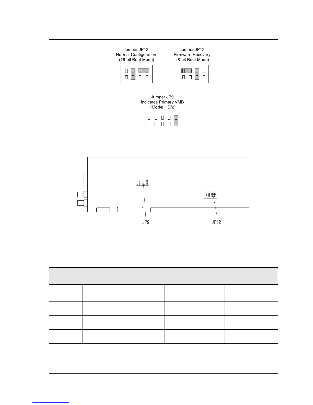
Jumper Information
See Figure 1-22 for jumper locations on the HD circuit board. Most jumpers
should be left in their factory default positions.
In case of a corrupt firmware, situation, Jumper JP6 will need to be reconfigured
from its default 16-bit boot mode to an 8-bit boot mode to enable recovery of
firmware settings. See Figure 1-2 for default and firmware recovery setting.
Jumper JP9 indicates the primary Vela Media Bus decoder board. In board-only
and Model HD/1 versions, the jumper is normally open. In the case of HD/2
models (with two boards), one and only one of the two boards should have this
jumper enabled. See Figure 1-2 for primary VMB jumper placement.
Connector Locations and Pinouts
Refer to Figure 1-22 to locate and identify the various connectors, switches and
jumpers that populate the CineCast HD decoder board. Two BNC connectors
are provided for digital video output and genlock input. Connector P1 is a
Molex brand “Microcross” (P&D) multi-functional connector through which
the decoded signals are output.
CineCast HD Multi-Output Cable Assembly
Figure 1-24 is a representation of an accessory multi-output cable that can be
purchased from Vela to facilitate easy connection of the CineCast HD decoder.
Depending on the cable purchased, signals appearing on the cable can include
YUV, RGB and composite video, LTC time code, AES audio, analog audio, GPI
in and out, and VGA monitor signals.
The input end of the cable assembly terminates in a connector that mates with the
Microcross P&D connector located on the CineCast HD decoder board.
Table 1-4 and Table 1-5 contain pinout information for the available pre-fabricated cable assemblies. Vela part numbers are 6000-0165 (YUV and balanced
audio) and 6000-0166 (RGB and balanced audio). Contact your Vela sales representative to order the cable assemblies.
Connector Locations and Pinouts
Page 24
14 CineCast HD Version 2.6 Installation and User Manual
GENERAL LOCATION OF JUMPERS JP9 AND JP12
(MAGNIFIED VIEW OF JUMPERS)
Figure 1-2. CineCast HD Jumper Settings
Pinouts For YUV Cable (p/n 6000-0165)
Molex Microcross Connector Pinouts (Cable Assy 6000-0165)
P1 Pin No. Signal Destination Cable Type
1 Analog Audio Ch. 1 Right (–) P2, Pin 3 (XLR) Shielded Audio
11 Analog Audio Ch. 1 Right (Gnd) P2, Pin 1 (XLR) Shielded Audio
21 Analog Audio Ch. 1 Right (+) P2, Pin 2 (XLR) Shielded Audio
Table 1-4. Molex Microcross Connector Pinouts, Cable 6000-0165
Connector Locations and Pinouts
Page 25

Chapter 1 — Getting Started 15
Molex Microcross Connector Pinouts (Cable Assy 6000-0165) (Continued)
P1 Pin No. Signal Destination Cable Type
2 Analog Audio Ch. 1 Left (–) P3, Pin 3 (XLR) Shielded Audio
12 Analog Audio Ch. 1 Left (Gnd) P3, Pin 1 (XLR) Shielded Audio
22 Analog Audio Ch. 1 Left (+) P3, Pin 2 (XLR) Shielded Audio
3 Analog Audio Ch. 2 Right (–) P4, Pin 3 (XLR) Shielded Audio
13 Analog Audio Ch. 2 Right (Gnd) P4, Pin 1 (XLR) Shielded Audio
23 Analog Audio Ch. 2 Right (+) P4, Pin 2 (XLR) Shielded Audio
4 Analog Audio Ch. 2 Left (–) P5, Pin 3 (XLR) Shielded Audio
14 Analog Audio Ch. 2 Left (Gnd) P5, Pin 1 (XLR) Shielded Audio
24 Analog Audio Ch. 2 Left (+) P5, Pin 2 (XLR) Shielded Audio
6 AES Audio Ch. A P6, Center Conductor 75-Ohm Coax
5 AES Audio Ch. A P6, Shield 75-Ohm Coax
16 AES Audio Ch. B P7, Center Conductor 75-Ohm Coax
15 AES Audio Ch. B P7, Shield 75-Ohm Coax
26 AES Audio Ch. C P8, Center Conductor 75-Ohm Coax
25 AES Audio Ch. C P8, Shield 75-Ohm Coax
27 LTC Out (–) P9, Pin 3 (XLR) Shielded Audio
17 LTC Out (Gnd) P9, Pin 1 (XLR) Shielded Audio
7 LTC Out (+) P9, Pin 2 (XLR) Shielded Audio
8 GPI Out P10 Pigtail Lead
Table 1-4. Molex Microcross Connector Pinouts, Cable 6000-0165 (Continued)
Connector Locations and Pinouts
Page 26

16 CineCast HD Version 2.6 Installation and User Manual
Molex Microcross Connector Pinouts (Cable Assy 6000-0165) (Continued)
P1 Pin No. Signal Destination Cable Type
28 GPI In P10 Pigtail Lead
9 Not Used Not Used Twisted Pair Cable
10 Not Used Not Used Twisted Pair Cable
18 Not Used Not Used Not Used
C3 HSync Signal P11, Center Conductor 75-Ohm Coax
C5 HSync Signal P11, Shield 75-Ohm Coax
C4 Green/Y Signal P12, Center Conductor 75-Ohm Coax
C5 Green/Y Signal P12, Shield 75-Ohm Coax
C1 Red/PR Signal P13, Center Conductor 75-Ohm Coax
C5 Red/PR Signal P13, Shield 75-Ohm Coax
C2 Blue/PR Signal P14, Center Conductor 75-Ohm Coax
C5 Blue/PR Signal P14, Shield 75-Ohm Coax
30 VSync Signal P15, Center Conductor 75-Ohm Coax
20 VSync Signal P15, Shield 75-Ohm Coax
29 Composite Video P16, Center Conductor 75-Ohm Coax
19 Composite Video P16, Shield 75-Ohm Coax
Table 1-4. Molex Microcross Connector Pinouts, Cable 6000-0165 (Continued)
Connector Locations and Pinouts
Page 27

Chapter 1 — Getting Started 17
Pinouts For RGB Cable (p/n 6000-0166)
Molex Microcross Connector Pinouts (Cable Assy 6000-0166)
P1 Pin No. Signal Destination Cable Type
1 Analog Audio Ch. 1 Right (–) P2, Pin 3 (XLR) Shielded Audio
11 Analog Audio Ch. 1 Right (Gnd) P2, Pin 1 (XLR) Shielded Audio
21 Analog Audio Ch. 1 Right (+) P2, Pin 2 (XLR) Shielded Audio
2 Analog Audio Ch. 1 Left (–) P3, Pin 3 (XLR) Shielded Audio
12 Analog Audio Ch. 1 Left (Gnd) P3, Pin 1 (XLR) Shielded Audio
22 Analog Audio Ch. 1 Left (+) P3, Pin 2 (XLR) Shielded Audio
3 Analog Audio Ch. 2 Right (–) P4, Pin 3 (XLR) Shielded Audio
13 Analog Audio Ch. 2 Right (Gnd) P4, Pin 1 (XLR) Shielded Audio
23 Analog Audio Ch. 2 Right (+) P4, Pin 2 (XLR) Shielded Audio
4 Analog Audio Ch. 2 Left (–) P5, Pin 3 (XLR) Shielded Audio
14 Analog Audio Ch. 2 Left (Gnd) P5, Pin 1 (XLR) Shielded Audio
24 Analog Audio Ch. 2 Left (+) P5, Pin 2 (XLR) Shielded Audio
6 AES Audio Ch. A P6, Center Conductor 75-Ohm Coax
5 AES Audio Ch. A P6, Shield 75-Ohm Coax
16 AES Audio Ch. B P7, Center Conductor 75-Ohm Coax
15 AES Audio Ch. B P7, Shield 75-Ohm Coax
26 AES Audio Ch. C P8, Center Conductor 75-Ohm Coax
25 AES Audio Ch. C P8, Shield 75-Ohm Coax
27 LTC Out (–) P9, Pin 3 (XLR) Shielded Audio
Table 1-5. Molex Microcross Connector Pinouts, Cable 6000-0166
Connector Locations and Pinouts
Page 28

18 CineCast HD Version 2.6 Installation and User Manual
Molex Microcross Connector Pinouts (Cable Assy 6000-0166) (Continued)
P1 Pin No. Signal Destination Cable Type
17 LTC Out (Gnd) P9, Pin 1 (XLR) Shielded Audio
7 LTC Out (+) P9, Pin 2 (XLR) Shielded Audio
8 GPI Out P10 Pigtail Lead
28 GPI In P10 Pigtail Lead
9 Not Used P11, Pin 15 Twisted Pair Cable
10 Not Used P11, Pin 12 Twisted Pair Cable
18 Not Used Not Used Not Used
C3 HSync Signal P11, Pin 1 75-Ohm Coax
C5 HSync Signal P11, Pin 5 75-Ohm Coax
C4 VGA Signal P11, Pin 2 75-Ohm Coax
C5 VGA Signal P11, Pin 6 75-Ohm Coax
C1 Red/PR Signal P11, Pin 3 75-Ohm Coax
C5 Red/PR Signal P11, Pin 10 75-Ohm Coax
C2 Blue/PR Signal P11, Pin 13 75-Ohm Coax
C5 Blue/PR Signal P11, Pin 7 75-Ohm Coax
30 VSync Signal P11, Pin 14 75-Ohm Coax
20 VSync Signal P11, Pin 8 75-Ohm Coax
29 Composite Video P12, Center Conductor 75-Ohm Coax
19 Composite Video P12, Shield 75-Ohm Coax
Table 1-5. Molex Microcross Connector Pinouts, Cable 6000-0166 (Continued)
Connector Locations and Pinouts
Page 29

Chapter 1 — Getting Started 19
Software Installation
The following sections pertain to the installation of Vela Release 2.6 system software for the CineCast HD decoder. Determine the operating system you are using
(Windows 2000 or Windows NT) and follow the corresponding instructions.
Be sure to review the “readme” files on the system software CD-ROM for
the very latest information on installation and performance issues.
Installing Under Windows NT
All of the software that you need to install the CineCast HD decoder on Windows
NT 4.0 is located on the single CD-ROM you received with the decoder. Just
follow these steps, whether you are upgrading to version 2.6 or installing it for the
first time. Remember that a number of system restarts (reboots) may be required
during the installation process. Do not remove the CD-ROM disc from the
drive until you've completed the last step of the installation process.
NOTE: Hardware drivers for Windows NT are automatically installed with the application.
1. Uninstall any CineCast software currently on the system. Use the Windows
Control Panel > Add/Remove Programs application. For compete details
on uninstalling current and previous versions of software, see “Uninstalling CineCast Software” on page 36.
2. Install Windows NT Service Pack 6a or later, if it’s not already installed on
your system. You can download this service pack from the Internet, or you can
install it from the CineCast System Software CD-ROM, as follows:
• Insert the CD-ROM into the CD-ROM Drive. The Autorun install setup
screen will appear (Figure 1-3).
• From the Autorun screen, select the “Explore This CD” option. A screen
similar to that in Figure 1-4 will appear.
• Double-click on the System folder, then double-click on the “NT Service
Pack” folder.
• Double-click on the sp6i386.exe file.
• The application will extract files, then ask you to read a license agreement.
After reading the agreement, check the “Accept License Agreement”
checkbox as well as the “Backup Files Required to Uninstall” checkbox.
• Click Install.
• Click Next, OK, or Finished to all of the screens that follow.
Software Installation
Page 30

20 CineCast HD Version 2.6 Installation and User Manual
• If you are asked to reboot, allow the system to restart before continuing.
3. The Autorun setup screen (Figure 1-3) should appear after the reboot. If it
does not, use Windows Explorer to select and run setup.exe from the CD-ROM.
4. Install Internet Explorer version 5, Service Pack 4 or later, if it's not already
installed on your system. Again, you can download this from the Internet, or
you can install it from the Vela system software installation CD-ROM. To use
the CD-ROM, follow these steps:
• Insert the CD-ROM disc into the CD-ROM drive.
• When the setup screen appears, select the “Explore This CD” option.
• Double-click on the “System” folder.
• Double-click on the “MSIE5 NT” folder.
• Double-click on the setup.exe icon. When a window pops up to select
“Typical” or “Minimal” Installation, select “Minimal.”
• On the next screen, deselect (remove the checks from) the “Windows Media
Player” and “Outlook Express” selections.
• The version of Windows Media Player included with Internet Explorer 5.0 is
outdated. A more recent version is included on this CD, though the installation of Windows Media Player and Outlook Express are not a requirement
for the CineCast HD decoder.
• Click Next, OK, or Finished to all of the screens that follow.
• If you are asked to reboot, allow the system to restart before continuing.
5. The setup screen should appear after the reboot. If it does not, use Windows
Explorer to select and run setup.exe from the CD-ROM or click Start > Run.
6. Install MDAC 2.6, if it is not already installed on your system. Again, you
can download this from the Internet, or you can install it from the installation
CD-ROM. To use the CD-ROM, follow these steps:
• Insert the CD-ROM into the CD-ROM drive.
• When the setup screen appears, select the “Explore This CD” option.
• Double-click on the “System” folder.
• Double-click on the “MDAC 2.6" folder.
• Double-click on the mdac_typ.exe.
• The application will extract files, then ask you to read a license agreement.
Software Installation
Page 31

Chapter 1 — Getting Started 21
After reading the agreement, check the “Accept License Agreement”
checkbox. Click Next.
• If you are asked to restart, allow the system to reboot before continuing.
7. The Autorun setup screen (Figure 1-3) should appear after the system
restart. If it does not, use Windows Explorer to select and run setup.exe from
the CD-ROM or click Start > Run.
8. From the Autorun setup screen, select Install “CineCast,” then follow the
steps listed below:
• Read the Welcome screen (Figure 1-5), then click Next.
• On the “Choose Destination Location” screen (Figure 1-6), accept the
Program Files\ Vela Research
destination, as listed, by clicking Next.
Do not change the destination! The default destination is required
for proper decoder operation.
9. On the “Select Components” screen (Figure 1-7):
• If you have not yet run the MFC update option for this release, check the
“MFC Update” checkbox on the “Select Components” screen. This step
needs to be done only once. If you check this box, there will be an extra set
of steps automatically included in the procedure specified below— and the
installation procedure will require an additional system restart. Just follow
the instructions presented by the MFCupdate.exe installation application.
• Also check the “CineCast Decoder Application” checkbox.
• If you have purchased the SDK, check the “CineCast Decoder SDK” check
box, too. (Because it is password-protected, you will be able to install the
SDK only if you purchased it and received the corresponding password.
If you cannot locate the password, call Vela Support for assistance. You can
return to this screen to install the SDK at a later time if you need to).
C:\
• Reminder: If you have not already done so, you must enable “MFC Update”
and “CineCast Decoder Application.” These two checkboxes must be
checked when requesting the SDK to insure proper installation of the SDK.
• Click Next to proceed with the installation.
• On the “Select Program Manager Group” screen (Figure 1-8), accept Vela
Research by clicking Next.
• On the “Start Installation” screen (Figure 1-9), click Next.
Software Installation
Page 32

22 CineCast HD Version 2.6 Installation and User Manual
• A “DO NOT REMOVE THE CD” message box will display as a reminder
that a number of reboots may be required during the installation process.
Click OK to continue.
• If you have chosen to run the MFC Update option, the installation process
will begin here to copy files.
• On the “Install” message box (Figure 1-10), note that the system must
be restarted. Click OK, and then wait as the system reboots. Leave the
CD-ROM in the drive through the system restart process.
10. If you remembered to leave the CD-ROM in the drive, the setup application
will appear soon after the reboot. Continue the installation by following these steps:
• On the “CineCast License Agreement” screen (Figure 1-11), select the “I
Agree” radio button after reading the agreement. Then click OK. The
application will install some files.
11. If you elected to install the SDK:
• Select the “I Agree” radio button on the “CineCast SDK End User
License Agreement” screen (Figure 1-12). Click OK.
• On the Password screen (Figure 1-13), you will be asked for a password. Use
the one supplied when you purchased your Software Developer’s Kit. If you
have problems finding your password, contact Vela Support. After entering
the password, click OK. A few more files will be installed.
12. On the “Installation Complete” screen (Figure 1-14), note that CineCast 2.6
has been successfully installed. Click Finish.
13. The “Install” message box (Figure 1-10) will note that the system must be restarted. Click OK, then let the system reboot. Leave the CD-ROM in the drive.
14. After the system has been rebooted, close the setup application if it is active,
then remove the CD-ROM disc from the drive.
Software Installation
Page 33

Chapter 1 — Getting Started 23
Figure 1-3. Installation Autorun Setup Screen
Figure 1-4. “Explore This CD” Screen
Software Installation
Page 34

24 CineCast HD Version 2.6 Installation and User Manual
Figure 1-5. Install Welcome Screen
Figure 1-6. Destination Location Screen
Software Installation
Page 35

Chapter 1 — Getting Started 25
Figure 1-7. Select Components Screen
Figure 1-8. Program Manager Group Screen
Software Installation
Page 36

26 CineCast HD Version 2.6 Installation and User Manual
Figure 1-9. Installation Start Screen
Figure 1-10. Install Restart Message
Software Installation
Page 37

Chapter 1 — Getting Started 27
Figure 1-11. CineCast License Agreement Screen
Figure 1-12. CineCast SDK License Agreement Screen
Software Installation
Page 38

28 CineCast HD Version 2.6 Installation and User Manual
Figure 1-13. Password Dialog Box
Figure 1-14. Installation Completion Screen
Software Installation
Page 39

Chapter 1 — Getting Started 29
Installing Under Windows 2000
Just follow these steps to upgrade to version 2.6, remembering that a number of
reboots may be required during the installation process. Do not remove the
CD-ROM disc from the drive until you've completed the final step.
Note: Do not install any new hardware at this time.
If CineCast decoder system software is currently installed, first uninstall the software from the Control Panel. See “Uninstalling CineCast Software” on page 36.
1. Install Windows 2000 Service Pack 2, if it is not already installed on your
system. You can download this service pack from the Internet, or you can install
it from the CD-ROM. To use the CD-ROM, follow these steps:
• From the Autorun screen (Figure 1-3), select “Explore This CD.”
• From the “Explore This CD” screen (Figure 1-4), double-click on the
System folder.
• Double-click on the “Win2k Service Pack” folder.
• Double-click on the w2ksp2.exe file.
• The application will extract files, then ask you to read a license agreement.
After reading the agreement, check the “Accept License Agreement” checkbox as well as the “Backup Files Required to Uninstall” checkbox.
• Click Install.
• Click Next, OK, or Finished to all of the screens that follow.
• If you are asked to reboot, allow the system to restart before continuing.
2. The Autorun screen should appear after the reboot. If it does not, run
setup.exe from the CD-ROM or click Start > Run.
After installing Windows 2000 Service Pack 2, if necessary, follow the instructions below to install hardware drivers. after installing any Vela hardware.
Remember that a number of reboots may be required during the install process.
Hardware Driver Installation — Windows 2000
Before installing CineCast release 2.6 system software, and after installing the
Windows 2000 Service Pack 2, follow these directions to install the hardware
drivers:
1. Shut down Windows, power off the system, and install the new hardware.
2. After reassembling the machine, power up any external decoders, such as the
CineCast HD/1 or HD/2 rack-mount decoders, then power up the host PC.
3. If the “Add New Hardware Wizard” appears, click Cancel.
Software Installation
Page 40

30 CineCast HD Version 2.6 Installation and User Manual
4. If the “Digital Signature Not Found” screen appears, click Yes to continue
with the installation.
5. Insert the CD-ROM if you have not already done so. Exit the Autorun setup
screen if it appears.
6. Right click on the “My Computer” icon on the desktop. A drop-down menu
should appear. Highlight “Properties,” then click on it.
7. Click on the tab labeled “Hardware.”
8. Click on “Device Manager.” A screen similar to that of Figure 1-15 appears.
Click on the Action tab, then “Scan for hardware changes.”
9. The “Found New Hardware Wizard” will detect the Vela CineCast decoder
type. The “Device Driver Wizard” screen will appear (Figure 1-16). Click Next.
10. Wizard screen “Install Hardware Device Drivers” (Figure 1-17) appears.
Select the radio button “Search for a suitable driver for my device.” Click Next.
11. Wizard screen “Locate Driver Files” (Figure 1-18) will appear. Check
“Specify a Location,” then click Next.
12. A message box (Figure 1-19) will appear that will allow you to browse your
computer until you find a driver for the Multimedia controller. Check Browse to
select the device from the following path for the driver.
Drivers\Cinecast\Windows 2000\Cinecast.INF.
Note: When prompted for the CineCast.sys file, the directory path is the same as above.
13. When the Vela Decoder driver installation is complete, a prompt screen
(Figure 1-20) will appear: “Completing the Upgrade Device Driver Wizard.” Click
Finish. Close the screens and return to “Device Manager,” where the Vela CineCast
decoder should be recognized. Repeat steps 9–14 for each device as needed.
14. When the Vela CineCast driver installation is complete, a prompt screen
(Figure 1-20) will appear: “Completing the Upgrade Device Driver Wizard.”
Click Finish. Close screens and return to “Device Manager,” where each Vela CineCast decoder should be recognized,
15. At this time you will receive a “System Settings Change” message box (Figure
1-21). Click Yes to restart the system. If this does not occur, manually reboot your
system. Do not remove the CD-ROM disc during the restart process.
16. The setup screen should pop up after the system restart. If it does not, run
setup.exe from the CD-ROM or click Start > Run.
Proceed with the installation of CineCast system software. See “Installing CineCast 2.6 Software (Windows 2000)” on page 34.
Software Installation
Page 41

Chapter 1 — Getting Started 31
Figure 1-15. System Properties Device Manager Screen
Figure 1-16. Device Driver Wizard: Welcome Screen
Software Installation
Page 42

32 CineCast HD Version 2.6 Installation and User Manual
Figure 1-17. Device Driver Wizard: Install Drivers
Figure 1-18. Device Driver Wizard: Locate Driver Files
Software Installation
Page 43

Chapter 1 — Getting Started 33
Figure 1-19. Device Driver Wizard: Browse Window
Figure 1-20. Device Driver Wizard: Completion
Software Installation
Page 44

34 CineCast HD Version 2.6 Installation and User Manual
Figure 1-21. System Settings Change Message Box
Installing CineCast 2.6 Software (Windows 2000)
1. Install MDAC 2.6, if it is not already installed on your system. Again you
can download this from the Internet, or you can install it from the installation
CD-ROM. To use the CD-ROM, follow these steps:
• Insert the CD-ROM into the CD-ROM drive.
• When the Autorun setup screen (Figure 1-3) appears, select the “Explore
This CD” option (Figure 1-4).
• Double-click on the “System” folder.
• Double-click on the “MDAC 2.6" folder.
• Double-click on the mdac_typ.exe.
• The application will extract files, then ask you to read a license agreement.
After reading the agreement, check the “Accept License Agreement”
checkbox. Click Next.
• If you are asked to restart, allow the system to reboot before continuing.
2. The Autorun setup screen (Figure 1-3) should appear after the system restart.
If it does not, use Windows Explorer to select and run setup.exe from the CDROM or click Start > Run.
3. From the Autorun setup screen, select Install “CineCast,” then follow the
steps listed below:
• Read the Welcome screen (Figure 1-5), then click Next.
• On the “Choose Destination Location” screen (Figure 1-6), accept the
C:\ Program Files\ Vela Research destination, as listed, by clicking Next.
Do not change the destination! The default destination is required for
proper decoder operation.
4. On the “Select Components” screen (Figure 1-7):
Software Installation
Page 45

Chapter 1 — Getting Started 35
• If you have not yet run the MFC update option for this release, check the
“MFC Update” checkbox on the “Select Components” screen. This step
needs to be done only once. If you check this box, there will be an extra set
of steps automatically included in the procedure specified below— and the
installation procedure will require an additional system restart. Just follow
the instructions presented by the MFCupdate.exe installation application.
• Under Required Components on the “Select Components” screen, check the
“Core Decoder Modules” checkbox.
• Click Next to proceed with the installation of the selected components.
• On the “Select Program Manager Group” screen (Figure 1-8), accept Vela
Research by clicking Next.
• On the “Start Installation” screen (Figure 1-9), click Next.
• A “DO NOT REMOVE THE CD” message box will display as a reminder
that a number of reboots may be required during the installation process.
Click OK to continue.
• If you have chosen to run the MFC Update option, the installation process
will begin here to copy files. Note: If you have not already done so, you
must run the “MFC Update” and “Core Decoder Modules” under Required
Components. These two check-boxes must always be checked when requesting the SDK — This insures proper installation of the SDK.
• On the “Install” message box (Figure 1-10), note that the system must be
restarted. Click OK, and then wait as the system reboots. Leave the CD-
ROM in the drive through the system restart process.
5. If you remembered to leave the CD-ROM in the drive, the setup application
pops up immediately after the reboot. Continue with the installation by following
these steps:
• On the “CineCast End User License Agreement” screen (Figure 1-11), select
the “I Agree” radio button after reading the agreement. Then click OK.
The application will install some files.
6. If you elected to install the SDK:
• Select the “I Agree” radio button on the “CineCast SDK End User License
Agreement” screen (Figure 1-12). Click OK.
• On the Password screen (Figure 1-13), you will be asked for a password. Use
the one supplied when you purchased your Software Developer’s Kit. If you
have problems finding your password, contact Vela Support. After entering
the password, click OK. A few more files will be installed.
Software Installation
Page 46

36 CineCast HD Version 2.6 Installation and User Manual
7. On the “Installation Complete” screen (Figure 1-14), note that CineCast 2.6
has been successfully installed. Click Finish.
8. The “Install” message box (Figure 1-10) will note that the system must be restarted. Click OK, then let the system reboot. Leave the CD-ROM in the drive.
9. After the system has been rebooted, close the setup application if it is active,
then remove the CD-ROM from the drive.
Uninstalling CineCast Software
If, at some point, you need to uninstall CineCast decoder system software,
always use the Windows Control Panel > Add/Remove Programs application.
Never manually remove any files installed by the installation process, unless
specifically directed, as doing so may prevent proper removal of some or all of
the files installed. Note that complete removal of the product with Add/Remove
Programs is possible only if the product was originally installed in the default
target folder created by the install process.
In most cases, when you upgrade to version 2.6, you'll be removing a previous
version of CineCast software. To uninstall that previous version of software, consult the user's manual that you received when you installed it. At some point, you
may need to uninstall CineCast version 2.6 from your system. To do so, just
follow the steps below.
• On the software list that is displayed when you select “Add/Remove
Programs” from the Control Panel, click on the entry that begins with
the phrase “Vela Research, Software Version ….” Then, on the Uninstall
Information panel, click OK.
• When asked to select the uninstall method, select “Automatic” and click Next.
• You may see a message indicating that a particular file is no longer being
used by any program. Click “Yes to All” to delete it and any other such files.
• On other screens that may appear, Click on Next or Finish until the uninstall process is complete.
• After you click Finish on the last screen of the uninstall procedure, you will
be asked to restart the system. Click OK, and allow the system to restart.
When the system has finished rebooting, there should be no file entries in the
C:\Program Files\Vela Research folder. If you find files or folders remaining
in the
C:\Program Files\Vela Research folder, delete them manually.
Software Installation
Page 47

Chapter 1 — Getting Started 37
Application Development
Vela offers a Windows-based SCSI Software Developer’s Kit (SDK) which
includes dynamic linked libraries (DLLs) and documentation of function calls,
permitting programmers to design specialized functionality for the CineCast
HD decoder. The Vela CineCast SCSI SDK includes the following:
• SCSI Application Programming Interface (API) source documentation of
function calls.
• Sample applications for Visual C++ 6.0 and Visual Basic 6.0.
• Sample application source code examples.
Contact Vela for pricing and availability of the CineCast SDK. Vela’s Customer
Service number is (727) 507-5301. You may also contact the Vela representative
serving your geographic region to obtain the SDK. Note that installation of the
SDK is a password-protected process. Included with the SDK is a authenticated
password that allows installation of the SDK and accompanying files.
Along with the optional SDK, the setup program installs Microsoft Visual Basic™
and Microsoft Visual C++™ sample applications that can be used to decode and
play MPEG encoded files through the CineCast Prime. The SDK requires versions
6.0 or higher of Visual Basic and Visual C++.
Customer Support
In the event of problems with your CineCast HD decoder, do not hesitate to contact Vela Training and Support using the following methods:
• Phone: (727) 507-5301
• E-mail: support@vela.com
• World Wide Web — http://www.vela.com
Application Development
Page 48

38 CineCast HD Version 2.6 Installation and User Manual
Figure 1-22.CineCast HD Decoder Chassis Layout
Customer Support
Page 49

Chapter 1 — Getting Started 39
Figure 1-23.CineCast HD Rear Panel View
Customer Support
Page 50

40 CineCast HD Version 2.6 Installation and User Manual
Figure 1-24.CineCast HD Cable Assembly, P/N 6000-0165
Customer Support
Page 51

Chapter 1 — Getting Started 41
Figure 1-25.CineCast HD Cable Assembly, P/N 6000-0166
Customer Support
Page 52

Page 53

Chapter 2
Decoder Command Set Guide
SCSI Decoder Command Set
This command set for the Vela CineCast HD decoder family performs per the
SCSI-2 Standard. Contact Vela for the latest firmware revision and complete
information on the command set, if needed.
SCSI Command Sequence from Power-up, SCSI
Reset, or Bus Device Reset
The CineCast HD decoder will report Check Condition to the first SCSI command (excluding
seeing the check condition, should respond by performing a
Per SCSI recommendations, the initiator should renegotiate for synchronous data
transfers and wide transfers. This is done to enable hot swap capability and proper
negotiation for Sync and Wide data.
INQUIRY and REQUEST SENSE). The host adapter (initiator), after
REQUEST SENSE.
SCSI Command Name Operation Code SCSI-2 Section Number
Inquiry 12h 8.2.5
Mode Sense 1Ah 8.2.10
Decoder Command 45h Custom Command
MPEG Play A5h Custom Command
Read Capacity 25h 9.2.7
Request Sense 03h 8.2.14
Test Unit Ready 00h 8.2.16
MPEG Write (10) 2Ah 9.2.21
Write Buffer 3Bh 8.2.17
Table 2-1. Command and Status Processing List
The decoder will report Check Condition for all commands except
REQUEST SENSE from a Power-up, SCSI Reset, or Bus Device Reset.
INQUIRY and
Page 54

44 CineCast HD Version 2.6 Installation and User Manual
To enable all commands, the following sequence must be performed:
INQUIRY
TEST
UNIT READY (Will report check condition)
REQUEST SENSE
TEST
UNIT READY (Optional, will report Good status)
This command sequence is typically performed automatically by the SCSI host
adapter (initiator) during power-up. Following the above sequence, all decoder
commands will be active.
SCSI Command Description
The following command descriptions contain detailed information on the SCSI
commands that are supported by the CineCast HD decoder.
Command fields within SCSI Command Descriptor Blocks are supported as
follows:
Logical Unit Number (LUN)
Ignored by the decoder. Per SCSI-2 recommendations this field should be set to
0. This field was used for SCSI-1 devices, but is now reserved. SCSI-2 requires
Logical Unit Number to be specified in the Identify message, not in this field.
Reserved
Reserved bits, fields, bytes, and code values are set aside for future standardization and must be set to zero. If the decoder receives a command that contains
non-zero bits in a reserved field or a reversed code value, the command is terminated with a Check Condition status. The sense key (read via a
is set to
ILLEGAL REQUEST.
REQUEST SENSE)
Control
The control byte is the ending byte of all SCSI Command Descriptor Blocks and
has the following format:
Bit
Byte
0
765
43210
Reserved Flag LinkVendor Specific
Table 2-2. Control Byte Format
NOTE: The control byte of each SCSI command must be zero. Linked commands are
not supported by the decoder.
Page 55

Chapter 2 — Decoder Command Set Guide 45
INQUIRY Command
(OpCode 0x12, 6 bytes)
The INQUIRY command allows the initiator (host adapter) to determine the kind of
SCSI devices attached to its SCSI Bus. It causes a device that is attached to a
SCSI bus to return information about itself. Since the function of the SCSI decoder does not fit into any of the standard SCSI device types, a new device type has
been defined. The function of the MPEG decoder is similar to a Direct Access
Storage Device, e.g., a hard disk, but also has characteristics of a CD-ROM. The
MPEG decoder can be viewed as a write-only device.
The decoder can provide two categories of data in response to an
INQUIRY com-
mand: Standard Inquiry Data and Vital Product Data. Standard Inquiry Data
contains basic data about the decoder, and Vital Product Data comprise several
pages of additional data. Each Vital Product Data page requires a separate
INQUIRY command from the initiator.
Table 2-3. INQUIRY Command Descriptor Block
EVPD
Enable Vital Product Data. If 0, the decoder returns the Standard Inquiry Data
page; if 1, the decoder returns the Vital Product page specified in Page Code.
Page Code
Specifies the Vital Product Data page to be returned.
Allocated Length
Specifies the number of bytes of inquiry
information to be returned to the initiator.
INQUIRY Command
Page 56

46 CineCast HD Version 2.6 Installation and User Manual
Standard Inquiry Data
This is returned when EVPD = 0 with a Page Code = 0. If Page Code is not
zero with EVPD = 0, a Check Condition status is returned. Size of the Standard
Inquiry data is 56 bytes.
Table 2-4. Standard Inquiry Data Block Format
Standard Inquiry Data
Page 57

Chapter 2 — Decoder Command Set Guide 47
Standard Inquiry Data Description
Peripheral Qualifier 0
Peripheral Device Type 0Ch (MPEG SCSI Decoder)
RMB 0
Device-Type Modifier 0
ISO Version 0
ECMA Version 0
ANSI-Approved Version 2 (SCSI-2)
AENC 0 (Asynchronous Event Notification not implemented)
TrmIOP 0 (Terminate I/O Process not supported)
Response Data Format 2 (SCSI-2 data format)
RelAdr 0 (Relative Address not supported)
WBus32 0
WBus16 1 (16-Bit SCSI)
Sync 1 (Synchronous Data Transfers)
Linked 0 (Linked commands not supported)
CmdQue 0 (Command Tag Queing not supported)
SftRe 0 (Hard Reset option of SCSI-2 implemented)
Vendor Identification “Vela” in ASCII (bytes 8-15)
Product Identification “CineCast HD” in ASCII (bytes 16-31)
Product Revision Numerical revision in ASCII (bytes 32-35)
Unit Serial Number “Unknown” in ASCII (bytes 36-51)
Reserved Bytes 52-55
Standard Inquiry Data
Page 58

48 CineCast HD Version 2.6 Installation and User Manual
Vital Product Data Pages
Vital Product Data pages are supported for obtaining additional information about
the decoder. The Vela HD decoder supports the following Vital Product Data pages:
Page Code Vital Product Data
00h Supported Vital Product Data Pages
80h Unit serial number page
C0h Revision page
Supported Vital Product Data Page (00h)
This page lists the Vital Product Data pages supported by the HD. The size of the
Supported Vital product Data page is eight bytes.
Bit
Byte
0
1
2
3
4-6
765
43210
Peripheral Qualifier = 0 Peripheral Device Type = 0Ch
Page Code (00h)
Reserved
Page Length = 4
Support Page List:
00h Supported vital product data pages
80h Unit serial number page
C0h Revision page
7
Table 2-5. Vital Product Data Page Format
Reserved
Unit Serial Number Page (80h)
This page returns the serial number of the decoder. The size of the Unit Serial
Number page is 20 bytes, and currently reports the serial number as “unknown”
in ASCII.
Vital Product Data Pages
Page 59

Chapter 2 — Decoder Command Set Guide 49
Bit
Byte
0
1
2
3
4-19
765
43210
Peripheral Qualifier = 0 Peripheral Device Type = 0Ch
Page Code (80h)
Reserved
Page Length = 16
Unit Serial Number in ASCII
Table 2-6. Unit Serial Number Page Format
Revision Page (C0h)
This page returns the various revision codes of hardware and firmware (microcode) components which make up the CineCast HD decoder.
NOTE: All fields in bytes 4-43 are ASCII characters
Table 2-7. Revision Page Format
Vital Product Data Pages
Page 60

50 CineCast HD Version 2.6 Installation and User Manual
Decoder Firmware Revision
Returns revision of decoder firmware, which is the same as that reported in the
product revision field of the Standard Inquiry data.
Programmable Logic (PLD) Revision
Returns revision of the programmable logic.
FPGA Revision
Returns revision of the FPGA.
SCSI Controller Hardware Revision:
Returns the hardware revision of the SCSI controller. Current revision is “117."
SCSI Controller Firmware Revision
Returns the firmware revision of the SCSI controller. Current revision is “0910.”
TL850 Revision
Returns revision of the MPEG decoding hardware.
Firmware Build Date
Returns eight ASCII characters reflecting the build date of the firmware, e.g.,
“01/10/98”.
MPEG PLAY Command
(OpCode 0xA5, 12 bytes)
This is an OpCode taken from the CDROM PLAY AUDIO (12) command which is
used to start decoder playback. This command is the primary mechanism for
controlling decoder playback.
The power-up default video resolution is the last selected resolution. To change
resolutions, decoder (45h) command with command code 001Bh must be used.
MPEG PLAY Command
Page 61

Chapter 2 — Decoder Command Set Guide 51
Table 2-8. MPEG PLAY Command Format
Error Recovery on Data Under Flow (ErrRcvy)
Determines how the decoder handles a data starvation condition. When set to
zero (default), and when the decoder uses up all data in the DRAM buffer, the
decoder will end playback and force the screen to black. This happens when the
host is not sending data fast enough to keep up with the playback rate. This is a
fatal playback error, in which the decoder is informing the host system that playback has stopped. The decoder will return the following on the next
WRITE (10):
SCSI Status Check Condition
Sense Key 03h Medium Error
Additional Sense Code and Qualifier 0005h End-of-Data Detected
RESET BUFFER command, new data [via WRITE (10)], and a new MPEG PLAY
A
command are required before playback can start again.
When set to 1, the decoder will automatically enter a Pause state when the
MPEG PLAY Command
Page 62

52 CineCast HD Version 2.6 Installation and User Manual
decoder detects that the DRAM buffer is empty. The decoder will wait for eight
64-K buffers to be filled before resuming playback. This mode requires that a
RESET BUFFER be sent at the end of a stream, so the decoder knows the differ-
ence between the data underflow and the end of a stream. Also, the decoder
keeps a count of the number of times this data underrun condition occurs.
Refer to Mode Page (30h).
Mid-Stream Start (Midstrm)
By setting this bit to 1, the decoder will automatically find the first valid sequence
header before starting playback. This allows the start of playback in a random
position within an MPEG file. (This feature may delay video start-up by a few
frames. The end result will be more black between back-to-back videos.)
Autodetect must be used with mid-stream starts. By setting this bit to 0, the
decoder assumes that the MPEG stream begins on a valid sequence header.
Automatic Pause on First Visible Frame (Pause)
When this bit is set to 1, the decoder begins playback, but automatically pauses
on the first non-black video frame. This depends on the value of Pre-Black. Once
paused, use the
pause. Alternatively, the
DECODER (45H) command with code 0012h to resume from
FRAME ADVANCE (010F) command can be used to
advance one video frame.
Trigge r
When this bit is set to 1, the decoder waits for the trigger event (as defined in Trigger
Event) to occur before beginning playback.
Stream Type Hex Code
Autodetect 00h
MPEG-2 Transport Stream 28h
NOTE: All other stream type codes are reserved.
Autodetect
If the stream type is set to 00h, the decoder will parse the beginning of the stream
to determine stream type. The CineCast HD decoder currently only supports
MPEG-2 Transport streams.
Pre-Black
8-bit pre-black interval in video frames. A value of 0h uses default pre-black (first
frame). To display the first frame of video with no pre-black frames, set a value of 1.
NOTE: The CineCast HD does not currently support pre-black.
MPEG PLAY Command
Page 63

Chapter 2 — Decoder Command Set Guide 53
Post-Black
16-bit post-black interval in video frames. A value of 0h uses the default of eight
frames. In Single playback mode, this field specifies the minimum number of black
frames until starting the next play. A value of 0h uses the default of eight frames.
In Switched playback mode, this field represents the amount of black which is
inserted between the switched playback. A value of 0 means no black is inserted
before changing channels.
NOTE: The CineCast HD does not currently support post-black.
Frame Count
32-bit frame count in video frames. Video and audio will play back for this specified number of frames. A value of 0h plays in non-frame count mode.
NOTE: The CineCast HD does not currently support frame count.
Trigge r Event
When Trigger = 1, this field determines which event will start (trigger) the playback.
Trigger Source
Value
0000b Hardware trigger using GPIN1 (default)
0001b Hardware trigger using GPIN2 (VMB)
Source Event
To cancel a pending Triggered Playback, use the Stop command (decoder command 45h with command code 0023h). To override the Triggered Playback, send
the command “Resume from Pause” (0012h). This will cancel the wait for trigger
and force playback to begin immediately.
For a Hardware Trigger based on either GPIN1 or GPIN2, the decoder waits for
the trigger discrete input (GPIN1 or GPIN2) to be closed (grounded) before
beginning playback. GPIN2 is located on the Vela Media Bus (VMB).
DECODER Command (45h)
(OpCode 0x45, 10 bytes)
This is an OpCode taken from CDROM PLAY AUDIO (10), which is used to control
decoder operation. This OpCode is for experienced users who desire additional
control over the decoder’s operation. Format of the command is:
DECODER Command (45h)
Page 64

54 CineCast HD Version 2.6 Installation and User Manual
Table 2-9. Decoder Command Format
Supported Commands
Value Decoder Command Supported?/Notes
0000 Soft Reset Audio/Video Yes
0004 Set Time Code Yes
0005 LTC Time Code Config. Yes
0006 Reserved
0007 Reserved
0008 Set Audio Gain Yes/Replaces 002fh
0009 Reserved
000A Reserved
000B Reserved
000C Slow Motion Yes
000D Fast Motion Yes
000E Closed Captioning Reordering No
000F Pause Video (freeze frame)
& frame advance Yes
0010 Freeze Frame No
0011 Flush Channel Buffer
DECODER Command (45h)
Page 65

Chapter 2 — Decoder Command Set Guide 55
(same as 0021) Yes
0012 Resume Play (from Pause) Yes
0013 Mute Audio Yes
0014 Unmute Audio Yes
0015 Set Stand-alone mode
(Genlock disable) Yes
0016 Set Genlock Mode Yes
001A Resume from Slow or
Fast Motion Resume Yes
001B Default Resolution Setup Yes/Sets HD output resolution.
001D Flush Inline Commands Yes
0021 Buffer Reset and Pause on
Last Frame Yes
0023 Stop Yes
0024 Set Frame Count Yes
0026 Film Mode (24 frames/sec) No/Command ignored by F/W.
0028 Select Audio/Video Stream ID No
0029 Video Encoder Register
Address Setup Yes
002A Video Encoder Data Yes
002B Error Mask Yes
002C Built-in Test Pattern
(Color Bars) Yes (color bars only)
002D Blank/Unblank Video Yes
002F Volume Control No/Use Set Audio Gain (0008h) instead.
0030 Enable Playback Status
Return Enable/Disable No
0032 Wait for Condition No
0033 Set Background Color Yes/Black, Blue, or user-selectable
background color.
0034 Video Format No
0035 Read Back Frame Count Yes/Command not necessary.
0036 Set PAL Buffer Model No
0037 Second Channel Audio Mode No
0038 Video Level (Luma)
Adjust Luma Value No
DECODER Command (45h)
Page 66

56 CineCast HD Version 2.6 Installation and User Manual
0039 Switch Audio Input Select No
003A Set Output Discretes Yes
003D Set Transport Program ID (PID) Yes
003E Set Freeze Field/Frame Yes
0046 Genlock to SDI Timing Adjustment Yes
0047 Video/Audio Fade Yes
Inline: When set to 0, commands are executed immediately; when set to 1, commands executed “inline.” “Inline” commands will remain pending until the specific
event occurs, as defined in Inline Mode.
InLine Mode: Determines by what event the inlined command is activated. The
following table illustrates typical inline modes and event triggering commands:
Inline
Mode
Inline Event Triggering Command Execution
0001b Output SMPTE Time Code Mode: Command will remain pending until a
specific output time code (either MPEG GOP time code or extracted VITC
time code) is reached. Use command 0004 Set Time Code to set the specific time code.
0010b Reserved
0011b Frame Count Mode: Command will remain pending until a specific frame
count is reached. Use command 0024 Set Frame Count to set the specific
frame count.
0100b Playback Start: Command will remain pending until MPEG play has
started.
0101b Playback End: Command will remain pending until MPEG play has
stopped.
0110b GPIN1 Active: Command will remain pending until GPIN1 is activated
(grounded).
0111b GPIN1 Inactive: Command will remain pending until GPIN1 is deacti-
vated (open).
1000b GPIN2 Active: Command will remain pending until GPIN2 is activated
on VMB.
DECODER Command (45h)
Page 67

Chapter 2 — Decoder Command Set Guide 57
Inline
Mode
1001b GPIN2 Inactive: Command will remain pending until GPIN2 is
deactivated on VMB.
1010b Reserved
1011b Reserved
1100b Reserved
1101b Reserved
Inline Event Triggering Command Execution (Continued)
The decoder will allow four commands to be “inline.” Command code 001d will
flush any pending inline commands. When playback stops, pending inline commands using MPEG Data Mode are flushed. Also the following inline commands
are flushed (regardless of inline mode) at the end of play: Slow Motion, Fast
Forward, Pause, Freeze Frame, Mute, Unmute, and Blank.
The following table shows when the command can be sent: before MPEG Play is
sent, or during playback as an Immediate or Inline command. (“Immediate” means
that, during playback, the command is executed immediately when received.)
Command
Code
0000 Soft Reset Audio/Video X X X
0004 Set Time Code X X
0005 LTC Time Code Configuration X
0008 Set Audio Gain X X X
000C Slow Motion X X
000D Fast Motion X X
000F Pause Video X X
010F Frame Advance X X
0011 Flush Channel Buffer X X
0012 Resume Play (from Pause) X X
Function Name
Before
Play
DECODER Command (45h)
Immed Inline
Page 68

58 CineCast HD Version 2.6 Installation and User Manual
Command
Code
0013 Mute Audio X X X
0014 Unmute Audio X X X
0015 Set Stand-Alone mode (Genlock disable) X
0016 Set Genlock Mode X
001A Resume Normal Play from Slow or Fast
Motion
001B Default Resolution Setup X
001D Flush Inline Commands X X
0021 Buffer Reset and Pause on Last Frame X X
0023 Stop X X
0024 Set Frame Count X
Function Name (Continued)
Before
Play
Immed Inline
XX
002B Error Mask X X
002C Built-in Test Pattern (Color Bars) X
002D Blank/Unblank Video X X X
002F Volume Control X X X
0033 Set Background Color X
003A Set Output Discretes X X X
003D Set Transport Program ID (PID) X
003E Set Freeze Field/Frame X X
0046 Genlock to SDI Timing Adjustment X
0047 Video/Audio Fade X X X
Command Code Description
0000 Soft Reset, Audio/Video: This command performs a reset of the audio and
video circuits and forces the screen to black or selected background color.
0004 Set Time Code: This command passes a SMPTE time code to the decoder
DECODER Command (45h)
Page 69

Chapter 2 — Decoder Command Set Guide 59
for use with a subsequent command. The time code is defined in the 32-bits of
data as shown: This command has four different uses:
Table 2-10.Time Code Command Description
• Set User Defined starting time code (used in place of GOP header time code):
1. Send “Set Time Code” (command 0004h) with specific starting
time code.
2. Send “LTC Time Code Configuration” (command 0005h) command
with bits 11&10=01b.
• Execute an Inline trick mode (e.g., Pause or Stop) at a specific time code:
1. Send “Set Time Code” (command 0004h) with specific time code.
2. Send decoder command (such as Stop or Pause) with fields “Inline” =
1 and “Inline Mode” = 011b.
0005 LTC Timecode Configuration: This command configures the LTC output.
Command Bits Function Name Comments
Bits 8 & 9 Reserved
Bits 11–10 Output Time
Code Source
Bits 15–12 Reserved Reserved
00b = Use GOP header SMPTE time code (default)
01b = Use user-defined starting time code. See
command 0004h, “Set Time Code.”
10b, 11b = Reserved
0008 Set Audio Gain: Each audio output has an adjustable gain control from
0dB to -128dB. The host must pass a gain value in dB. The parameter passed to
the firmware is the gain in dB times 16, giving a resolution of 1/16 dB. The host
DECODER Command (45h)
Page 70

60 CineCast HD Version 2.6 Installation and User Manual
passes a 12-bit signed (two’s complement) value of the gain for both the primary
and secondary outputs. 32-bits of data are used to pass the gain parameter.
• Byte 4 & 5 — Primary Audio Gain
• Byte 6 & 7 — Secondary Audio Gain
Examples of Actual Gain Parameters
Actual Gain
0.0dB 0x000
-2.5dB 0xfd8
-12dB 0xf40
-128dB 0x800
Gain Parameter
(Gain x 16)
Any gain value requested which is outside the valid range will be limited to
0dB to -128dB. Default power-up gain is 0dB, which provides unity gain from
Vela encoders through the CineCast HD decoder.
Bits 8 and 9 of the command determine the analog headroom of 18dB or 20dB.
This only effects the analog outputs and does not affect the digital/embedded
audio. Default is 18dB headroom, matching Vela audio/video encoders.
Command Bits Function Name Comments
Bit 8 Primary Headroom 0 = 18dB Headroom
1 = 20dB Headroom
Bit 9 Secondary Headroom 0 = 18dB Headroom
000C Slow Motion: This commands slows the playback rate. A three-bit field
(bits 8-10 of the command) determines playback speed.
Bits 10–8 Playback Speed
000b Normal rate (each frame is displayed once)
001b Slower rate (each frame is displayed twice)
DECODER Command (45h)
1 = 20dB Headroom
Page 71

Chapter 2 — Decoder Command Set Guide 61
Bits 10–8 Playback Speed
111b Slowest rate (each frame is displayed eight times)
Use command 001Ah to resume normal playback rate. This mode is reset on a
new playback.
000D Fast Forward: This command increases the playback rate. The decoding
hardware will only display the I- and P-frames from the MPEG stream, skipping
all B-frames. Use command 001Ah to resume normal playback rate. This mode is
reset on a new playback.
NOTES: (1) Fast Forward increases the playback rate, which increases the decoder’s
demand for data; therefore, the system must be capable of handling this increased
throughput.
(2) Bit rates higher than 40Mbps may result in break-up and data underflow problems,
forcing a return to Play mode.
(3) An MPEG stream comprised only of I-frames or IP-frames cannot be fast-forwarded.
000F Pause Video/Frame Advance:
Pause (000Fh): Stops playback on current frame, freezing the video image.
Use Resume command to resume playback.
Frame Advance (010Fh): Once in pause mode, sending the Pause command
with bit 8 set will frame advance the number of video frames indicated in the
32 bits of data. When the 32 bits of data is 0 or 1 the decoder will frame advance by 1 video frame.
NOTE: Once the decoder has been Paused, additional MPEG data (via the write 10
command) should not be sent. If all the MPEG buffers become full while in Pause, the
next write 10 will never complete. This usually results in a SCSI command timeout from
the host adapter (initiator) which causes a Bus Reset. If more MPEG data is sent, the
application must check Mode Page 30h (via mode sense command) to be sure there is
sufficient room in the MPEG buffers (bytes 14 and 15). When Frame Advance is used,
the decoder will require additional MPEG data when advancing many frames.
0011 Flush Channel Buffer: Stops playback after all data in the decoder’s buffers is used. Equivalent to
RESET BUFFER (0021h).
0012 Resume Play (from Pause): Resumes playback after a pause.
0013 Mute Audio: Mutes the audio output.
0014 Unmute Audio: Unmutes audio output. Disabled during Fast Forward,
Slow Motion, and Pause.
DECODER Command (45h)
Page 72

62 CineCast HD Version 2.6 Installation and User Manual
0015 Set Stand-Alone Mode (Genlock Disable): Default mode of the decoder.
0016 Set Genlock Mode: This enables the decoder to synchronize to the gen-
lock input source.
• Bit 8 of the command is reserved.
• Bit 9 of the command allows for automatic switching to Standalone
mode upon detection of loss of genlock.
• Bits 10-15 of the command are reserved.
Bit 9 Loss of Genlock, switch back to Standalone
0 Feature disabled (default)
1 Enables feature. When the decoder detects a loss of genlock,
the decoder will automatically switch back to standalone mode.
This feature requires that Error Reporting be enabled, i.e., decoder (45h) command, command code 002Bh, with bit 10 set to 1 to enable Genlock Loss
reporting. When genlock input is not detected during playback, the decoder
will switch back to Standalone mode and return the following error:
Recovered
Error, Genlock Sync Lost.
SCSI Status Check Condition
Sense Key 01h
Additional Sense Code and Qualifier 6100h
Additional Sense Bytes 18 & 19 0107h
The decoder from that point on will remain in Standalone mode until genlock
mode is re-enabled by the host.
The genlock hardware requires a genlock resync, which results in a momentary
picture glitch, jump, or white flash when genlock mode is first enabled. The
genlock resync will occur 3–4 seconds after one of the following conditions:
1. The first time the decoder is put into genlock mode (via the Genlock
command 0x0016).
2. When genlock is enabled and the video output resolution is changed.
DECODER Command (45h)
Page 73

Chapter 2 — Decoder Command Set Guide 63
3. After a loss of genlock. The genlock resync will occur upon reacquisition and detection of the genlock signal.
001A Resume from Slow or Fast Motion: This command is used to restore
normal playback rate after Slow or Fast Motion.
001B Output Resolution Setup: This command is use to select the output video
resolution from the various HD resolutions available 1080i, 720p, 480p, and
480i. The HD decoder hardware provides up-conversion and down-conversion of
source video (MPEG stream) to the selected display format. The CineCast HD
provides Serial Digital, Analog HD RGB or YPbPr, and a down-converted analog
composite SD output. The upper 8-bits of the 16-bit Command (0x001B) are not
used. Three fields within the 32-bit data define the Display Group, Display Timing, and HD Analog Video Output Type.
Table 2-11.Output Resolution Setup Command Description
Display Group
Allows the choice of one of 15 display groups. See table below.
Display Timing Parameter
Allows the choice of one of several format resolutions within the display group, see
the table that starts on the next page. The most common ATSC resolutions are:
1080i 1920H x 1080V interlaced
720p 1280H x 720V progressive (non-interlaced)
480p 704 or 720H x 480V progressive (non-interlaced)
480i 704 or 720H x 480V interlaced
DECODER Command (45h)
Page 74

64 CineCast HD Version 2.6 Installation and User Manual
HD Analog Video Output Type
Selects various YUV or RGB sync options for analog HD video output.
HD Analog Video
Output Type
1 RGB with composite H/V sync on Green
2YP
3 RGB with separate H and V syncs (PC monitor)
Color Space and Sync
with composite H/V sync on Y
bPr
DECODER Command (45h)
Page 75

Chapter 2 — Decoder Command Set Guide 65
Display
Group
3SDTV Display
2SDTV Display
1 HDTV Display
4 720 x 483p 59.94Hz
4:3
16:9
16:9
Mode Name
Display
EIA-770.2 Standard
EIA-770.2 Wide screen
EIA-770.3 Wide screen
Standard
Video
Display Group / Display Timing (Resolution) Setup
aspect 4:3
2 720 x 480i 29.97Hz Yes
3 704 x 480p 59.94Hz Yes
1 704 x 480i 29.97Hz Yes
2 720 x 480i 29.97Hz Yes
3 704 x 480p 59.94Hz Yes
resolution**
0 Output resolution equals MPEG
4 720 x 483p 59.94Hz
16:9
2 1280 x 720p 59.94Hz Yes Yes
3 1920 x 1080i 30Hz Yes
1 704 x 480i 29.97Hz Yes
0 Output resolution equals MPEG
resolution**
4 1920 x 1080i 29.97Hz
(Power-up default)
monitor 16:9
1 1280 x 720p 60Hz Yes
0 Output resolution equals MPEG
resolution**
Description
Parameter
Display
Timing
Display Timing Description
SDI Output
Yes Yes
Support
Composite
Support
Output
DECODER Command (45h)
Page 76

66 CineCast HD Version 2.6 Installation and User Manual
Output
Support
Composite
Support
SDI Output
Display
Video
Display
Display Timing Description
Timing
Description
Standard
Mode Name
0 Output resolution equals MPEG
resolution**
resolution**
1 1920 x 1080i 30Hz Yes
2 1920 x 1080i 29.97Hz Yes Yes
0 Output resolution equals MPEG
3 1920 x 1080i 25Hz Yes
1 1280 x 720p 60Hz Yes
2 1280 x 720p 59.94Hz Yes Yes
0 Output resolution equals MPEG
resolution**
1 720 x 483p 59.94Hz
0 Output resolution equals MPEG
resolution**
1 720 x 484I 29.97hZ Yes
2 704 x 484I 29.97hZ Yes
Parameter
16:9
SMPTE 274M Wide screen
16:9
16:9
SMPTE 296M Wide screen
16:9
16:9
SMPTE 293M Wide screen
16:9
aspect 4:3
NTSC
SMPTE 170M Standard
4:3
4 1080i Display
Group
Display
DECODER Command (45h)
5 720p Display
6 480p Display
7 NTSC Display
Page 77

Chapter 2 — Decoder Command Set Guide 67
Display
Group
9 All formats
8 All formats
4:3
16:9
Mode Name
Display
EIA-770.3
EIA-770.3
EIA-770.2
Standard
aspect 4:3
2 1920 x 1080i 29.97Hz Yes Yes
3 1280 x 720p 60Hz Yes
4 1280 x 720p 59.94Hz Yes Yes
5 720 x 483p 60Hz
6 720 x 483p 59.94Hz Yes
1 1920 x 1080i 30Hz Yes
2 1920 x 1080i 29.97Hz Yes Yes
3 1280 x 720p 60Hz Yes
4 1280 x 720p 59.94Hz Yes Yes
5 720 x 483p 59.94Hz Yes
6 720 x 484i 29.97Hz Yes
resolution**
0 Output resolution equals MPEG
7 720 x 484i 29.97Hz Yes
EIA-770.2
16:9
1 1920 x 1080i 30Hz Yes
resolution**
Wide screen
0 Output resolution equals MPEG
Standard
Video
Description
Parameter
Display
Timing
Display Timing Description
SDI Output
Support
Composite
Support
Output
DECODER Command (45h)
Page 78

68 CineCast HD Version 2.6 Installation and User Manual
Output
Support
Composite
Support
SDI Output
Display Timing Description
Timing
Display
Parameter
Description
Video
Standard
resolution**
0 Output resolution equals MPEG
Wide screen
monitor 16:9
EIA-770.3
SMPTE 293M
1 1920 x 1080i 30Hz Yes
2 1920 x 1080i 29.97Hz Yes Yes
3 1280 x 720p 60Hz Yes
4 1280 x 720p 59.94Hz Yes Yes
5 720 x 483p 60Hz
6 720 x 484p 59.94Hz Yes
resolution**
0 Output resolution equals MPEG
Standard
aspect 4:3
EIA-770.3
SMPTE 293M
resolution**
1 1920 x 1080i 30Hz Yes
2 1920 x 1080i 29.97Hz Yes Yes
3 1280 x 720p 60Hz Yes
4 1280 x 720p 59.94Hz Yes Yes
5 720 x 483p 59.94Hz Yes
0 Output resolution equals MPEG
Standard
1 720 x 576i 50Hz
aspect 4:3
Display
Mode Name
16:9
4:3
4:3
10 PC monitor
Group
Display
DECODER Command (45h)
11 PC monitor
12 PAL display
Page 79

Chapter 2 — Decoder Command Set Guide 69
** Output resolution equals MPEG resolution. The output display timing will be changed automatically to match the video resolution
NOTES:
(1) Resolution is Horizontal pixels x Vertical pixels (H x V); “i” interlaced or “p” progressive display, and frame rate.
(2) SDI output is supported only for 1080i and 720p formats.
(3) Down-converted analog SD composite output supported only at frame rates of 29.97Hz or 59.94Hz.
(4) Power-up defaults are 1080i, Display Group 1, Display Timing 4 (1920 x 1080i, 29.97Hz).
contained in the MPEG stream.
15 Special
14 SMPTE 259M
13 ARIB VBI
Display
Group
3 1440 x 484i 29.97Hz
displays 16:9
16:9 PAL
16:9
Mode Name
Display
SMPTE 259M Wide screen
Wide screen
monitor 16:9
1 1920 x 480p 60Hz
2 1920 x 480p 59.94Hz
0 Output resolution equals MPEG
resolution**
monitor 16:9
2 1920 x 1080i 29.97Hz Yes Yes
3 1280 x 720p 60Hz Yes
4 1280 x 720p 59.94Hz Yes Yes
5 720 x 480p 59.94Hz Yes
6 720 x 484i 29.92Hz Yes
1 1920 x 1080i 25Hz Yes
0 Output resolution equals MPEG
resolution**
monitor 16:9
1 1920 x 1080i 30Hz Yes
resolution**
Wide screen
0 Output resolution equals MPEG
Standard
Video
Description
Parameter
Display
Timing
Display Timing Description
SDI Output
Support
Composite
Support
Output
DECODER Command (45h)
Page 80

70 CineCast HD Version 2.6 Installation and User Manual
001D Flush Inline Commands: Commands which are sent as “inline” can be
flushed by sending this command.
0021 Buffer Reset/Pause on Last Frame: Used in the playback sequence to
reset the MPEG buffer pointers before starting download of MPEG data to the
decoder. This can also be used to end playback after all data in the decoder’s
buffers are used. When bit 8 of the command is set, the decoder will freeze
frame on the last decoded picture of the MPEG stream.
0023 Stop/Stop with Freeze Frame: Stops video playback.
0023 Stop: Forces the screen to black at stop.
0123 Stop: Freezes frame of last image at stop.
0024 Set Frame Count: This command is sent before an “inlined” decoder
command, such as Stop or Pause, to set the desired frame count. The 32-bits of
data contain the desired frame count.
• Sequence to execute an inlined decoder command on a specific
frame count:
1. Send command 0024h “Set Frame Count” with the 32-bits of data set
at desired frame count.
2. Send decoder command (such as Stop or Pause) with fields Inline = 1
and Inline Mode = 011b.
0026 Film Mode (24 frames/second): This command is ignored by firmware,
as it is no longer required. Film mode is automatic.
0029 IIC Register Address Setup: Used in conjunction with command 002A to
allow the user to customize various parameters of the output NTSC/PAL video
encoder. Also provides IIC access to a Serial EEPROM. The 32-bits of data are
defined as follows:
32-bit Data Function
13–15
(Device Select Bits)
8–12
(Command Bits)
0x0 — 7121 (Video Encoder)
0x1 — Serial EEPROM (reserved for factory use only)
0x06 — Register Write
0x07 — Register Read
0–7
(Register Number)
DECODER Command (45h)
0x00 to 0x7F (for SAA7121)
0x00 to 0xFF (for Serial EEPROM)
Page 81

Chapter 2 — Decoder Command Set Guide 71
002A IIC Data: Used after command 0x29 has been issued. Data to be written
is specified in the 32-bit data field. On a “Register Write” command, the decoder
will write the value supplied in the lower byte (in byte 7) of 32-bit data into the
device and register specified in command 0029h.
Digital Video Encode Adjustments
Adjustments can be made to the composite video output by changing register values within the Philips SAA7121 NTSC/PAL video encoder. Consult Philips
Semiconductor SAA7121 Data sheet for the “SAA7120; SAA7121 Digital Video
Encoder (ConDENC)” dated 1997 Jan 06, for complete register definition and bit
definition. Video adjustments require the use of decoder command 0x0029 and
0x002A.
Provided adjustments:
• Chrominance Phase (Register 0x5A)
• Gain U (Register 0x5B)
• Gain V (Register 0x5C)
• Black Level (Register 0x5D)
• Blank Level (Register 0x5E)
The 0029/002A commands only provide write access to the SAA7121 registers,
register values cannot be read back. Only one status byte can be read back.
The register values must be reloaded after the following events:
• Power is cycled.
• SCSI Reset or Bus Device Reset occurred.
• Changed between different video standards (PAL/NTSC)
Chrominance Phase (Register 0x5a): Phase of encoded color subcarrier (including burst) relative to horizontal sync. Can be adjusted in steps of 360/256 degrees.
Gain U (0x5B): Variable gain for Cb signal; output subcarrier of U contribution,
input representation in accordance with “CCIR 601."
Gain V (0x5C): Variable gain for Cr signal; output subcarrier of V contribution,
input representation in accordance with “CCIR 601."
Black Level (0x5d): Variable black level; input representation is in accordance
with CCIR-601 standard.
Blank Level (0x5e): Variable blanking level.
DECODER Command (45h)
Page 82

72 CineCast HD Version 2.6 Installation and User Manual
Example
To change the Chroma Phase (Register 0x5A) to a value 0x2C:
• Decoder Command 0x0029 with 32-bits data = 0x0000065A (write to 0x5A,
device = 0x00, operation = write).
• Decoder Command 0x002A with 32-bits data = 0x0000002C (write value
0x2C to register 0x5A).
Default Video Parameters — CineCast HD
SAA7121 Register NTSC-M
Chroma Phase [0x5A] 0x28
Gain U [0x5B] 0x91
Gain V [0x5C] 0xCB
Black Level [0x5D] 0x27
Blank Level [0x5E] 0x2A
Serial EEPROM Access
The CineCast HD includes an Atmel AT24C02 (256 x 8) Serial EEPROM. Access to this serial EEPROM is reserved for factory use only.
To write a value to Serial EEPROM, write value 0xAA to address 0x55:
• Decoder Command 0x0029 with 32-bits data = 0x00002655 (write address
0x55)
• Decoder Command 0x002A with 32-bits data = 0x000000AA (write value
0xAA to register 0x55).
To read a value from Serial EEPROM:
• Decoder Command 0x0029 with 32-bits data = 0x00002701 (read address
0x01)
The read data is returned in Mode Page 0x30 in the “Decoded Frame Number” (in
the lower byte, byte 11) for the first access to mode page 0x30 after an IIC Read
command.
002B Error Mask: Used to enable/disable error checking for MPEG stream
decoder errors, audio/video channel buffer errors, and loss of genlock errors.
By default, all these errors are masked (disabled). The 32-bits of data contained
in the Error Mask are as follows:
DECODER Command (45h)
Page 83

Chapter 2 — Decoder Command Set Guide 73
Bit Error Mask Notes & Limitations
0–9 Reserved
10 Genlock Loss Error Capability provided.
ASB= 0107 Genlock Sync Lost.
11 Collision Errors (Sense Key =
01h, ASCQ = 1800h)
12 Audio Channel Buffer Error Not provided; use Collision Error instead.
13 Audio/Video MPEG Decode Error
(MPEG syntax error)
14 Video Channel Buffer Error Not provided; use Collision Error instead.
15 Lip Sync Reporting
(Sense Key = 01h, ASCQ =
5C02h)
Logical 1 = Enable event; Logical 0 = Disable event. Refer to “Error Reporting,” page 125,
for more information.
Firmware monitors the fullness of the audio and
video rate buffers. An error is generated when
the rate buffer is detected as empty.
ASB = 0104 Video Rate Buffer Empty
ABS = 0204 Audio Rate Buffer Empty
Capability is NOT provided.
All lip sync is under control of the MPEG
decoder hardware. Notification is provided for:
ASB = 0108 Frame Repeat
ASB = 0109 Frame Skipped
ASB = 0207 Sequence End
ASB = 0408 SCR Discontinuity
002C Built-in Test Pattern (Color Bars): Begins playback of an internal color
bar pattern. Playback continues until a Soft Reset (0000h) command is sent.
002D Blank/Unblank Video: If bit 8 is set to 1 (Blank 012Dh), playback
continues with the video blacked out (audio continues). If bit 8 is set to 0
(Unblank 002Dh), video returns to normal.
002F Volume Control: This command is implemented for compatibility with
existing SCSI decoder products; however, it is recommended that command
0008h Set Audio Gain be used instead.
0033h Set Background Color: Whenever the decoder is idle (i.e. playback not
active), the decoder outputs black. If “Set Background Color” is sent, the decoder
will output the specified color. The default color is black, but can be optionally set
to blue or any color specified by the user.
DECODER Command (45h)
Page 84

74 CineCast HD Version 2.6 Installation and User Manual
Bits 8 & 9 of the command determine background color mode:
Bit 9–8 Background Color
00b Black background (default)
01b Blue background (Y=35, Cb=212, Cr=114)
10b User defined
11b Reserved
In User defined mode, the user passes the background color in the 32-bits of data.
Color specified must be ITU-R-BT.601 YCbCr 8-bit color space. The user must
specify 3 eight-bit values corresponding to the Y, Cb, Cr and components. Values
for 75% Amplitude, 100% Saturated Y Cb Cr Colors are as follows:
Valid Range White Yellow Cyan Green
Byte 5
“Y”
Byte 6
“Cb”
Byte 7
”
“C
r
Byte 5
“Y”
Byte 6
“C
”
b
Byte 7
“C
”
r
16 – 235
(black level = 16)
16 – 240
(zero = 128)
16 – 240
(zero = 128)
Valid Range Magenta Red Blue Black
16 – 235
(black level = 16)
16 – 240
(zero = 128)
16 – 240
(zero = 128)
180
0xb4
128
0x80
128
0x80
84
0x54
184
0xb8
198
0xc6
162
0xa2
44
0x2c
142
0x8e
65
0x41
100
0x64
212
0xd4
131
0x83
156
0x9c
44
0x2c
35
0x23
212
0xd4
114
0x72
112
0x70
72
0x48
58
0x3a
16
0x10
128
0x80
128
0x80
NOTE: It is the user's responsibility to specify valid YCbCr values.
0034 Video Format: Command ignored by firmware.
0035 Read Back Frame Count: Command ignored by firmware. To read back
frame count, send a mode sense 6 (1Ah) for mode page 30h (Vela MPEG Video
DECODER Command (45h)
Page 85

Chapter 2 — Decoder Command Set Guide 75
Command/Status Page). The frame count is read back in bytes 8-11 (Current
Decoder Status).
0036 Set PAL Buffer Mode: Command ignored by firmware.
003A Set Output Discretes: Each decoder channel has one output discrete,
GPOUT1, for the user's application. This command provides access to the output
discretes.
Command Bits Function Name Description
Bit 8 GPOUT1 0 = Discrete off (open)
1 = Discrete on (pulled to ground)
Bits 9–15 Reserved
The decoder has an additional output discrete, GPOUT2, which is used during
two decoder A/B switching and fading.
003D Set Transport Program ID (PID): This command is used to select different audio and video Program IDs (PID) within a Transport Stream. This command sets the transport PSI table values so different audio streams can be
selected from a Single Program Transport stream with multiple audio. The command also allows selecting a single program from a Multi-Program Transport
Stream.
• PID type is specified in the upper eight bits of the command.
• PID value is specified in the 32-bit data field,
• PID is 16 bits for Program Number, and 13 bits for transport PID.
PID Type Operation
0 Reserved
1 Set Program Number
2 Reserved
3 Reserved
4 Reserved
5 Set Video PID
6 Set Primary Channel Audio PID
DECODER Command (45h)
Page 86

76 CineCast HD Version 2.6 Installation and User Manual
PID Type Operation
7 Set Secondary Channel Audio PID
By default the decoder uses the PSI tables in the stream to play the first Program
found in the stream. This command can be used to force the decoder to play
different program numbers and different audio/video PIDs. This requires this
command to be sent three or four times to set the required PSI information:
1. Set Program Number. Command is 0x013D and the Program Number will
be the lower 16-bits of the 32-bits data field. The Program Number will
specify which program to decode in a Multi-Program Transport Stream.
2. Set Video PID. Command is 0x053D and the Video PID will be the lower
13-bits of the 32-bits data field.
3. Set Primary Channel Audio PID. Command is 0x063D and the Audio No. 1
PID will be the lower 13-bits of the 32-bits data field.
4. Set Secondary Channel Audio PID. Command is 0x073D and the Audio No.
2 PID will be the lower 13-bits of the 32-bits data field. (Optional when
transport stream contains more than one audio stream.) Set PID value to 0 if
not using second channel audio.
To restore the default mode where the decoder automatically parses the PSI tables, set the Program Number to zero. Command is 0x013D, and 32-bits data is 0
(Program Number = 0).
Values may only be changed before a playback begins.
003E Set Frame Freeze: This command allows the user to select frame freeze
vs. field freeze when using the “Pause” or “Pause on Underrun.”
• 003E – Pause with Field Freeze displays the same data in both video
fields to prevent frame jitter. This is the default.
• 013E – Pause with Frame Freeze displays both fields.
DECODER Command (45h)
Page 87

Chapter 2 — Decoder Command Set Guide 77
0046 Genlock to SDI Timing Adjustment
This command adjusts the relative position of the SDI output to that of the Composite Genlock input. This command only applies to Genlock operation (refer to
command 0016h).
Table 2-12.Genlock SDI Timing Adjustment Command Format
Horizontal Adjustment:
Horizontal Adjustment is in terms of 74.25MHz / 74.175MHz clock delays. The
Horizontal Adjustment is an 12-bit unsigned delay with adjustment range as follows:
• Valid Range for 1080i: 0 to 1920
• Valid Range for 720p: 0 to 1650
Vertical Adjustment:
Vertical Adjustment is 0 to 63 Lines, using an 6-bit value.
Switch Line Number:
This is a 6-bit value containing line number when the video switch is performed.
0046 Genlock to SDI Timing Adjustment
Page 88

78 CineCast HD Version 2.6 Installation and User Manual
0047 Video/Audio Fade
This command provides audio and video fading and switching capability. The
command offers video fade down from video source A to background then fade
up to video source B, with a maximum fade time of 255 frames. Video/Audio
switching is accomplished by setting the fade time to 0 or 1.
Fading and switching requires two CineCast HD decoders connected together via
the Vela media bus cable inside the chassis. Both decoders must be genlocked to
the same video source.
To implement an audio/video switch/fade two commands need to be sent:
• The first command needs to be the Fade Up and is sent to the current nondecoding channel. This command should be sent as an inline command
triggering on GPI2. The Fade Down command will automatically set GPI2.
• The second command needs to be the Fade Down and is sent to the current
decoding channel.
Either of the two decoders can be the primary decoder. The primary decoder is the
decoder that has the audio and video cables attached and whose audio/video output is being monitored. The other decoder is called the secondary decoder.
This command is also used to setup the audio routing on each decoder. To set
routing without performing a switch/fade simply clear the “Video Fade enable”
and “Audio Fade enable.”
Table 2-13.Video/Audio Fade Command Format
Video Fade Enable
This bit must be set to enable video fading operation. When cleared, no video
switch or fade will occur.
0047 Video/Audio Fade
Page 89

Chapter 2 — Decoder Command Set Guide 79
Video Source
This selects the new video source:
Video Source Video Selected
0b MPEG Video Decoder Output
1b Video from the Vela Media Bus Output
NOTE: Video Switching/Fading requires both channels to be Genlocked to the same
Genlock source. If Genlock is not valid on both channels when switching video, the
video switch will be ignored and the following error will be returned:
RECOVERED ERROR, GENLOCK SYNC LOST
SCSI Status Check Condition
Sense Key 01h
Additional Sense Code and Qualifier 6100h
Fade to Black
This field is reserved, Fade to Black (background) is the only supported fade
operation.The current video source will fade to black (or background color) and
then fade from black (or background color) to the new video source. Background
color is specified in command 0033h.
Fade Down/Up
Used to determine the direction of the fade, whether up or down:
0 — Fade up
1 — Fade down and set GPI2
GPI2 is an internal signal on the Vela media bus used to signal the secondary
decoder when the Fade Down is complete, so that the secondary can begin the
Fade Up operation.
Secondary Decoder
Determines which decoder is the Primary Decoder (decoder which audio/video
output is being monitored):
1 — Secondary decoder
0 — Primary decoder (this is the one whose output is monitored
where video/audio switching occurs)
One decoder must be set to be Primary and the other decoder must be set to be
Secondary.
0047 Video/Audio Fade
Page 90

80 CineCast HD Version 2.6 Installation and User Manual
Video Fade Time
Video Fade time is specified in terms of video frames. The maximum fade time is
255 frames (8.5 seconds NTSC or 10.2 frames PAL). A Video Fade Time of 0 or 1
performs an immediate video switch instead of a video fade.
Audio Fade Enable
This bit must be set to enable audio fade operation. When cleared no audio switch
or fade will occur.
Audio Source
This determines from where the new audio source comes: from this decoder's audio
decoder or the audio from the secondary decoder across the Vela media bus.
Audio Source Audio Selected
0b MPEG Audio Decoder Output
1b Audio from the Vela Media Bus Output
Audio Output A Source
Audio Output B Source
Audio Output C Source
Sets the selected audio source for the three audio outputs. The field “Audio
Source” determines the board from which the audio comes: This channel's (primary) audio or the secondary decoder across the Vela media bus:
Source Select Name Source
000b Source 0 Audio decoder 0 channel 1,2
001b Source 1 Audio decoder 0 channel 3,4
010b Source 2 Audio decoder 0 channel 5,6
011b Reserved Reserved
100b Source 3 Audio decoder 1 channel 1,2
101b Source 4 Audio decoder 1 channel 3,4
110b Source 5 Audio decoder 1 channel 5,6
111b Reserved Reserved
Audio Fade Time
Audio Fade time specified in terms of video frames. The maximum fade time is
0047 Video/Audio Fade
Page 91

Chapter 2 — Decoder Command Set Guide 81
255 frames (8.5 seconds NTSC or 10.2 frames PAL). An Audio Fade Time of 0 or
1 performs an immediate Audio Switch instead of an Audio Fade.
Examples
Assume Channel 0 is the primary decoder (audio/video output monitored from
this channel). Channel 1 will be the secondary decoder. Both decoders must be
genlocked to the same source.
Fade Primary to Secondary with a Fade time of 60 frames
1. Issue a Fade Up to Channel 1 using inline execution mode GPI2 Active
(mode 8). The fade up will start when Channel 0 completes the fade down
and sets GPI2.
Fade up issued to Channel 1 (secondary decoder)
Video Fade Enable = 1b Video fade enabled.
Video Source = 0b This channel’s video output is not
used. Leave set to MPEG video
decoder output.
Fade Down/Up = 0b Fade up.
Secondary Decoder = 1b Channel 1 is the Secondary decoder.
Audio Output A Source = 000b This channel's audio output is not
used. Leave set to Audio decoder 0
channels 1,2.
Audio Output B Source = 001b This channel's audio output is not
used. Leave set to Audio decoder 0
channels 3,4.
Audio Output C Source = 100b This channel's audio output is not
used. Leave set to Audio decoder 1
channels 1,2.
Audio Fade Enable = 1b Audio fade enabled.
Audio Source = 0b This channel's audio output is not
used. Leave set to MPEG audio
decoder output.
Video Fade Time = 30 30-frame video fade up.
Audio Fade Time = 30 30-frame audio fade up.
0047 Video/Audio Fade
Page 92

82 CineCast HD Version 2.6 Installation and User Manual
2. Issue a Fade Down to Channel 0, usually sent inline to execute on a Frame
Count (inline mode 3) or GOP TimeCode (inline mode 1). The fade down will
start executing when the trigger frame/TimeCode occurs. When the fade down
completes, the primary channel will set GPI2 signal the secondary decoder to
begin the fade up. Also when the fade down is complete, the Audio/Video
Mux hardware will select Channel 1 (secondary) audio and video sources.
Fade down issued to Channel 0 (primary decoder)
Video Fade Enable = 1b Video fade enabled.
Video Source = 1b Vela Media bus will be the new
source, i.e., channel 1 video.
Fade Down/Up = 1b Fade down.
Secondary Decoder = 0b Channel 0 is Primary decoder (output
is monitored from this channel).
Audio Output A Source = 000b Audio decoder 0 channels 1,2.
Audio Output B Source = 001b Audio decoder 0 channels 3,4.
Audio Output C Source = 100b Audio decoder 1 channels 1,2.
Audio Fade Enable = 1b Audio fade enabled.
Audio Source = 1b Vela Media bus will be new source,
i.e., channel 1 audio.
Video Fade Time = 30 30-frame video fade down.
Audio Fade Time = 30 30-frame audio fade down.
Fade Secondary to Primary with a Fade time of 60 frames
1. Issue a Fade Up to Channel 0 using inline execution mode GPI2 Active
(mode 8). The Fade Up will start when Channel 1 completes the fade down
and sets GPI2.
Fade up issued to Channel 0 (primary decoder)
Video Fade Enable = 1b Video fade enabled.
Video Source = 0b MPEG video decoder output (channel
0047 Video/Audio Fade
0 video).
Page 93

Chapter 2 — Decoder Command Set Guide 83
Fade up issued to Channel 0 (primary decoder)
Fade Down/Up = 0b Fade up
Secondary Decoder = 0b Channel 0 is the Primary decoder.
Audio Output A Source = 000b Audio decoder 0 channels 1,2.
Audio Output B Source = 001b Audio decoder 0 channels 3,4.
Audio Output C Source = 100b Audio decoder 1 channels 1,2.
Audio Fade Enable = 1b Audio fade enabled.
Audio Source = 0b MPEG audio decoder output (channel
0 audio).
Video Fade Time = 30 30-frame video fade up.
Audio Fade Time = 30 30-frame audio fade up.
2. Issue a Fade Down to Channel 1 with appropriate inline mode. The fade down
will start executing when the trigger frame/TimeCode occurs. When the fade
down completes, the secondary channel will set GPI2 signal the primary decoder
to begin the Fade Up. Also when the Fade Down is complete, the Audio/Video
Mux hardware will select Channel 0 (primary) audio and video sources.
Fade down issued to Channel 1 (secondary decoder)
Video Fade Enable = 1b Video fade enabled.
Video Source = 0b This channel’s video output is not
used. Leave set to MPEG video
decoder output.
Fade Down/Up = 1b Fade down.
Secondary Decoder = 1b Channel 1 is the Secondary decoder.
Audio Output A Source = 000b This channel's audio output is not
used. Leave set to Audio decoder 0
channels 1,2.
Audio Output B Source = 001b This channel's audio output is not
used. Leave set to Audio decoder 0
channels 3,4.
0047 Video/Audio Fade
Page 94

84 CineCast HD Version 2.6 Installation and User Manual
Fade down issued to Channel 1 (secondary decoder)
Audio Output C Source = 100b This channel's audio output is not
used. Leave set to Audio decoder 1
channels 1,2.
Audio Fade Enable = 1b Audio fade enabled.
Audio Source = 0b This channel's audio output is not
used. Leave set to MPEG audio
decoder output.
Video Fade Time = 30 30-frame video fade down.
Audio Fade Time = 30 30-frame audio fade down.
0047 Video/Audio Fade
Page 95

Chapter 2 — Decoder Command Set Guide 85
MODE SENSE (6)
(OpCode 0x1A, 6 bytes)
The MODE SENSE command allows the initiator to read the mode pages. This is the
complementary command to
Table 2-14.MODE SENSE Command Format
MODE SELECT.
DBD – Disable Block Descriptor
When DBD = 0, the decoder returns the Block Descriptor. If DBD = 1, the decoder
does not return the Block Descriptor.
Page Code
Determines which pages are returned to the initiator. Page Code of 3Fh causes all
supported pages to be returned. See
MODE SELECT for description of Mode Page
Header, Block Descriptor and changeable page formats.
Page Control (PC)
This field defines the type of mode parameter values to be returned by the
SENSE command.
PC Type of Parameters
00b Current Value
01b Changeable Values
10b Default Values
11b Saved Values
MODE
Current Values: The decoder will return the current values of the request mode
page.
MODE SENSE (6)
Page 96

86 CineCast HD Version 2.6 Installation and User Manual
Changeable Values: The decoder returns a mask denoting those mode parame-
ters that can be changed by a
MODE SELECT command. In the returned mask, the
fields of the mode parameters that are changeable are set to a 1 and those that
are non-changeable are set to a 0.
Default Values: The decoder will return the default values of the request mode
page.
Saved Values: The decoder will return the values which are saved in non-volatile
memory. The firmware maintains a place holder for Saved Pages, but since nonvolatile page save is not currently supported, the Saved Values are the same as
the default values.
Supported Mode Pages
Vela MPEG Decoder Status Page (Mode Page 30h)
MPEG Audio/Video Status Page (Mode Page 32h)
Time Code Page (Mode Page 34h)
Return All Mode Pages (Mode Page 3Fh)
MODE PARAMETER List
The Mode Parameter List fetched in the Data-Out phase has the following format:
Bit
Byte
0-3
4-11
12-n
Table 2-15.MODE PARAMETER List Command Format
765
Mode Parameter Header
Block Descriptor (Optional)
Page(s) (One or more pages)
43210
MODE PARAMETER Header
MODE SENSE (6)
Page 97

Chapter 2 — Decoder Command Set Guide 87
Bit
Byte
0
1
2
3
Table 2-16.MODE PARAMETER Header Format
765
Mode Data Length
Medium Type
Device Specific Parameter
Block Descriptor Length
43210
Mode Data Length
Reserved for MODE SELECT: Must be 0.
Medium Type
Ignored by decoder.
Device Specific Parameter
Ignored by decoder.
Block Descriptor Length
If “0,” then the Block Descriptor is not included; otherwise it must be “8” if the
Block Descriptor is included.
MODE PARAMETER Block Descriptor
The Block Descriptor gives information on the size of the logical block in bytes.
This section is included in the mode parameter data only if the Block Descriptor
Length above is specified.
Bit
Byte
0
1-3
4
5-7
Table 2-17.MODE PARAMETER Block Descriptor Format
765
Density Code
Number of Blocks
Block Length
43210
Reserved
MODE SENSE (6)
Page 98

88 CineCast HD Version 2.6 Installation and User Manual
Density Code
Ignored by the decoder.
Number of Blocks
Ignored by the decoder.
Block Length
Ignored by the decoder. The decoder’s Block Length is always 512 bytes per
block. This 512-byte length applies to all SCSI
READ and WRITE commands.
Vela MPEG Decoder Status Page (30h)
The Vela MPEG decoder Status Page size is 20 bytes. The page is non-changeable.
Table 2-18.Vela MPEG Decoder Status Page Format
GPIN1
Returns the state of the general purpose input discrete 1 (GPIN1):
0 = Input shorted to ground (closed or low)
1 = Input open (high)
GPIN2
Returns the state of the general purpose input discrete 2 (GPIN2):
0 = Input shorted to ground (closed or low)
MODE SENSE (6)
Page 99

Chapter 2 — Decoder Command Set Guide 89
1 = Input open (high)
Note that GPIN2 is dedicated to audio/video switching and fading.
Vela Media Bus Direction
When performing audio/video switching and fading, two CineCast HD decoders
are connected together through a ribbon cable, called the Vela Media Bus. One
card is configured to output video and audio data onto the Media Bus; the second
card is configured as an input.
0b — Vela Media Bus is an input.
1b — Vela Media Bus is an output.
Video Source Select
Determines whether video source comes from this card’s video decoder or from
the other card across the Vela Media Bus.
0b — Video source from this decoder (Primary).
1b — Video source from other HD decoder across the
Vela Media Bus (Adjacent).
Genlock Valid
Returns state of genlock source and Video Switch status. Bit 4 reflects the status
of the video switch; bit 3 reflects the status of the genlock input source.
0b — Genlock loss or standalone mode (non-genlock).
1b — Genlock is valid.
Under
Set to 1 when decoder enters a pause on data underflow condition. See
PLAY (A5h), Error Recovery on Data Underflow (ErrRcvy).
MPEG
Queue
Set after a
RESET BUFFER is received; cleared only after playback has started.
Play
Set to 1 when playback is active; 0 indicates decoder is idle.
Unused FIFO Data After Stop
Reports the number of 64-K blocks of MPEG data unused after a Stop has been
issued.
Last Decoder Command
Indicates the last command code executed by the decoder firmware. See Opcode
DECODER command for command codes.
45h
MODE SENSE (6)
Page 100

90 CineCast HD Version 2.6 Installation and User Manual
Frame Reporting
Returns the current frame number (number of video frames decoded). Starts at
0 and increments for each picture decoded. This frame count accounts for all
trick modes (Pause, Slow Motion, Fast Forward, and Frame Advance). Mode
Page 34h provides a frame number, which is derived from the GOP time code.
Data Underflow Error Count
Returns the number of data underflows since power-up/reset. The count is incremented on a data underflow when ErrRcvy = 1 in the
MPEG PLAY (A5h) command.
FIFO Buffer Status
Returns the number of 64-K buffers free on the decoder. The number of buffers is
defined as twenty-four 64K buffers, 1.5MB.
GPOUT1
Returns the state of the general purpose output discrete 1 (GPOUT1):
0 = Output active (closed or low)
1 = Output open (high)
GPOUT2
Returns the state of the general purpose output discrete 2 (GPOUT2):
0 = Output active (closed or low)
1 = Output open (high)
Note that GPOUT2 is dedicated to audio/video switching and fading.
Preload
Indicates that the decoder is loading data into the MPEG hardware but playback
has not begun. After the decoder channel has received the MPEG Play command,
the decoder normally takes some amount of time to preload MPEG data before
audio and video is generated.
During a “Pause on First Frame,” the Play bit (byte 2 bit 0) does not get set until
Resume occurs. The Preload bit will remain set while the decoder is paused on the
first frame. Preload is cleared when playback starts, i.e., when the Play bit is set.
Pause
Set when the decoder enters the paused state. When using “Pause on First
Frame,” this bit gets set when the paused frame is reached. The bit is cleared
when playback is resumed.
MODE SENSE (6)
 Loading...