

Veko VEDVR 2108, VEDVR 2116 User Manual

I
User Manual
VEDVR 2108 / VEDVR 2116
H.264 Multiplex DVR
II
This symbol is intended to alert the user to the presence of unprotected “Dangerous voltage"
within the product's enclosure that may be strong enough to cause a risk of electric shock.
This symbol is intended to alert the user to the presence of important operating and
maintenance (servicing) instructions in the literature accompanying the appliance.
WARNING
TO REDUCE THE RISK OF FIRE OR ELECTRIC SHOCK, DO NOT EXPOSE THIS APPLIANCE TO RAIN
OR MOISTURE.
NOTE: This equipment has been tested and found to comply with the limits for a class digital device,
pursuant to part 15 of the FCC Rules. These limits are designed to provide reasonable protection
against harmful interference when the equipment is operated in a commercial environment. This
equipment generates, uses, and can radiate radio frequency energy and, if not installed and used in
accordance with the instruction manual, may cause harmful interference to radio communications.
Operation of this equipment in a residential area is likely to cause harmful interference in which
case the user will be required to correct the interference at ones own expense.
Disposal of Old Electrical & Electronic Equipment (Applicable in the European
Union and other European countries with separate collection systems)
This symbol on the product or on its packaging indicates that this product shall not be treated as household
waste. Instead it shall be handed over to the applicable collection point for the recycling of electrical and
electronic equipment. By ensuring this product is disposed of correctly, you will help prevent potential
negative consequences for the environment and human health, which could otherwise be caused by
inappropriate waste handling of this product. The recycling of materials will help to conserve natural resources.
For more detailed information about recycling of this product, please contact your local city office, your
household waste disposal service or the shop where you purchased the product.

III
All the safety and operating instructions must be read before the unit is operated.
• Make sure to switch the power off before you install the DVR.
• There is the danger of an electric shock if the DVR is opened by an unqualified service
engineer or installer.
• Avoid using the DVR outside of the reference temperature and humidity indicated in the
specification.
• Avoid exposing the DVR to violent movement or vibration.
• Do not use or store the DVR in direct sunlight or near to any source of heat.
• Do not place any object into the holes used for air circulation.
• Always use the DVR in a well ventilated location to prevent overheating.
• Risk of explosion if battery is replaced by an incorrect type.
• Dispose of used batteries according to the instructions.

IV
TABLE OF CONTENTS
Chapter 1 FEATURES ......................................................................................................... 1
Chapter 2 PACKING DETAIL ............................................................................................... 2
Chapter 3 LOCATION AND CONTROL ............................................................................... 3
3.1 Front Panel Controls ............................................................................................... 3
3.2 Real Panel Connectors ........................................................................................... 6
3.3 Remote Controller ................................................................................................... 7
3.4 Mouse Control ........................................................................................................ 9
Chapter 4 INSTALLATION ................................................................................................. 10
4.1 Total Connection Lay-out ...................................................................................... 10
4.2 Hard Disk Installation ............................................................................................ 11
4.3 Main Devices Installtion ........................................................................................ 13
4.3.1 Camera ....................................................................................................... 13
4.3.2 Audio........................................................................................................... 13
4.3.3 Monitor........................................................................................................ 14
4.4 sensor Input .......................................................................................................... 15
4.4.1 Sensor Input Menu Setup ........................................................................... 15
4.5 RS-485 ................................................................................................................. 16
4.5.1 RS-485 Menu Setup ................................................................................... 16
4.5.2 PTZ Camera Installation ............................................................................. 16
4.5.3 PTZ Camera Operation .............................................................................. 17
4.5.4 PTZ Camera Preset Mode .......................................................................... 17
4.6 Relay Output ......................................................................................................... 18
Chapter 5 BASIC OPERATION AND MENU SETUP ......................................................... 19
5.1 Basic Operation .................................................................................................... 19
5.1.1 Power ON/OFF ........................................................................................... 19
5.1.2 Screen Display ........................................................................................... 19
5.1.3 System Status ............................................................................................. 20
5.1.4 Audio Control .............................................................................................. 21
5.1.5 PIP Mode .................................................................................................... 21
5.1.6 Digital Zoom ............................................................................................... 21
5.1.7 Menu Operation .......................................................................................... 22
5.2 Screen .................................................................................................................. 23
5.2.1 Auto Sequence ........................................................................................... 24
5.2.2 Display ........................................................................................................ 25
5.2.3 Title ............................................................................................................. 27
5.2.4 Multi Screen ................................................................................................ 27
5.2.5 Covert ......................................................................................................... 27
5.2.6 SPOT .......................................................................................................... 28
5.2.7 Camera ....................................................................................................... 29

V
5.3 System .................................................................................................................. 29
5.3.1 HDD ............................................................................................................ 29
5.3.2 Clock........................................................................................................... 30
5.3.3 Video Standard ........................................................................................... 31
5.3.4 Language .................................................................................................... 31
5.3.5 Remote Control ID ...................................................................................... 31
5.3.6 Key Echo .................................................................................................... 31
5.3.7 Advanced Setup ......................................................................................... 31
5.3.8 Firmware Upgrade ...................................................................................... 34
Chapter 6 RECORD OPERATION AND MENU SETUP .................................................... 35
6.1 Record Operation ................................................................................................. 35
6.2 Quick Setup .......................................................................................................... 36
6.3 Record Setup ........................................................................................................ 38
6.4 Event Setup .......................................................................................................... 39
6.4.1 Motion Detection ......................................................................................... 39
6.4.2 Event Screen Mode .................................................................................... 40
6.4.3 Event Message ........................................................................................... 40
6.4.4 Event Message Reset................................................................................. 40
6.4.5 Event Buzzer .............................................................................................. 40
6.4.6 Event Record .............................................................................................. 40
6.5 Other Record Setup .............................................................................................. 42
6.5.1 Preview Quality ........................................................................................... 42
6.5.2 Audio Record .............................................................................................. 43
6.5.3 Repeat Record ........................................................................................... 43
6.5.5 Holiday........................................................................................................ 43
Chapter 7 SEARCH OPERATION AND MENU SETUP ..................................................... 44
7.1 Calendar Search ................................................................................................... 44
7.2 Search & Copy ...................................................................................................... 45
7.3 Time Search.......................................................................................................... 45
7.4 Event Search ........................................................................................................ 46
7.5 Block Search......................................................................................................... 46
7.6 File Search ........................................................................................................... 47
7.7 Bookmark Search ................................................................................................. 47
7.8 LOG File Search ................................................................................................... 47
7.9 Search Button Information .................................................................................... 48

VI
Chapter 8 COPY OPERATION AND MENU SETUP ......................................................... 51
8.1 Copy ..................................................................................................................... 51
8.1.1 Copy to USB Storage Device ...................................................................... 51
8.1.2 Copy to DVD±RW ....................................................................................... 52
8.1.3 Stop Copy ................................................................................................... 52
8.1.4 Continue Copy ............................................................................................ 53
8.2 Copy Status .......................................................................................................... 53
8.3 Format Media........................................................................................................ 53
Chapter 9 NETWORK SETUP AND OPERATION ............................................................. 55
9.1 Network Setup ...................................................................................................... 55
9.2 DVR-Viewer Installation ........................................................................................ 56
9.2.1 System Requirement .................................................................................. 56
9.2.2 Network Environment ................................................................................. 56
9.2.3 Installation Steps......................................................................................... 56
9.3 DVR-Viewer Control Panel Introduction ................................................................ 58
9.4 DVR-Viewer Operation ......................................................................................... 60
9.4.1 DVR-Viewer Software Password ................................................................ 60
9.4.2 DVR List ..................................................................................................... 60
9.4.3 HDD Search ............................................................................................... 61
9.4.4 File Search ................................................................................................. 62
9.4.5 Arrange Windows ....................................................................................... 63
9.4.6 Viewer Option ............................................................................................. 63
9.4.7 Display ........................................................................................................ 65
9.4.8 DVR Controller ........................................................................................... 66
9.4.9 PTZ Controller ............................................................................................ 66
9.4.10 Setup ........................................................................................................ 67
9.4.11 Status ........................................................................................................ 70
9.4.12 Print .......................................................................................................... 70
9.4.13 Copy ......................................................................................................... 71
9.4.14 Search ...................................................................................................... 71
9.4.15 Record and Playback Control Buttons ...................................................... 71
Chapter 10 ADDITIONAL FUNCTION OPERATION AND MENU SETUP ......................... 73
10.1 E-mail ................................................................................................................. 73
10.2 Record Limit........................................................................................................ 74
10.3 Connect the DVR through Internet Explorer ....................................................... 75
Chapter 11 TROUBLESHOOTING .................................................................................... 77
Chapter 12 SPECIFICATION ............................................................................................. 78
The author assumes no responsibility for any errors or omissions that may appear in this
document nor does the author make a commitment to update the information herein.

1
Chapter 1 FEATURES
H.264 compression for DVR recording and web transmission
Graphic OSD and mouse control(PS/2)
Live display, record, backup, playback and network access as the same time
DVD writer (optional) and USB device backup
Remote view and manage through 16CH client software and IE browser
Audio recording
Motion detection with area selecting and sensitivity adjusting by each camera
Remote controller
Email notification
Control all functions of PTZ camera
TCP/IP, DHCP, DDNS, Dynamic IP network protocol
System auto recovery after power reconnected
Watermark proof
Manual / event / schedule recording
Multi-language OSD: English /Polish / Spanish / Russian / Traditional Chinese / French / Turkish /
German / Italian / Portuguese
2
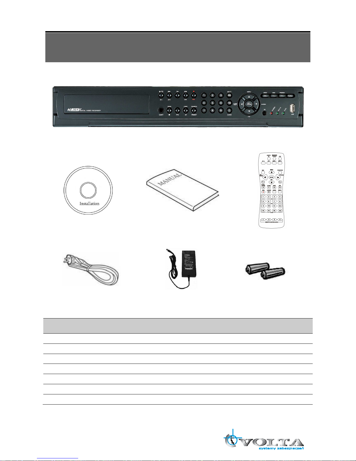
Chapter 2 PACKING DETAIL
1. DVR
2. Client Viewer Software CD 3. User Manual 4. Remote Controller
5. Power Cord 6. Power Adapter 7. Battery
CONTENTS
1. DVR
2. Client Viewer Software CD
3. User Manual
4. Remote Controller
5. Power Cord
6. Power Adapter
7. Battery
3
Chapter 3 LOCATION AND CONTROL
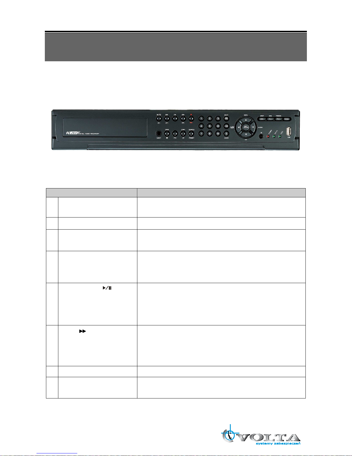
3.1 Front Panel Controls
Item Description
1 DVD-RW
A DVD-RW drive is installed in the front bay. (sold separately)
2 EJECT
Press EJECT button to open/close the DVD-RW drive.
3 IR RECEIVER
Infrared signal receiver for the IR remote controller. Do not block the
receiver as a clear line of sight is required for proper operation.
4 NUMERIC BUTTON /
CHANNEL SELECT
(a) selects a specific channel number to be displayed in full screen
(b) enter the numeric password when prompted
(c) number 0 for audio function
5
PLAY / PAUSE
( )
/ Z(-)
(a) Starts the playback of recorded data. By default, the playback
starts from the earliest recording.
(b) Toggles between playback and pause mode
(c) Zoom out (PTZ mode)
6
FAST
( ) /Z(+)
(a) Fast forward. Press this button repeatedly to toggle between 2X
normal playback speed through 128X normal playback speed.
(b) Zoom in (PTZ mode)
(c) Playback forward, picture by picture.
7
RECORD
()
This button starts and stops the recording mode.
8 STATUS LED
Displays the status of the DVR (standby), HDD read/write and
network transmission.

4
9 ALARM RESET / LEFT
DIRECTION BUTTON
(⊳ )
(a) resets the alarm buzzer
(b) left pans in PTZ mode
(c) navigates left in the menu screen
(d) moves the zoom box left in zoom mode
10 MENU / UP DIRECTIONAL
BUTTON
()
(a) accesses the main menu screen
(b) tilts up in PTZ mode
(c) navigates up in the menu screen
(d) moves the zoom box up in zoom mode
11 PIP / LOOP PLAYBACK
CLEAR / DOWN
DIRECTIONAL BUTTON
()
(a) activates the picture-in-picture mode
(b) tilts down in PTZ mode
(c) navigates down in the menu screen
(d) moves the zoom box down in zoom mode
(e) clears the loop playback in playback mode
12 DIGITAL ZOOM / RIGHT
DIRECTIONAL BUTTON
( )
(a) enters digital zoom mode
(b) pans right in PTZ mode
(c) navigates right in the menu screen
(d) moves the zoom box right in zoom mode
13 USB 2.0 The USB 2.0 port can be used to connect to numerous USB 2.0
backup devices.
14 MULIT
This button is used to toggle between multiple display modes: 16,
13, 10, 9, 7 and 4 channel split screen display modes.
15
SLOW
( )/
IRIS CLOSE /
PIC BY PIC
(a) Slow playback. Press this button repeatedly to toggle between
1/2 normal playback speed through 128 normal playback speed.
(b) Control the iris close in PTZ mode
(c) Playback backward, picture by picture
16 PTZ / BOOKMARK
(a) enters PTZ control mode
(b) creates a bookmark during playback mode
17
DIRECT ION
( )
(a) Change the playback direction.
(b) Control the iris open in PTZ mode
18 COPY / AUTO FOCUS
(a) enters the copy menu screen
(b) switches the PTZ camera to auto focus mode in PTZ mode
19
STOP (■)
Switches the Playback mode to LIVE mode.
20 SEARCH / PRESET
(a) enters the search menu screen
(b) sets the preset positions in PTZ mode
21 SPOT MONITOR / ESC
(a) Activates the spot monitor control
(b) Returns to previous menu screen
(c) Exits from various function and menu screen

5
22 ENTER / STATUS / HOME
(a) executes the selected function in the menu screen or enters the
selected submenu
(b) accesses the status window from the main screen
(c) returns the PTZ camera to “home” mode in PTZ mode
(d) increases the digital zoom ration in zoom mode
23 AUTOMATIC SEQUENCE /
FOCUS OUT / DECREASSE
VALUE / SECTION A
(a) activates and deactivates the automatic channel sequence
(b) focuses out in PTZ mode
(c) decreases the value of a selection in the menu screen
(d) sets the starting point for loop playback in playback mode
24 FREEZE / FOCUS IN /
INCREASE VALUE /
SECTION B
(a) freezes the live screen
(b) focuses in PTZ mode
(c) increase the value of a selection in the menu screen
(d) sets the ending point for loop playback in playback mode
25 FUNCTION
Use with other buttons.
6
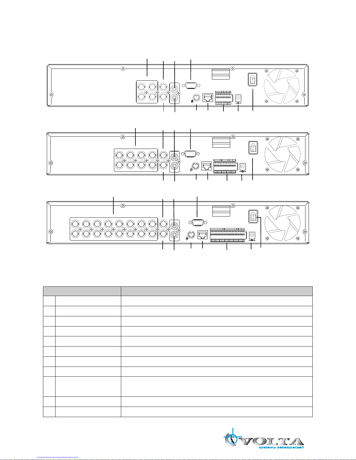
3.2 Real Panel Connectors
4CH DVR
DC 12V
ETHERNET
VGA
ON
OFF
IN
OUT
SPOT3
4
1
2
SENSOR
485
RL1
RISK OF ELECTRIC SHOCK
DO NOT OPEN
TO REDUCE THE RISK OF
FIRE OR ELECTRIC SHOCK
CAUTION !
WARNING:
VIDEO IN
VIDEO OUT
AUDIO
G G
NO
CM
D
+
D
-
3
412
G
G
PS/2
8CH DVR
VGA
ON
OFF
DC 12 V
ETH ERNET
3
4
1
2
7
8
5
6
RIS K OF ELECT RIC SHOC K
DO NOT O PEN
TO RED UCE THE R ISK OF
FIRE O R ELECT RIC SHOC K
CAU TION !
WAR NING:
IN
OUT
SPO T
VID EO OUT
AUD IO
VID EO IN
PS
/2
SENSO R
485
RL1GG
3
412G785
6
NO
CM
D
+
D
-
SENS OR
G
16CH DVR
3
4
1
2
DC 12 V
ON
OFF
ETH ERNET
VGA
7
8
5
6
11
12
9
10
15
16
13
14
RIS K OF ELECT RIC SHOC K
DO NOT O PEN
TO RED UCE THE R ISK OF
FIRE O R ELECT RIC SHOC K
CAU TION !
WAR NING:
IN
OUT
SPO T
VID EO OUT
AUD IO
VID EO IN
PS
/2
SENS OR
485
RL1G
3
412G785
6
11
129101516
13
14
NO
CM
D
+
D
-
GGSENSO R
Item Description
1 VIDEO IN BNC input ports for cameras
2 SPOT BNC output port for spot monitor
3 VIDEO OUT BNC output port for the main monitor
4 AUDIO IN RCA input port for an audio signal
5 AUDIO OUT RCA output port for an audio signal
6 VGA Output port for the VGA monitor
7 PS/2 PS/2 mouse connection port
8 ETHERNET Port for 10/100Mbps Ethernet
9 SENSOR/RS-485/
RELAY OUT
Input terminal blocks for alarm signals/Terminal blocks of RS-485/Relay
output termainal blocks
10 POWER IN Socket for DC 12V power adapter
11 POWER SWITCH Switch to turn the power on/off
1
2
3
4
5
6
7
8
9
10
11
1
2
3
4
5
6
7
8
9
10
11
1
2
3
4
5
6
7
8
9
10
11
7
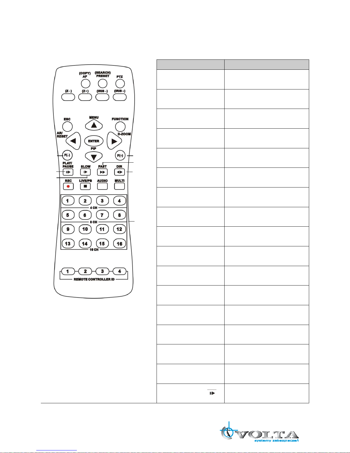
3.3 Remote Controller
Button Name Description
○
,1 COPY/AF
Enter the COPY menu / Auto Focus
Mode (PTZ control mode)
○
,2 (SEARCH) / PRESET
Enter the SEARCH menu / sets the
preset positions in PTZ mode
○
,3 PTZ / BOOKMARK
Enter PTZ control mode / creates a
bookmark during playback mode
○
,4 Z-
Zoom Out (PTZ control mode)
○
,5 Z+
Zoom In (PTZ control mode)
○
,6 IRIS -
Control the iris close in PTZ mode
○
,7 IRIS+
Control the iris open in PTZ mode
○
,8 ESC
Exit / Activates the SPOT monitor
control
○
,9 FUNCTION
Use with other buttons
○
,10 ( ▲ ) / MENU
Up directional button / Enter Menu
Setup
○
,11 AR/ RESET / ( ◀ )
Alarm reset / Left directional button
○
,12 ( ▼ ) / (PIP)
Down directional button / Enter the
PIP mode
○
,13 DIGITAL ZOOM / ( ▶ )
Enter Digital Zoom mode / Right
directional button
○
,14 ENTER
Enter / Enter the STATUS menu
○
,15 F(-)
Decreases the value of a selection /
Activates and deactivates the
automatic channel sequence
○
,16 F(+)
Increases the value of a selection /
Freezes the LIVE screen
○
,17 PLAY / PAUSE ( )
PLAY / PAUSE
Błąd!
Błąd!
Błąd!
Błąd!
Błąd!
Błąd!
Błąd!
Błąd!
Błąd!
Błąd!
Błąd!
Błąd!
Błąd!
Błąd!
Błąd!
Błąd!
Błąd!
Błąd!
Błąd!
Błąd!
Błąd!
Błąd!
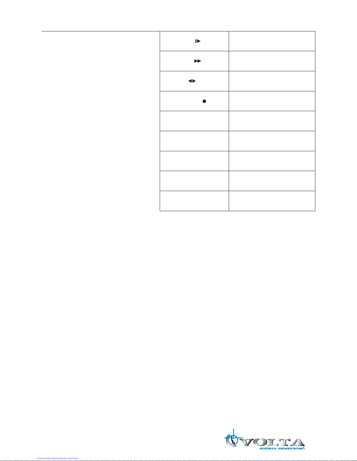
8
○
,18 SLOW ( )
Slow playback
○
,19 FAST ( )
Fast forward
○
,20 DIR ( )
Change the playback direction
○
,21 RECORD ( )
Starts and stops the recording mode
○
,22 LIVE/PB / (■)
Switches the LIVE mode and
Playback mode / STOP
○
,23 AUDIO
Audio function
○
,24 MULTI
Multi display mode
○
,25 CAMERA BUTTONS
Numeric button / Channel select
○
,26
REMOTE CONTROLLER ID
REMOTE CONTROLLER ID
9
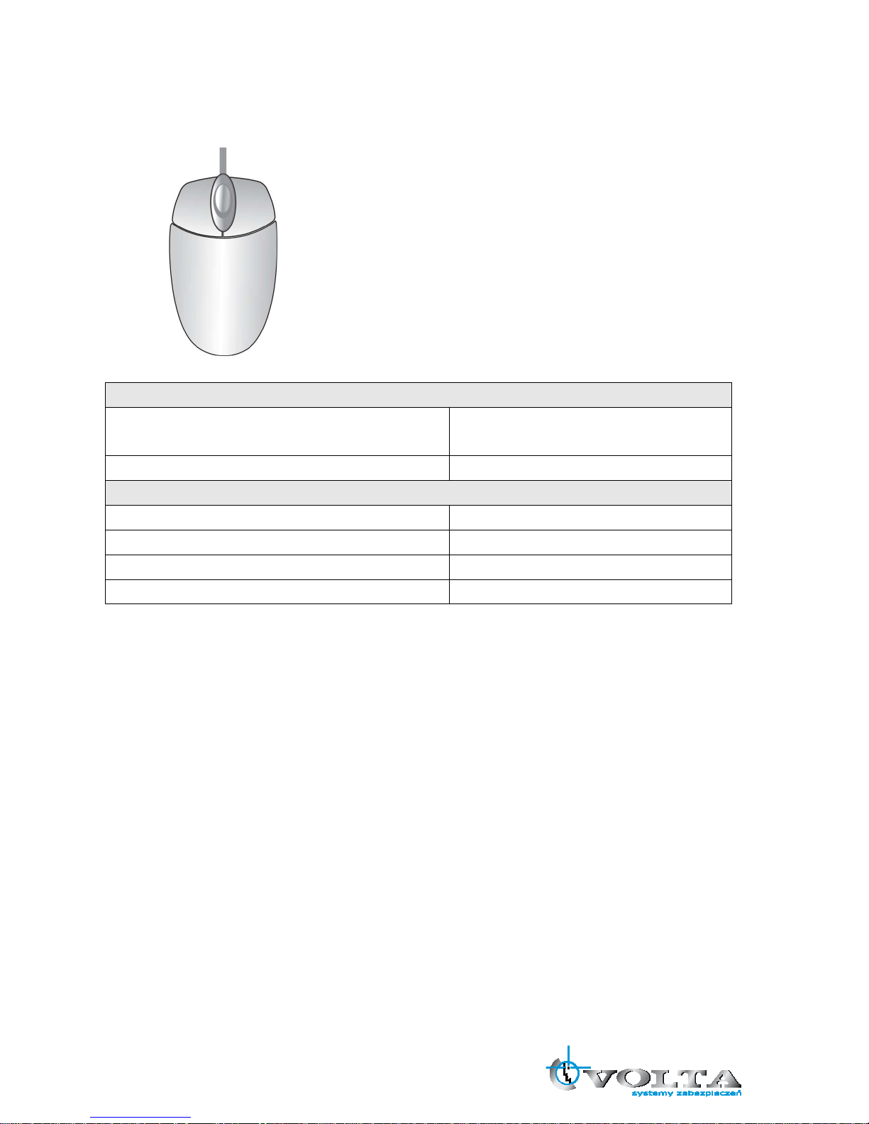
3.4 Mouse Control
LIVE MODE
Single Channel Display Move the cursor to the desired channel and
double left click.
Change from Single-Channel to Multi-ChannelDisplay Double left click
MENU MODE
Enter MENU Right click
Select / Enter Double left click
Return to Previous Page Double right click
Value Change Turning the wheel scroll
10
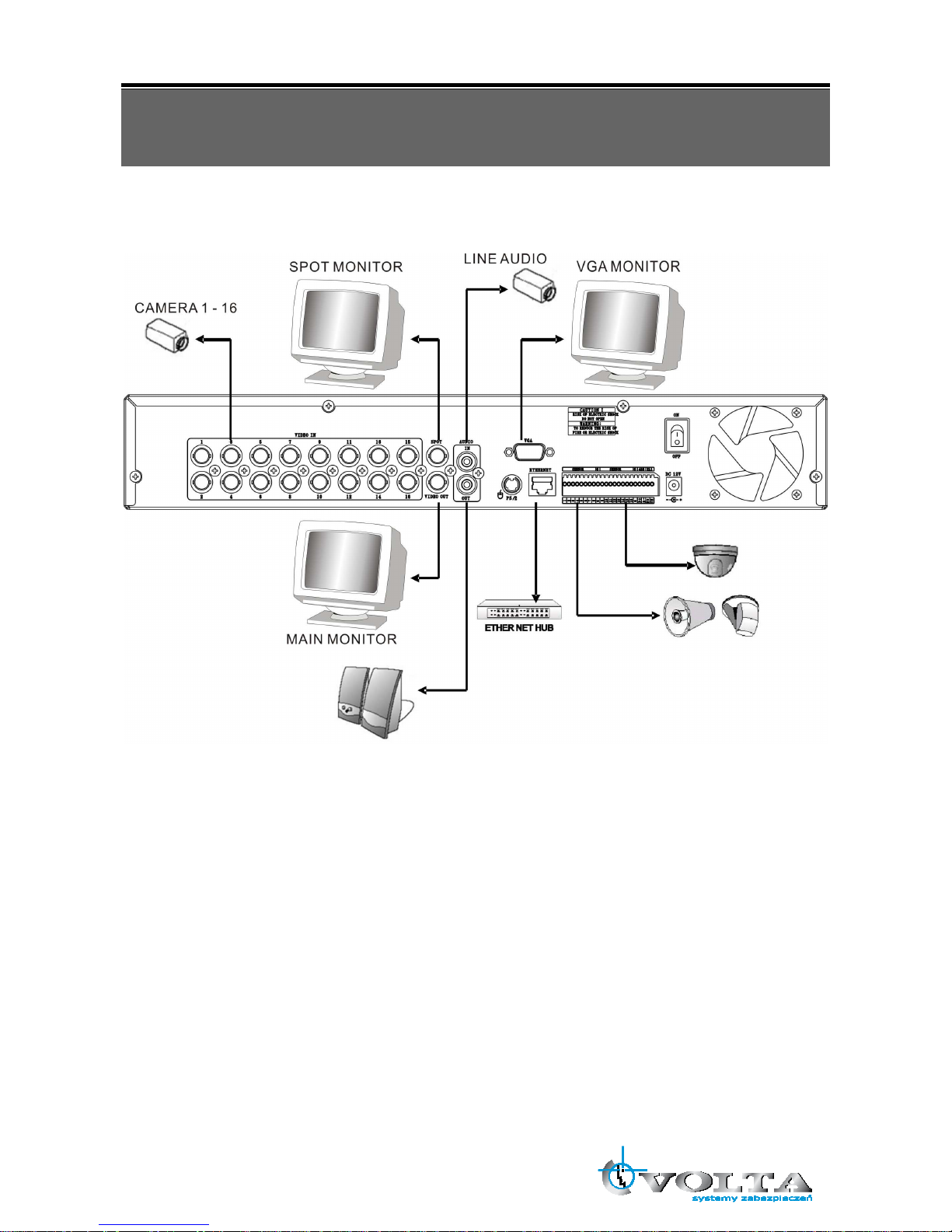
Chapter 4 INSTALLATION
4.1 Total Connection Lay-out
11
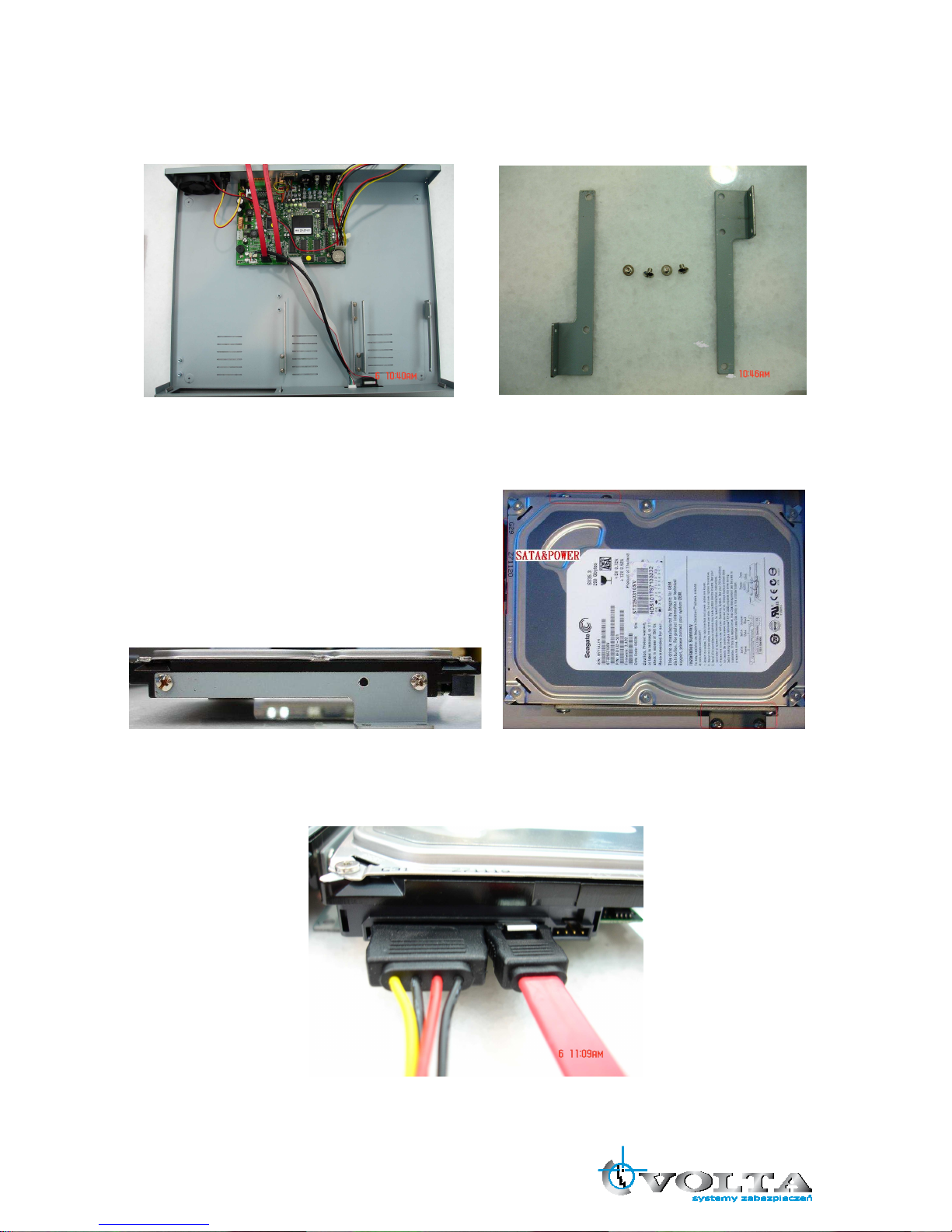
4.2 Hard Disk Installation
First, please remove the HDD holder from the DVR machine. (Pic1)。
(Pic1)
Lock HDD holder symmetirically in the two sides of HDD. (Pic2, Pic3)
(Pic2) (Pic3)
Insert the SATA cable and power cable into SATA HDD. (Pic4)
(Pic4)
12
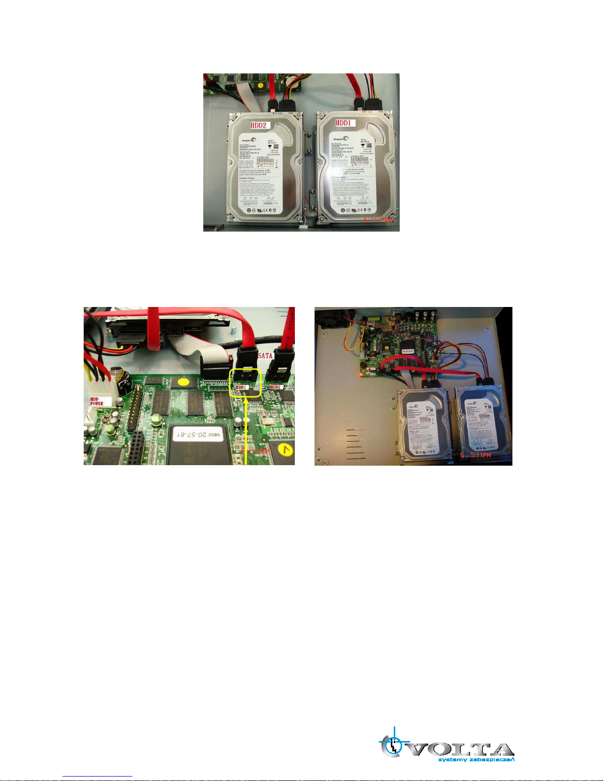
Lock the HDDs onto DVR machine. (Pic5)。
(Pic5)
Insert the SATA cables into the sockets on the main board (Pic6). Make sure the HDD1 cable insert into HDD1
socket. Now, the installation was finished (Pic7).
(Pic6) (Pic7)
13
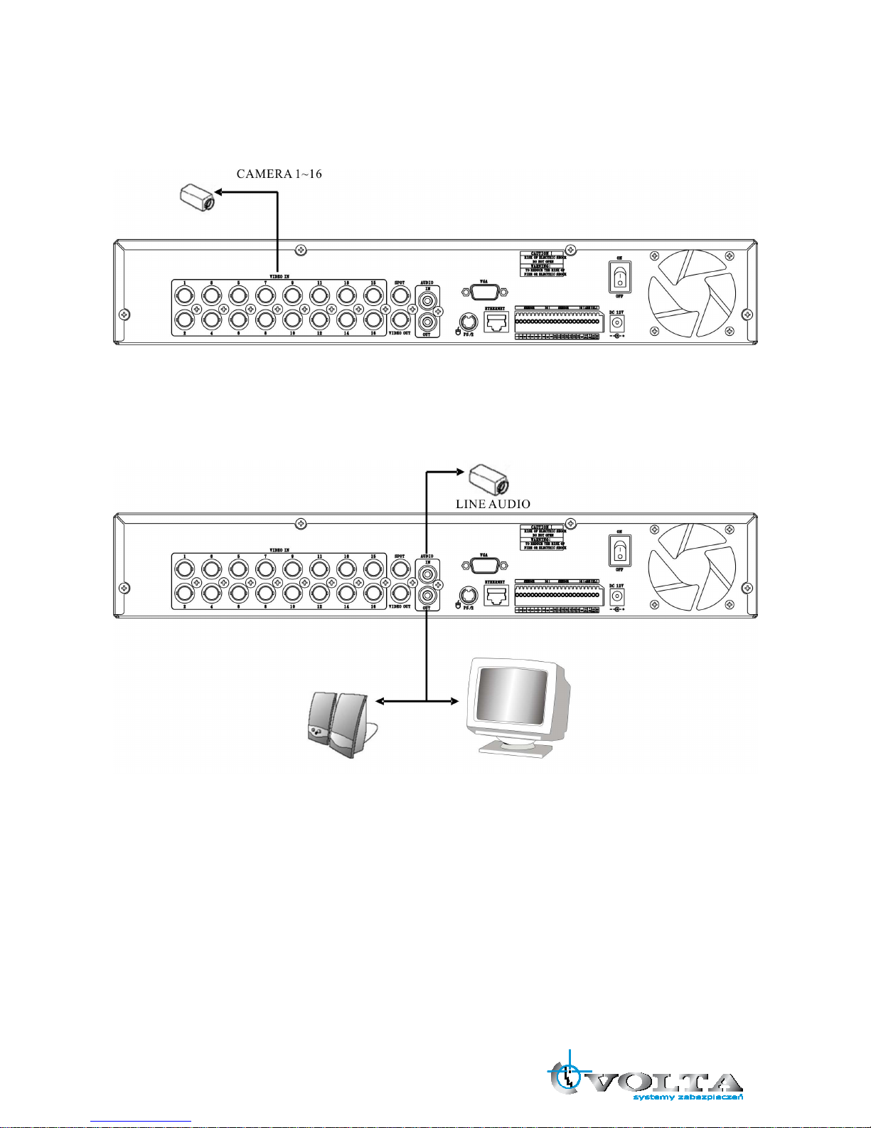
4.3 Main Devices Installtion
4.3.1 Camera
* Connect a female BNC connector of each camera to a male BNC connector, “CAMERA IN” port.
4.3.2 Audio
Audio Input
- AUDIO IN: Connect the RCA Line Jack of the relevant equipment (for example, a camera with a built-in
microphone) to the AUDIO IN port.
Audio Output
- AUDIO OUT: Connect the RCA Line output to a monitor with a built-in speaker.
NOTE
- This DVR can be connected only with a line audio and not support a microphone for audio input and
output. To record audio should be enable in the AUDIO setup at the MENU setup.
- You can hear the audio under LIVE mode and Playback mode. And select any one channel’s audio and
image input from full-screen mode or multi-display mode.

14
4.3.3 Monitor
DVR supports two types of monitor output, one is Composite output (BNC connector); the other one is VGA
output (DSUB-15). But you can just select one monitor output type at a time.
* Composite Output:
(1) Power off
(2) Press the MENU button and CH3 button at the same time
(3) Power on
(4) When you hear a beep sound, it means images already output to the Composite port. Now you can
release the buttons.
* VGA Output:
(1) Power off
(2) Press the MENU button and CH4 button at the same time
(3) Power on
(4) When you hear a beep sound, it means images already output to the VGA port. Now you can release the
buttons.
SPOT MONITOR
MAIN MONITOR
VGA MONITOR
15
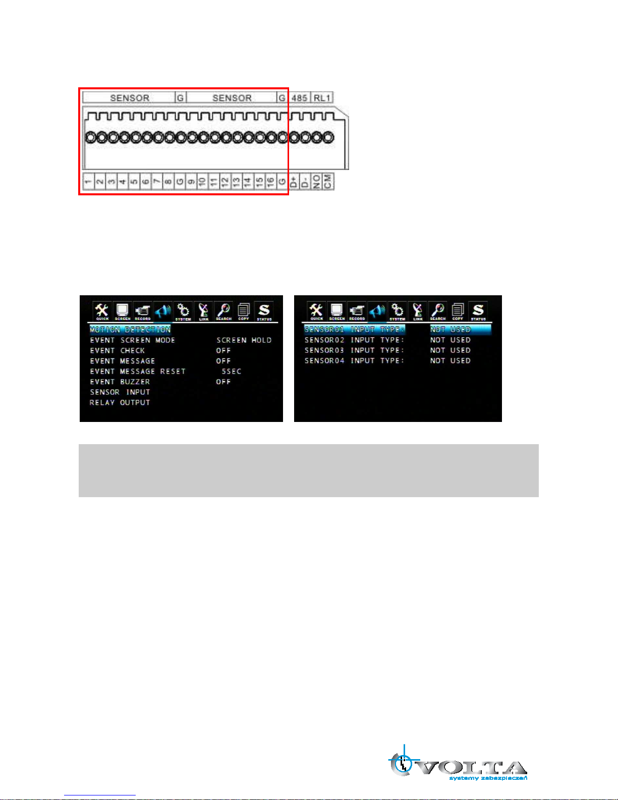
4.4 sensor Input
16CH: SENSOR 1~SENSOR 16
8CH: SENSOR 1~SENSOR 8
4CH: SENSOR 1~SENSOR 4
4.4.1 Sensor Input Menu Setup
Enter EVENT -> SENSOR INPUT menu to select the correct sensor input type which connected with DVR.
Select the right sensor type according to the type of installed sensor with the unit.
- NORMAL OPEN: The sensor is open in normal times.
- NORMAL CLOSE: The sensor is close in normal times.
- NOT USED: No sensors are connected to the DVR unit

16
4.5 RS-485
RS485 is use for connect to external device, such as keyboard or PTZ camera.
4.5.1 RS-485 Menu Setup
Enter LINK -> RS485 menu to set the parameters of RS-485 device which connected with DVR (The
parameters must the same with the device).
4.5.2 PTZ Camera Installation
Connect the PTZ camera to DVR RS-485 interface (D+ to D+; D- to D-), and then connect the camera
output to the desired channel.
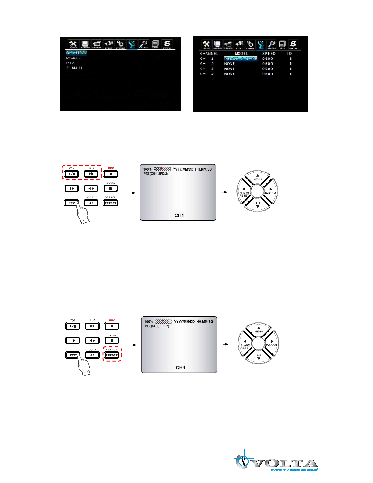
Enter LINK -> PTZ menu to set the parameters of PTZ camera which connected with DVR (The parameters
must be same with PTZ camera).
17
4.5.3 PTZ Camera Operation
1. Select the desired PTZ camera channel.
2. Press the PTZ button to enter the PTZ mode.
3. Use the direction buttons to change camera position.
4. Press Z(+) and Z(-) buttons to control the camera zoom in and zoom out.
5. Press the PTZ button again to exit the PTZ mode.
4.5.4 PTZ Camera Preset Mode
1. Select the desired PTZ camera channel.
2. Press the PTZ button to enter the PTZ mode.
3. Press the PRESET button to enter the “PTZ(PRESET)SET” mode.
4. Use the direction buttons to adjust the camera position you want.
5. Press one number button to remember this preset camera position, for example: press the “1” button, it
means the position of the preset point 1.
6. Press the PRESET button again to enter the “PTZ (PRESET) MOVE” mode.
7. Press the number button, you can move the camera to the preset point you want.
8. Press the PRESET button again to back to the normal PTZ mode.
9. Press the PTZ button again to exit the PTZ mode.
18
Preset point is a convenient usage of PTZ camera. It is a preset user-defined camera position; user can
move the camera position very quickly when needed.
Total programmable capacity of 16 preset locations.
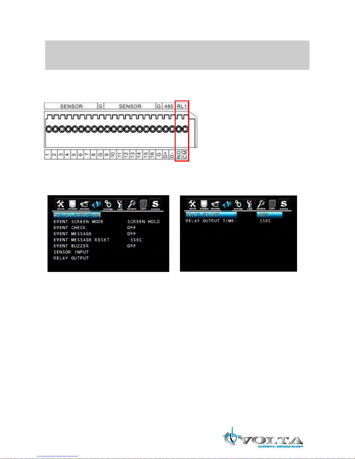
4.6 Relay Output
The relay device should be set to NO (Normal Open) and it will change to NC (Normal Close) when an event
has been triggered.
Enter EVENT -> RELAY OUTPUT menu to select the Relay type which connected with DVR.
DVR provides a relay output interface; the following events will trigger off the relay signal:
RELAY SELECT
<Event Type>
ALARM: Sensor Input
LOSS: Video Loss
MOTION: Motion Detection
RELATY OUTPUT TIME: 1~30 sec.
According to the time set, the buzzer starts beeping while the event is happening.
RELAY SELECT
<System Type>
HDD ERROR: Once hard disk has failed, it will change the relay device to NC.
POWER (NC): Please set the relay device to NC so that once power-loss occurs, it will change to NO.
USER: The relay output can be manully changed. To change NO to NC, press FUNC and then press F(+).
Changing NC to NO, press FUNC and then press F(-).
REC: Once recording has stopped, it will change the relay device to NC.
NOT USED: Disable relay output function.
19
Chapter 5 BASIC OPERATION AND MENU SETUP
5.1 Basic Operation
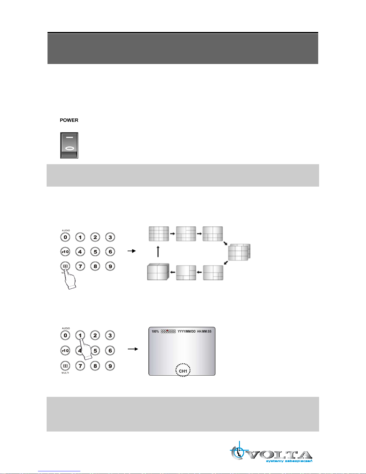
5.1.1 Power ON/OFF
After the connection of power adaptor and other devices (HDDS) with this DVR, turn the power on.
a. The video signal system (NTSC or PAL) is automatically detected.
b. Power Failure Recovery
This DVR automatically reverts back to programmed record parameters upon power
restoration.
If there is no video signal, the video signal system is set to NTSC. Do not input the PAL type video signal or
it may cause the DVR’s malfunction. In this case, turn off and on again.
5.1.2 Screen Display
a. Multi display
To change a single camera display to the multi camera, press the MULTI button.
b. Full screen display
Press the desired camera number button to display on the monitor.
NOTE:
-Use the +10 Button when you select two digit camera numbers.
EX) Camera Number 12 = Press the +10 Button, and then press the No. 2 Button.
-CAMERA/NUMBER INPUT buttons are used to input the password in the password lock function as well.
20
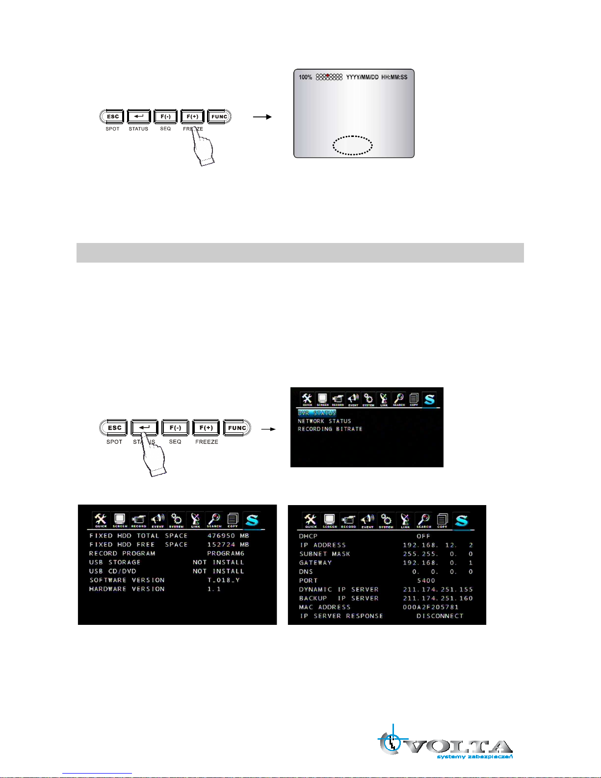
c. Freeze
This function allows users to freeze live view mode at any given time. 4CH DVR supports only single screen
mode. Press [FREEZE] at single screen mode to freeze the image and press again to release this function.
8/16CH DVR can support both single and multi screen mode. The operation is the same as 4CH DVR for
single screen mode. For multi screen mode, press [FREEZE] at multi live screen, the message will be
shown at upper-left, but no channels will freezed. Then press the channel users want to freeze, the
message will be shown at camera title. Press next channel to stop others. Press [FREEZE] again to release
this function.
- FREEZE function is not available, when auto mode is selected.
d. LIVE/Playback mode switching
Press the LV/PB (■) button in the Playback mode, you can switch to the LIVE monitoring mode.
5.1.3 System Status
① Press the “STATUS” button, the SYSTEM STATUS menu will appear.
② Select the item you want: DVR Status, Network Status or Recording Bitrate, you can see the detail
information.
③ Press the “ESC” button to exit the menu.
DVR status: Network status:
* Please refer to 9.1 Network Setup.
Recording Bitrate:
FREEZE
 Loading...