


Betriebsanleitung
Operating Instructions
Dampfstation / Steam Station 12 kW
Dampfstation / Steam Station 26 kW
Dampfstation / Steam Station 39 kW
Dampfstation / Steam Station 52 kW
VEIT 2380

Dampfstation VEIT 2380 12 kW / 26 kW / 39 kW / 52 kW
VEIT 2380 Steam Station 12 kW / 26 kW / 39 kW / 52 kW
VEIT GmbH
Justus-von-Liebig-Str. 15
D - 86899 Landsberg am Lech
Germany
Phone +49 (81 91) 479 0
Fax +49 (81 91) 479 149
www.veit-group.com
Service Hotline
Germany: +49 (81 91) 479 133
Europe: +49 (81 91) 479 252
America: +1 (770) 868 8060
Asia: +852 2111 9795
Ersatzteile/Spare Parts
Vertrieb/Sales +49 (8191) 479 176
Vertrieb Textilpflege/ +49 (8191) 479 129
Sales Textile care
31.01.2007 2

Dampfstation VEIT 2380 12 kW / 26 kW / 39 kW / 52 kW
VEIT 2380 Steam Station 12 kW / 26 kW / 39 kW / 52 kW
Inhaltsverzeichnis / Table of Contents:
1 Betriebsanleitung / Operating Instructions 4
1.1 Warnhinweise / Safety Instructions 4
1.2 Technische Daten / Technical Data 4
1.3 Vorschriften / Regulations 5
1.4 Aufstellung und Anschluss / Installation and Connection 5
1.5 Arbeitsweise, Sicherheit und Störungsbeistand / Mode of Oper ation , Safety and
1.6 Inbetriebnahme / Commissioning and Start-up 8
1.7 Prüf- und Wartungsarbeiten / Inspection and Maintenance Work 9
1.8 Wartungsplan / Maintenance Schedule 11
b
Trou leshooting 6
Arbeitsweise / Mode of Operation 6
1.5.1
1.5.2 Sicherheitseinrichtungen / Safety Devices 7
1.5.3 Störungsbeistand / Troubleshooting 7
1.6.1 Betrieb / Operating 9
2 Ersatzteile / Spare Parts 13
2.1 Zeichnungen / Drawings 13
2.2 Ersatzteilliste / Spare Parts List 16
3 Zeichnung der Anschlüsse / Drawing of the
Connections 18
4 Merkblatt / Information Leaflet 2380-001 19
5 Merkblatt / Information Leaflet 2380-002 20
6 Schaltpläne / Circuit Diagrams 21
6.1 12 kW / 400 V, 50 Hz 21
6.2 26 kW / 400 V, 50 Hz 26
6.3 39 kW / 400 V, 50 Hz 31
6.4 52 kW / 400 V, 50 Hz 36
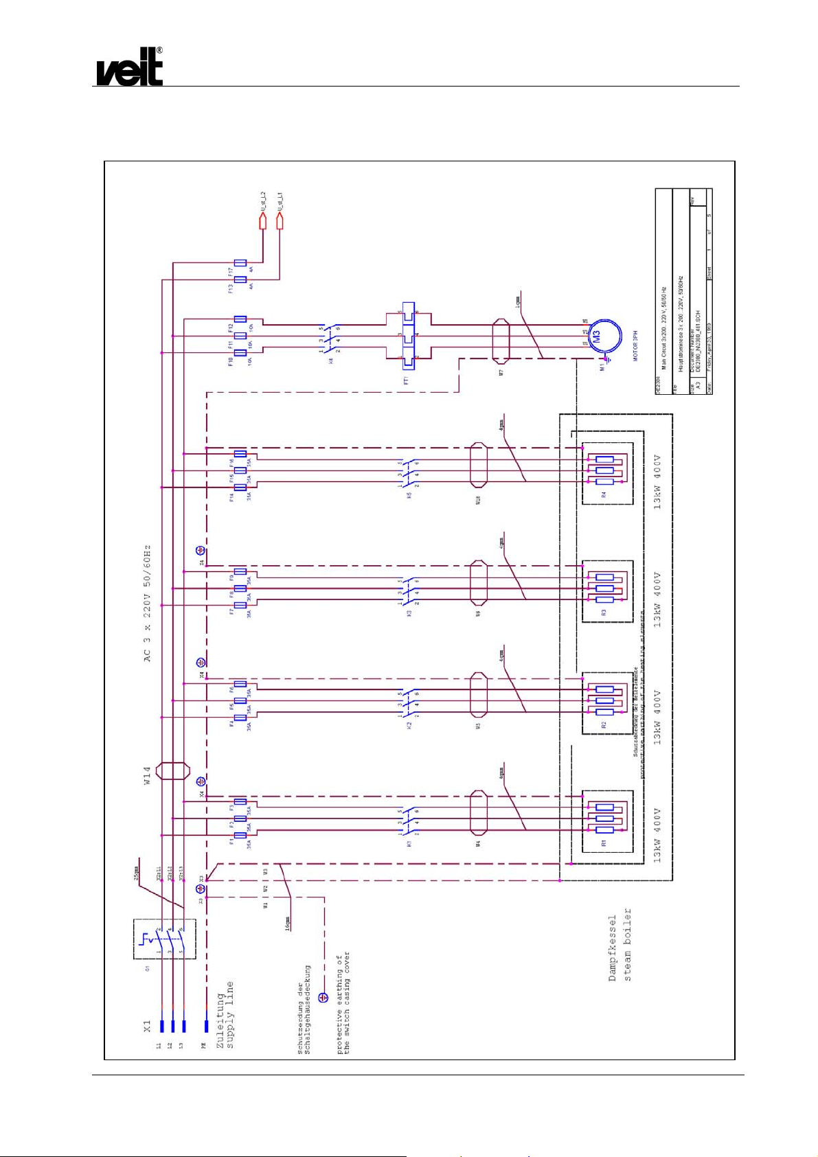
6.5 36 kW / 3x200-220 V, 50/60 Hz 41
6.6 48 kW / 3x200-220 V, 50/60 Hz 46
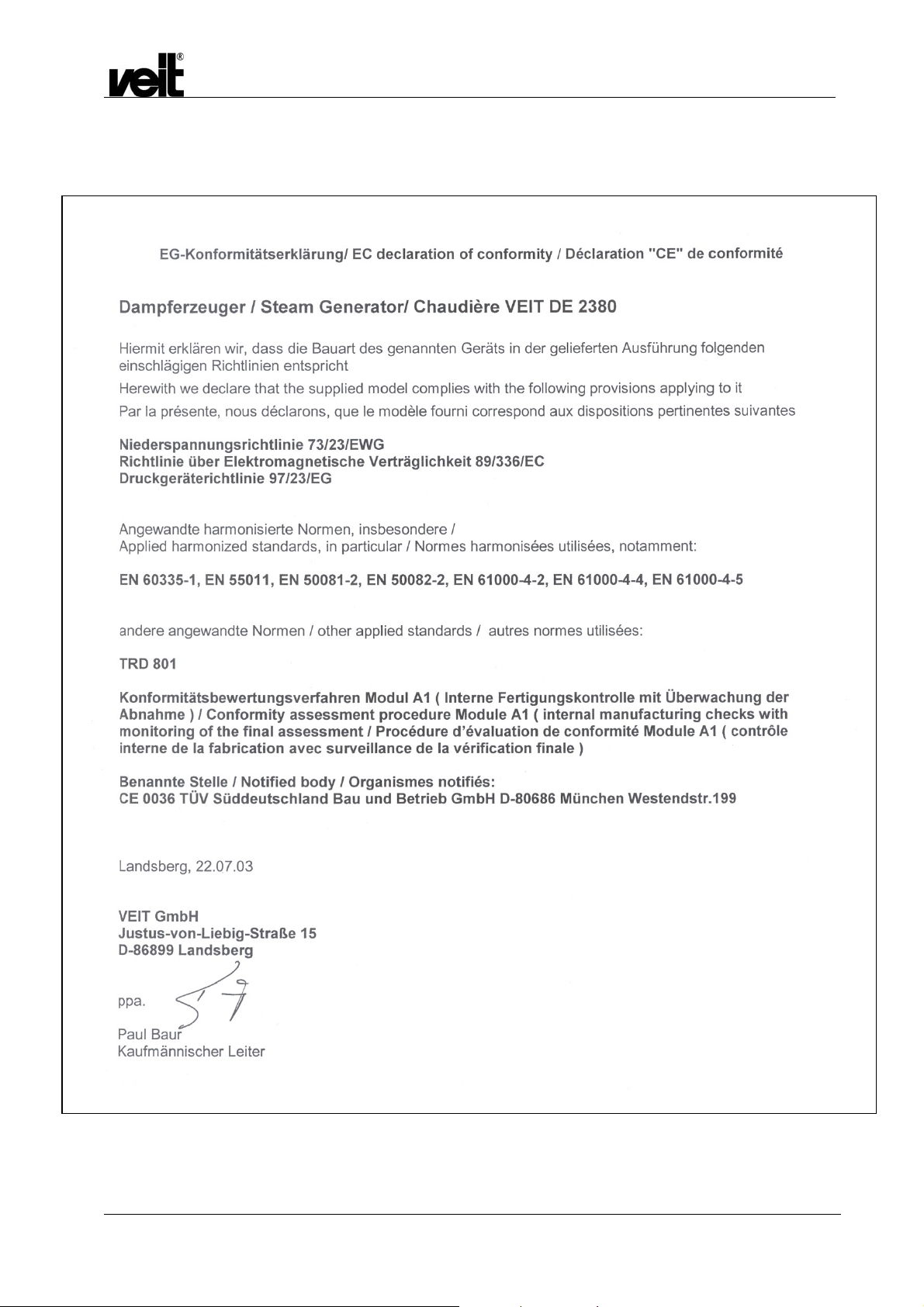
7 EG-Konformitätserklärung / EC Declaration of
conformity 51
31.01.2007 3

1 Betriebsanleitung / Operating Instructions
1.1 Warnhinweise / Safety Instructions
Dampfstation VEIT 2380 12 kW / 26 kW / 39 kW / 52 kW
VEIT 2380 Steam Station 12 kW / 26 kW / 39 kW / 52 kW
STÖRUNGEN AN DER ELEKTRISCHEN ANLAGE DÜRFEN
NUR DURCH ELEKTROFACHKRÄFTE BEHOBEN WERDEN.
VOR ÖFFNEN DES GERÄTES HAUPTSCHALTER IN
STELLUNG „0“ BRINGEN UND GEGEBENENFALLS
ABSCHLIESSEN.
BEI LÄNGEREN BETRIEBSPAUSEN ABSPERRHAHN DER
SPEISEWASSERZUFUHR SCHLIESSEN.
GEFAHR VON WASSERSCHÄDEN!
DAS GERÄT VOR FROST SCHÜTZEN.
ELECTRICAL FAULTS MUST ONLY BE REPAIRED BY
AUTHORIZED PERSONNEL.
BEFORE OPENING THE UNIT, TURN THE MAIN SWITCH TO
POSITION "0" AND LOCK, IF NECESSARY.
DURING LONGER OPERATION BRAKE CLOSE THE STOP
COCK OF THE FEED WATER.
DANGEROUS OF WATER DAMAGE!
PROTECT THE UNIT FROM FROST.
1.2 Technische Daten / Technical Data
Elektrischer Anschluss
Elektrischer Anschlusswert
Heizleistung 2-3stufig
Heizfläche
Sattdampfleistung
Zulässiger Betriebsüberdruck
Eingestellter Betriebsdruck
Wasserinhalt NW
Kesselvolumen
Speisewassertemperatur max.
Speisewassertemperatur max.
bei Geräten mit Sonderpumpe
(Sonderanfertigung)
Anschlüsse:
Dampf
Kondensat
Wasser
Überlauf
Speisewassergefäß
Überlauf
Abschlämmbehälter
Abmessungen:
Länge
Breite
Höhe
Baujahr:
Electrical connection
Connected load
Heating capacity 2 to 3-stage
Heating surface
Saturated steam capacity
Admissible working overpressure
Adjusted working pressure
Water content min. water level
Boiler content
Feed water temperature max.
Feed water temperature max. at
steam stations with special pump
(special production)
Connections:
Steam
Condensate
Water
Overflow feed water tank
Overflow drainage tank
Dimensions:
Length:
Width:
Height:
Year of construction:
siehe Typenschild
kW 12 26 39 52
kW 6 13 13 26
12 26 26
dm² 9,3 10,6 16 21,2
kg/h 15 34 51 68
bar 7 7 7 7
bar 6 6 6 6
l 9,9 9,9 9,9 9,9
l 27 27 27 27
°C 70 70 70 70
°C 90 90
Kugelhahn 1/2"
1/2"
Kugelhahn 3/8"
1/2"
3/4"
mm 630
mm 930
mm 1130
siehe Typenschild
See machine-plate
39
Ball valve 1/2"
Ball valve 3/8“
See machine-plate
52
31.01.2007 4

1.3 Vorschriften / Regulations
Dampfstation VEIT 2380 12 kW / 26 kW / 39 kW / 52 kW
VEIT 2380 Steam Station 12 kW / 26 kW / 39 kW / 52 kW
Die VEIT 2380 Dampfstation mit elektrischer
Widerstandsheizung wird zur Erzeugung von Wasserdampf für
industrielle und gewerbliche Zwecke verwendet.
Der eingebaute Dampfkessel der Gruppe I (TRD 801) ist
hergestellt gemäß der "Verordnung über Dampfkesselanlagen
(Dampfkesselverordnung) vom 27. Februar 1980-BGBI.I“, Seite
173. Die Voraussetzungen nach § 12 Abs. 1 der
Dampfkesselverordnung sind somit erfüllt.
In der Bundesrepublik Deutschland bedarf diese Dampfstation
nicht der Erlaubnis zur Errichtung und zum Betrieb.
Der Dampferzeuger entspricht der Kategorie II der DruckgeräteRichtlinie (97/23/EG) und wurde zertifiziert von der
Zertifizierungsstelle TÜV Süddeutschland Bau und Betriebs
GmbH – CE0036.
In der Dokumententasche, die außen am Gerät angebracht ist,
befinden sich das Zertifikat über die Wasserdruckprüfung und
die Bescheinigung über die ordnungsgemäße Installation der
Dampfkesselanlage.
Die elektrische Ausrüstung des Dampfkessels entspricht den
einschlägigen VDE-Bestimmungen. Der örtliche Anschluss hat
nach den technischen Anschlussbestimmungen (TAB) des
zuständigen Elektroversorgungsunternehmens zu erfolgen.
The VEIT 2380 steam station with electrical resistance heating is
used to produce water steam for industrial use.
The built-in steam boiler of the group I (TRD 801) is
manufactured according to the "Regulations for steam boiler
units" ("Dampfkesselverordnung") effective from 27th February
1980, BGBl.I, page 173, so meeting the requirements under § 12
I of this regulation.
In the Federal Republic of Germany no permission is required to
install and to operate this steam station.
The Steam Boiler category II in compliance with “Pressure
equipment directive” (97/23/EG) certification agency “TÜV
Süddeutschland Bau und Betriebs GmbH” – CE0036.
In the document-box, attached to the side of the unit, you will find
the certificate for the water pressure test and the certificate of the
proper installation of the steam boiler unit.
The electrical equipment of the steam boiler meets the relevant
VDE-regulations. The local connection must be made according
to the technical regulations (TAB) of the responsible electric
supplier.
1.4 Aufstellung und Anschluss / Installation and Connection
Die Dampfstation VEIT 2380 wird als anschlussbereites Gerät
geliefert. Sie ist mit allen erforderlichen Sicherheits- und
Bedienvorrichtungen ausgerüstet. Das Speisewassergefäß und
der Abschlämmbehälter sind im selben Gehäuse untergebracht
und fest mit dem Kessel verbunden.
Die Dampfstation ist an einem Platz zu installieren, an dem eine
einwandfreie Bedienung und Zugänglichkeit zu allen Armaturen
gewährleistet ist.
Sie muss so aufgestellt werden, dass aus den daran
angeschlossenen Geräten kein Dampf auf die Dampfstation
einwirken kann. Gefahr von Schäden in der Elektrik!
Die Anschlussleitungen (Elektrokabel, Kondensat,
Speisewasser) sind so zu verlegen, dass sie keine Stolperfallen
darstellen.
Der Dampferzeuger ist für den Betrieb mit normalem oder
enthärtetem Leitungswasser geeignet. Bei Zusatz von
Chemikalien übernimmt VEIT keine Haftung für Funktion und
Sicherheit des Geräts.
Folgende Anschlüsse sind erforderlich:
• Speisewasseranschluss:
Für die druckführende Leitung zum Speisewasserbehälter
wird eine starre Verrohrung empfohlen. Für das letzte Stück
zum Gerät kann auch ein Panzerschlauch verwendet
werden. Wir empfehlen 1 m, maximal jedoch 3 m
Panzerschlauch. Der Panzerschlauch muss für den
maximalen Leitungsdruck geeignet sein. Keinesfalls dürfen
flexible, ungeschützte Schläuche und Schlauchklemmen
verwendet werden.
Am Übergang von der starren Verrohrung zum
Panzerschlauch ist ein Absperrhahn vorzusehen.
Die Wasserhärte darf 4°dH nicht überschreiten. Die
Temperatur darf nicht höher sein als 70°C (bei Geräten mit
Sonderpumpe [Sonderanfertigung] nicht höher als 90°C). Bei
höheren Wasserhärten empfiehlt sich die Verwendung einer
Wasserenthärtungsanlage (z.B. VEIT 3307). Bei höheren
Wassertemperaturen siehe Punkt 1.5 Arbeitsweise,
Sicherheit und Störungsbeistand.
The VEIT 2380 steam station is ready to be connected when it is
delivered. It is equipped with all necessary safety and operating
devices. The feed water tank and the drainage tank are
assembled in the same casing and are directly connected to the
boiler.
The steam station is to be installed at a place where it can be
operated properly and with easy access to all mountings.
The steam station must be installed that way that from the
devices, which are connected to the steam station, no steam can
have an effect on the steam station. Danger of damage to the
electrics!
The connection lines (electro cable, condensate, feedwater)
must be laid that way that these lines cannot be tripped over.
The steam generator is suited for operation with normal or
softened tap water. If other chemicals are added, VEIT bears no
responsibility for any resulting damage and for the function and
safety of the machine
The following connections are necessary:
• Feed water connection:
For the pressurised pipe to the feed water tank we
recommend a fixed piping. For the last distance to the unit
an armoured tube can be used. The length of this armoured
tube should be between 1 and 3 meters. It must be adapted
for the maximum pressure. Never use flexible, unprotected
hoses and hose clips.
At the transition of the fixed piping to the armoured tube a
stop cock is to be planned.
The water hardness must not exceed 4° dH (German
hardness). The temperature must not be higher than 70°C
(at Steam Stations with special pump [special production] not
be higher than 90°C). If the water hardness is higher, a
water-softening unit (for example VEIT 3307) is
recommended. See section 5 for higher water temperatures.
31.01.2007 5

• Kondensatanschluss:
Die Kondensatleitung wird an den Kondensatstutzen des
Speisewassergefäßes angeschlossen. (mittelbar - über die
automatische Speisewassertemperaturregelung).
• Überlauf:
Die Überlaufstutzen des Speisewassergefäßes und des
Abschlämmbehälters werden getrennt an einen Gully mit
ausreichenden Querschnitt geführt.
• Kugelhahn für Speisewasser-Entleerung:
Wird auch an den Gully angeschlossen.
Für die oben genannten Anschlüsse, siehe auch Kapitel 3
Zeichnung der Anschlüsse.
• Elektrischer Anschluss:
Als Anschlusskabel empfehlen wir eine schwere
Gummischlauchleitung H 07 RNF 5G16. Das Kabel wird
durch die PG 36-Verschraubung mit Zugentlastung geführt
und an den Hauptschalter angeschlossen. Das Kabel soll am
Rahmen des Gerätes mit Kabelbinder befestigt werden.
Der Elektroanschluss darf nur von einem zugelassenen
Elektrofachmann unter Beachtung der VDE- und
örtlichen Vorschriften ausgeführt werden.
Dampfstation VEIT 2380 12 kW / 26 kW / 39 kW / 52 kW
VEIT 2380 Steam Station 12 kW / 26 kW / 39 kW / 52 kW
• Condensate connection:
The condensate line is connected to the condensate plinth of
the feed water tank (indirectly by the automatic feed water
temperature control).
• Overflow:
The overflow plinths of the feed water tank and of the
drainage tank are separately led to a gully hole with sufficient
cross section.
• Ball valve for emptying the feed water:
This ball valve is also connected to the gully hole.
For the a.m. connections, see also the drawing section 3.
• Electrical connection:
A heavy rubber sheathed cable H 07 RNF 5G16 is
recommended as connection cable. The cable is led through
the PG 36-union joint with strain relief and is connected to
the main switch. The cable should be fixed by cable straps at
the frame of the unit.
The electrical connection must be performed only by
authorized personnel observing the VDE and local
regulations.
1.5 Arbeitsweise, Sicherheit und Störungsbeistand / Mode of Operation, Safety and
Troubleshooting
1.5.1 Arbeitsweise / Mode of Operation
Das Speisewasser wird von der Pumpe in den Kessel gefördert.
Der Wasserstand im Kessel wird durch eine elektronische
Steuerung geregelt, welche die Pumpe ein- und ausschaltet.
Während die Pumpe läuft, leuchtet die rote Kontrolllampe
„Pumpe“.
Der Wasserstand wird mit 3 Kontrolllampen auf der Frontplatte
angezeigt:
Rote LED „zu niedrig“: leuchtet, wenn sich der Wasserstand
unterhalb NW befindet. In diesem Fall läuft die Pumpe an.
Grüne LED „normal“: leuchtet nach Überschreiten des
Wasserstandes NW auf. Die Pumpe läuft noch eine gewisse Zeit
nach.
Gelbe LED „max.“ leuchtet bei Erreichen des Wasserstands HW.
Die Pumpe läuft nicht mehr.
Die Dampferzeugung erfolgt über Widerstandsheizkörper, die
von einem Druckregler und der Elektronik gesteuert werden.
Über die Schalter „Leistung“ können die im Pkt.2 angegebenen
Heizleistungsstufen gewählt werden.
The feed water is supplied by the pump to the boiler.
The water level in the boiler is regulated by an electronic control,
which switches the pump on and off. When the pump operates,
the red control lamp "pump" lights.
The water level is indicated by three control lamps on the front
plate:
The red LED "too low" lights, if the water level is lower than the
minimum water level. In this case the pump starts working.
The green LED "normal" lights when the minimum water level is
exceeded. The pump still works for some time.
The yellow LED "max" lights when the maximum water level is
reached. The pump does not work any longer.
The steam is produced with resistance heating elements, which
are controlled by a pressure regulator and of the electronics.
The heating capacities mentioned under section 2 can be
selected using the switches "Capacity" ("Leistung").
31.01.2007 6

Dampfstation VEIT 2380 12 kW / 26 kW / 39 kW / 52 kW
1.5.2 Sicherheitseinrichtungen / Safety Devices
Ein TÜV-geprüftes Sicherheitsventil verhindert ein Überschreiten
des zulässigen Betriebsüberdruckes von 7 bar.
Als Übertemperatursicherung wird ein TÜV-geprüfter
Sicherheitstemperaturbegrenzer verwendet. Der Messfühler des
Begrenzers befindet sich in einer Tauchhülse genau über der
mittleren Heizung. Der Begrenzer unterbricht die Stromzufuhr bei
Erreichen einer Grenztemperatur von 235°C.
Unterbrechung muss unbedingt die Ursache der Unterbrechung
gesucht werden. Erst danach darf der Begrenzer zurückgestellt
werden.
Die Speisewasserpumpe wird über ein Motorschutzrelais gegen
Überlast geschützt
Die Pumpenlaufzeit wird von der Elektronik überwacht. Beim
Überschreiten einer vorgegebenen maximalen Zeit wird eine
Störmeldung ausgelöst. Die rote LED „Behälter leer“ und der
„Reset-Taster blinken; außerdem wird ein akustisches Signal
ausgelöst. Eine Quittierung dieser Störung löst eine neue
Laufzeit der Pumpe aus. Die Ursache der Störung muss
behoben werden, siehe Kapitel 1.5.3 Störungsbeistand.
1.5.3 Störungsbeistand / Troubleshooting
1.5.3.1 Störungsmeldung Pumpe / Fault indicator on the pump
Blinken die rote LED „Behälter leer“ sowie der „Reset-Taster,
liegt eine Störung des Pumpenkreislaufs vor.
Die Störung muss durch Betätigen der „Reset-Taste quittiert
werden.
Wenn die Pumpe nach der Stör-Quittierung nicht anläuft, ist die
Ursache der Störung im elektrischen Kreis der Pumpe zu
suchen.
Läuft die Pumpe an, dann können folgende Störungsursachen
vorliegen:
• Speisewasser-Behälter leer
• Schmutzfänger am Speisewasser-Behälter verstopft
• Wasser Elektromagnetventil defekt
• Rückschlagventil defekt
• Befüll-Leitung verstopft
Die maximale Laufzeit der Pumpe kann auch durch eine zu hohe
Speisewasser-Temperatur überschritten werden, siehe Kapitel
1.5.3.2 Störung Speisewassertemperatur.
1.5.3.2 Störung Speisewassertemperatur / Excessive feed water temperature
Die Speisewassertemperatur darf nicht höher als 70°C (bei
Dampfstationen mit Sonderpumpe [Sonderanfertigung] nicht
höher als 90°C) sein. Bei Überschreiten dieses Wertes wird eine
Störmeldung ausgelöst. Die „Speisewasser-Temperatur“Anzeige und der „Reset-Taster blinken; außerdem wird ein
akustisches Signal ausgelöst.
Nach der Störquittierung muss Wasser aus dem SpeisewasserBehälter abgeführt werden, so dass kaltes Frischwasser
einfließen kann.
Nach der
VEIT 2380 Steam Station 12 kW / 26 kW / 39 kW / 52 kW
A TÜV (German safety standards regulations)-tested safety
valve prevents the permitted working overpressure of 7 bars
from being exceeded.
A TÜV-tested safety temperature limiter is used as a fuse for
overheating. The sensor of the limiter is in a tube exactly over
the middle-heating element. The limiter interrupts the current
supply the temperature has risen to 235°C.
the cause must be found immediately and only then may the
limiter be reset.
The feed water pump is protected against overload by a motor
protection relay.
The working time of the pump is measured by the electronics. A
fault indicator is released, when a preset maximum time has
been exceeded. The red LED "Tank empty" ("Behälter leer") and
the "reset" key flash; additionally an acoustic signal is released.
When this fault has been acknowledged, a new working time of
the pump is set. The failure must be repaired, see 1.5.3.
If the red LED "Tank empty" ("Behälter leer") and the "reset" key
flash, the pump system is faulty.
The fault must be acknowledged by actuating the "reset" key.
If the pump does not start working after the fault has been
acknowledged, check the electrical system of the pump.
If the pump starts working, the causes of the fault can be:
• feed water tank is empty
• dirt trap in the feed water tank is blocked
• defective water electric solenoid valve
• check valve defective
• filling line blocked
The maximum working time of the pump can also be exceeded,
if the feed water temperature is too high; see 1.5.3.2.
In case the pump has a defect, please read point 10 (page 16),
point 6 (page 13) and figure F picture/illustration C (page 75) in
the enclosed operating instructions for the pump.
If you need the customer service, please call VEIT (telephone
number: +49 (81 91) 479 - 252) or the company Grundfos
(telephone number on the back of the enclosed operating
instructions for the pump).
The feed water temperature must not exceed 70°C (at Steam
Stations with special pump [special production] 90°C) and, if it
does, a fault indication is released. The "feed water temperature"
indicator and the "reset" key flash and an acoustic signal is
released as well.
After the fault has been acknowledged, some water must be
drained from the feed water tank to allow cold fresh water to flow
in.
After the interruption
31.01.2007 7
1.6 Inbetriebnahme / Commissioning and Start-up
Dampfstation VEIT 2380 12 kW / 26 kW / 39 kW / 52 kW
VEIT 2380 Steam Station 12 kW / 26 kW / 39 kW / 52 kW
Bei der ersten Inbetriebnahme bitte folgendes beachten :
• Der elektrische Anschluss ist zu überprüfen. Die
Drehrichtung des Pumpenmotors prüfen, bei falscher
Drehrichtung sind zwei Phasen zu tauschen.
• Speisewassergefäß befüllen.
• Achtung! Gilt nur für Dampfstationen mit Sonderpumpe
(Sonderanfertigung)!
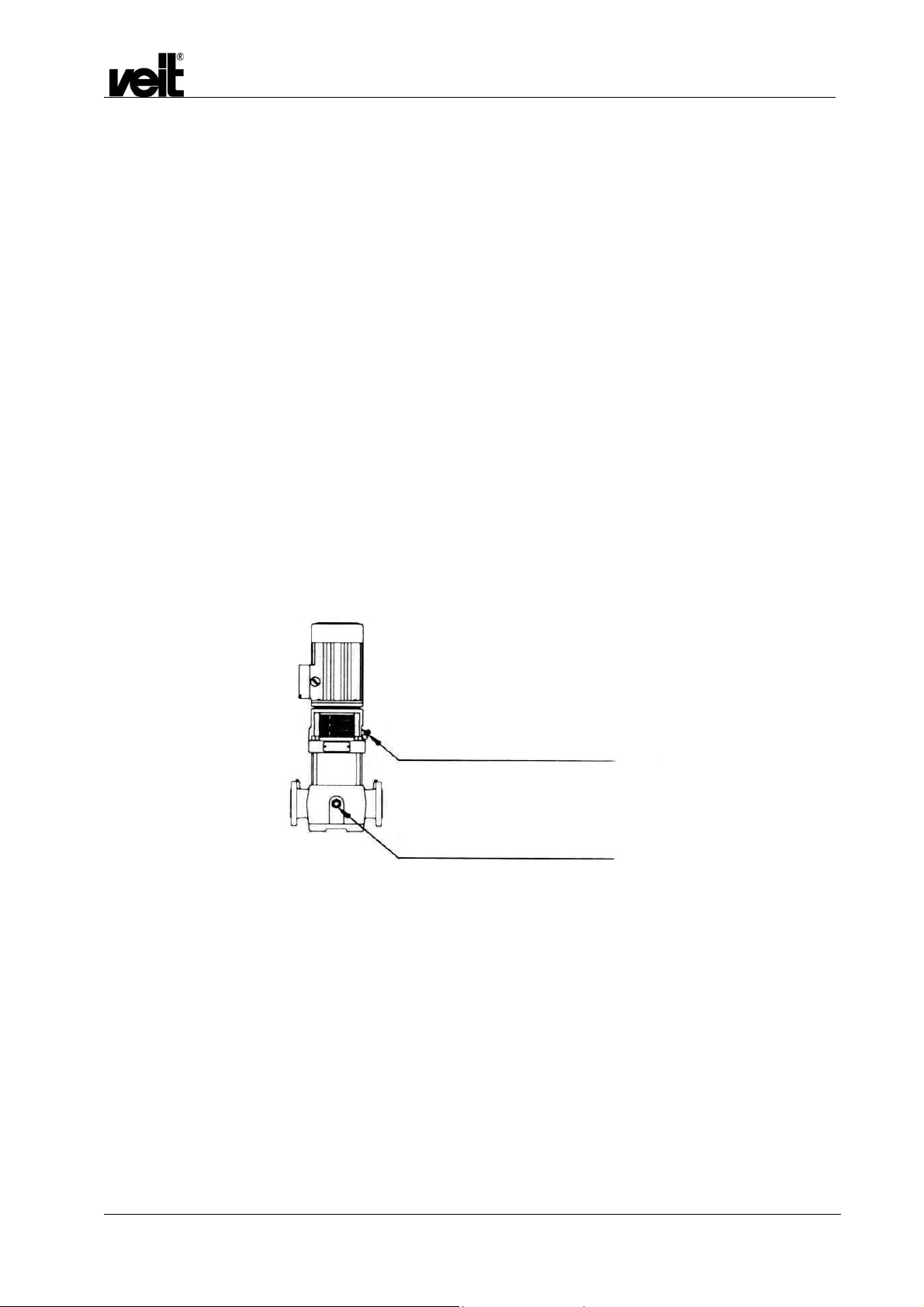
Vor der Inbetriebnahme muss die Pumpe unbedingt mit
dem Fördermedium aufgefüllt und entlüftet sein.
Das Absperrventil in der Saugleitung langsam öffnen, bis
das Medium aus der Entlüftungsöffnung heraus läuft.
Entlüftungsschraube anziehen und Absperrventil ganz
öffnen.
Vor dem Einschalten des Gerätes:
• Die Wasserhärte messen
• Den Kugelhahn vor dem Schwimmerventil sowie den
Kugelhahn zwischen Speisewassergefäß und Kessel öffnen.
Den Dampfhahn während der Befüllung (Pumpe läuft) offen
lassen. (Die Befüllung wird dadurch beschleunigt). Nach der
Befüllung schließen, um den Betriebsdruck schneller zu
erreichen.
Entlüftungsschraube / Einfüllstopfen
drain plug / circulation valve
Entleerungsstopfen / Umlaufventil
vent screw / feeding plug
Note the following before first using the boiler:
• Check the electrical connection. Test the direction of rotation
of the pump motor; if the direction of rotation is wrong,
change two phases.
• Fill the feed water tank.
• Attention! (Only for Steam Stations with special pump
[special production])
Before starting operation, the pump must be filled with
the pumping medium and air-vented.
Open the stop valve in the suction line slowly, until the
medium flows out of the vent hole.
Fasten the vent screw and open the stop valve completely.
Before switching on the unit:
• Measure the water hardness.
• Open the ball valve in front of the float valve and open the
ball valve, which is between the feed water tank and the
boiler.
Let the steam valve open during the filling (pump works). (in
order to fill faster). Close after filling to reach the operating
pressure more quickly.
31.01.2007 8

1.6.1 Betrieb / Operating
Hauptschalter einschalten.
Über den Wahlschalter die gewünschte Leistung einschalten.
Die Pumpe befüllt den Kessel. Sollte die Pumpe bei der
Inbetriebnahme kein Wasser fördern, muss sie entlüftet werden.
(Vierkantschraube neben dem Eingangsstutzen öffnen bis
Wasser kommt).
Bei Erreichung des NW werden die Heizungen eingeschaltet.
Der Dampfdruck wird am Manometer angezeigt. Wenn der
Betriebsdruck erreicht ist wird der Dampfhahn langsam geöffnet.
Der weitere Betrieb funktioniert automatisch.
Bei Betriebsende wird der Hauptschalter ausgeschaltet, der
Dampfhahn geschlossen und der Kessel abgeschlämmt. Zur
Abschlämmung wird der 3/4" Abschlämmhahn geöffnet; das
gesamte Kesselwasser mit den Kalkresten wird weggespült.
Wenn das Manometer keinen Druck mehr anzeigt, wird der
Abschlämmhahn geschlossen und der Kessel neu befüllt.
Danach wieder ausschalten und Wasserversorgung schließen.
Dampfstation VEIT 2380 12 kW / 26 kW / 39 kW / 52 kW
VEIT 2380 Steam Station 12 kW / 26 kW / 39 kW / 52 kW
Switch on the main switch.
Set the required power with the selection switch.
The pump fills the boiler. If the pump does not supply any water
when started, venting is necessary. (Open the square-head bolt
beside the inlet plinth until water comes.)
When the minimum water level is reached, the heating elements
are switched on. The steam pressure is indicated by the
pressure gauge. When the working pressure is reached, the
steam valve is opened slowly.
The next operating steps are automatic.
When the operation is finished, the main switch is switched off,
the steam valve is closed and the boiler is drained. For drainage
the 3/4" drainage valve is opened; all the boiler water with the
scale rests is removed.
When the manometer indicates no pressure, the drainage valve
is closed and the boiler is refilled. Switch off again and close the
water supply.
1.7 Prüf- und Wartungsarbeiten / Inspection and Maintenance Work
Täglich:
• Die Funktion des Manometers und Druckreglers überprüfen.
• Die Dichtheit aller Kugelhähne überprüfen.
• Kessel abschlämmen.
Wöchentlich:
• Speisewasserbehälter ablassen und anschließend mit
frischem Wasser befüllen.
• Schmutzfänger in der Pumpenzulaufleitung sowie ggf.
Feinfilter vor der Enthärtungsanlage reinigen.
• 1-2 mal jährlich muss die Funktion des Sicherheitsventils
durch Anlüften geprüft werden.
Jährlich:
• Alle Anschlüsse (Elektro, Frischwasser, Überläufe,
Kondensat, Dampf) auf Dichtheit, Korrosion und Festigkeit
kontrollieren. Alle Kabelklemmen am Hauptschalter an den
Sicherungen und Heizungsschützen nachziehen.
• Zur Wartung des Kessels Flanschdeckel abnehmen. Das
Innere des Kessels, die Elektroden und die Heizungen von
Schmutz und Kalkablagerungen reinigen.
• Das Schutzrohr der Elektrode auf Kalkablagerungen
kontrollieren, gegebenenfalls reinigen. Dazu in den Kessel
leuchten und durch die Öffnung für die Elektrode den
Zustand des Schutzrohrs prüfen.
• Befüll- und Abschlämmstutzen auf Kalkreste kontrollieren
und ggf. reinigen.
• Bei der Montage des Flanschdeckels muss eine neue
Dichtung verwendet werden.
• Alle Funktionsteile (Manometer, Druckregler,
Sicherheitsventil, Wasserventil, Rückschlagventil, etc.) auf
eine einwandfreie Funktion prüfen.
31.01.2007 9
Daily:
• Inspect the function of the manometer and the pressure
regulator.
• Check all ball valves for leakage.
• Drain the boiler.
Weekly:
• Empty the feed water tank and fill with fresh water.
• Clean the dirt trap of the suction pipe of the pump and, if
necessary, clean the fine filter in front of the water-softening
unit.
• Once or twice a year, the function of the safety valve must
be tested by venting.
Yearly:
• Check all the connections (electrical, fresh water, overflows,
condensate, steam) for leakage, corrosion and tightness.
Tighten all cable clamps at the main switch, fuses and
heating contactors.
• Remove the flange lid for maintaining the boiler. Remove dirt
and scale deposits from the inside of the boiler, the
electrodes and the heating elements.
• Check the protecting tube of the electrode for furring, if
necessary clean. To do so, shine with a lamp into the boiler
and check through the opening of the electrodes the
condition of the protecting tube.
• Inspect the filling and the drainage plinths for scale deposits
and clean, if necessary.
• A new seal must be used, when the flange lid is mounted.
• Check that all the function parts (manometer, pressure
regulator, safety valve, water valve, check valve, and so on)
work properly.

• Befüll- und Abschlämmleitung demontieren und reinigen,
korrodierte Teile erneuern.
• Dampfleitung demontieren und reinigen, korrodierte Teile
erneuern.
• Die Plunger in den Elektromagnetventilen (Befüllgruppe und
Kondensatleitung) auf Dichtheit prüfen, ggfs. erneuern.
• Bei Ausfall der Speisewasser-Temperatur-Anzeige ist die
Batterie (1,5 V Mignonbatterie) zu wechseln und die Anzeige
neu zu initialisieren, siehe Merkblatt 2380-002.
Dampfstation VEIT 2380 12 kW / 26 kW / 39 kW / 52 kW
VEIT 2380 Steam Station 12 kW / 26 kW / 39 kW / 52 kW
• Disassemble and clean the filling and drainage line. Replace
corroded parts.
• Disassemble and clean the steam line. Replace corroded
parts.
• Check the plungers in the solenoid valves (filling group and
condensate line) for leakage, if necessary replace.
• The battery (1.5 V Mignon battery) must be replaced if the
feed water temperature indicator does not work any more,
and then the indication must be initialised again, see
information leaflet 2380-002.
31.01.2007 10
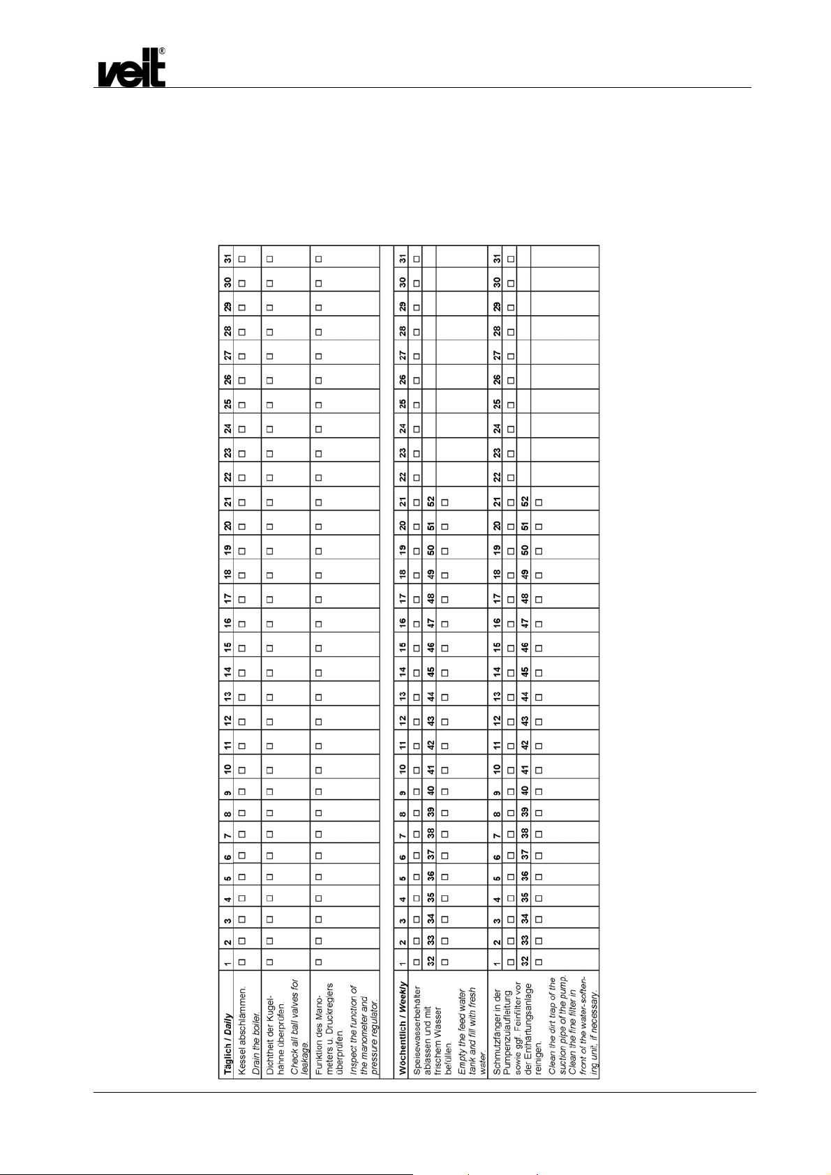
1.8 Wartungsplan / Maintenance Schedule
Dampfstation VEIT 2380 12 kW / 26 kW / 39 kW / 52 kW
VEIT 2380 Steam Station 12 kW / 26 kW / 39 kW / 52 kW
Bitte beachten Sie Kapitel 1.7 der Betriebsanleitung.
Als Fotokopiervorlage für das ganze Jahr verwenden, bei
Erledigung abhaken ;.
Monat / Jahr ..................
Please read section 1.7 of the operating instructions.
Copy and use as schedule for each year. Fill out after
maintaining
Month / Year .................
;
.
31.01.2007 11

Dampfstation VEIT 2380 12 kW / 26 kW / 39 kW / 52 kW
VEIT 2380 Steam Station 12 kW / 26 kW / 39 kW / 52 kW
31.01.2007 12

2 Ersatzteile / Spare Parts
2.1 Zeichnungen / Drawings
Zeichnung 1 / Drawing 1
34
Dampfstation VEIT 2380 12 kW / 26 kW / 39 kW / 52 kW
VEIT 2380 Steam Station 12 kW / 26 kW / 39 kW / 52 kW
35
31.01.2007 13

Zeichnung 2 / Drawing 2
Dampfstation VEIT 2380 12 kW / 26 kW / 39 kW / 52 kW
VEIT 2380 Steam Station 12 kW / 26 kW / 39 kW / 52 kW
31.01.2007 14

Dampfstation VEIT 2380 12 kW / 26 kW / 39 kW / 52 kW
Zeichnung 3 / Drawing 3
Bei Geräten mit Sonderpumpe (Sonderanfertigung) / For Steam Station with special pump (special production)
VEIT 2380 Steam Station 12 kW / 26 kW / 39 kW / 52 kW
31.01.2007 15

2.2 Ersatzteilliste / Spare Parts List
Dampfstation VEIT 2380 12 kW / 26 kW / 39 kW / 52 kW
VEIT 2380 Steam Station 12 kW / 26 kW / 39 kW / 52 kW
Pos. Artikelnummer
Article Number
* 123 801 005 0 Dampfstation 2380 12 kW / 400 V / 50 Hz
* 123 801 000 0 Dampfstation 2380 39 kW / 400 V / 50Hz
* 123 801 001 0 Dampfstation 2380 26 kW / 400 V / 50 Hz
* 123 801 002 0 Dampfstation 2380 52 kW / 400 V / 50 Hz
** 123 803 003 0 Dampfstation 2380 36 kW/ 3x220 V/ 60 Hz
*** 123 803 001 0 Dampfstation 2380 48 kW/ 3x220 V/ 50 Hz
*** 123 803 002 0 Dampfstation 2380 39 kW/ 3x200 V/ 50 Hz
* 123 801 003 0
(Sonderanfertigung)
(special production)
* 123 801 004 0
(Sonderanfertigung)
(special production)
01 423 038 003 0 Schwimmerventil mit
02 425 217 003 0 Pumpe TP 80 380 V / Bronze –
02a 425 217 005 0 Dichtungssatz für TP 80 - Pumpe
02b 425 217 009 0 Laufrad für TP 80 - Pumpe
02 423 808 000 0 Pumpe CR2 für Geräte mit
03 929 065 053 0 EMV NW 4 230 V / 50-60 Hz
428 321 000 0 Spule 200-254 V/ 50-60 Hz / EMV
04 483 622 023 0 Rückschlagventil 1/2“ kpl. montiert
927 012 011 0 Kupferring 22x28x2 mit Füllung
05 423 801 025 0 Elektrode L = 465 mm weiß
06 423 801 071 0 Elektrode L = 345 mm schwarz
07 423 802 033 0 Heizung 13 kW mit Dichtung
07 425 215 002 G Heizung mit Dichtung 6 kW
219 000 033 0 Rohrsteckschlüssel SW 55/60 für
09 929 065 045 0 Manometer 0-16 bar
10 423 803 003 0 Druckwächter 0,5-8 bar
11 929 065 044 0 Sicherheitstemperatur-Begrenzer
12 423 801 048 0 Dichtung / Kesselflansch
13 929 075 069 0 Leistungsschütz 230 V / 50-60 Hz /
929 075 105 0 Leistungsschütz 220 V / 50 Hz
Bezeichnung Designation
Dampfstation 2380 39 kW/ 400 V/50 Hz mit
Sonderpumpe (Sonderanfertigung)
Dampfstation 2380 52 kW/ 400 V/50 Hz mit
Sonderpumpe (Sonderanfertigung)
Schwimmerkugel
Ausführung
Sonderpumpe (nur bei
Sonderanfertigung)
NW 2,8-4
Heizung
55.325
7,5 kW für Dampfstation mit *)
DIL1AM für Dampfstationen mit **)
und ***)
float valve with float ball
pump TP 80 380V/bronze version
seals set for TP 80 – pump
wheel for TP 80 – pump
pump CR2 for units with special pump
(only at special production)
solenoid valve nominal value 4
230 V / 50-60 Hz
coil 200-254V/50-60Hz / solenoid
valve nominal value 2.8-4
check valve 1/2" cpl. assembled
copper ring 22x28x2 with filling
electrode length 465mm white
electrode length 345 mm black
heating element 13kW with seal
heating element 6 kW with seal
tubular hexagon box spanner SW
55/60 for heating element
manometer 0-16 bar
pressure control 0.5-8 bar
safety temperature limiter 55.325
seal / boiler flange
power contactor 230V/50-60 Hz 7.5
kW for steam stations with *)
power contactor 220V/50Hz DIL1AM
for steam stations with **) and ***)
steam station 2380 12 kW / 400V/50Hz
steam station 2380 39 kW / 400V/50Hz
steam station 2380 26 kW / 400V/50Hz
steam station 2380 52 kW / 400V/50Hz
steam station 2380 36 kW / 3x220V/60Hz
steam station 2380 48 kW / 3x220V/50Hz
steam station 2380 39 kW / 3x200V/50Hz
steam station 2380 39 kW / 400 V / 50 Hz
with special pump (special production)
steam station 2380 52 kW / 400 V / 50 Hz
with special pump (special production)
M1
M1
Y1; Y4
B1
B2
R1-4
N1
FT2
K1-3,5
K1-3,5
31.01.2007 16

Dampfstation VEIT 2380 12 kW / 26 kW / 39 kW / 52 kW
14 423 055 007 0 Leistungsschütz 220 V / 50-60 Hz
15 423 801 051 0 Temperatur-Messmodul bearbeitet
17 425 235 003 0 Motorschutzrelais 2,4-4A
18 443 045 001 0 Kontroll-Lampe rot
19 443 045 002 0 Kontroll-Lampe weiß
20 929 075 097 0 Signalleuchte rot mit LED
21 929 075 098 0 Signalleuchte grün mit LED
22 929 075 099 0 Signalleuchte gelb mit LED
23 423 315 001 0 Schalter doppelt
24 928 015 181 0 Lampe T 4,5 / Leucht-Drucktaster
25 929 075 080 0 Signalgeber Piezzo elektrisch
26 929 075 083 0 Schmelzeinsatz 25 A für
Dampfstation mit *) **)
929 075 129 0 Schmelzeinsatz 35 A für
Dampfstation ***)
27 929 075 087 0 Schmelzeinsatz 6 A
28 929 075 091 0 Schmelzeinsatz 4 A
29 423 805 000 0 Hauptschalter P3-100 / EA / SVB SW
für Dampfstation mit *) und **)
928 015 177 0 Hauptschalter 125A T6-2 / EA / SVB
für Dampfstation mit ***)
30 423 805 005 0 Steuerungsplatine Version IV / 2380
31 423 805 002 0 Thermostat 60°C
31 423 805 006 0 Thermostat 80°C für Geräte mit
Sonderpumpe
33 425 213 004 Y Sicherheitsventil 7 bar
34 929 065 103 0 EMV NW 6 230V / 50-60 Hz
428 321 000 0 Spule 200-254 V / 50-60 Hz / EMV
NW 2,8-4
35 929 015 027 0 Kugelhahn R ¾“ (Abschlämmen)
ACHTUNG!
Der Durchfluss der zwei Wasserventile muss immer in
entgegengesetzter Richtung sein!
(zu Pos. 3 und Pos. 34 der Ersatzteilliste)
VEIT 2380 Steam Station 12 kW / 26 kW / 39 kW / 52 kW
Attention!!
The flow of the two water valves must always be in an opposite
direction!
(to pos. 3 and pos. 34 of the spare parts list)
power contactor 220V/50-60 Hz
temperature-measuring module
motor protection relay 2.4-4A
control lamp red
control lamp white
signal lamp red with LED
signal lamp green with LED
signal lamp yellow with LED
switch double
lamp T 4,5/illuminated push button
signal transmitter Piezzo electr.
fusible plug 25A
fusible plug 35A for steam stations
with ***)
fusible plug 6A
fusible plug 4A
main switch P3-100 / EA / SVB SW
for steam stations with *) and **)
main switch 125A T6-2/EA/SVB for
steam stations with ***)
control PC-board version IV / 2380
thermostat 60°C
thermostat 80°C for units with special
pump
safety valve 7 bar
Solenoid valve nominal value 6
230 V / 50-60 Hz
Coil 200-254 V / 50-60 Hz / solenoid
valve nominal value 2.8-4
Ball cock valve R ¾” (drain)
K4
A2
FT1
H1
H2
LED1
LED2
LED3
S1+S2
S3
H6
F1 bis F9
F10 bis F12
F13
Q1
Q1
A1
N2
N2
Y2; Y3
31.01.2007 17

Dampfstation VEIT 2380 12 kW / 26 kW / 39 kW / 52 kW
VEIT 2380 Steam Station 12 kW / 26 kW / 39 kW / 52 kW
3 Zeichnung der Anschlüsse / Drawing of the Connections
(zu Punkt 1.4 der Betriebsanleitung) / (To section 1.4 of the operating instructions)
- Dampfanschluss R1/2 innen
- Kondensatanschluss R1/2 innen
- Speisewasseranschluss und Entleerung
Speisewasserbehälter
- Überlauf Abschlämmbehälter Schlauchtülle für
Schlauch ¾ (9270530460)
- Absaugschlauch für Entleerung 2497700840,
Schlauchklemme 9230110320
- Steam connection R1/2 inside
- Condensate connection R1/2 inside
- Feed water and emptying of feed water tank
- Overflow blow-down tank hose nozzle for hose ¾
(9270530460)
- Suction hose for air-vent 2497700840, hose clamp
9230110320
31.01.2007 18

4 Merkblatt / Information Leaflet 2380-001
Achtung: Wichtiger Hinweis für den Austausch der
Steuerplatine bei Geräten bis Baujahr
8/1997
1. Am Stecker CN1 muss zwischen die Anschlüsse 9 und 10
eine Brücke geklemmt werden, siehe Skizze.
2. Überprüfen Sie die Netzspannungseinstellung.
3. Der Schiebeschalter S1 stellt die Pumpenüberwachungszeit
ein. In der Regel ist die Mittelstellung (4 Minuten
Nachlaufzeit) die richtige Einstellung.
4. Die Potentiometer P1 und P2 sind voreingestellt und
brauchen in der Regel nicht verändert zu werden.
Dampfstation VEIT 2380 12 kW / 26 kW / 39 kW / 52 kW
VEIT 2380 Steam Station 12 kW / 26 kW / 39 kW / 52 kW
Attention: Important information to replace the PC-board for
units up to date of fabrication 8/1997:
1. At the plug CN1 a bridge must be clamped between the
connections 9 and 10, see drawing.
2. Check the adjustment of supply voltage.
3. By means of the slide switch S1 the control time of the
pump is adjusted. Normally the central position (run-out
time of 4 minutes) is the correct adjustment.
4. The potentiometer P1 and P2 are set by the factory and
don't have to be changed.
31.01.2007 19
Dampfstation VEIT 2380 12 kW / 26 kW / 39 kW / 52 kW
VEIT 2380 Steam Station 12 kW / 26 kW / 39 kW / 52 kW
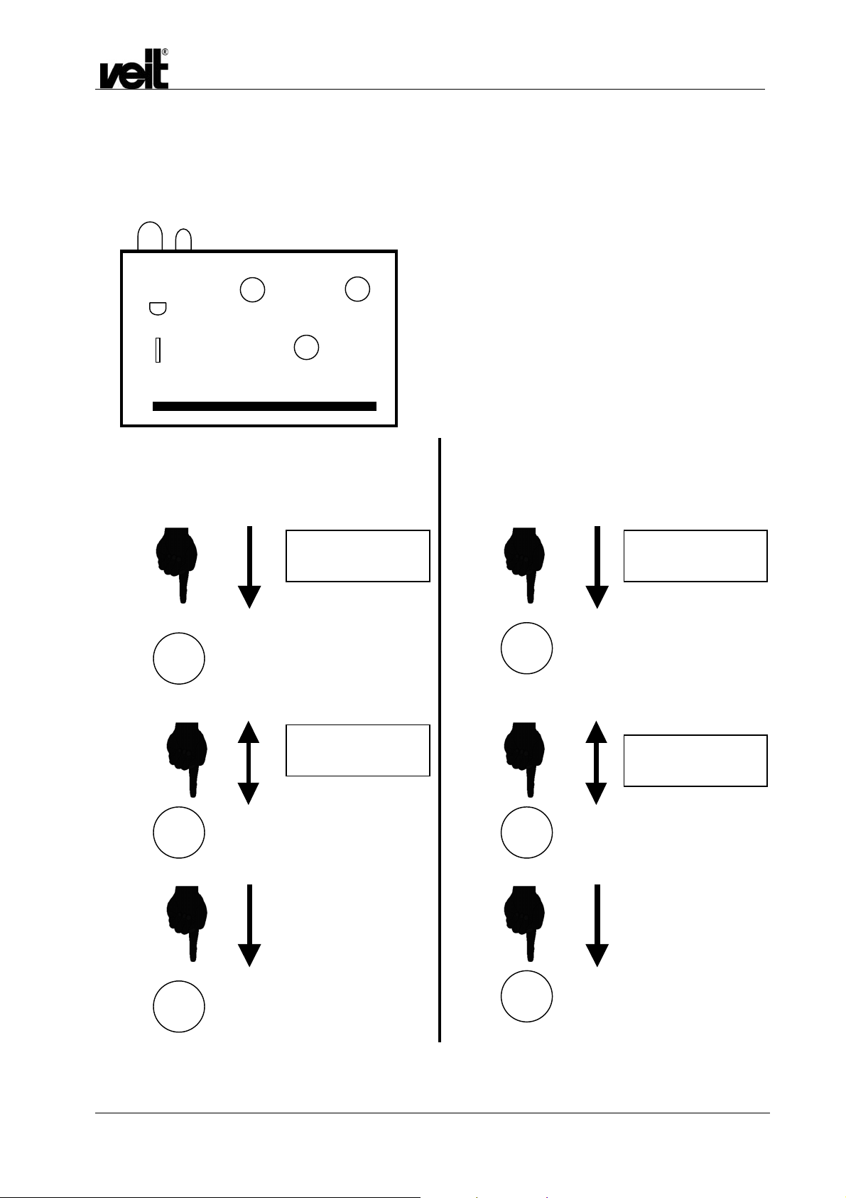
5 Merkblatt / Information Leaflet 2380-002
Programmieranweisung Temperaturmessmodul /
Programming Instructions Temperature measure module
I III
II
Programmierung MAX
Programming MAX
II
I
MAX
- - - - °C
MAX
70.0°C
(90°C)
Programmierung MIN
Programming MIN
III
I
MIN
- - - - °C
MIN
5.0°C
II
III
31.01.2007 20

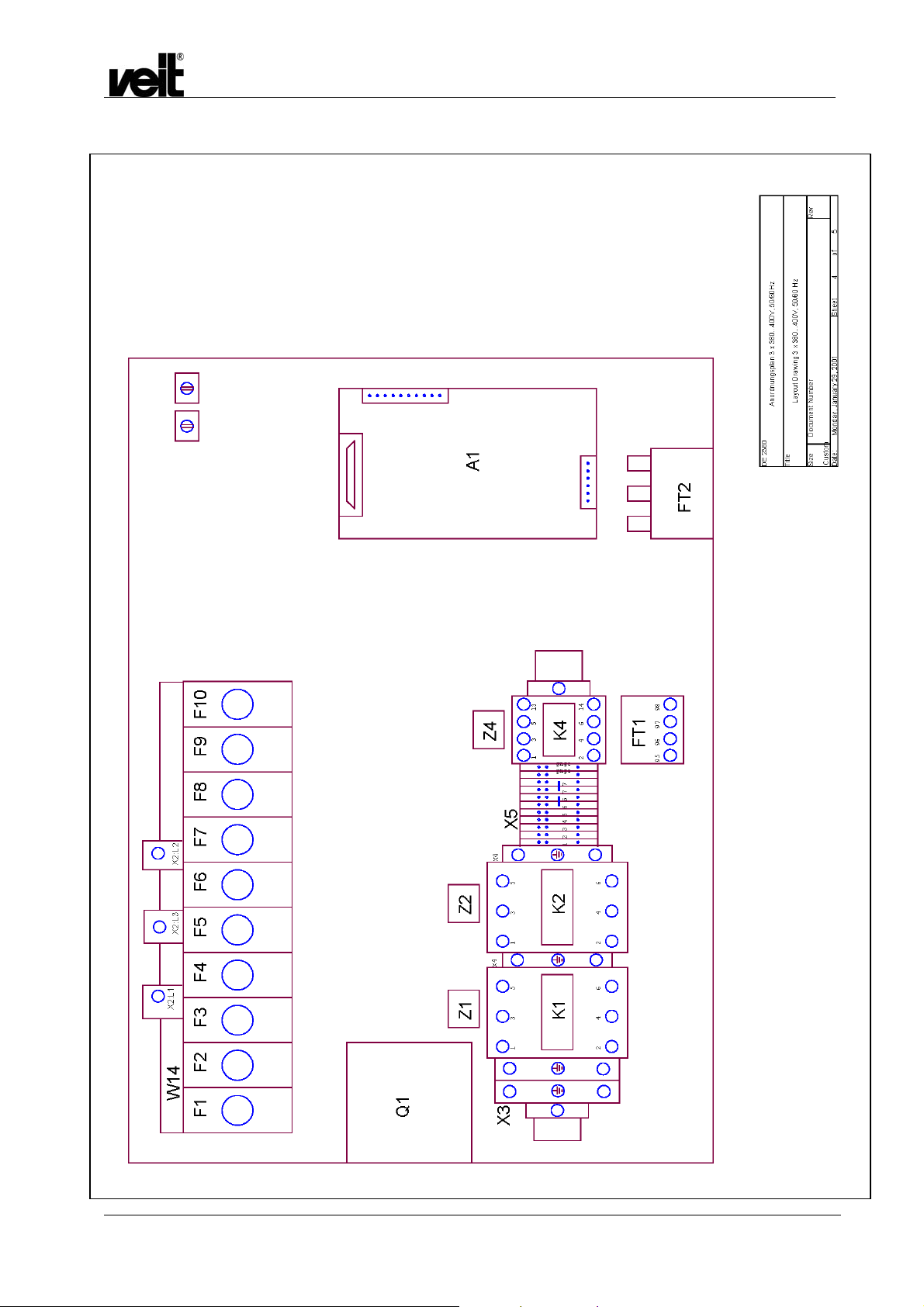
6 Schaltpläne / Circuit Diagrams
6.1 12 kW / 400 V, 50 Hz
Dampfstation VEIT 2380 12 kW / 26 kW / 39 kW / 52 kW
VEIT 2380 Steam Station 12 kW / 26 kW / 39 kW / 52 kW
31.01.2007 21

12 kW / 400 V, 50 Hz
Dampfstation VEIT 2380 12 kW / 26 kW / 39 kW / 52 kW
VEIT 2380 Steam Station 12 kW / 26 kW / 39 kW / 52 kW
31.01.2007 22

12 kW / 400 V, 50 Hz
Frontplatte
front panel
Batteriewechsel und Einstellungen
am Temperaturmessmodul.
- Dampferzeuger ausschalten
- Haltewinkel entfernen
- Batterie entfernen
- Neue Batterie einlegen
- Haltewinkel anbringen
- Taster S2 1 x betaetigen
- Taster S1 druecken, bis 75C
in Display erscheint
- Taster S2 erneut betaetigen
- Taster S3 1 x betaetigen
- Taster S1 druecken, bis 5C
im Display erscheint
- Taster S3 erneut betaetigen
Dampfstation VEIT 2380 12 kW / 26 kW / 39 kW / 52 kW
VEIT 2380 Steam Station 12 kW / 26 kW / 39 kW / 52 kW
max. norm. zu niedrig
R1
4
5
6
+
-
H7
H5
S1 S2 S3
7
8
9
10
11
H4
12
13
343
pressure
overflow
14
15
4
X2
1
2
16
17
H9
Maximaldruck
Ueberschreitung
Q1
X1
A2
1
2
3
max
min
Behaelter leer tank empty
Zuruecksetzen
reset
battery exchange and adjustment
of the temperature measuring instrument
- turn off the steam generator
- remove the fastening part of the
temperature measuring instrument
- remove the battery
- insert a new battery
- mount the fastening part
- push the key S2 one time
- push the key S1, until on the
display occures 75C
- push the key S2 one time again
- push the key S3 one time
- push the key S1, until on the
display occures 5C
- push the key S3 one time again
Speisewasser
Temperatur
water supply
temperature
W13
CN3.1
too low
H8
+
H6
-
wsge
rtbl
bngn
13
25
12
24
11
grrosswwsgnwsrosgrvioblgn
23
10
22
21
20
19
9
8
7
6
18
5
gebngert
17
16
4
3
bn
15
14
2
1
DE 2380
Title
Size Document Number Rev
Custom
Date: Sheet
Dampferzeuger 2380 12kW/400V/40-60Hz
Steam Boiler 2380 12kW/400V/40-60Hz
35Monday, January 29, 2001
of
31.01.2007 23
12 kW / 400 V, 50 Hz
Dampfstation VEIT 2380 12 kW / 26 kW / 39 kW / 52 kW
VEIT 2380 Steam Station 12 kW / 26 kW / 39 kW / 52 kW
31.01.2007 24
12 kW / 400 V, 50 Hz
Dampfstation VEIT 2380 12 kW / 26 kW / 39 kW / 52 kW
VEIT 2380 Steam Station 12 kW / 26 kW / 39 kW / 52 kW
Speisewasser-Temperaturbegrenzung
Temperature limiting of feedwater
U_st_L1
U_st_N
76
X5
N2
PE
1
24
PE
W16
A1
Y3
A2
Speisewasserbehälter
condensate to the
feedwater tank
DE 2380
Size Document Number Rev
Date: Sheet
W15
Speisewasser-Temperaturbegrenzung
380...400V, 50/60 Hz
Temperature limiting of feedwater
380...400 V, 50/60 Hz
A1
Y2
A2
Kondensat zum AbflussKondensat zum
condensate to
the outlet
of
55Monday, January 29, 2001
31.01.2007 25
6.2 26 kW / 400 V, 50 Hz
Dampfstation VEIT 2380 12 kW / 26 kW / 39 kW / 52 kW
VEIT 2380 Steam Station 12 kW / 26 kW / 39 kW / 52 kW
31.01.2007 26

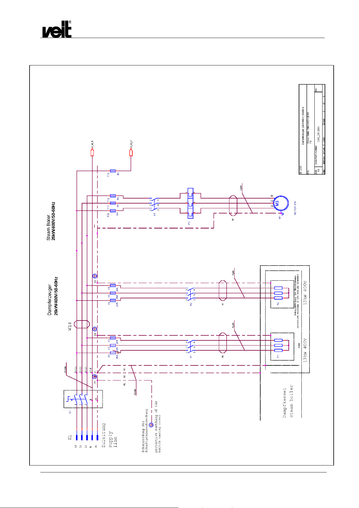
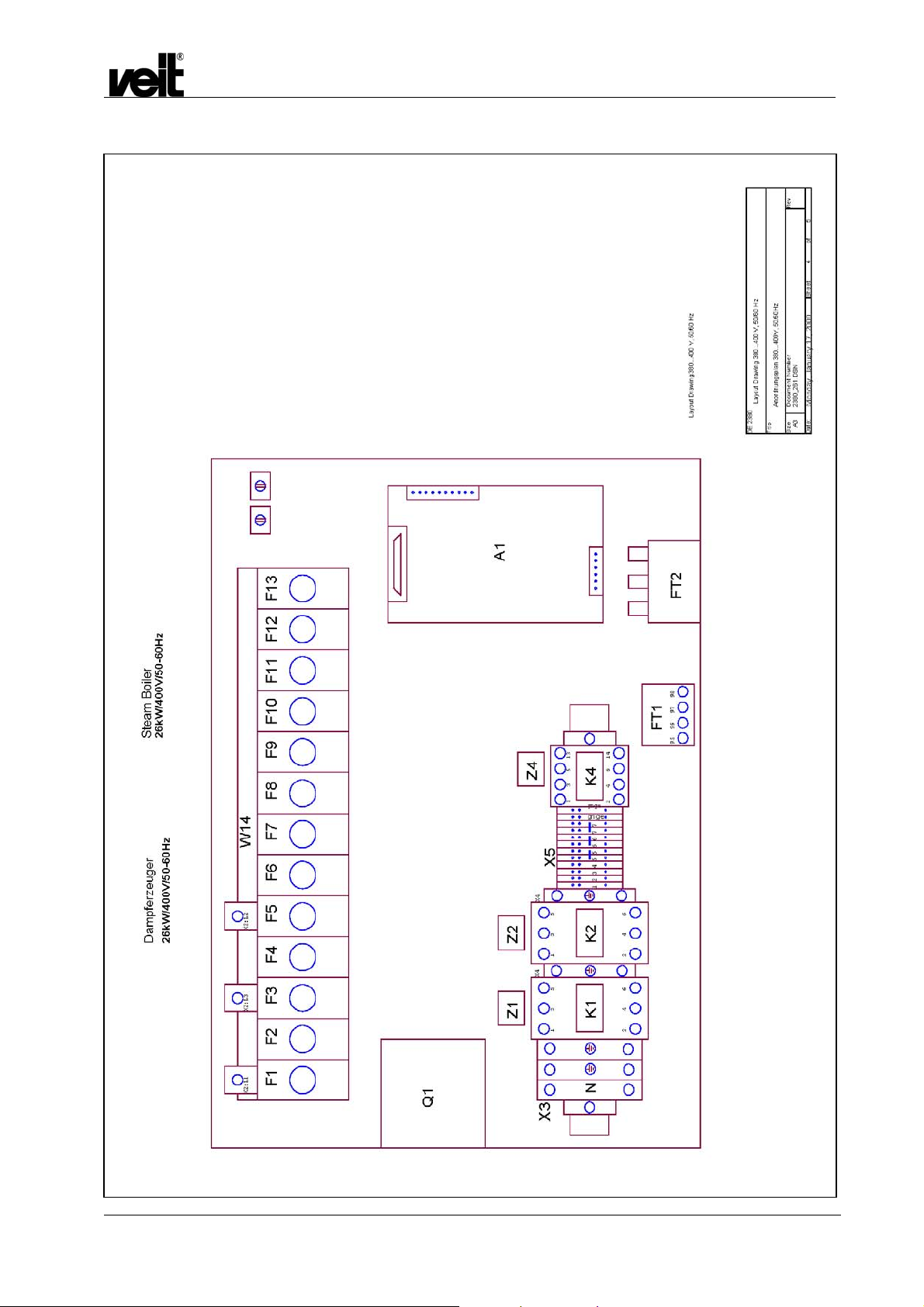
26 kW / 400 V, 50 Hz
Dampfstation VEIT 2380 12 kW / 26 kW / 39 kW / 52 kW
VEIT 2380 Steam Station 12 kW / 26 kW / 39 kW / 52 kW
31.01.2007 27

z
0
m
3
5
0
e
t
343
4
+
-
g
w
+
-
k
g
e
w
A2
y
n
t
3
w
i
lgn
ertbnS1S2S3
nmax
n
n
t
t
t
t
t
t
z
r
r
5
9
5
3
0
9
8
0
7
9
6
8
5
4
6
3
5
2
4
2
2
2345678
9
0
3
4
5
6
7
26 kW / 400 V, 50 Hz
Dampfstation VEIT 2380 12 kW / 26 kW / 39 kW / 52 kW
VEIT 2380 Steam Station 12 kW / 26 kW / 39 kW / 52 kW
Dam pferzeuge
26kW/400V/50-60Hz
max. norm. zu niedri
H
H7
Steam Boile
26kW/400V/50-60Hz
too lo
H8
Frontplatte
front panel
Maximaldruc
Ueberschreitun
Q1
R1
X1
1
mi
Behaelter leer tank empt
Zuruecksetze
rese
pressur
H
overflo
X
1
1
1
1
1
1
12
11
1
H4
Speisewasser
Temperatur
water supply
temperature
H6
W1
s
ws
Batt eriewechsel und Einstellungen
emperaturmessmodul.am T
Batteriewechsel und
Einstellungen am
-
Dampferzeuger ausschalten
Temperaturmessmodul.
-- Haltewinkel entfernen
- Dampferzeuger ausschalten
Batterie entferne
- Haltewinkel entfernen
- Neue Batterie einlege
- Batterie entfernen
-
Haltewinkel anbringen
- Neue Batterie einlegen
-
Taster S2 1 x betaetigen
- Haltewinkel anbringen
- Taster S2 1x betätigen
-
Taster S1 druecken, bis 75C
in Display erschein
- Taster S1 drücken, bis 75°C im
-
Taster S2 erneut betaetigen
Display erscheint
- Taster S2 erneut betätigen
-
Taster S3 1 x betaetigen
- Taster S3 1x betätigen
-
Taster S1 druecken, bis 5C
im Display erschein
- Taster S1 drücken, bis 5°C im
-
Taster S3 erneut betaetigen
Display erscheint
- Taster S3 erneut betätigen
battery exchange and adjustmen
of the temperature measuring instrumen
- turn off the steam generator
- remove the fastening part of the
temperature measuring instrumen
- remove the battery
- insert a new battery
- mount the fastening par
- push the key S2 one time
- push the key S1, until on the
display occures 75C
- push the key S2 one time again
- push the key S3 one time
- push the key S1, until on the
display occures 5C
- push the key S3 one time again
wsgertblbngngr
CN3.1
24
12
2
13
gr
ws
ro
v
gn
s
o
ro
s
1
2
21
22
1
2
11
g
b
ge
bn
1
1
1
17
1
1
Control Circuit 380...400 V, 50/60 H
DE 238
Titl
Steuerstromkreise 380...400V, 50/60H
SizeDoc ument Numb er Rev
Custo
Date: Shee
Monday, January 17, 200
Dampferzeuger 26kW/400V/50-60Hz
Steam Boiler 26kW/400V/50-60Hz
DE2380_261.DSN
of
31.01.2007 28
26 kW / 400 V, 50 Hz
Dampfstation VEIT 2380 12 kW / 26 kW / 39 kW / 52 kW
VEIT 2380 Steam Station 12 kW / 26 kW / 39 kW / 52 kW
31.01.2007 29
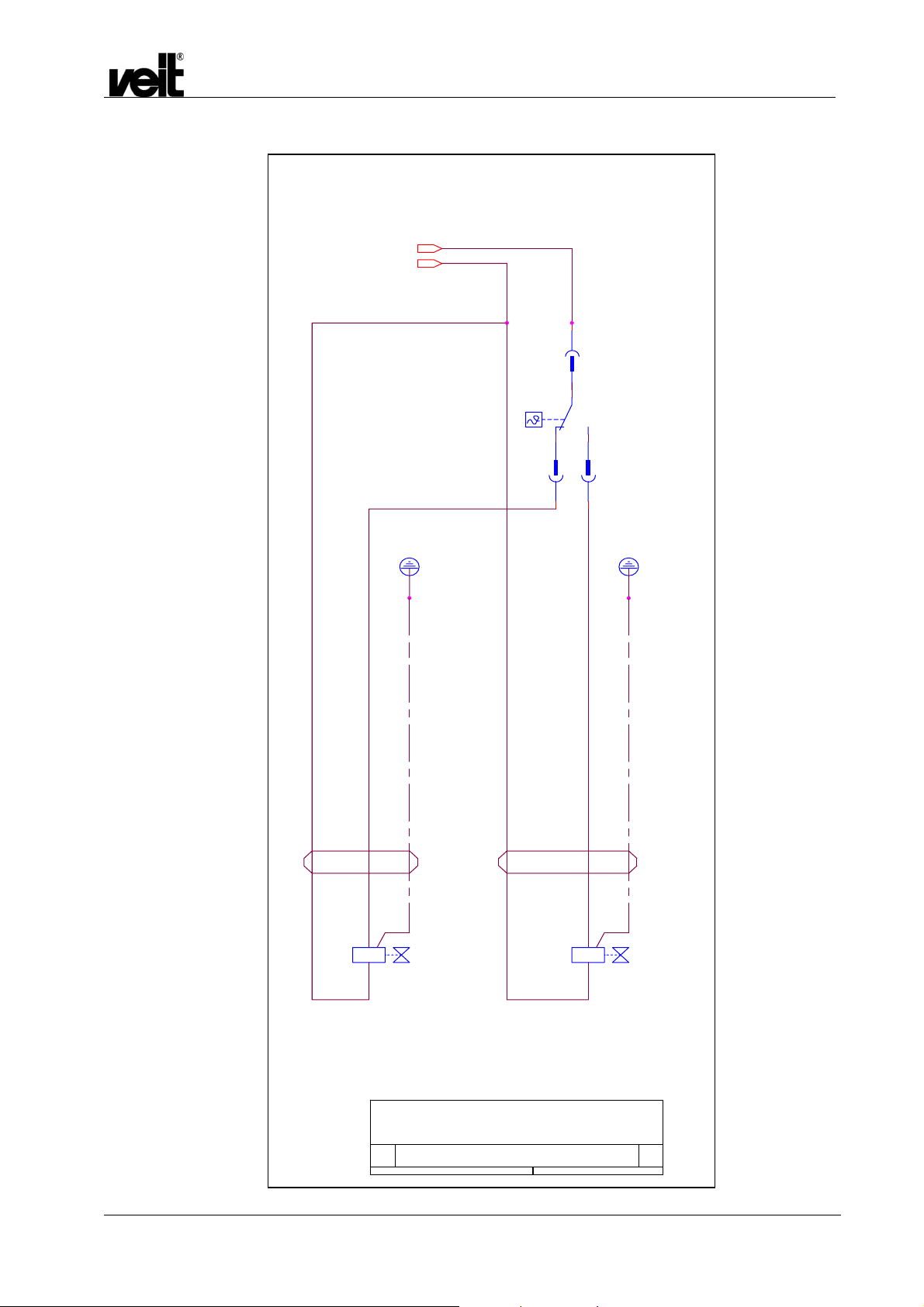
26 kW / 400 V, 50 Hz
Dampferzeuger
26kW/400V/50-60Hz
U_st_L1
U_st_N
76
X5
Steam Boiler
26kW/400V/50-60Hz
Dampfstation VEIT 2380 12 kW / 26 kW / 39 kW / 52 kW
VEIT 2380 Steam Station 12 kW / 26 kW / 39 kW / 52 kW
1
N2
24
PE
W16
W15
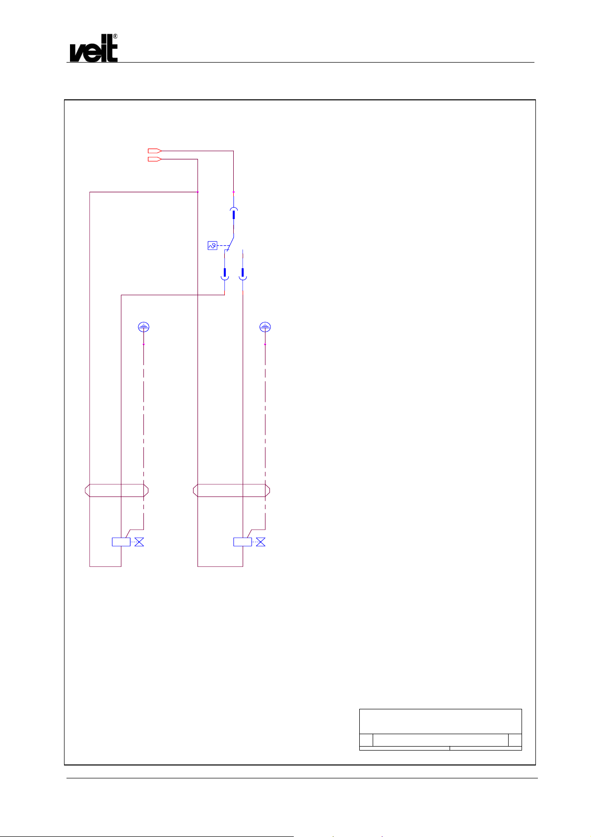
Speisewasser-Temperaturbegrenzung
Temperature limiting of feedwater
PE
A1
Y3
A2
Speisewasserbehälter
condensate to the
feedwater tank
A1
Y2
A2
Kondensat zum AbflussKondensat zum
condensate to
the outlet
DE 2380
Speisewasser-Temperaturbegrenzung
380...400V, 50/60 Hz
Size Document Number Rev
Custom
Date: Sheet
Temperature limiting of feedwater
380...400 V, 50/60 Hz
2380_261.DSN
of
55Monday, January 17, 2000
31.01.2007 30
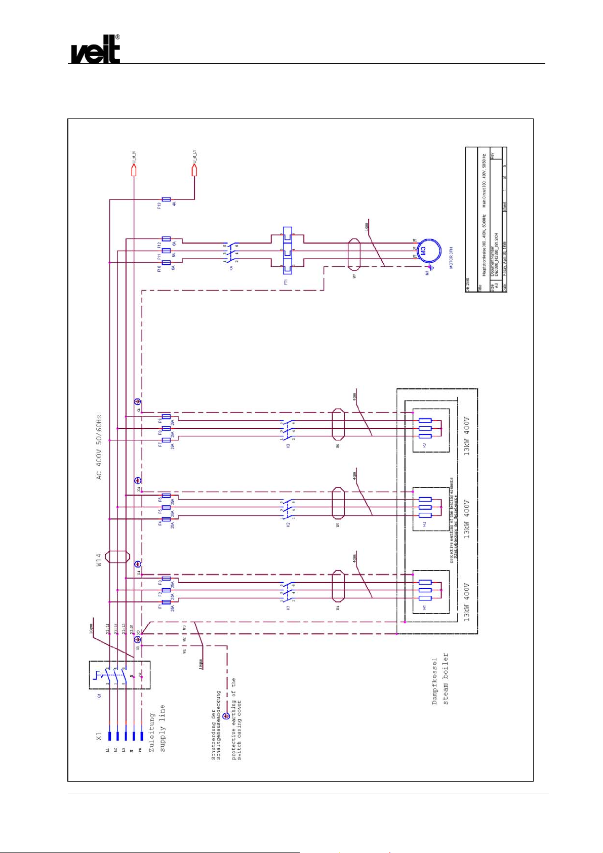
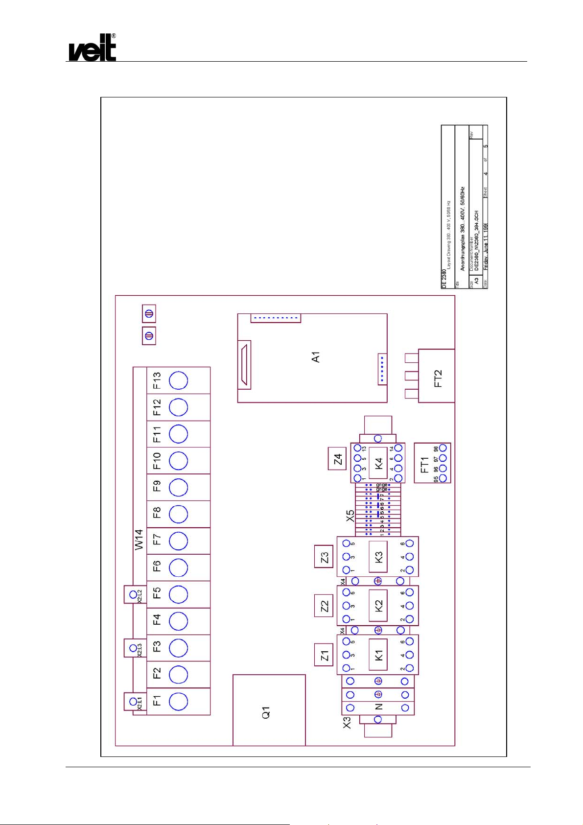
6.3 39 kW / 400 V, 50 Hz
Dampfstation VEIT 2380 12 kW / 26 kW / 39 kW / 52 kW
VEIT 2380 Steam Station 12 kW / 26 kW / 39 kW / 52 kW
31.01.2007 31

39 kW / 400 V, 50 Hz
Dampfstation VEIT 2380 12 kW / 26 kW / 39 kW / 52 kW
VEIT 2380 Steam Station 12 kW / 26 kW / 39 kW / 52 kW
31.01.2007 32

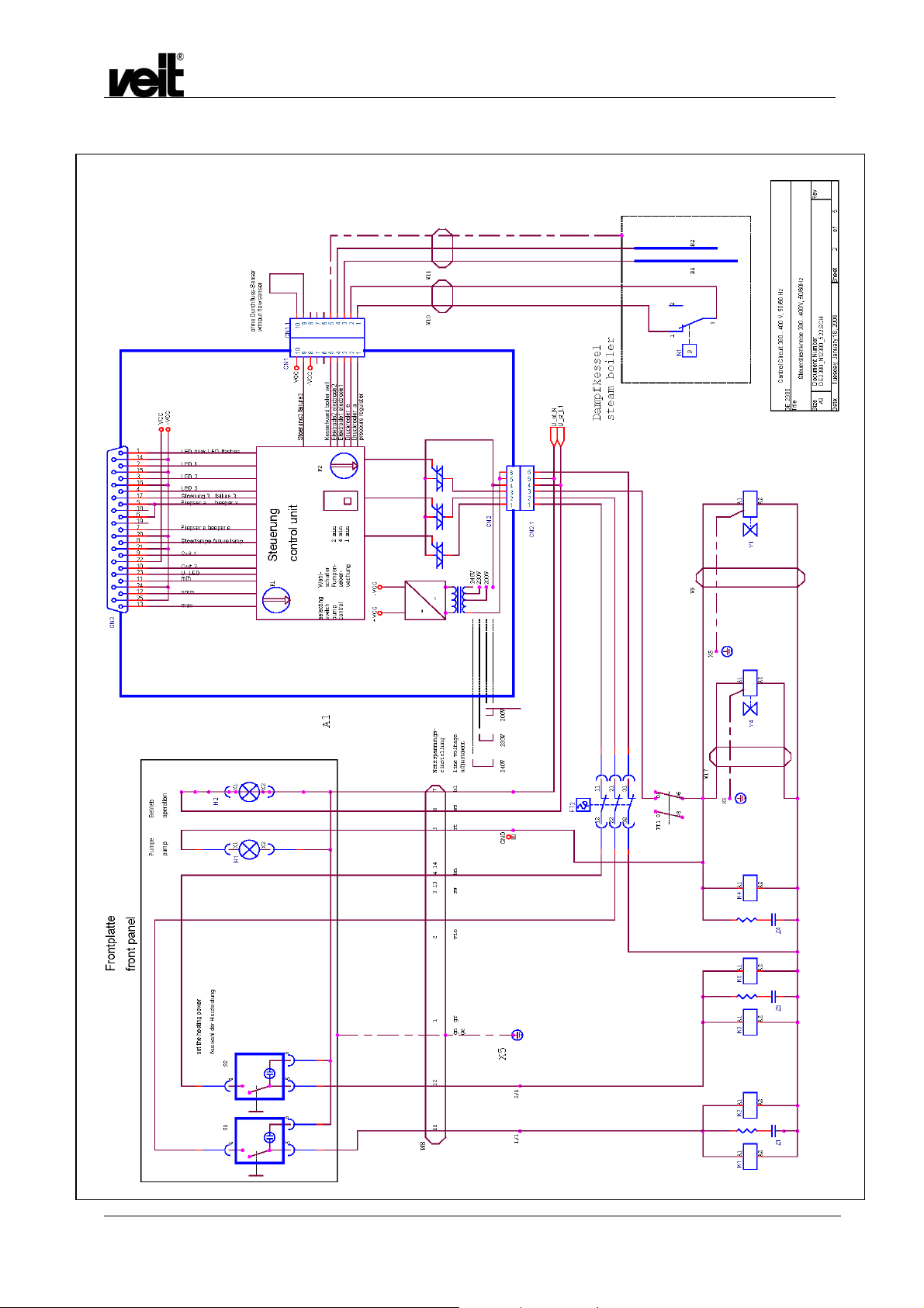
39 kW / 400 V, 50 Hz
Batteriewechsel und Einstellungen
am Temperaturmessmodul.
- Dampferzeuger ausschalten
- Haltewinkel entfernen
- Batterie entfernen
- Neue Batterie einlegen
- Haltewinkel anbringen
- Taster S2 1 x betaetigen
- Taster S1 druecken, bis 75C
in Display erscheint
- Taster S2 erneut betaetigen
- Taster S3 1 x betaetigen
- Taster S1 druecken, bis 5C
im Display erscheint
- Taster S3 erneut betaetigen
Dampfstation VEIT 2380 12 kW / 26 kW / 39 kW / 52 kW
VEIT 2380 Steam Station 12 kW / 26 kW / 39 kW / 52 kW
Frontplatte
front panel
max. norm. zu niedrig
H9
Maximaldruck
Ueberschreitung
Q1
R1
A2
Zuruecksetzen
reset
battery exchange and adjustment
of the temperature measuring instrument
- turn off the steam generator
- remove the fastening part of the
- remove the battery
- insert a new battery
- mount the fastening part
- push the key S2 one time
- push the key S1, until on the
- push the key S2 one time again
- push the key S3 one time
- push the key S1, until on the
- push the key S3 one time again
X1
3
2
1
max
min
Behaelter leer tank empty
temperature measuring instrument
display occures 75C
display occures 5C
S1 S2 S3
7
6
5
4
+
-
H7
pressure
H5
overflow
X2
1
2
17
16
15
14
13
12
11
10
9
8
H4
343
4
CN3.1
Speisewasser
Temperatur
water supply
temperature
H6
W13
13
too low
H8
+
-
wsge
rtbl
bngn
grrosswwsgnwsrosgrvioblgn
23
11
24
12
25
gebngert
17
18
19
20
21
22
10
9
5
6
7
8
bn
14
15
16
1
2
3
4
31.01.2007
DE 2380
Control Circuit 380...400 V, 50/60 Hz
Title
Steuerstromkreise 380...400V, 50/60Hz
Size Document Number Rev
DE2380_N\2380_393.SCH
A2
Date: Sheet
of
35Friday, April 30, 1999
33
39 kW / 400 V, 50 Hz
Dampfstation VEIT 2380 12 kW / 26 kW / 39 kW / 52 kW
VEIT 2380 Steam Station 12 kW / 26 kW / 39 kW / 52 kW
31.01.2007
34

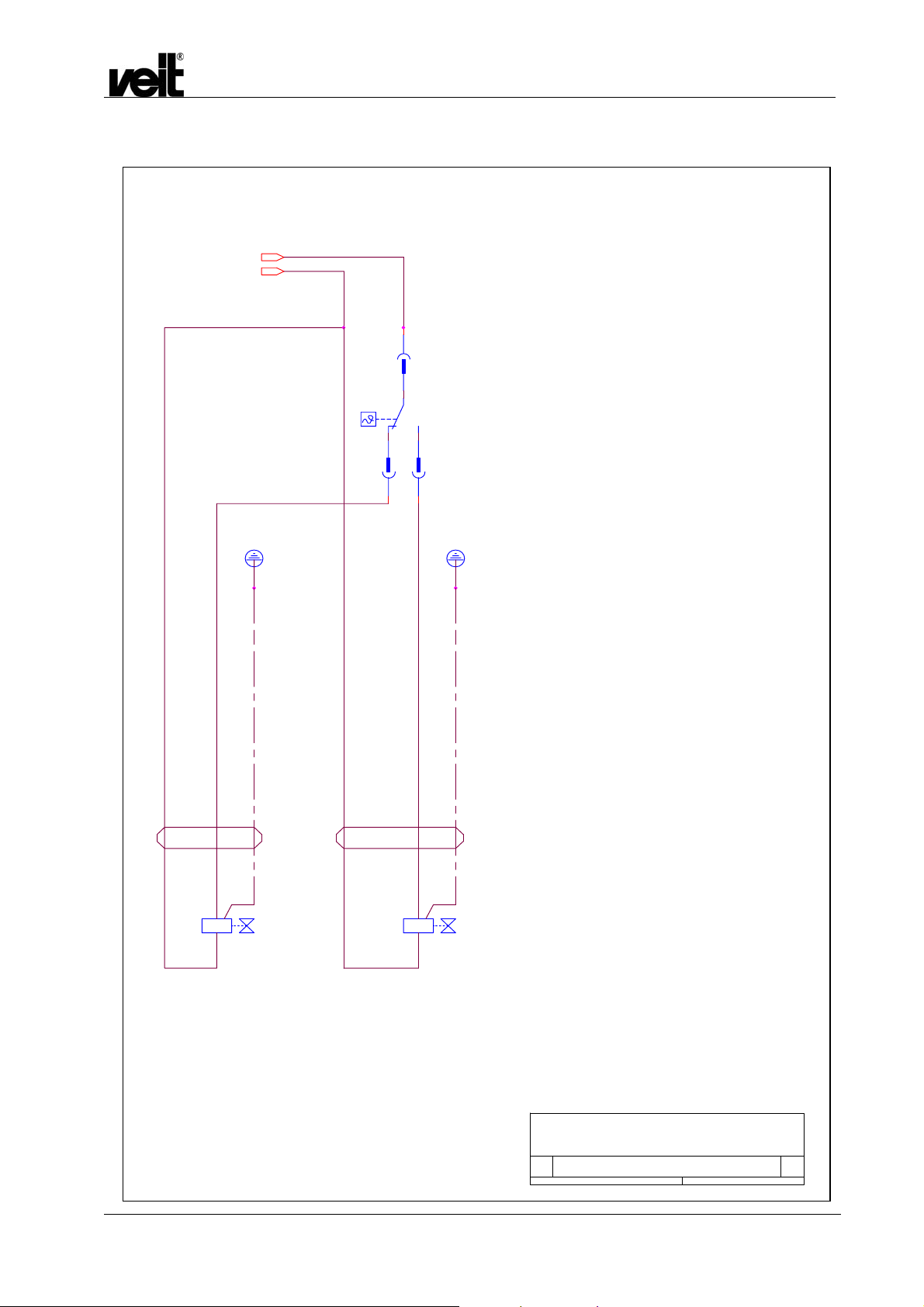
39 kW / 400 V, 50 Hz
W16
A1
Y3
A2
Speisewasser-Temperaturbegrenzung
Temperature limiting of feedwater
U_st_L1
U_st_N
76
X5
1
N2
24
PE
W15
A1
Y2
A2
PE
Dampfstation VEIT 2380 12 kW / 26 kW / 39 kW / 52 kW
VEIT 2380 Steam Station 12 kW / 26 kW / 39 kW / 52 kW
31.01.2007
Speisewasserbehälter
condensate to the
feedwater tank
Kondensat zum AbflussKondensat zum
condensate to
the outlet
DE 2380
Speisewasser-Temperaturbegrenzung
380...400V, 50/60 Hz
Size Document Number Rev
DE2380_N\2380_395.SCH
A2
Date: Sheet
Temperature limiting of feedwater
380...400 V, 50/60 Hz
of
55Friday, April 30, 1999
35

6.4 52 kW / 400 V, 50 Hz
Dampfstation VEIT 2380 12 kW / 26 kW / 39 kW / 52 kW
VEIT 2380 Steam Station 12 kW / 26 kW / 39 kW / 52 kW
31.01.2007
36
52 kW / 400 V, 50 Hz
Dampfstation VEIT 2380 12 kW / 26 kW / 39 kW / 52 kW
VEIT 2380 Steam Station 12 kW / 26 kW / 39 kW / 52 kW
31.01.2007
37

52 kW / 400 V, 50 Hz
Batteriewechsel und Einstellungen
am Temperaturmessmodul.
- Dampferzeuger ausschalten
- Haltewinkel entfernen
- Batterie entfernen
- Neue Batterie einlegen
- Haltewinkel anbringen
- Taster S2 1 x betaetigen
- Taster S1 druecken, bis 75C
in Display erscheint
- Taster S2 erneut betaetigen
- Taster S3 1 x betaetigen
- Taster S1 druecken, bis 5C
im Display erscheint
- Taster S3 erneut betaetigen
Dampfstation VEIT 2380 12 kW / 26 kW / 39 kW / 52 kW
VEIT 2380 Steam Station 12 kW / 26 kW / 39 kW / 52 kW
Frontplatte
front panel
max. norm. zu niedrig
H9
Maximaldruck
Ueberschreitung
Q1
R1
A2
Zuruecksetzen
reset
battery exchange and adjustment
of the temperature measuring instrument
- turn off the steam generator
- remove the fastening part of the
- remove the battery
- insert a new battery
- mount the fastening part
- push the key S2 one time
- push the key S1, until on the
- push the key S2 one time again
- push the key S3 one time
- push the key S1, until on the
- push the key S3 one time again
X1
3
2
1
max
min
Behaelter leer tank empty
temperature measuring instrument
display occures 75C
display occures 5C
S1 S2 S3
7
6
5
4
+
-
H7
pressure
H5
overflow
X2
1
2
17
16
15
14
13
12
11
10
9
8
H4
343
4
CN3.1
Speisewasser
Temperatur
water supply
temperature
H6
W13
wsge
13
too low
H8
+
-
rtbl
bngn
grrosswwsgnwsrosgrvioblgn
10
23
11
24
12
25
gebngert
17
18
19
20
21
22
9
5
6
7
8
bn
14
15
16
1
2
3
4
31.01.2007
DE 2380
Control Circuit 380...400 V, 50/60 Hz
Title
Steuerstromkreise 380...400V, 50/60Hz
Size Document Number Rev
DE2380_N\2380_393.SCH
A2
Date: Sheet
of
35Friday, April 30, 1999
38

52 kW / 400 V, 50 Hz
Dampfstation VEIT 2380 12 kW / 26 kW / 39 kW / 52 kW
VEIT 2380 Steam Station 12 kW / 26 kW / 39 kW / 52 kW
31.01.2007
39
52 kW / 400 V, 50 Hz
W16
A1
Y3
A2
Speisewasser-Temperaturbegrenzung
Temperature limiting of feedwater
U_st_L1
U_st_N
76
X5
1
N2
24
PE
W15
A1
Y2
A2
PE
Dampfstation VEIT 2380 12 kW / 26 kW / 39 kW / 52 kW
VEIT 2380 Steam Station 12 kW / 26 kW / 39 kW / 52 kW
31.01.2007
Kondensat zum
Speisewasserbehälter
consensate to the
feedwater tank
Kondensat zum
Abfluss
consensate
to the
outlet
DE 2380
Speisewasser-Temperaturbegrenzung
380...400V, 50/60 Hz
Temperature limiting of feedwater
Size Document Number Rev
DE2380_N\2380_525.SCH
A2
Date: Sheet
55Friday, April 30, 1999
of
40

6.5 36 kW / 3x200-220 V, 50/60 Hz
Dampfstation VEIT 2380 12 kW / 26 kW / 39 kW / 52 kW
VEIT 2380 Steam Station 12 kW / 26 kW / 39 kW / 52 kW
31.01.2007
41
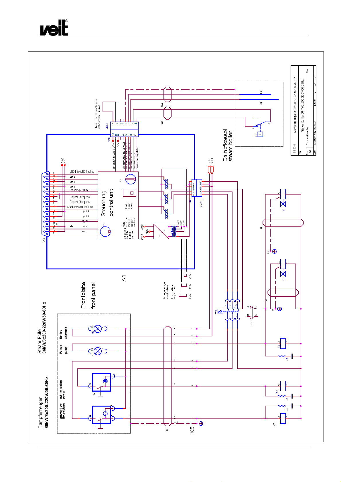
36 kW / 3x200-220 V, 50/60 Hz
Dampfstation VEIT 2380 12 kW / 26 kW / 39 kW / 52 kW
VEIT 2380 Steam Station 12 kW / 26 kW / 39 kW / 52 kW
31.01.2007
42

36 kW / 3x200-220 V, 50/60 Hz
max. norm. zu niedrig
H9
Batteriewechsel und Einstellungen
am Temperaturmessmodul.
- Dampferzeuger ausschalten
- Haltewinkel entfernen
- Batterie entfernen
- Neue Batterie einlegen
- Haltewinkel anbringen
- Taster S2 1 x betaetigen
- Taster S1 druecken, bis 75C
in Display erscheint
- Taster S2 erneut betaetigen
- Taster S3 1 x betaetigen
- Taster S1 druecken, bis 5C
im Display erscheint
- Taster S3 erneut betaetigen
Frontplatte
front panel
Maximaldruck
Ueberschreitung
Q1
S1 S2 S3
R1
A2
X1
1
max
min
Behaelter leer tank empty
Zuruecksetzen
reset
battery exchange and adjustment
of the temperature measuring instrument
- turn off the steam generator
- remove the fastening part of the
temperature measuring instrument
- remove the battery
- insert a new battery
- mount the fastening part
- push the key S2 one time
- push the key S1, until on the
display occures 75C
- push the key S2 one time again
- push the key S3 one time
- push the key S1, until on the
display occures 5C
- push the key S3 one time again
9
8
7
6
5
4
3
2
+
-
Dampfstation VEIT 2380 12 kW / 26 kW / 39 kW / 52 kW
VEIT 2380 Steam Station 12 kW / 26 kW / 39 kW / 52 kW
too low
H7
pressure
H5
overflow
X2
1
2
17
16
15
14
13
12
11
10
H4
343
4
Speisewasser
Temperatur
water supply
temperature
W13
CN3.1
H8
+
H6
-
wsge
rtbl
bngn
23
11
24
12
25
13
grrosswwsgnwsrosgrvioblgn
21
22
10
9
gebngert
bn
14
15
16
17
18
19
20
5
6
7
8
1
2
3
4
31.01.2007
DE 2380
Control Circuit 3 x 220 V, 50/60 Hz
Title
Steuerstromkreise 3 x 200...220V 50/60Hz
Size Document Number Rev
DE2380_N\2380_363.SCH
A2
Date: Sheet
of
35Friday, April 30, 1999
43

36 kW / 3x200-220 V, 50/60 Hz
Dampfstation VEIT 2380 12 kW / 26 kW / 39 kW / 52 kW
VEIT 2380 Steam Station 12 kW / 26 kW / 39 kW / 52 kW
31.01.2007
44

36 kW / 3x200-220 V, 50/60 Hz
Speisewasser-Temperaturbegrenzung
Temperature limiting of feedwater
U_st_L1
U_st_L2
PE
W16
A1
Y3
A2
76
X5
N2
24
W15
Y2
Dampfstation VEIT 2380 12 kW / 26 kW / 39 kW / 52 kW
VEIT 2380 Steam Station 12 kW / 26 kW / 39 kW / 52 kW
1
PE
A1
A2
Kondensat zum
Speisewasserbehälter
condensate to the
feedwater tank
31.01.2007
Kondensat
zum Abfluss
condensate to
the outlet
DE 2380
Speisewasser-Temperaturbegrenzung
3 x 200...220V, 50/60 Hz
Size Document Number Rev
DE2380_N\2380_365.SCH
A2
Date: Sheet
Temperature limiting of feedwater
of
55Friday, April 30, 1999
45
6.6 48 kW / 3x200-220 V, 50/60 Hz
Dampfstation VEIT 2380 12 kW / 26 kW / 39 kW / 52 kW
VEIT 2380 Steam Station 12 kW / 26 kW / 39 kW / 52 kW
31.01.2007
46
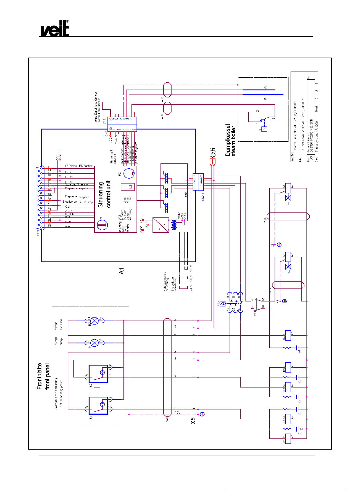
48 kW / 3x200-220 V, 50/60 Hz
Dampfstation VEIT 2380 12 kW / 26 kW / 39 kW / 52 kW
VEIT 2380 Steam Station 12 kW / 26 kW / 39 kW / 52 kW
31.01.2007
47

48 kW / 3x200-220 V, 50/60 Hz
max. norm. zu niedrig
Batteriewechsel und Einstellungen
am Temperaturmessmodul.
- Dampferzeuger ausschalten
- Haltewinkel entfernen
- Batterie entfernen
- Neue Batterie einlegen
- Haltewinkel anbringen
- Taster S2 1 x betaetigen
- Taster S1 druecken, bis 75C
in Display erscheint
- Taster S2 erneut betaetigen
- Taster S3 1 x betaetigen
- Taster S1 druecken, bis 5C
im Display erscheint
- Taster S3 erneut betaetigen
Dampfstation VEIT 2380 12 kW / 26 kW / 39 kW / 52 kW
VEIT 2380 Steam Station 12 kW / 26 kW / 39 kW / 52 kW
Frontplatte
front panel
too low
H9
Maximaldruck
Ueberschreitung
Q1
A2
X1
2
1
max
min
Behaelter leer tank empty
Zuruecksetzen
reset
battery exchange and adjustment
of the temperature measuring instrument
- turn off the steam generator
- remove the fastening part of the
temperature measuring instrument
- remove the battery
- insert a new battery
- mount the fastening part
- push the key S2 one time
- push the key S1, until on the
display occures 75C
- push the key S2 one time again
- push the key S3 one time
- push the key S1, until on the
display occures 5C
- push the key S3 one time again
R1
5
4
3
H7
H5
S1 S2 S3
10
9
8
7
6
H4
+
-
pressure
overflow
X2
1
2
17
16
15
14
13
12
11
343
4
Speisewasser
Temperatur
water supply
temperature
W13
CN3.1
H6
wsge
25
13
H8
+
-
rtbl
bngn
grrosswwsgnwsrosgrvioblgn
21
22
10
23
11
24
12
9
gebngert
bn
14
15
16
17
18
19
20
5
6
7
8
1
2
3
4
31.01.2007
DE 2380
Control Circuit 3 x 220 V, 50/60 Hz
Title
Steuerstromkreise 3 x 200...220V 50/60Hz
Size Document Number Rev
A2
DE2380_N\2380_363.SCH
Date: Sheet
of
35Friday, April 30, 1999
48

48 kW / 3x200-220 V, 50/60 Hz
Dampfstation VEIT 2380 12 kW / 26 kW / 39 kW / 52 kW
VEIT 2380 Steam Station 12 kW / 26 kW / 39 kW / 52 kW
31.01.2007
49

48 kW / 3x200-220 V, 50/60 Hz
Speisewasser-Temperaturbegrenzung
Temperature limiting of feedwater
U_st_L1
U_st_L2
76
X5
Dampfstation VEIT 2380 12 kW / 26 kW / 39 kW / 52 kW
VEIT 2380 Steam Station 12 kW / 26 kW / 39 kW / 52 kW
N2
24
1
PE
PE
W16
W15
31.01.2007
A1
Y3
A2
Kondensat zum
Speisewasserbehälter
condensate to the
feedwater tank
A1
Y2
A2
Kondensat
zum Abfluss
condensate to
the outlek
DE2380
Speisewasser-Temperaturbegrenzung
3 x 200...220V, 50/60Hz
Size Document Number Rev
A2
Date: Sheet
DE2380_N\2380_485.SCH
Temperature limiting of feedwater
of
55Friday, April 30, 1999
50
Dampfstation VEIT 2380 12 kW / 26 kW / 39 kW / 52 kW
VEIT 2380 Steam Station 12 kW / 26 kW / 39 kW / 52 kW
7 EG-Konformitätserklärung / EC Declaration of conformity
31.01.2007
51

Dampfstation VEIT 2380 12 kW / 26 kW / 39 kW / 52 kW
VEIT 2380 Steam Station 12 kW / 26 kW / 39 kW / 52 kW
31.01.2007
52

Dampfstation VEIT 2380 12 kW / 26 kW / 39 kW / 52 kW
An:
Fa. VEIT - Service Justus-von-Liebig Str. 15
D- 86899 Landsberg / Lech
Germany
Fax: +49 (8191) 479 - 230
E-mail: service@veit.de
VEIT ist ständig bemüht, die Produkte zu verbessern. Dazu sind wir auf Ihre Mithilfe angewiesen. Durch die Registrierung
können Ihnen technische Verbesserungen direkt mitgeteilt werden.
1.) Wie wurden Sie auf das Produkt aufmerksam?
VEIT Mitarbeiter / Händler Internet
VEIT 2380 Steam Station 12 kW / 26 kW / 39 kW / 52 kW
Registrierung
Messe __________________ Sonstiges ____________
Zeitschrift ________________
2.) Wie beurteilen Sie folgende Themen:
gut mangelhaft
Unterstützung bei der Verkaufsentscheidung
Installation
Einweisung
Handbuch
Bedienung des Gerätes
Arbeitsergebnis
Qualität der Maschine
3.) Verbesserungsvorschläge:
_________________________________________________________
_________________________________________________________
_________________________________________________________
Adresse:
Name: ___________________________________
Straße: ___________________________________
Ort/Land: ___________________________________
Tel: ___________________________________
Fax: ___________________________________
Vielen Dank für Ihre Mithilfe!
31.01.2007
53

Dampfstation VEIT 2380 12 kW / 26 kW / 39 kW / 52 kW
To:
VEIT - Service Justus-von-Liebig Str. 15
D- 86899 Landsberg / Lech
Germany
Fax: +49 (8191) 479 - 230
E-mail: service@veit.de
VEIT always tries to improve its products. To do this, we need to be supported by you. We will register your answers,
which will enable us to inform you directly about any technical improvements.
1.) How did you become aware of the product?
VEIT 2380 Steam Station 12 kW / 26 kW / 39 kW / 52 kW
Registration
2.) What is your opinion about the following points:
good bad
Support at the sales decision
Installation
Instruction
Manual
Operation of the unit
Result of the operation
Quality of the machine
3.) Suggestions for improvement:
_________________________________________________________
_________________________________________________________
_________________________________________________________
VEIT employee / dealer
Exhibition __________________
Magazine ________________
Internet
Other ____________
Address:
Name: ___________________________________
Street: ___________________________________
Place/Country: ___________________________________
Phone: ___________________________________
Fax: ___________________________________
Thank you for your help!
31.01.2007
54
 Loading...