

Betriebsanleitung
Operating Instructions
Pressing for Excellence
TD2305_i20081001.doc
Dampferzeuger Hodamat
VEIT 2305
Hodamat Steam Generator

Dampferzeuger Hodamat VEIT 2305
VEIT 2305 Hodamat Steam Generator
VEIT GmbH
Justus-von-Liebig-Str. 15
D - 86899 Landsberg am Lech
Germany
Phone +49 (81 91) 479 0
Fax +49 (81 91) 479 149
www.veit-group.com
Service Hotline
Germany: +49 (81 91) 479 133
Europe: +49 (81 91) 479 252
America: +1 (770) 868 8060
Asia: +852 2111 9795
Ersatzteile/Spare Parts
Vertrieb/Sales +49 (8191) 479 176
Vertrieb Textilpflege/ +49 (8191) 479 129
Sales Textile care
01.10.2008 2

Dampferzeuger Hodamat VEIT 2305
VEIT 2305 Hodamat Steam Generator
Inhaltsverzeichnis / Table of Contents:
1 Warnhinweise / Warnings 4
2 Sicherheitshinweise für die Arbeit mit dem
Dampferzeuger VEIT 2305 / Safety Instructions for
working with the Steam Generator VEIT 2305 4
3 Betriebsanleitung / Operating Instructions 5
3.1 Technische Daten / Technical Data 6
Artikelnummer 7
Elektrischer Anschluss 7
Maße und Gewichte 7
3.1.1 Kesselinhalt / Boiler Capacity 8
3.1.2 Heizleistung und Anschlusswert / Heating Power and Connected Load 8
3.1.3 Anheizzeit / Heating-Up Time 8
3.1.4 Dampf und Druck / Steam and Pressure 8
3.2 Aufstellung / Installation 8
3.3 Vor Inbetriebnahme der Dampferzeuger / Prior to Commissioning the Steam Generator 9
3.4 Befüllung / Filling 9
3.5 Nachfüllen während des Betriebes / In-Operation Refilling 10
3.6 Außerbetriebnahme / Shut-Down 10
3.7 Kesselreinigung (Abschlämmung) / Boiler Cleaning and Blow-down 10
3.7.1 Sicherheitshinweise / Safety Instructions 10
3.7.2 Abschlämmen / Blow-down 11
3.8 Weitere Funktionen und Sicherheitseinrichtungen / Further Functions and Safety Features 12
3.9 Wartung und Plege / Maintenance and Service 13
4 Ersatzteile Dampferzeuger Hodamat / Spare Parts
Steam Generator Hodamat 14
4.1 Zeichnungen / Drawings 14
4.2 Ersatzteilliste / Spare Parts List 18
5 Ersatzteile SEM-Pumpe / Spare Parts SEM-Pump 20
6 Merkblatt 2305-007 / Information Leaflet 2305-007 21
7 Stückliste zu Schaltplan 2305 / Parts List for Circuit
Diagram 22
8 Schaltpläne / Circuit Diagrams 24
9 Aufbau der Ergänzung von Klemmleiste X5 /
Assembling of complement strip terminal X5 28
10 Service- und Pflegeanleitung / Service and
Maintenance Instructions 29
11 EG-Konformitätserklärung / EC Declaration of
Conformity 32
01.10.2008 3

1 Warnhinweise / Warnings
STÖRUNGEN AN DER ELEKTRISCHEN ANLAGE
DÜRFEN NUR DURCH ELEKTROFACHKRÄFTE
BEHOBEN WERDEN.
VOR ÖFFNEN DES GERÄTES HAUPTSCHALTER IN
STELLUNG „0“ BRINGEN UND NETZSTECKER ZIEHEN.
IM GEFAHRENFALL NETZSTECKER ZIEHEN!
DIE ABSCHLÄMMUNG DARF NUR DURCH
EINGEWIESENES PERSONAL UND NUR UNTER
EINHALTUNG DER VORGESCHRIEBENEN
SICHERHEITSHINWEISE ERFOLGEN.
NACH DEM ABSCHLÄMMEN MUSS DER
ABSCHLÄMMHAHN MIT DEM SICHERHEITSBÜGEL
VERRIEGELT WERDEN.
BEI VERWENDUNG VON SCHWIMMERBEHÄLTERN;
DIESE NICHT UNBEAUFSICHTIGT BETREIBEN.
IN BETRIEBSPAUSEN ABSPERRHAHN SCHLIESSEN.
DAS GERÄT VOR FROST SCHÜTZEN.
Dampferzeuger Hodamat VEIT 2305
VEIT 2305 Hodamat Steam Generator
ELECTRICAL FAULTS MUST ONLY BE REPAIRED BY
AUTHORIZED PERSONNEL.
BEFORE OPENING THE MACHINE SET THE MAIN SWITCH
TO POSITION "0" AND DISCONNECT.
IN CASE OF EMERGENCY PULL THE MAINS PLUG.
BLOW-DOWN MUST ONLY BE PERFORMED BY TRAINED
PERSONNEL AND ONLY BY FOLLOWING THE STIPULATED
SAFETY INSTRUCTIONS.
THE BLOW-DOWN BALL VALVE HAS TO BE LOCKED WITH
THE SAFETY BOW AFTER-BLOW-DOWN.
WHEN USING FLOAT TANKS, DON’T OPERATE THIS
UNATTENDED
DURING OPERATION BRAKE CLOSE THE STOP COCK
PROTECT THE UNIT FROM FROST.
2 Sicherheitshinweise für die Arbeit mit dem Dampferzeuger VEIT 2305 / Safety
Instructions for working with the Steam Generator VEIT 2305
Der Dampferzeuger ist ausschließlich für die Erzeugung von
Dampf zur Verwendung in Bügelgeräten und Detachierpistolen
konzipiert.
Der Dampferzeuger ist für den Betrieb mit normalem oder
enthärtetem Leitungswasser geeignet. Der Zusatz des
Kalkbindemittels Lapidon in der in Abschnitt 3.7.2 genannten
Dosierung ist zulässig. Bei Zusatz anderer Chemikalien
übernimmt VEIT keine Haftung für Funktion und Sicherheit des
Geräts.
Bei der Aufstellung des Dampferzeugers muss sichergestellt
werden, dass
• der Abschlämmhahn auf der Geräterückseite nicht
versehentlich geöffnet werden kann
• Anschlusskabel, Abschlämmschlauch und
Abschlämmbehälter keine Stolperfallen darstellen
• Dampfventile und Sicherheitsventil nicht zufällig berührt
werden können.
Dampfschläuche vor Arbeitsbeginn auf Beschädigungen
überprüfen. Abgenutzte oder versprödete Schläuche umgehend
ersetzen.
Dampfventile nicht berühren. Verbrennungsgefahr!
Dampfstrahl nicht auf Personen richten. Verbrennungs- und
Verbrühungsgefahr!
Dampfstrahl nicht gegen Gerät richten. Gefahr von Schäden in
der Elektrik!
Beim Abschlämmen sorgfältig vorgehen. Verbrühungsgefahr!
Zur Durchführung des sicheren Abschlämmens unbedingt die
Anleitung in Abschnitt 3.7.2 sowie die Sicherheitshinweise in
Abschnitt 3.7.1 dieser Betriebsanleitung befolgen.
Wenn Dampf aus dem Gerät austritt, sofort Gerät stillsetzen und
Leck fachgerecht beheben lassen.
Bitte beachten Sie die Wartungshinweise in Abschnitt 3.9 dieser
Anleitung.
The steam generator is exclusively designed for the production
of steam for the use in ironing units and spotting pistols.
The steam generator is suited for operation with normal or
softened tap water. The addition of the decalcifying agent
Lapidon is allowed, as described under section 3.7.2. If other
chemicals are added, VEIT bears no responsibility for any
resulting damage and for the function and safety of the machine.
During the installation of the steam generator the following points
have to be ensured:
• the blow-down ball valve and the vent valve on the back
side of the unit cannot be inadvertently opened.
• the connection cable, blow-down hose and blow-down tank
cannot be tripped over.
• the steam valve and the safety valve cannot be accidentally
touched.
Check the steam hose for damage before use. Replace worn
and brittle hose immediately.
Do not touch steam valve. Danger of burning and scalding!
Do not point steam jet at people. Danger of burning and
scalding!
Do not point steam jet at machine. Danger of damage to the
electrics!
Proceed with care when blowing-down. Danger of scalding!
Please following closely the instructions in section 3.7.2 as well
as the safety instructions in section 3.7.1 of these operating
instructions to ensure safe blow-down.
If steam escapes from the unit, shut down the machine
immediately and have the leak repaired by a specialist.
Please pay attention to chapter 3.9 maintenance and service of
these operating instructions.
01.10.2008 4

3 Betriebsanleitung / Operating Instructions
08 Betriebsschalter
09 Betriebsstundenzähler
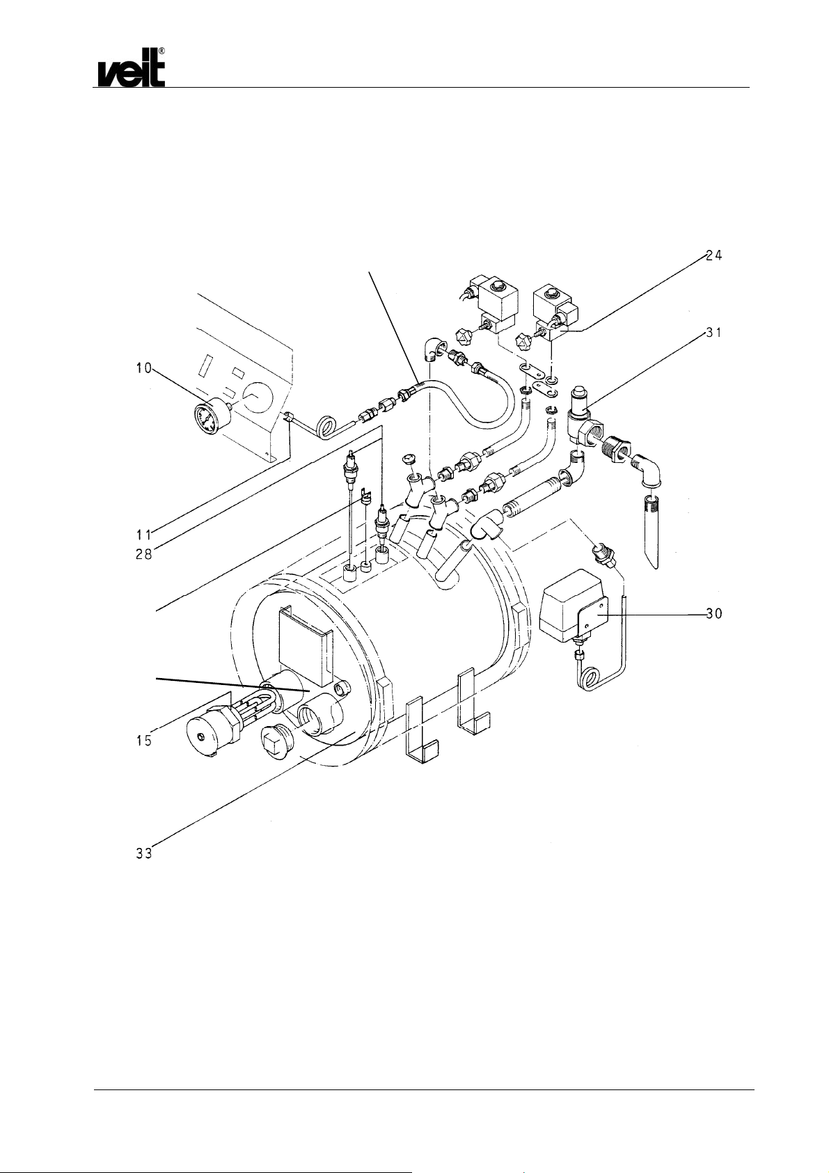
10 Manometer kpl.
12 Minimalkontroll-Lampe rot
13 Minimalkontroll-Lampe weiß
14 Schiebeschalter für Dampfbügler links und rechts
14a Entlüftungsschalter
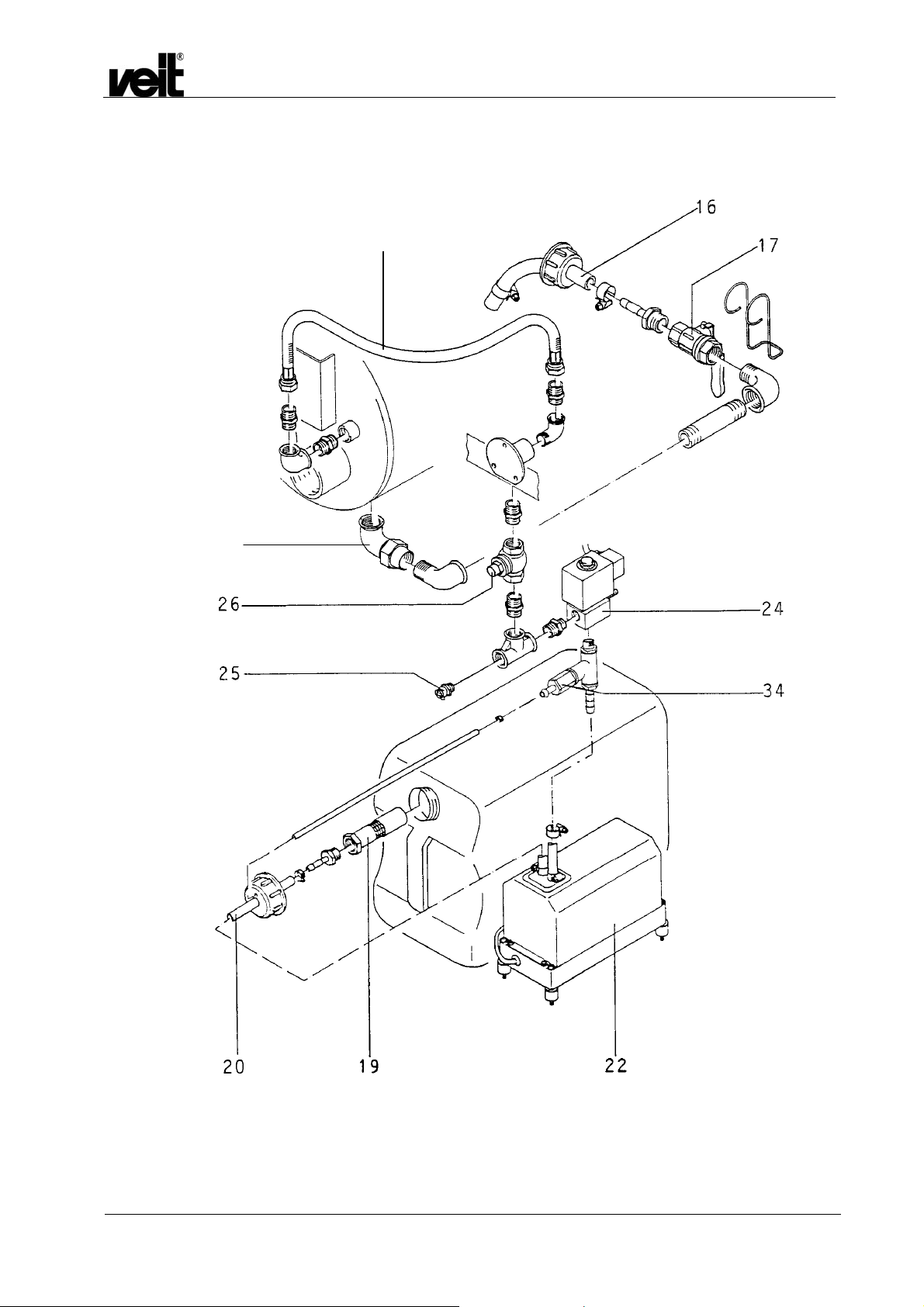
16 Abschlämmschlauch mit Diffusor
17 Abschlämmventil mit Sicherheitsventil
18 Laufrollen
19 Ansaugfilter kpl.
20 Befüllschlauch
22 SEM-Pumpe
24 Dampfventil m. Drosselschraube
25 Entlüftungsventil
27 Plastikgriff
29 Spezialkleinsteckdose
31 Sicherheitsventil
50 Speisewasserbehälter
51 Wasseranschlussnippel (wenn Behälter mit
Schwimmerventil Art. Nr. 423 038 002 0)
52 CEKON-Stecker
53 Überdruckabblasrohr
08 Main switch
09 Working hour meter
10 Pressure gauge, cpl.
12 Min. level indicator, red
13 Max. level indicator, white
14 Slide switch, l/r steam iron
14a Venting switch
16 Blow-down hose (must be attached)
17 Blow-down valve
18 Casters
19 Suction filter, cpl.
20 Filling hose
22 SEM pump
24 Steam valve w. throttle screw
25 Venting valve
27 Plastic handle, cpl.
29 Special socket
31 Safety valve (relief valve)
50 Feedwater tank
51 Water connection nipple(if fitted with
float tank Art. No. 423 038 002 0)
52 Cekon-plug
53 Pressure release tube
Dampferzeuger Hodamat VEIT 2305
VEIT 2305 Hodamat Steam Generator
01.10.2008 5
3.1 Technische Daten / Technical Data
Dampferzeuger Hodamat VEIT 2305
VEIT 2305 Hodamat Steam Generator
01.10.2008 6

Dampferzeuger Hodamat VEIT 2305
VEIT 2305 Hodamat Steam Generator
Modell VEIT 2305
4,5 kW
VEIT 2305
6,0 kW
Artikelnummer 1230510010 1230510020
Elektrischer Anschluss
Volt 400 400
Hz 50-60 50-60
kW 4,5 6,0
A
Netzseitige Absicherung
Wasseranschluss 30 l Tank 30 l Tank
Dampfanschluss Zoll 1/2 1/2
Betriebsdruck bar 4,0 4,0
Einstellbar auf bar max. 5,0 max. 5,0
Dampfmenge kg/h 5,8 7,8
Dampfverbraucher 2 Bügler 2 Bügler
Maße und Gewichte
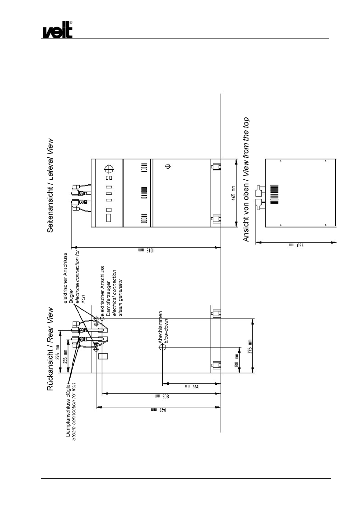
Breite mm 465 465
Höhe mm 1050 1050
Tiefe mm 550 550
Gewicht kg 74 74
Model VEIT 2305
4.5 kW
Article number
Electrical Connection
1230510010 1230510020
VEIT 2305
6.0 kW
Volt 400 400
Hz 50-60 50-60
kW 4.5 6.0
A
Fuse protection
Water connection 30 l Tank 30 l Tank
Steam connection inch 1/2 1/2
Working pressure bar 4.0 4.0
Adjustable to bar max. 5.0 max. 5.0
Steam output kg/h 5.8 7.8
Steam user 2 irons 2 irons
Dimensions and weight
Width mm / inch 465 / 18 465 / 18
Height
Depth
mm / inch
mm / inch
1050 / 41 1050 / 41
550 / 22 550 / 22
Weight kg / lbs 74 / 163 74 / 163
Anschluss-Stellen 2
Speisewasserbehälter 30 Liter
Connection points 2
Feedwater tank 30 l
01.10.2008 7

3.1.1 Kesselinhalt / Boiler Capacity
Wasserinhalt 8,8 Liter NW / 9,3 Liter HW
Kesselvolumen 15 Liter
3.1.2 Heizleistung und Anschlusswert / Heating Power and Connected Load
4500 Watt / 6000 Watt
mit 2 HD-Bügeleisen ca. 7000 Watt / 8500 Watt
Anschluss 220/380 Volt Drehstrom
Mittelleiter und Schutzleiter
nach VDE getrennt
3.1.3 Anheizzeit / Hea ting -Up Ti me
ca. 15 Minuten
Water volume 8.8 l min. water level /9.3 l
Boiler capacity 15 l
4500 W / 6000 W
if fitted with 2 HP irons 7000 W / 8500 W approx.
Power Supply 220/380 V Three-phase current
approx. 15 minutes
Dampferzeuger Hodamat VEIT 2305
VEIT 2305 Hodamat Steam Generator
max. water level
neutral wire and earth
separated according to VDE
regulations
3.1.4 Dampf und Druck / Steam and Pressure
Normarbeitsdruck 3,5 - 4 bar
zul. Betriebsüberdruck 6 bar
Dampftemperatur bei 3,5 - 4
bar
Dampfleistung ca. 5,8 kg/h / 7,8 kg/h
VEIT 2305 mobiler Dampferzeuger auf Laufrollen mit
vollautomatischer, elektronischer Steuerung.
Speisewasserbefüllung aus Speisewasserbehälter (50) mit
selbstansaugender Elektro-Membranpumpe (22) elektronisch
gesteuert.
147 - 151°C
3.2 Aufstellung / Installation
Nachdem das Gerät aus der Verpackung genommen wurde,
werden die inliegenden Laufrollen (18) montiert. Die Handgriffe
(27) ermöglichen leichten Transport und Mobilität.
Normal operating pressure 3.5 - 4 bars
Admissible design pressure 6.0 bars
Steam temperature at 3.5-4
bars
Steam capacity approx. 5.8 kgs/h - 7.8 kgs/h
VEIT 2305 mobile steam generator on casters, equipped with a
full automatic, electronic control system. Filling by feedwater tank
(50) with a self-priming electric membrane pump (22),
electronically controlled.
After unpacking the steam generator the enclosed rollers (18)
have to be fitted. Transport and mobility with effortless ease (27).
147 - 151°C
01.10.2008 8

Dampferzeuger Hodamat VEIT 2305
VEIT 2305 Hodamat Steam Generator
3.3 Vor Inbetriebnahme der Dampferzeuger / Prior to Commissioning the Steam Generator
Achtung!
Wer Änderungen am Gerätestecker (CEKON-Stecker) vornimmt
oder ihn durch einen anderen Stecker ersetzt, haftet für die
richtige Klemmung der einzelnen Kabeladern und etwaige
nachteilige Folgen.
Die einzelnen Adern des Gerätekabels sind nach den
europäischen Bestimmungen in ihrer Funktion wie folgt:
blau = Mittelleiter
grün/gelb = Schutzleiter
schwarz = Phasen L1 + L3
braun = Phase L2
Bitte prüfen Sie, ob Steckdose mit der Funktion der einzelnen
Kabeladern des CEKON-Steckers (52) übereinstimmt. Vor
Inbetriebnahme werden die Hochdruckdampfbügler am Gerät
angeschlossen. Hochdruckdampfschlauch mit Verschraubung
3/8" an Dampfventil (24) rückseitig am Gerät anschließen.
Ebenso Anschlusskabel mit Spezialkleinstecker an
Spezialkleinsteckdose (29) anschließen. Befüllschlauch (20) bis
zum Boden des Speisewasserbehälters (50) einlegen.
Caution!
Care must be taken to wire up and plug correctly to avoid serious
consequences. On modification or replacement of device plug
you are fully responsible for correct clamping.
Wiring according to European Specifications:
blue = neutral
green/yellow = earth
black = phases L1 + L3
brown = phase L2
Please check whether the terminals of the Cekon outlet coincide
with the function of individual leads terminated on Cekon-type
plug (52). Prior to commissioning, connect the high-pressure
steam irons to the system. Use 3/8" fitting to connect up highpressure steam hose to steam throttle (24) at the rear wall of the
unit. Moreover, use special miniature plug to connect cable up to
special miniature socket (29). Insert refilling hose (20) until it
touches the bottom of feedwater tank (50).
3.4 Befüllung / Filling
Der Dampferzeuger DE 2305 ist ab Werk mit einem
Vorratsbehälter ausgestattet, der manuell befüllt wird.
Optional kann auch ein Wasserbehälter mit Schwimmer (Art.nr.
4230380020) verwendet werden.
Für direkten Anschluss an die Wasserleitung ist dieser
Dampferzeuger nicht vorgesehen.
Wenn das Gerät mit einem Speisewasserbehälter mit
Schwimmer ausgerüstet ist (gesondert bestellt), wird es über den
Hochdruckschlauch und rückseitigen Nippel (51) an die
Wasserleitung angeschlossen. Über den im Gerät eingebauten
Speisewasserbehälter mit oder ohne Schwimmer wird somit die
Wasserversorgung gewährleistet.
Bitte beachten Sie das Merkblatt IL2365-004, das dem
Schwimmerbehälter beiliegt!
Betriebsschalter (08) und Entlüftungsschalter (14a) einschalten.
Minimalkontroll-Lampe rot (12) leuchtet auf. Die Membranpumpe
(22) befüllt jetzt automatisch den Kessel bis zur Maximalstufe.
Die Kontroll-Lampe rot erlischt und die Maximalkontroll-Lampe
weiß (13) leuchtet auf. Gleichzeitig schaltet sich die
Kesselheizung ein. Entlüftungsschalter (14a) nach ca. 5 Minuten
schließen. Nach weiteren 8 Minuten zeigt sich am Manometer
(10) ein Druck von ca. 2 bar. Die beiden Schiebeschalter (14) für
Dampfbügler links und rechts werden eingeschaltet. Nach
Erreichen des Betriebsdruckes von 3,5 bar ist das Gerät
betriebsbereit.
Die erforderliche Dampfmenge kann mit der Drosselschraube
am Dampfventil (24) stufenlos eingestellt werden.
The steam generator DE 2305 is equipped ex factory with a
holding tank, which is filled manually.
Optionally also a water tank with float (art. No. 4230380020) can
be used.
This steam generator is not intended for direct connection to the
water pipe.
If the unit is fitted with a feedwater tank featuring a float (as per
separate order), connect the unit via the high-pressure hose and
the rear-wall nipple (51) to the water mains.
Please attend the information leaflet IL_2365-004, which is
attached to the float tank!
Switch on main switch (08) and air-vent switch (14a).
Red minimum level indicator (12) will light up. Now, the
membrane pump (22) will automatically fill the tank until the
maximum water level has been reached. This will cause the red
indicator to go off, and white maximum level indicator (13) to
come on. Simultaneously, the boiler heating system will be
switched on.
After approx. 5 minutes, close venting switch (14a).
After another 8 minutes, pressure gauge (10) will indicate a
pressure of approx. 2 bars. Switch on the two (14) slide switches
for left and right-hand steam irons. Once the operating pressure
of 3.5 bars has been reached, the unit will be ready for
operation.
Steam quantity is infinitely adjustable at throttle screw at the
steam valve (24).
01.10.2008 9

3.5 Nachfüllen während des Betriebes / In-Operation Refilling
Während des Betriebes füllt sich der Kessel des
Dampferzeugers automatisch. Sinkt der Wasserspiegel durch
Dampfverbrauch auf die Minimalstufe ab, so wird die
elektronische Niveauregelung die Befüllung in Funktion setzen,
(Membranpumpe (22) und elektromagnetisches Befüllventil).
Optische Funktion der Kontroll-Lampen wie vorher beschrieben.
Achtung!
Der Entlüftungsschalter (14a) darf während des Betriebes nicht
betätigt werden.
Sollte die Membranpumpe ungewöhnlich lange laut laufen, so ist
der Speisewasserbehälter leer oder der Schmutzfänger
verschmutzt.
Sollten im Ansaugschlauch Luftblasen sichtbar sein, so ist hierzu
das Entlüftungsventil (25) mit dem anhängenden Schlüssel
während des Pumpens zu öffnen und nach Wasseraustritt
wieder zu schließen. Sollte die Membranpumpe kein Wasser
fördern, so liegt Haftungseffekt beim Ansaugventil vor. Zum
Beheben bitte kurz mit Druckluft in den Ansaugstutzen der
Pumpe blasen. (Den Haftungseffekt kann man auch durch einen
kurzen Anschluss des Ansaugventils an die Wasserleitung
beheben.)
During operation, the boiler will be refilled automatically.
Whenever steam consumption makes the water level drop to its
minimum position, the electronic level control system will trigger
the refilling function (membrane pump (22) and electromagnetic
refilling valve).
Visual controls via indicators, as described above.
Caution!
Never actuate venting switch (14a) during operation.
Whenever pump is running noisily for an unusually long period of
time, the feedwater tank will be empty or the dirt trap will be
clogged.
Should there be any bubbles within the suction hose, open
venting valve (25), using the key attached to it, while the pump is
running; once water appears, close the valve.
If the membrane pump does not deliver any water, there will be
magnetic adhesion. Briefly blow compressed air into suction
sleeve of pump or connect suction valve to water conduit for a
short moment.
Dampferzeuger Hodamat VEIT 2305
VEIT 2305 Hodamat Steam Generator
3.6 Außerbetriebnahme / Shut-Down
Alle Schalter (08, 14) ausschalten.
Achtung!
Nach Arbeitsende ist unbedingt der Wasserzulauf zu schließen.
Switch off all switches (8,14).
Caution!
When stopping work, it will be essential to shut off the water
supply.
3.7 Kesselreinigung (Abschlämmung) / Boiler Cleaning and Blow-down
3.7.1 Sicherheitshinweise / Safety Instructions
Achtung: Unsachgemäßes Abschlämmen bedeutet
Verbrühungsgefahr!
Folgende Sicherheitsmaßnahmen müssen vor jedem
Abschlämmen kontrolliert werden:
• der Abschlämmbehälter muss bis zur Markierung mit
kaltem Wasser gefüllt sein
• der Deckel des Abschlämmbehälters muss zwischen den
beiden Edelstahlschellen fixiert sein
• die Löcher des Diffusors müssen frei von
Kalkablagerungen sein
• der Deckel muss fest auf dem Behälter aufgeschraubt sein
• die Entlüftungsbohrungen des Abschlämmbehälters
müssen frei sein
• der Abschlämmkugelhahn muss langsam geöffnet werden
Inexpert blow-down may cause burning!
Note the following safety instructions before the blow-down:
• The blow-down tank must be filled with cold water up to the
mark.
• The lid of the blow-down tank must be fastened between
the two stainless steel clamps.
• The length of the blow-down hose from the lid to the end of
the diffuser must be approx. 380 mm.
• The holes of the diffuser must not be covered by furring.
• The lid must tightly be screwed on the tank.
• The vent holes of the blow-down tank have not to be
covered by deposits.
01.10.2008 10

Nach dem Abschlämmen:
• muss der Kugelhahn sofort wieder geschlossen werden,
da sonst durch Unterdruckbildung im Kessel das
Abschlämmwasser wieder angesaugt wird
• muss unbedingt der Kugelhahn mit dem Sicherheitsbügel
verriegelt werden
3.7.2 Abschlämmen / Blow-down
Alle Schalter (08, 14) ausschalten. Wasserversorgung schließen.
Der zusätzliche Abschlämmbehälter hat links und rechts des
Einfüllstutzens zwei Entlüftungslöcher.
Der Behälter muss bis zur Markierung mit kaltem Wasser gefüllt
sein. Er wird flachgelegt (siehe Skizze). Der Schraubverschluss
wird bis an die Schlauchklemme herangezogen. Das
Schlauchende wird in den Abschlämmbehälter eingeführt und
der Schraubverschluss fest verschraubt. Es muss sichergestellt
sein, dass der Schlauch nicht aus dem Schraubverschluss
herausgezogen werden kann.
Das Abschlämmventil (17) wird ganz geöffnet. Dadurch ist
gewährleistet, dass Kalkablagerungen voll ausströmen. Der
ebenfalls dabei ausströmende Dampf kondensiert im kalten
Wasser.
cold water up to the
Nach kurzer Zeit ist der Dampfkessel leer.
Die Manometernadel zeigt keinen Druck mehr an.
Unbedingt den Abschlämmbehälter mit dem Sicherheitsbügel
verriegeln.
Das Abschlämmwasser wird weggegossen.
Danach Abschlämmbehälter wieder befüllen; aus
Sicherheitsgründen den Abschlämmschlauch in den Behälter
schieben und Schraubverschluss fest verschrauben.
Es empfiehlt sich, bei hartem Wasser die Abschlämmung jeden
Tag vorzunehmen. Nach Schließen des Abschlämmventils (17)
wird das Gerät sofort wieder befüllt.
Der im Wasser enthaltene Kalk kann zu Ablagerungen im Kessel
und auf den Heizungen führen und Ausfälle hervorrufen. Um
dies zu vermeiden, empfehlen wir ab einer Wasserhärte von
5°dH das Kalkbindemittel Lapidon zu verwenden. Das
Kalkbindemittel bewirkt, dass der im Wasser enthaltene Kalk
gebunden wird und als Schlamm beim Abschlämmen aus dem
Kessel entfernt wird.
Bei einer Wasserhärte von 10°dH bis 15°dH wird
für ca. 10 l Wasser eine halbe Dosierkappe des
mitgelieferten Kalkbindemittels Lapidon
beigegeben. Werden 15°dH überschritten muss
mark
Dampferzeuger Hodamat VEIT 2305
VEIT 2305 Hodamat Steam Generator
• The blow-down ball valve must slowly be opened.
After blow-down:
• The blow-down ball valve must be closed immediately.
Otherwise the water will be sucked in again by the vacuum
in the boiler.
• The blow-down ball valve has to be locked tightly with the
safety bow.
Switch all switches (8, 14) off. Shut off water supply.
The additional drainage tank features two venting holes, one
each to either side of the connection.
Fill cold water into this tank up to the marking indicated. Place it
so that it is wider than high (see drawing). Pull the threaded plug
up to the hose clamp. Introduce the hose end into the drainage
tank and screw down the threaded plug. Make sure that the hose
cannot be pulled out of the screwed connection.
Fully open blow-down valve (17). This will guarantee that any
scale deposits are flushed out of the unit. Any steam coming out
simultaneously will condense within the cold water.
Achtung!
Der Abschlämmschlauch muss
Abschlämmbehälter befestigt sein (Schlauchklemme).
Caution!
The blow-down hose must
drainage tank (jubilee clip).
After a short period of time, the boiler will be empty, and the
gauge needle will show zero pressure.
The blow-down ball valve has to be locked tightly with the safety
bow.
Pour away all the discharge.
Afterwards the blow-down tank has to be refilled again and for
safety reasons push the blow-down hose into the tank and screw
down closely the screw plug.
If you have to operate on hard water, daily blow-down is to be
recommended.
As soon as blow-down valve (17) is closed again, the unit will be
refilled.
The water contains chemicals which may fur the boiler and the
heating elements and may cause malfunctions.
If the water hardness exceeds 5°dH (degrees German
hardness), please use the decalcifying agent Lapidon. This
agent binds the fur and scale deposits contained in the water,
which can be removed from the boiler as sludge during blowdown.
If the water hardness is between 10°dH and 15°dH, add half a
cap of the decalcifying agent Lapidon for approx. 10 l of water. If
unbedingt am oder im
be attached to or within the
01.10.2008 11

Dampferzeuger Hodamat VEIT 2305
eine ganze Dosierkappe für ca. 10 l Wasser
beigefügt werden.
Zu große Mengen Lapidon führen zum Schäumen des
Kesselwassers und Rückstände von Lapidon werden im Dampf
mitgeführt.
Achtung!
Bei Verwendung einer Enthärtungsanlage, z.B. VEIT-Wafi,
entfällt die Verwendung von Lapidon. Allerdings muss die
Abschlämmung auch hierbei unbedingt durchgeführt werden.
the water is harder than 15°dH, add a whole cap for approx. 10 l
of water.
Excessive use of Lapidon will cause foaming of the boiler water
and residues of Lapidon are contained in the steam.
Caution!
When using water softening equipment such as VEIT Wafi, there
is no need to employ any Lapidon. However, blow-down will
remain necessary.
VEIT 2305 Hodamat Steam Generator
3.8 Weitere Funktionen und Sicherheitseinrichtungen / Further Functions and Safety Features
Zu Servicezwecken werden der obere und der vordere
Gerätedeckel abgenommen.
1. Das Sicherheitsventil (bauteilgeprüft) (31) dient als erstes
Sicherheitselement dazu, evtl. auftretenden, höheren
Dampfdruck abzublasen.
Hierbei tritt Dampf am Überdruckabblasrohr (53) aus.
Achtung!
Die Technischen Regeln für Dampfkessel (TRD 421) schreiben
vor, dass Sicherheitsventile entlastbar sein müssen. Deshalb:
1 bis 2 x jährlich Funktionsprüfung des Sicherheitsventils. Dazu
Griffkappe nach links drehen bis Rastung spürbar.
Das Gerät soll dabei unter Dampfdruck stehen.
2. Als zweites Sicherheitselement ist oben der Druckregler
(Pressostat) eingebaut. Dieser steuert den am Manometer
angezeigten Dampfdruck.
3. Als drittes Sicherheitselement ist zwischen den
Messelektroden der Temperaturbegrenzer Heatstop
montiert.
Durch diese TÜV-bauteilgeprüfte Einrichtung ist absoluter
Geräteschutz gewährleistet.
Achtung!
Dieses Element muss nach evtl. Defekt ausgetauscht werden,
nachdem die Defektursache beseitigt ist. Ein Ersatzelement
befindet sich im Gerät.
4. Im stirnseitigen Geräteteil befindet sich die elektrische und
elektronische Steuerung.
5. Zum Schutz der Elektronik ist hierin ein Sicherungselement
eingebaut.
Eine Ersatzsicherung befindet sich angeklebt nebenliegend.
6. Im vorderen Geräteteil befindet sich die Befüllgruppe. Hierin
dienen Elektromagnetventil und Rückschlagventil als
weitere Sicherheitselemente.
Weitere Sicherheitselemente sind: Further features providing security are:
Detachable front and top lid for service purpose.
1. The first safety element permitting any increased steam
pressure to blow off is safety valve (31) (featuring design
approval).
If this valve is actuated, steam will be bled off via pressure
outlet tube (53).
Caution!
The TRD 421 rules and regulations covering boilers provide for
safety-valve pressure relief. Therefore:
check the safety valve 1 - 2 x annually for proper functioning. To
do so, turn the handle cap leftwards until it latches.
During the process, the unit may (but is not required to) be under
steam pressure.
2. The second safety element is provided by the (Pressostattype) pressure controller installed on top. This device
controls the steam pressure as displayed by the gauge.
3. The third safety element provided is the heatstop-type
temperature limiter installed between the measuring
electrodes.
Thanks to this safety feature approved by TÜV (German
Technical Examination Association) the unit may be
guaranteed to be safe.
Caution!
It may be necessary to remove this system whenever any defect
has been repaired. A replacement system is located within the
unit.
4. The front section of the unit houses all electric and
electronic controls.
5. To protect the electronic systems, there is a built-in safety
fuse.
Next to it, a replacement fuse is taped down on to the
system.
6. The front unit section houses, moreover, the refilling
system.
Solenoid and check valves provide additional security.
01.10.2008 12

7. Edelstahlheizpatrone
8. Sicherungsbügel für Abschlämmhahn
9. Röhrenfedermanometer
3.9 Wartung und Plege / Maintenance and Service
Täglich:
• Kessel abschlämmen.
• Kontrolle des Abschlämmschlauches und des
Abschlämmbehälters wie unter 3.7.1 beschrieben.
• Die Dichtheit der Kugelhähne überprüfen.
• Die Funktion des Manometers und Druckreglers
überprüfen.
Jährlich oder halbjährlich:
• Die Funktion des Sicherheitsventils muss durch
Anlüften (dazu die Kappe des Sicherheitsventils nach
links drehen) geprüft werden. Der Kessel muss dazu
unter Druck stehen. Durch das Abblasrohr des
Sicherheitsventils muss Dampf nach außen strömen.
• Die Plunger in den Elektromagnetventilen auf Dichtheit
prüfen, ggfs. erneuern.
Jährlich:
• Alle Anschlüsse auf Dichtheit, Korrosion
(Befestigungsschellen) und Festigkeit kontrollieren.
• Alle Funktionsteile (Manometer, Druckregler,
Sicherheitsventil, Rückschlagventil) auf eine
einwandfreie Funktion prüfen.
• Zur Wartung des Kessels Heizungen bzw.
Blindstopfen ausbauen. Das Innere des Kessels, die
Elektrode und die Heizungen von Schmutz und
Kalkablagerungen reinigen.
• Den Befüll- und Abschlämmstutzen auf Kalkreste
kontrollieren und ggf. reinigen.
• Befüll- und Abschlämmleitung demontieren und
reinigen, korrodierte Teile erneuern.
• Sicherheitsventilgruppe und Dampfleitungen
demontieren und reinigen. Korrodierte Teile erneuern.
• Alle Schläuche auf Beschädigungen und
Undichtigkeiten überprüfen.
• Anschlusskabel auf Beschädigungen überprüfen.
Dampferzeuger Hodamat VEIT 2305
VEIT 2305 Hodamat Steam Generator
7. Stainless-steel heating cartridge
8. Safety latch for block-down cock
9. Spring pressure gauge
Daily:
• Drain the boiler.
• Check the blow-down hose and the blow-down tank as
described under chapter 3.7.1.
• Check all ball valves for leakage.
• Inspect the function of the manometer and the pressure
regulator.
Once or twice a year:
• The function of the safety valve must be tested by
venting. To do so, turn the lid of the safety valve to the
left. The boiler must be under pressure. The steam
must escape through the vent-tube of the safety valve.
• Check the plungers in the solenoid valves for leakage,
if necessary replace it.
Yearly:
• Check all the connections for leakage, corrosion
(fastening straps) and tightness.
• Check that all the functioning parts (manometer,
pressure regulator, stop valve, safety valve) work
properly.
• Remove the heating elements and/or blind plug for
maintaining the boiler. Remove any dirt and scale
deposits from the inside of the boiler, the electrodes
and the heating elements.
• Inspect the filling and the drainage plinth for any scale
deposits and clean if necessary.
• Disassemble the filling and drainage line and clean it,
replace corroded parts.
• Disassemble the safety valve group and the steam
lines and clean it. Replace corroded parts.
• Check all hoses for damages and leakiness.
• Check connecting cable for damages.
01.10.2008 13

Dampferzeuger Hodamat VEIT 2305
VEIT 2305 Hodamat Steam Generator
4 Ersatzteile Dampferzeuger Hodamat / Spare Parts Steam Generator Hodamat
4.1 Zeichnungen / Drawings
01.10.2008 14

Dampferzeuger Hodamat VEIT 2305
VEIT 2305 Hodamat Steam Generator
01.10.2008 15
Dampferzeuger Hodamat VEIT 2305
VEIT 2305 Hodamat Steam Generator
41
42
01.10.2008 16
Dampferzeuger Hodamat VEIT 2305
32**
32
•
43
VEIT 2305 Hodamat Steam Generator
01.10.2008 17
4.2 Ersatzteilliste / Spare Parts List
Dampferzeuger Hodamat VEIT 2305
VEIT 2305 Hodamat Steam Generator
Pos. Artikel-Nummer
Article Number
1230510010
1230530010
1230540010
1230510020
1230540020
01
02
03
04
05
07
08
09
10
11
12
13
14
15
16
17
18
19
20
21
22
23
01.10.2008 18
4230550070
4441350220
4252350060
4230550050
4230560200
5851010010
4230550090
4791450010
9290950030
4231530040
4230530180
4430450010
4430450020
4230550030
9280152270
4230560080
4230160020
4310010730
4233040010
4230510170
4230580110
9270530040
4230560000
4230580290
4252350040
Benennung Designation
Dampferzeuger Hodamat 4,5 kW / 400 V
Ab Fabr.-Nr. .......07
Dampferzeuger Hodamat 4,5 kW / 3x220 V
Ab Fabr.-Nr. .......05
Dampferzeuger Hodamat 4,5 kW / 440 V
Ab Fabr.-Nr. .......05
Dampferzeuger Hodamat 6,0 kW / 400 V
Ab Fabr.-Nr. .......07
Dampferzeuger Hodamat 6,0 kW / 440 V
Ab Fabr.-Nr. .......05
Luftschaltschütz 220 V / 50 Hz
Luftschaltschütz 240 V / 50 Hz
Sicherungsautomatik 20 A
Sicherung 0,63 A mittelträge / 250 V (10 Stück)
Trafo 220 V / 24 V 3 VA kurzschlusssicher
Sicherung 1 A / mittelträge / 10 Stück
Elektronik einzeln (steckbar)
Geräteschalter Wippe grün
Betriebsstundenzähler 220 V / 240 V / 50 Hz
Manometer 0 - 10 bar
Kupferschlange / Manometer
Kontroll-Lampe rot
Kontroll-Lampe weiß
Schiebeschalter mit Kontroll-Lampe (bis 09/08)
Schiebeschalter mit Kontroll-Lampe (ab 10/08)
Heizung 4,5 kW / 400 V mit Dichtung
Heizung 3,0 kW / 400 V mit Dichtung
Auslaufschlauch 1.000 mm ½“
Kugelhahn ½“
Rollensatz kpl. (4 Stück)
Ansaugfilter kpl.
Schlauch PVC mit Einlage Dm 6x3 (LM)
Anschlusskabel 4,2 m
SEM-Pumpe 220 V / 240 V / 50 Hz / 60 Hz
Relaissockel 11-polig
Hodamat steam generator 4.5 kW / 400 V
serial no. .....07 and above
Hodamat steam generator 4.5 kW / 3x220 V
serial no. …..05 and above
Hodamat steam generator 4.5 kW / 440 V
serial no. .....05 and above
Hodamat steam generator 6.0 kW / 400 V
serial no. .....07 and above
Hodamat steam generator 6.0 kW / 440 V
serial no. .....05 and above
Air type contactor, 220 V / 50 Hz
Air type contactor, 240 V / 50 Hz
Safety cut-out 20 A
0.63 A / 250 V fuses, semi time lag (10 fuses)
Transformer 220 V/ 24 V, 3 VA short circuit-proof
Fuse 1 A /semi time-lag/10 pieces
Individual electronics system (pluggable)
Switch green
Working hour meter, 220 V / 240 V / 50 Hz
Pressure gauge 0-10 bar
Copper tube serpentine / pressure gauge
Red indicating lamp
White indicating lamp
Slide switch with indicating lamp (until 09/08)
Slide switch with indicating lamp (from 10/08)
Heating element 4.5 kW / 400 V with sealing
Heating element 3.0 kW / 400 V with sealing
Outlet hose 1000 mm, 1/2"
Ball cock, 1/2"
Set of rolls, cpl. (4 pieces)
Suction filter, cpl.
PVC hose diameter 6x3 with layer (r. m.)
Connection cable 4.2 m
SEM pump 220 V / 240 V, 50 Hz / 60 Hz
Relay header 11-score

Pos. Artikel-Nummer
Article Number
24
25
26
27
28
29
30
31
32
32**
33
34
35
36
37
38
39
40
41
42
43
9290650180
423323018G
4283210000
4233230130
4231270030
4310020190
4230520120
423058013G
4400000370
4230540230
9290650110
9290650440
4230560110
4230535060
2221701000
9290650590
9230350140
9230350160
9230350170
9230350290
9230350300
9230350130
9410910520
2140110170
4231230120
Dampferzeuger Hodamat VEIT 2305
VEIT 2305 Hodamat Steam Generator
Benennung Designation
EMV I NW 2,8 200-254 V / 50-60 Hz
Plunger kpl. (3 Stück)
Spule 200-254 V / 50-60 Hz
Stopfbuchse mit Spindel und Dichtung
Entlüftungshahn ¼“
Rückschlagventil 3/8“
Plastikgriff kpl.
Elektroden kpl.
Spezialeinsteckdose spezial 4-polig
Druckwächter
Sicherheitsventil 6 bar ½“
Sicherheitstemperaturbegrenzer ab Fabrikations-
Nummer ........07
Temperaturbegrenzer Heatstop bis Fabrikations-
Nummer ........06
Dampfkessel
Lapidon 1 Karton à 4 Flaschen
Überdruckventil
Klemme EK 2,5/35 gnge
Klemme EK 6/35 gnge
Klemme SAK 6/35
Klemme DK 4QV/35
Klemme DK 4Q/35
Klemme ASK 1/35 für Sicherung 0,63 A
Winkelverschraubung ½“ I-I Zu
Panzerschlauch 3/8“x350
Panzerschlauch ¼“x350
Solenoid valve I NW 2.8 200-254 V/50-60 Hz
Plunger cpl. (3 pieces)
Coil 200-254 V/50-60 Hz
Bushing with spindle and seal
Air-vent valve, 1/4"
Check valve, 3/8"
Plastic handle cpl.
Electrodes cpl.
Special miniature socket, 4 pins
Pressure control device
Safety valve 6 bars 1/2"
Safety heat-stop from serial
number ........07 and above
Heat-stop up to serial number ……..06
Steam boiler
Lapidon 1 box with 4 bottles
Pressure control valve
Clamp EK 2.5/35 green-yellow
Clamp EK 6/35 green-yellow
Clamp SAK 6/35
Clamp DK 40QV/35
Clamp DK 4Q/35
Clamp ASK 1/35 for fuse 0.63 A
Screwed joint ½” I-I closed
Reinforced hose 3/8“x350
Reinforced hose ¼“x350
01.10.2008 19
Dampferzeuger Hodamat VEIT 2305
VEIT 2305 Hodamat Steam Generator
5 Ersatzteile SEM-Pumpe / Spare Parts SEM-Pump
07
*) Diese Anschlussadern sind gestreift!
*) These connection leads are striped!
Pos. Artikel – Nummer
Bezeichnung Designation
Article Number
4230580360 Ersatzteilpaket SEM - Pumpe einzeln
4230580290 Selbstansaugende Elektro-Membran-Pumpe
2 4230570350 Abdeckhaube / SEM - Pumpe
3 4230570360 Dichtung / Haube SEM - Pumpe
4 4230580320 Pumpeneinheit / SEM - Pumpe
6 9280150430 Kondensator / SEM - Pumpe
7 4230580360 Ersatzteilpaket SEM-Pumpe (1x Membran, 2x
Feder, 2x Kugel)
Spare part package SEM–pump single
Self-suctioning electro–membrane pump
Covering cap / SEM–pump
Seal / cap SEM–pump
Pump unit / SEM–pump
Capacitor / SEM–pump
Spare parts kit SEM-pump (1x membrane, 2x
spring, 2x ball)
01.10.2008 20
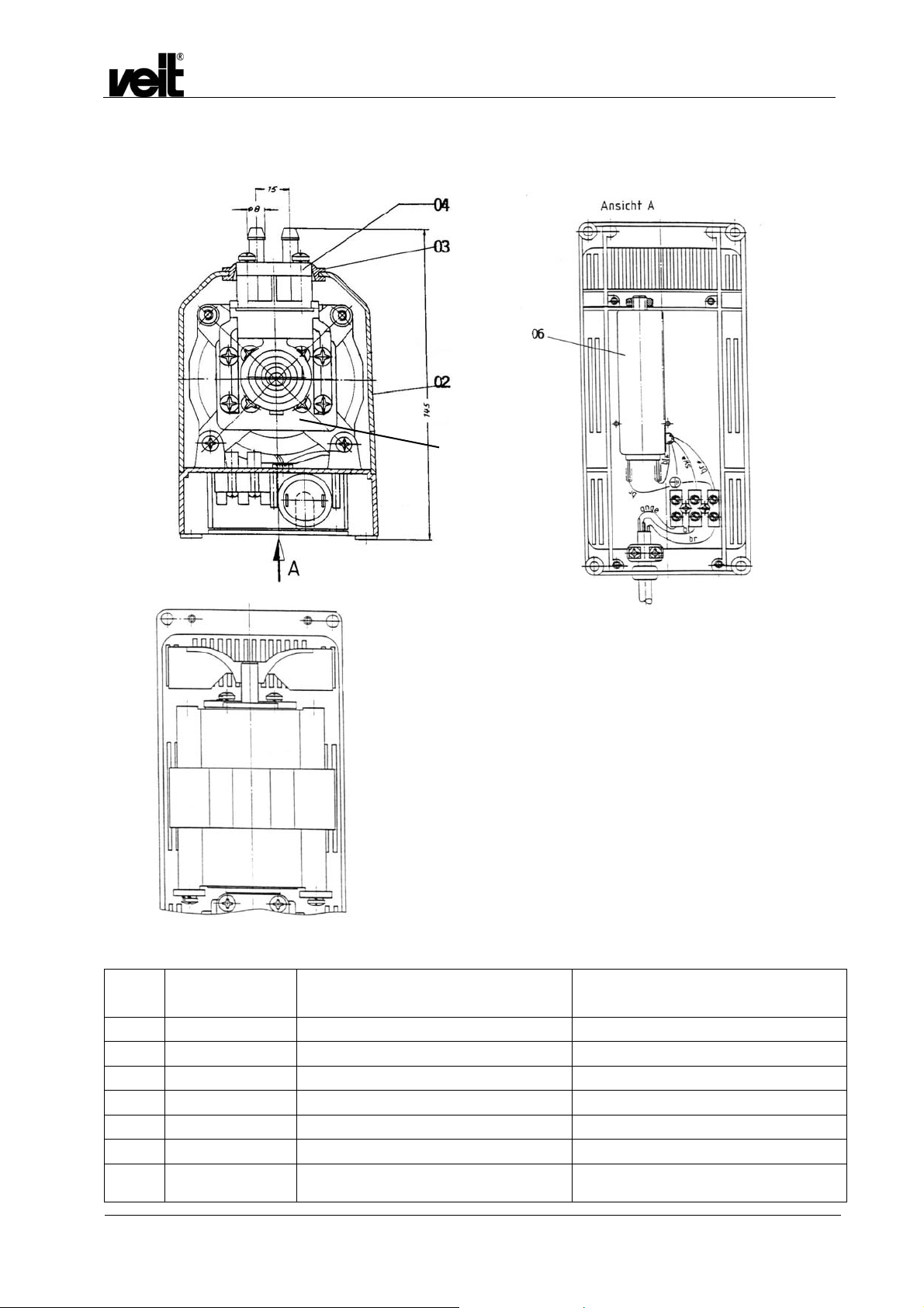
/ View A

6 Merkblatt 2305-007 / Information Leaflet 2305-007
Dampferzeuger Hodamat VEIT 2305
VEIT 2305 Hodamat Steam Generator
Selbstansaugende Elektro-Membran-Pumpe
Art.-Nr. 423 058 029 0
Vor der Montage einer neuen Ersatz-SEM-Pumpe muss man
sich vergewissern, ob
• der Ansaugfilter rein ist
• das Rückschlag- und Magnetventil einwandfrei
funktionieren
• die Zuleitungen bis zum Kessel ohne
Kalkablagerungen sind.
Montageanleitung
• Plastikschlauch und Ansaugfilter mit der Schlauchklemme
an den Ansaugstutzen der Pumpe befestigen.
• Hochdruckschlauch mit der Schlauchklemme an den
Ausgangsstutzen der Pumpe befestigen.
• Elektrische Anschlüsse wie im bereits vorhandenen
Schaltplan aufgeführt.
• Beim Ersetzen einer der Elektroteile Motor (Art.-Nr. 423 058
033 0), oder Kondensator (Art.-Nr. 928 015 043 0)
beachten Sie die Ansicht A der Zeichnung für SEM-Pumpe
(siehe Ersatzteilliste).
Self-priming electrical membrane pump
Art.-No. 423 058 029 0
Before assembling a new spare SEM-pump please make sure
that:
• the suction filter is clean
• the check- and solenoid valves are faultless
• there is no lime scum inside the inlet pipes
Assembly Instructions
• Fasten plastic hose and suction filter to the intake of the
pump. Use jubilee clip for it.
• Fasten high-pressure hose to the outlet sleeve of the pump.
Use jubilee clip for it.
• For electric connections please see the respective circuit
diagram.
• In case of replacement of one of the electrical parts motor
(Art.-No. 423 058 033 0) or capacitor (Art.-No. 928 015 043
0) pay attention to picture A of drawing for SEM-pump (see
spare parts list).
01.10.2008 21

Dampferzeuger Hodamat VEIT 2305
VEIT 2305 Hodamat Steam Generator
7 Stückliste zu Schaltplan 2305 / Parts List for Circuit Diagram
Pos. Artikel-Nummer
Article Number
B1
B2
C1
F1
F2
F3
F4
F5
F6
F7
F8
H1
H2
K1
M1
N1
N2
P1
R1
R1
S1
S2
S3
S4
T1
X1
X2
4230570020
4230570010
9280150430
5851010010
9290550150
dto.
dto.
4252350060
dto.
dto.
9290650440
4430450020
4430450010
4230550070
4441350220
4230580330
4230550090
4230530310
9290950030
4230560080
4230160020
4791450010
4230550030
9280152270
4230550030
9280152270
4230550030
9280152270
4230560200
4400000120
4400000370
Benennung Designation EBM
Niveau-Fühler für Max.-Pegel
(kurze Elektrode weiß)
Niveau-Fühler für Min.-Pegel
(lange Elektrode schwarz)
Kondensator für Motor Pumpe
Feinsicherung 5x20mm 1A M
Feinsicherung 5x20mm 0,63A M
dto.
dto.
Schmalautomat L20A
dto.
dto.
Sicherheitstemperaturbegrenzer
Meldeleuchte Max.-Pegel 220V
Meldeleuchte Min.-Pegel 220V
Schütz
Steuerspannung 220V/50Hz / od.
240V/50Hz
Motor Pumpe
Wasserstandsregler
Druckregler
Betriebsstundenzähler 220V / 50Hz
Heizung 4,5 KW / 400V
Heizung 3,0 KW / 400V
Geräteschalter grün, mit Lampe
4-polig 250V / 16A
Schiebeschalter Entlüftung (bis 09/08)
Schiebeschalter Entlüftung (ab 10/08)
Schiebeschalter Bügler 1 (bis 09/08)
Schiebeschalter Bügler 1 (ab 10/08)
Schiebeschalter Bügler 2 (bis 09/08)
Schiebeschalter Bügler 2 (ab 10/08)
Steuerungstrafo 2,5VA / 220V / 24V
Netzanschluss-Stecker
Steckerbuchse 4-polig Bügler 1
level sensing device
for max.-level (short electrode white)
level sensing device
for min.-level (long electrode black)
capacitor for motor pump
fine-wire fuse 5x20 mm 1A M
fine-wire fuse 5x20 mm 0,63 A M
dto.
dto.
safety cut-out L20A
dto.
dto.
Safety heat-stop
indicator lamp max.-level 220 V
indicator lamp min.-level 220 V
contactor
control voltage 220V/50Hz
or 240V/50Hz
motor pump
water level regulator
pressure regulator
working hour meter 220V/50Hz
heating resistor 4,5 KW / 400 V
heating resistor 4,5 KW / 400 V
main switch green, with lamp
4-core 250V/16A
slide switch ventilation (until 09/08)
slide switch ventilation (from 10/08)
slide switch iron 1 (until 09/08)
slide switch iron 1 (from 10/08)
slide switch iron 2 (until 09/08)
slide switch iron 2 (from 10/08)
control transformer 2,5 VA/220V/24V
mains supply plug
plug socket 4-core iron 1
Qty.
1
1
1
1
1
1
1
1
1
1
1
1
1
1
1
1
1
1
1
1
1
1
1
1
1
1
1
1
01.10.2008 22
Pos. Artikel-Nummer
Article Number
X3
X4
X5
X6
Y1
Y2
Y3
Z1
Z2
Z3
Z4
dto.
9230350160
9230350170
9230350140
9230350290
9230350300
4252350040
4283210000
dto.
dto.
9280150140
dto.
dto.
dto.
Dampferzeuger Hodamat VEIT 2305
VEIT 2305 Hodamat Steam Generator
Benennung Designation EBM
Qty.
Steckerbuchse 4-polig Bügler 2
Netzanschlussklemme 5-polig/Weidmüller
Netzanschlussklemme 5-polig/Weidmüller
Anschlussklemme 21-polig
Anschlussklemme 21-polig
Anschlussklemme 21-polig
Relaissockel 11-polig
Dampfventil Bügler 1
Dampfventil Bügler 2
Wasserventil Pumpe
RC-Glied 0,22 F, 100 Ohm
dto.
dto.
dto.
plug socket 4-core iron 2
mains supply clamp 5-core/Weidmüller
mains supply clamp 5-core/Weidmüller
connection clamp 21-core
connection clamp 21-core
connection clamp 21-core
relay header 11-core
steam valve iron 1
steam valve iron 2
water valve pump
RC module 0,22 F, 100 Ohm
dto.
dto.
dto.
1
1
4
6
7
4
1
1
1
1
1
1
1
1
01.10.2008 23
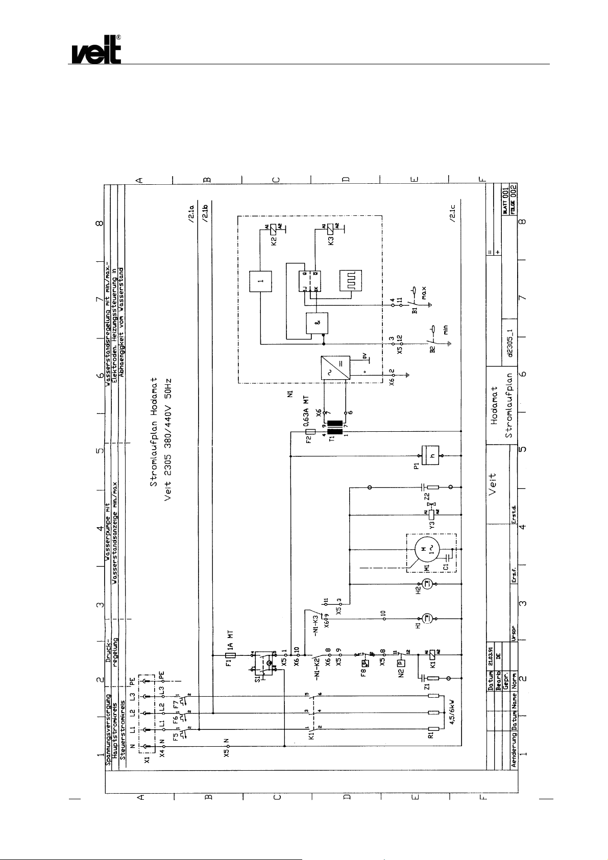
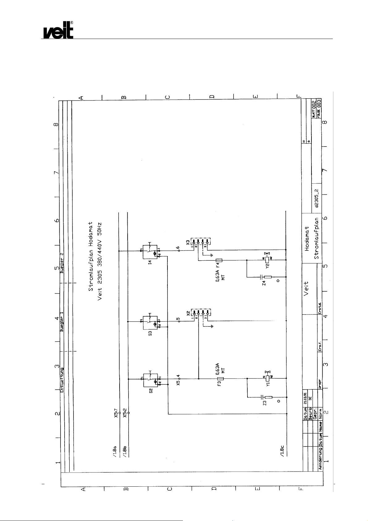
8 Schaltpläne / Circuit Diagrams
Water level control with min./max.
Electrodes heating control depending
On water level
Water pump with
Water level indicator min./max.
Pressure
control
Voltage supply
Main circuit
Control circuit
Flow Diagram Hodamat
Dampferzeuger Hodamat VEIT 2305
VEIT 2305 Hodamat Steam Generator
X5/24
12
11
X5/22
X5/23
X5/21
01.10.2008 24
Air-vent Iron 1 Iron 2
Dampferzeuger Hodamat VEIT 2305
VEIT 2305 Hodamat Steam Generator
X5/28
X5/27
Flow Circuit Hodamat
X5/26
X5/25
01.10.2008 25

min
max
(black)
(white)
Movable panel
casing
Boiler shell
Boiler chamber switch box front panel
Dampferzeuger Hodamat VEIT 2305
VEIT 2305 Hodamat Steam Generator
Siehe Seite: 28
see page: 28
Connection Plan
01.10.2008 26

Dampferzeuger Hodamat VEIT 2305
VEIT 2305 Hodamat Steam Generator
Siehe Seite: 28
see page: 28
Wiring Plan
01.10.2008 27

Dampferzeuger Hodamat VEIT 2305
VEIT 2305 Hodamat Steam Generator
9 Aufbau der Ergänzung von Klemmleiste X5 / Assembling of complement strip
terminal X5
01.10.2008 28

Dampferzeuger Hodamat VEIT 2305
VEIT 2305 Hodamat Steam Generator
10 Service- und Pflegeanleitung / Service and Maintenance Instructions
Gültig für alle VEIT-Dampferzeuger mit automatischer Befüllung
(Elektrik). Diese Service- und Pflegeanleitung soll dm
Betriebstechniker im Sinne von „Was ist wenn ...?“
auftretende Fehler zu finden, die auf falsche Bedienung oder
normalen Verschleiß zurückzuführen sind.
helfen, evtl.
Befüllung des Kessels
1. Pumpe arbeitet, fördert aber kein Wasser in den Kessel:
• Sieb am Ansaugschlauch ist verstopft - reinigen.
• Befüllmagnetventil öffnet sich nicht - wenn elektrischen
Anschlussprüfung in Ordnung Magnetventil
austauschen.
• Rückschlagventil öffnet nicht - Rückschlagventil
austauschen.
• Wasserzuführungsleitung zum Kessel ist verstopft
(Kalkbildung) - Leitung freimachen.
• Pumpe arbeitet, fördert aber kein Wasser, weil sich in
der Zuleitung eine Luftblase befindet.
Schadensbehebung:
Entlüftungshahn.
2. Bei Inbetriebnahme des Gerätes nach längerer
Arbeitsunterbrechung steigt der Druck zu schnell.
Fehler 1:
Fehler 2:
Heizung
Die Heizung schaltet nur ein, wenn der minimale Wasserstand
(NW) erreicht wurde. Sie schaltet bei folgenden Defekten nicht
ein:
1. Wie bekannt benötigt der Dampferzeuger 380V-
2. Wasserstandselektroden sind verschmutzt, reinigen,
3. Schaltschützkontakte sind verbrannt.
4. Schaltschützspule ist verbrannt.
5. Die elektrische Leitung vom Schaltschütz zur Heizung
6. Heizkörper ist defekt. (Durchgangsmessung ist nur
7. Brücken am Heizkörper sind verschmort.
Bügeleisen geben Wasser, Sicherheitsventil
spricht an.
Der Kessel hat sich durch Vakuumbildung im
Kessel selbst befüllt.
Ursache:
Behebung:
Sicherheitsventil spricht an, der Druck steigt
über zulässigen Wert an, da Luft im Kessel ist.
Behebung:
Dreiphasenstrom (Drehstrom). Es muss darauf
geachtet werden, dass alle drei Phasen im Gerät
ankommen.
evtl. erneuern.
ist defekt.
möglich, wenn vorher die Brücken entfernt worden
sind.)
Pumpe entlüften, durch
Magnetventil ist undicht.
Wasser ablassen, evtl.
Magnetventilbefüllgruppe
erneuern.
Kontakter am Bügeleisen
betätigen bis Dampf austritt.
Applicable to all VEIT steam generators featuring automatic
refilling (electronic unit). These Servicing Instructions are
intended to help, on the 'what if' principle, your in-house
technician to find any defect due to operator error or normal wear
and tear.
Boiler Filling
1. Pump works without delivering water into the boiler:
• Strainer on suction hose clogged - clean.
• Filling solenoid fails to open: check electrical
connections. If okay, replace solenoid valve.
• Check valve fails to open - replace valve.
• Pipe supplying water to the boiler clogged (scaling) –
clean pipe.
• Pump works without delivering water because there is
an air bubble within the feed line.
Action:
vent pump through venting connection.
2. Upon starting the unit after prolonged downtime, pressure
increases too fast:
Malfunction 1:
Malfunction 2:
Heating Unit
The heating system will be switched on only if there is the
minimum water level. It will not switch on if there is one of the
following defects:
1. As is generally known, the steam generators require
three-phase 380V current. Check whether all three
phases are applied to the unit.
2. Water level electrodes are soiled, clean them. Replace
them; if necessary.
3. Contactor terminals burned.
4. Contactor coil burned.
5. Supply line connecting contactor and heating unit
defective.
6. Heating element defective (continuity testing only after
prior removal of bridges).
7. Heating element bridges charred.
Iron dispenses water, safety valve
reacts. Due to vacuum formation
within it, boiler filled automatically.
Solenoid valve leaky.
Cause:
Drain water; if necessary,
Action:
Safety valve reacts. Pressure increases
beyond admissible value since there is
air within the boiler.
Action:
replace solenoid valve /
filling group.
Actuate press contact until
steam appears.
01.10.2008 29

Unregelmäßige Befüllung
Elektroden sind verkalkt.
Funktionieren diese nach eingehender Säuberung immer noch
nicht, müssen die Elektroden erneuert werden.
Die Elektroden sind mit einem normalen Messgerät nicht
messbar.
Druckabfall im Kessel
1. Elektroden sind defekt (wie beschrieben).
2. Kesselheizung defekt (wie beschrieben).
3. Zuleitung defekt (wie beschrieben).
4. Druckwächter hat sich verstellt.
5. Druckdifferenz im Druckwächter hat sich verstellt.
6. Befüllung nicht in Ordnung (wie beschrieben)
7. Ablasshahn ist undicht.
8. Überdruckventil öffnet sicht zu früh.
9. Druckabfall ist in Wirklichkeit nicht vorhanden, da
Manometer wegen Defekt nicht richtig anzeigt.
10. Heatstop ist defekt (diese Funktion zuerst überprüfen).
Manometer
Manometer zeigt zu hohen Druckanstieg an:
1. Druckwächtermaximaldruck ist zu hoch eingestellt.
2. Versorgungsleitung zum Kessel ist verstopft. Statt
Dampf drückt Wasser auf das Manometer.
3. Manometerrohrleitung ist verschmutzt.
Magnetventil
Magnetventil arbeitet nicht:
1. Kabelbruch an der Magnetspule.
2. Magnetspule defekt.
3. Plunger klemmt im Plungerrohr.
4. Plungerfeder ist defekt.
5. Mikroschalter am Bügeleisen ist defekt.
6. Elektroleitung vom Bügeleisen zum Kessel ist defekt.
7. T-Stecker am Bügeleisenkabel ist defekt.
8. T-Steckdose am Kessel ist defekt.
9. Kesselstromzuführung ist defekt.
Dampferzeuger Hodamat VEIT 2305
VEIT 2305 Hodamat Steam Generator
Irregular Filling
Electrodes scale-covered.
If, they still fail to operate after careful cleaning, replace them.
Electrodes cannot be measured using standard measuring
equipment
Loss of Boiler Pressure
1. Electrodes defective (as described)
2. Boiler heating unit defective (as described)
3. Feed line defective (as described)
4. Pressure controller misaligned
5. Pressure controller differential misaligned
6. Incorrect filling (as described)
7. Drain cock leaky
8. Overpressure valve opens prematurely
9. No real pressure loss: pressure gauge displays
incorrectly, as it is defective
10. Heatstop defective (start by checking this function)
Pressure Gauge
Pressure indicated by gauge too high:
1. Maximum gauge pressure set too high
2. Boiler feed line clogged: gauge subject to water
instead of steam pressure
3. Gauge tubing dirty
Solenoid Valves
Fails to operate:
1. Coil cable broken
2. Coil defect
3. Plunger jammed within tube.
4. Plunger spring defective.
5. Microswitch on iron defective
6. Cable linking iron and boiler defective
7. T-plug on iron cable defective
8. T-socket on boiler defective
9. Boiler power supply defective
01.10.2008 30

Elektronik
Die Elektronik ist das Herz des VEIT-Dampferzeugers.
Aufbau und Konstruktion sind so abgestimmt, dass die
Steuerung sämtlicher Funktionen bei Funktionstüchtigkeit der
Elektronik gewährleistet ist.
Voraussetzung für die Funktion ist das reibungslose Arbeiten
aller bisher beschriebenen Vorgänge. Die Elektronik ist
nochmals durch eine Feinsicherung gegen Stromstöße und
Schwankungen abgesichert. Diese Feinsicherung darf nicht
durch Draht überbrückt werden. Die Elektronik kann in der Regel
durch die Funktionstüchtigkeit eines anderen Teils nicht
beschädigt werden.
Ein Auswechseln ist nur durch natürlichen Verschleiß und bei
grober unsachgemäßer Behandlung erforderlich, wie z.B. durch
selbstverschuldeten Kurzschluss der Stromanlage infolge
Fehlschaltung am Klemmbrett.
Überhitzungsschutz
Sicherheitstemperaturbegrenzer
Als Übertemperatursicherung wird ein TÜV-geprüfter
Sicherheitstemperaturbegrenzer verwendet. Der Messfühler des
Begrenzers befindet sich in einer Tauchhülse über den
Heizungen. Der Begrenzer unterbricht die Stromzufuhr zu den
Heizpartronen bei Erreichen einer Grenztemperatur von 235°C.
Nach der Unterbrechung muss unbedingt die Ursache der
Unterbrechung gesucht werden. Erst danach darf der Begrenzer
zurückgestellt werden.
Das Sicherheitssystem der VEIT-Dampferzeuger umfasst
1. Sicherheitsventil (bauteilgeprüft)
2. Edelstahlheizpatrone
3. Sicherheitstemperaturbegrenzer (Überhitzungsschutz,
bauteilgeprüft)
4. Druckregler (Pressostat)
5. Wasserstandselektronik mit Messelektroden und
Sicherung
6. Wasserspiegel immer über dem Scheitel der
Heizpatrone (Auslaufsicherung).
7. Befüllgruppe mit Elektromagnetventil und
Rückschlagventil
8. Röhrenfeder Manometer
9. VDE getestetes elektrisches Steuerungssystem
Dampferzeuger Hodamat VEIT 2305
VEIT 2305 Hodamat Steam Generator
Electronics
The electronic system is the heart of any VEIT steam generator.
It is designed so as to guarantee proper control of all functions
as long as it is operative.
Proper function depends upon perfect operation of all processes
described so far. Additionally, the electronic unit is protected
against power surges and fluctuations by means of a fine-wire
fuse, which must never be bridged. Normally, the electronic unit
cannot be damaged by the function of any other component.
Replacement will only be necessary after normal wear and tear
or in the event of grossly improper handling such as negligent
shorting of the power supply unit due to erroneous connections
at the terminal block.
Overheat protection
Safety heat-stop
A TÜV-tested safety heat-stop is used as a fuse for overheating.
The sensor of the heat-stop is in a tube over the heating
elements. The heat-stop interrupts the current supply to the
heating cartridges the temperature has risen to 235°C. After the
interruption the cause must be found immediately and only then
may the heat-stop be reset.
The Safety System of any VEIT Steam Generator comprises
1. Safety valve (type certified)
2. Stainless steel heating cartridge
3. Safety temperature limiter (overheating protection,
type certified)
4. Temperature controller (Pressostat)
5. Level control electronics featuring electrodes and fuse
6. Water level invariably above top of heating cartridge
7. Filling group featuring solenoid valve and check valve
8. Pressure capsule gauge
9. VDE-tested electrical control system
01.10.2008 31
Dampferzeuger Hodamat VEIT 2305
VEIT 2305 Hodamat Steam Generator
11 EG-Konformitätserklärung / EC Declaration of Conformity
01.10.2008 32
 Loading...