

Veit 2381 Steam Station 40 kW, 2381 Steam Station 50 kW, 2381 Steam Station 60 kW Operating Instructions Manual
Page 1
TD2381 _i20140828.doc
Betriebsanleitung
Operating Instructions
Dampfstation / Steam Station 40 kW
Dampfstation / Steam Station 50 kW
Dampfstation / Steam Station 60 kW
VEIT 2381
Pressing for Excellence
Page 2
Dampfstation VEIT 2381 40 kW / 50 kW / 60 kW
VEIT 2381 Steam Station 40 kW / 50 kW / 60 kW
28.08.2014 2
VEIT GmbH
Justus-von-Liebig-Str. 15
D - 86899 Landsberg am Lech
Germany
Phone +49 (81 91) 479 0
Fax +49 (81 91) 479 149
www.veit-group.com
Service Hotline
Germany: +49 (81 91) 479 133
Europe: +49 (81 91) 479 252
America: +1 (770) 868 8060
Asia: +852 2111 9795
Ersatzteile/Spare parts
Vertrieb/Sales +49 (8191) 479 176
Vertrieb Textilpflege/ +49 (8191) 479 129
Sales Textile care
Page 3

Dampfstation VEIT 2381 40 kW / 50 kW / 60 kW
VEIT 2381 Steam Station 40 kW / 50 kW / 60 kW
28.08.2014 3
Inhaltsverzeichnis / Table of Contents:
1 Betriebsanleitung / Operating Instructions 4
1.1 Warnhinweise / Warnings 4
1.2 Technische Daten / Technical Data 5
1.3 Vorschriften / Regulations 9
1.4 Bedienelemente / Operating Elements 10
1.5 Aufstellung und Anschluss / Installation and Connection 10
1.6 Arbeitsweise und Sicherheitseinrichtungen / Mode of Operation and Safety Devices 14
1.6.1 Arbeitsweise / Mode of Operation 14
1.6.2 Sicherheitseinrichtungen / Safety Devices 14
1.7 Inbetriebnahme / Commissioning and Start-up 15
2 Betrieb / Operating 16
2.1 Abschlämmen / Blow-down 16
3 Auflistung der Leistungen / Listing of Power 17
4 Störungsbeistand / Troubleshooting 18
5 Prüf- und Wartungsarbeiten / Inspection and
Maintenance Work 19
5.1 Wartungsplan / Maintenance Schedule 20
6 Schaltpläne / Circuit Diagrams 22
7 Ersatzteile / Spare Parts 24
8 Zeichnung der Anschlüsse / Drawing of the
Connections 29
9 Bescheinigung / Certificate 30
10 EG-Konformitätserklärung / EC Declaration of
Conformity 32
11 Zertifikat / TÜV Certificate 33
Page 4

Dampfstation VEIT 2381 40 kW / 50 kW / 60 kW
VEIT 2381 Steam Station 40 kW / 50 kW / 60 kW
28.08.2014 4
1 Betriebsanleitung / Operating Instructions
1.1 Warnhinweise / Warnings
STÖRUNGEN AN DER ELEKTRISCHEN ANLAGE DÜRFEN
NUR DURCH ELEKTROFACHKRÄFTE BEHOBEN WERDEN.
VOR ÖFFNEN DES GERÄTES HAUPTSCHALTER IN
STELLUNG „0“ BRINGEN UND GEGEBENENFALLS
ABSCHLIESSEN.
BEVOR DER DAMPFERZEUGER ÜBER DEN
HAUPTSCHALTER ABGESCHALTET WIRD, MÜSSEN DIE
HEIZUNGSSTUFENSCHALTER AUSGESCHALTET WERDEN
=> AUSNAHME: NOTFALL
IM NOTFALL KANN DER DAMPFERZEUGER ÜBER DEN
HAUTPSCHALTER DIREKT STILLGESETZT WERDEN!
BEI LÄNGEREN BETRIEBSPAUSEN ABSPERRHAHN DER
SPEISEWASSERZUFUHR SCHLIESSEN. GEFAHR VON
WASSERSCHÄDEN!
DAS GERÄT VOR FROST SCHÜTZEN.
ELECTRICAL FAULTS MUST ONLY BE REPAIRED BY
AUTHORIZED PERSONNEL.
BEFORE OPENING THE UNIT, TURN THE MAIN SWITCH TO
POSITION "0" AND LOCK, IF NECESSARY.
BEFORE THE STEAM GENERATOR IS SWITCHED OFF VIA
MAIN SWITCH, THE SWITCHES FOR THE HEATING
ELEMENTS (HEATING POWER) MUST BE SWITCHED OFF
=> EXCEPTION: IN CASE OF AN EMERGENCY
IN EMERGENCY CASE, THE STEAM GENERATOR CAN BE
DIRECTLY SWITCHED OFF VIA MAIN SWITCH!
DURING A LONGER OPERATIONBREAK CLOSE STOPCOCK
OF THE FEED WATER SUPPLY. RISK OF WATER DAMAGE!
PROTECT THE UNIT FROM FROST.
Page 5
Dampfstation VEIT 2381 40 kW / 50 kW / 60 kW
VEIT 2381 Steam Station 40 kW / 50 kW / 60 kW
28.08.2014 5
1.2 Technische Daten / Technical Data
max. 10 bar
Page 6

Dampfstation VEIT 2381 40 kW / 50 kW / 60 kW
VEIT 2381 Steam Station 40 kW / 50 kW / 60 kW
28.08.2014 6
Modell
VEIT 2381
40 kW
VEIT 2381
50 kW
VEIT 2381
60 kW
Artikelnummer
1238110020 1238110030 1238110040
Elektrischer
Anschluss
Volt 400 400 400
Hz 50 50 50
kW 40 50 60
A
Netzseitige
Absicherung
A
Wasseranschluss Zoll 3/8
min. 3 bar
max. 10 bar
3/8
min. 3 bar
max. 10 bar
3/8
min. 3 bar
max. 10 bar
Dampfanschluss Zoll 3/4 3/4 3/4
Betriebsdruck bar 6,0 6,0 6,0
Einstellbar auf bar 7,0 7,0 7,0
Dampfmenge kg/h 55 68 82
Kondensatanschluss Zoll 1/2 1/2 1/2
Abwasseranschluss Zoll 3/4 3/4 3/4
Wrasenausgang Zoll 1 1/4 1 1/4 1 1/4
Dampfverbraucher Bügler / Finisher / Sonstiges
Bügler / Finisher /
Unterdampftisch
Bügler / Finisher /
Unterdampftisch
Maße und Gewichte
Breite mm 1074 1074 1074
Höhe mm 956 956 956
Tiefe mm 770 770 770
Gewicht kg 340 (unbefüllt)
523 (befüllt)
340 (unbefüllt)
523 (befüllt)
340 (unbefüllt)
523 (befüllt)
Optionen Verbindungsset (Tandembetrieb) Art.-Nr. 2238120000
Erhöhungsset 30 cm (4 Stück) Art.-Nr. 2238120010
Page 7

Dampfstation VEIT 2381 40 kW / 50 kW / 60 kW
VEIT 2381 Steam Station 40 kW / 50 kW / 60 kW
28.08.2014 7
Model VEIT 2381
40 kW
VEIT 2381
50 kW
VEIT 2381
60 kW
Article number 1238110020 1238110030 1238110040
Electrical
Connection
Volt 400 400 400
Hz 50 50 50
kW 40 50 60
A
Fuse protection A
Water connection inch 3/8
min. 3 bar
max. 10 bar
3/8
min. 3 bar
max. 10 bar
3/8
min. 3 bar
max. 10 bar
Steam connection inch 3/4 3/4 3/4
Working pressure bar 6,0 6,0 6,0
rated working
pressure
bar 7,0 7,0 7,0
Steam output kg/h 55 68 82
Condensate
connection
inch 1/2 1/2 1/2
Waste water
connection
inch 3/4 3/4 3/4
Exhaust steam inch 1 1/4 1 1/4 1 1/4
Steam user Irons / Finishers / Others Irons / Finishers / Up-
Steam Tables
Irons / Finishers / Up-Steam
Tables
Dimensions and
weight
Width mm /
inch
1074 / 42 1074 / 42 1074 / 42
Height mm /
inch
956 / 37.5 956 / 37.5 956 / 37.5
Depth mm /
inch
770 / 30 770 / 30 770 / 30
Weight kg / lbs 340 / 749 (empty)
523 / 1152 (filled)
340 / 749 (empty)
523 / 1152 (filled)
340 / 749 (empty)
523 / 1152 (filled)
Options Connection Set (Tandem Processing) Art.-No. 2238120000
Elevation Set 30 cm (4 pieces) Art.-No. 2238120010
Page 8

Dampfstation VEIT 2381 40 kW / 50 kW / 60 kW
VEIT 2381 Steam Station 40 kW / 50 kW / 60 kW
28.08.2014 8
Elektrischer Anschluss Electrical connection siehe Typenschild See machine-plate
Elektrischer Anschlusswert
Connected load kW 40 50
60
Heizleistung 1-, 2- oder 3stufig
Heating power 1-, 2- or 3stage
kW 20+20 10+20+20 20+20+20
Heizfläche Heating surface dm² 37,8 56,6 56,6
Sattdampfleistung Saturated steam power kg/h 55 68 82
Zulässiger
Betriebsüberdruck
Admissible working
overpressure
bar 8 8 8
Eingestellter Betriebsdruck Adjusted working pressure bar 6 6 6
Wasserinhalt NW Water content min. water
level
l 48 48 48
Kesselvolumen Boiler volume l 75 75 75
Speisewassertemperatur
max.
Feedwater temperature
max.
°C 100 100 100
Abschlämmbehälter Blow-down tank drucklos
without
pressure
Anschlüsse: Connections:
Dampf Steam Kugelhahn ¾“ Ball valve ¾“
Kondensat Condensate ½“ Innengewinde ½“ internal screw thread
Wasser Water 3/8" Innengewinde
max. 10 bar
3/8“ internal screw thread
max. 10 bar
Überlauf
Speisewassergefäß
Overflow feedwater
tank
3/4" Innengewinde 3/4" internal screw thread
Überlauf
Abschlämmbehälter
Overflow blow-
down tank
1 ¼” Innengewinde 1 ¼” internal screw thread
Abmessungen: Dimensions:
Breite Width mm 1080
Tiefe Depth mm 780
Höhe Height mm 970
Baujahr: Year of construction: siehe Typenschild See machine-plate
Page 9

Dampfstation VEIT 2381 40 kW / 50 kW / 60 kW
VEIT 2381 Steam Station 40 kW / 50 kW / 60 kW
28.08.2014 9
1.3 Vorschriften / Regulations
Die VEIT 2381 Dampfstation mit elektrischer
Widerstandsheizung wird zur Erzeugung von Wasserdampf für
industrielle und gewerbliche Zwecke verwendet.
Der Dampferzeuger entspricht der Kategorie III der DruckgeräteRichtlinie (97/23/EG) und wurde zertifiziert von der
Zertifizierungsstelle TÜV SÜD Industrie Service GmbH –
CE0036 - nach DGRL in Verbindung mit der TRD 802.
In der Dokumententasche, die außen am Gerät angebracht ist,
befinden sich das Zertifikat über die Wasserdruckprüfung und
die Bescheinigung über die ordnungsgemäße Installation der
Dampfkesselanlage.
Die elektrische Ausrüstung des Dampfkessels entspricht den
einschlägigen VDE-Bestimmungen. Der örtliche Anschluss hat
nach den technischen Anschlussbestimmungen (TAB) des
zuständigen Elektroversorgungsunternehmens zu erfolgen.
Inbetriebnahme in Deutschland:
1. Der Dampferzeuger darf nur von einem zugelassenen
Elektrofachmann unter Beachtung der VDE- und örtlichen
Vorschriften angeschlossen werden.
2. Für diesen Dampferzeuger 2381 sind "wiederkehrende
Prüfungen" durch eine „befähigte Person“ z.B. der VEITKundendienst, erforderlich. Dazu werden die
Wartungsarbeiten gemäß dem Wartungsplan durchgeführt
und abgezeichnet.
Wiederkehrende Prüfungen durch eine „zugelassene
Überwachungsstelle“ (z.B. TÜV) sind nicht erforderlich, da
das Produkt von Druck mal Volumen unter 1000 bar x Liter
liegt. (§ 15 Betriebssicherheitsverordnung).
3. Spätestens 6 Monate nach der Inbetriebnahme dieses
Dampferzeugers muss der Betreiber den beigefügten
Wartungsplan „Merkblatt MB 2381-005“ mit den
technischen Daten und den Prüffristen dem
Gewerbeaufsichtsamt zuschicken. (Ebenfalls § 15 der
Betriebssicherheitsverordnung).
Bemerkung:
Die Prüfung vor Inbetriebnahme gem. § 14 BetrSichV ist nicht
notwendig, da an einem Dampferzeuger dieses Typs 2381 eine
Prüfung vor Inbetriebnahme durch eine zugelassene
Überwachungsstelle ohne Bezug auf einen Aufstellungsort
durchgeführt wurde.
Die Dampferzeuger des Typs 2381 sind somit
„Verwendungsfertige Aggregate“ gemäß Anhang 5 Nummer 25
der BetrSichV.
Für übrige Länder:
Hier sind die jeweiligen Vorschriften einzuhalten.
The VEIT 2381 steam station with electrical resistance heating is
used to produce water steam for industrial use.
The built-in steam generator complies with category III of the
pressure device directive (97/23/EC) and was certified by the
certification authority TÜV SÜD Industrie Service GmbH –
CE0036 – according to PED in connection with TRD 802.
In the document box, which is attached at the side of the unit,
you will find the certificate for the water pressure test and the
certificate of the proper installation of the steam boiler unit.
The electrical equipment of the steam boiler meets the relevant
VDE-regulations. The local connection must be made according
to the technical regulations of the responsible electric supplier.
For other countries
Here the respective regulations must be obeyed.
Page 10
Dampfstation VEIT 2381 40 kW / 50 kW / 60 kW
VEIT 2381 Steam Station 40 kW / 50 kW / 60 kW
28.08.2014 10
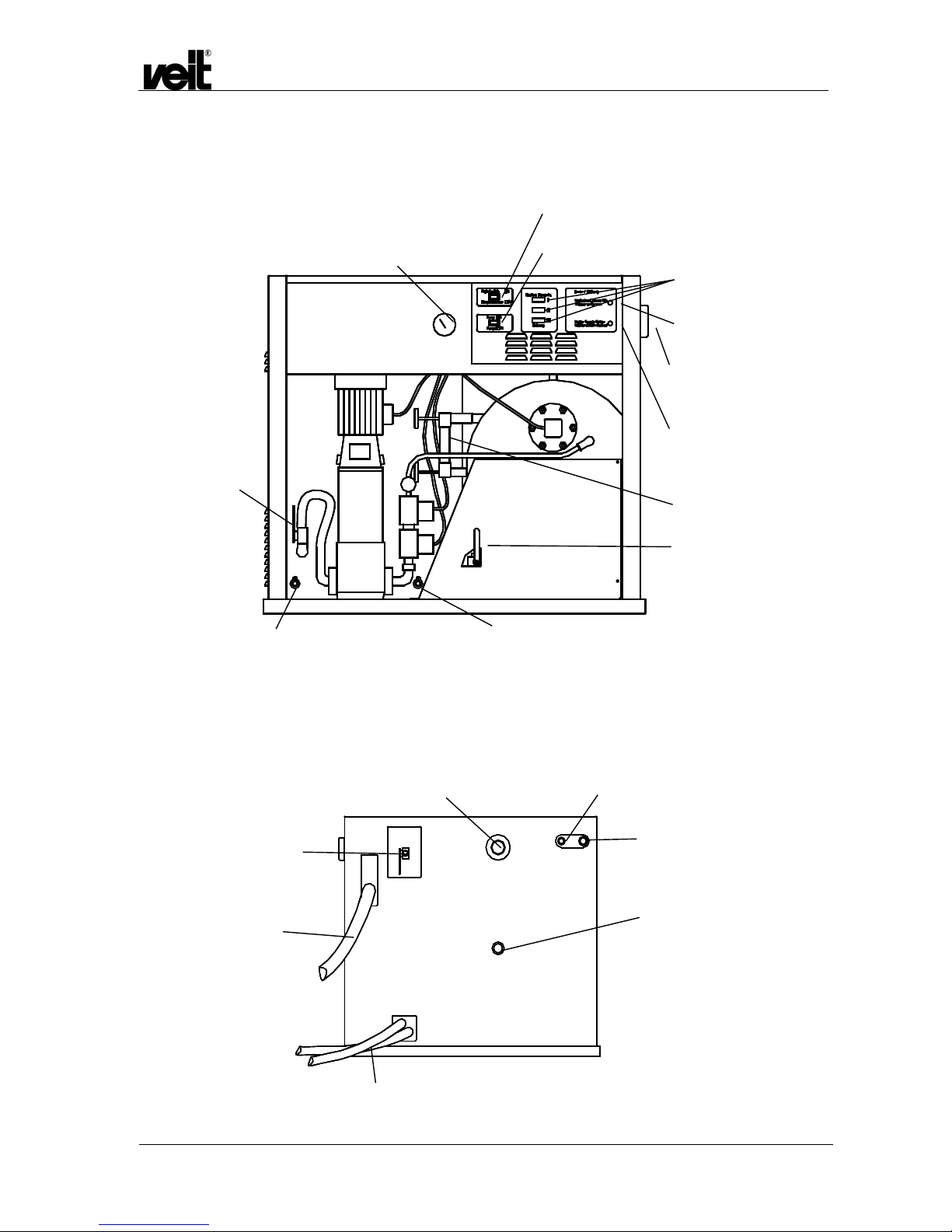
1.4 Bedienelemente / Operating Elements
1.5 Aufstellung und Anschluss / Installation and Connection
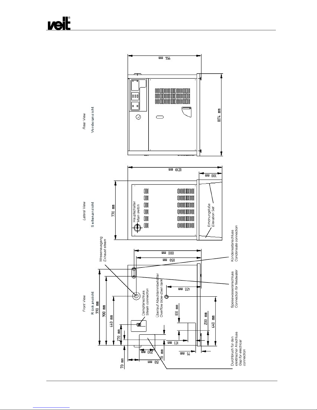
Anschlussmaße siehe Kapitel 8 Zeichnung und Anschlüsse. Connection dimensions see chapter 8 Drawing of the
Connections.
Ansicht von hinten
View from the back
Manometer /
Manometer
Kontroll-Lampe weiß: Hauptschalter “EIN” /
control lamp white: main switch “ON”
Kontroll-Lampe rot: Pumpe läuft /
control lamp red: pump is running
Kugelhahn
Speisewasserleitung /
ball valve feedwater
line
Ablasshahn Speisewasserbehälter /
Outlet cock feedwater tank
Ablasshahn Abschlämmbehälter /
outlet cock blow-down tank
Abschlämmhahn /
Blow-down cock
Wasserstands-Schauglas /
Water level inspection glass
Hauptschalter /
Main switch
Signalleuchte rot: Pumpenlaufzeit
überschritten /
Signal lamp red: operating time of
pump is exceeded
Heizungsschalter /
Switch for heating
Signalleuchte rot: Wasser zu niedrig/
Signal lamp red: water too low
Speisewasser 3/8“ Muffe/
Water supply 3/8“ bushing
Entleerung Abschlämm-/Speisewasserbehälter /
Outflow blow-down and feedwater tank
Überlauf Abschlämmbehälter ¾“ /
Overflow blow-down tank ¾”
Kondensat ½“ /
Condensate ½“
Wrasenausgang 1 ¼“ /
Exhaust steam 1 ¼“
Dampfaustritt Kugelhahn ¾“/
Steam exit ball valve ¾“
Elektr. Anschlusskabel /
Electr. connection cable
Page 11

Dampfstation VEIT 2381 40 kW / 50 kW / 60 kW
VEIT 2381 Steam Station 40 kW / 50 kW / 60 kW
28.08.2014 11
Die Dampfstation VEIT 2381 wird als anschlussfertiges Gerät
geliefert. Sie ist mit allen erforderlichen Sicherheits- und
Bedienvorrichtungen ausgerüstet. Das Speisewassergefäß und
der Abschlämmbehälter sind im selben Gehäuse untergebracht
und fest mit dem Kessel verbunden.
Die Dampfstation muss an einem Platz installiert werden, an
dem eine einwandfreie Bedienung und Zugänglichkeit zu allen
Armaturen gewährleistet ist.
Die Anschlussleitungen (Elektrokabel, Kondensat,
Speisewasser) sind so zu verlegen, dass sie keine Stolperfallen
darstellen.
Der Dampferzeuger ist für den Betrieb mit normalem oder
enthärtetem Leitungswasser geeignet. Bei Zusatz von
Chemikalien übernimmt VEIT keine Haftung für Funktion und
Sicherheit des Geräts.
Folgende Anschlüsse sind erforderlich:
• Dampfaustritt
Kugelhahn ¾“ bereits installiert
• Speisewasseranschluss:
Muffe 3/8“ auf der Rückseite des Gerätes.
Achtung: Für die druckführende Leitung zum
Speisewasserbehälter wird eine starre Verrohrung
empfohlen. Für das letzte Stück zum Gerät kann auch ein
Panzerschlauch verwendet werden. Wir empfehlen 1 m,
maximal jedoch 3 m Panzerschlauch. Der Panzerschlauch
muss für den maximalen Leitungsdruck geeignet sein.
Keinesfalls dürfen flexible, ungeschützte Schläuche und
Schlauchklemmen verwendet werden.
Am Übergang von der starren Verrohrung zum
Panzerschlauch ist ein Absperrhahn vorzusehen.
Die Wasserhärte darf 4°dH nicht überschreiten.
Bei höheren Wasserhärten empfiehlt sich die Verwendung
einer Wasserenthärtungsanlage (z.B. VEIT 3307).
• Kondensatanschluss:
Die Kondensatleitung muss an den Kondensatstutzen des
Speisewasserbehälters angeschlossen werden (Muffe1/2“).
• Überlauf Abschlämmbehälter:
Am Ende des Abschlämmvorgangs treten etwa 50 Liter
heißes Wasser (bis 80°C) aus dem Abschlämmbehälter aus.
Dafür in die ¾“ Muffe eine Schlauchtülle schrauben und
einen Schlauch mit einer Schelle sicher befestigen.
Der Schlauch muss mindestens ¾“ Querschnitt haben und
bis 100°C temperaturfest sein. Wir empfehlen den ¾“
Schlauch Art.-Nr. 9270530460.
Der Schlauch muss knickfrei verlegt und im Abwasserablauf
sicher befestigt werden. Der ungehinderte Abfluss muss
gewährleistet sein.
• Wrasenausgang aus dem Abschlämmbehälter:
Muffe 1 ¼“ auf der Rückseite des Gerätes, ein 90°-Winkel ist
dem Gerät beigelegt. Diese Leitung darf in ihrem Querschnitt
nicht reduziert werden.
Achtung: Es muss gewährleistet sein, dass sich im
Abflusssystem unter keinen Umständen ein Druck aufbauen
kann. Keinesfalls darf der Überlauf aus dem
Abschlämmbehälter (3/4“) mit dem Wrasenausgang (1 ¼“)
verbunden werden!
The VEIT 2381 steam station is ready for connection when it is
delivered. It is equipped with all necessary safety and operating
devices. The feedwater tank and the blow-down tank are
assembled in the same casing and are directly connected to the
boiler.
The steam station must be installed at a place where it can be
operated properly and with easy access to all mountings.
The connection lines (electro cable, condensate, feedwater)
must be laid that way that these lines cannot be tripped over.
The steam generator is suited for operation with normal or
softened tap water. If other chemicals are added, VEIT bears no
responsibility for any resulting damage and for the function and
safety of the machine.
The following connections are necessary:
• Steam Exit
ball valve ¾” already installed
• Feedwater connection:
Bushing 3/8” at the backside of the machine.
Attention: A fixed piping is recommended for the pipe with
pressure which goes to the feed water tank. For the last
section to the machine a armoured tube can also be used.
We recommend 1 m, but max. 3 m armoured tube. The
armoured tube must be suitable for the maximal pressure of
the pipe. Flexible or unprotected hoses and hose clips may
not be used.
At the transition of fixing pipe to the armoured tube a
stopcock should be planned.
The water hardness must not exceed 4° dH (German
hardness).
If the water hardness is higher, a water-softening unit (for
example VEIT 3307) is recommended.
• Condensate connection:
The condensate line must be connected to the condensate
plinth of the feedwater tank (bushing 1/2”).
• Overflow blow-down tank:
At the end of the blow-down operation about 50 litre of hot
water (up to 80°C) will leak from the blow-
down tank.
Screw in the ¾” bushing a hose nozzle and fit the hose
safely with a clip.
The hose must have a cross section of min. ¾“ and it must
be heatp
roof up to 100°C. We recommend the hose ¾”
Art. Nr. 9270530020.
The hose must be installed without a break and it must be
fit safely at the waste water drain. Free drainage must be
ensured.
• Exhaust steam of blow-down tank:
Bushing 1 ¼” at the back side of the machine, a angle 90 ° is
enclosed to the unit. This pipe may not be reduced in its
cross-section.
Attention: It must be ensured that, under no circumstances,
no pressure can be built up in the drain system.
Never connect the overflow of the blow-down tank (3/4“)
with the exhaust steam (1 ¼“).
Page 12

Dampfstation VEIT 2381 40 kW / 50 kW / 60 kW
VEIT 2381 Steam Station 40 kW / 50 kW / 60 kW
28.08.2014 12
• Kugelhahn für das Entleeren des
Speisewasserbehälters:
Er befindet sich links unten am Speisewasserbehälter und
wird mit einem ½“-Gummischlauch an den
Abwasseranschluss angeschlossen. Dieser wird nach hinten
hinausgeführt. Zum Öffnen des Kugelhahns den
beiliegenden Deckel verwenden.
• Kugelhahn für das Entleeren des Abschlämmbehälters:
Er befindet sich rechts unten am Abschlämmbehälter und
wird mit einem ½“-Gummischlauch an den
Abwasseranschluss angeschlossen. Zum Öffnen des
Kugelhahns den beiliegenden Deckel verwenden.
Für die oben genannten Anschlüsse, siehe Kapitel 8
Zeichnung der Anschlüsse.
• Elektrischer Anschluss:
Als Anschlusskabel empfehlen wir eine schwere
Gummischlauchleitung H 07 RN-F. Das Kabel wird durch die
Einführungstülle M50 in den Elektrokasten geführt und an
dem Hauptschalter/Eingangsklemmen angeschlossen.
WICHTIG!
Das Kabel mit der passenden Schelle an der
vorgesehenen Stelle am Rahmen fixieren
(Zugentlastung). Auf die Klemmstellen im Elektrokasten
dürfen keine Zugkräfte wirken.
Bitte Beachten:
Kabeleinführung muss so ausgeführt sein, dass kein
Dampf und kein Wasser ins Innere des Elektrokastens
gelangen kann.
Der Elektroanschluss darf nur von einem zugelassenen
Elektrofachmann unter Beachtung der VDE- und
örtlichen Vorschriften ausgeführt werden.
Beim Anschließen der Dampfstation muss das
Hauptschalterkabel nachgezogen werden, dazu muss
beiliegendes Merkblatt 2381-001 beachtet werden.
• Schwimmerschalter anbauen
Für den Transport wurde der schwarze Kunststoffschalter
des Schwimmers abgenommen.
Für die Montage die vordere Verkleidung des
Dampferzeugers abnehmen. Das Massekabel abziehen.
Die schwarze Kunststoffabdeckung vom Schalter
abschrauben.
Mit Hilfe der beiliegenden Innensechskantschrauben wird
der Schalter auf den Messingträger geschraubt. Die
Einstellschraube, die von der Wippe betätigt wird, ist
werkseitig voreingestellt und darf nicht verstellt werden.
Hinweis: Ersatzschalter sind werkseitig voreingestellt. Der
untere Mikroschalter schaltet dann, wenn der
Wasserspiegel im Schauglas gerade noch gesehen werden
kann.
Anschließend die schwarze Kunststoffabdeckung
montieren, dabei das elektrische Kabel nicht verletzen.
Die vordere Verkleidung samt aufgestecktem Massekabel
wieder montieren.
• Ball valve for emptying of feedwater tank:
It is on the left bottom side at the feedwater tank and is
connected with a ½” rubber hose to the drain. This hose is
leaded out to the back. Use the enclosed cap for opening the
ball valve.
• Ball valve for emptying of blow-down tank:
It is on the right bottom side of the blow-down tank and is
connected with a ½” rubber hose to the drain. Use the
enclosed cap for opening the ball valve.
For the above mentioned connections see also chapter 8
drawing of the connections.
• Electrical connection:
A heavy rubber sheathed cable H 07 RN-F is recommended
as connection cable. The cable must be led through the
entry nozzle M50 into electro box and must be connected to
the main switch / entry clamps.
IMPORTANT!
The cable must be fixed together with compatible clamp
at provided point at frame (stain-relief). Tractive forces
must not act on the clamping points in the electro box.
Please note:
Cable entry must be carried out that no steam and no
water can get into the electro box.
The electrical connection must be performed only by
authorized personnel observing the VDE and local
regulations.
When connecting the steam station, the main switch
cable must be retightened. To do this, the enclosed
information leaflet 2381-001 must be adhered to.
• Assemble of float switch
The black plastic switch of the float was disassembled for
the transport.
For the assembly, remove front cover of the steam
generator. Disconnect ground cable.
Unscrew black plastic cover of the switch.
Screw the switch on the brass support with the enclosed
hexagon socket screws. The adjusting screw, which is
operated by the rocker, is factory set and may not be
changed.
Information: The spare switch is factory set. The lower
micro switch will operate, if the water level in the inspection
glass can just be seen.
Afterwards mount the black plastic cover in doing so do not
injure the power cable.
Assemble the front cover again together with the attached
ground cable.
• Inspection glass
Page 13

Dampfstation VEIT 2381 40 kW / 50 kW / 60 kW
VEIT 2381 Steam Station 40 kW / 50 kW / 60 kW
28.08.2014 13
• Schauglas
Das Ersatzschauglas muss jährlich ausgetauscht werden,
im Rahmen der äußeren und inneren Prüfung (siehe Kapitel
5 Wartungsplan).
The spare inspection glass must be replaced annually, in
the course of the inspection of interior and exterior of the
steam generator (see chapter 5 maintenance schedule).
Befestigungsschrauben (Innensechskant)
Fastening screws (hexagon socket)
Schwimmerschalter anbauen Assemble of float switch
Ersatzschauglas mit
Gummidichtungen jährlich
wechseln:
Art.-Nr. 927 044 083 0
Replace spare inspection glass
with rubber seal once a year:
Art. No. 927 044 083 0
Wippe
rocker
Einstellschraube (werkseitig
eingestellt)
Adjusting screw (factory set)
Unterer Mikroschalter
Mikroschalter mit Kabeln
unten liegend montieren!
micro switch
Please assemble micro
switch with cables down lying!
Page 14

Dampfstation VEIT 2381 40 kW / 50 kW / 60 kW
VEIT 2381 Steam Station 40 kW / 50 kW / 60 kW
28.08.2014 14
Schauglas (Armatur kpl.) 927 044 081 0 (Pos. 6a Ersatzteilliste) Inspection glass (fitting cpl.) art.-no. 927 044 081 0 (pos. 6a of
the spare parts list)
Ersatzschauglas lang mit Gummidichtung 927 044 083 0 (Pos.
6b der Ersatzteilliste)
Spare inspection glass long with rubber seal art.-no. 927 044
083 0 (pos. 6b of the spare parts list)
1.6 Arbeitsweise und Sicherheitseinrichtungen / Mode of Operation and Safety Devices
1.6.1 Arbeitsweise / Mode of Operation
In den Speisewasserbehälter läuft Wasser ein. Der Wasserstand
des Speisewasserbehälters wird durch einen Schwimmer
geregelt.
Das Speisewasser wird von der Pumpe in den Kessel gefördert.
Bitte darauf achten, dass der Kugelhahn geöffnet wird bevor die
Pumpe anläuft. Trockenlauf zerstört die Pumpe!
Der Wasserstand im Kessel wird durch eine elektronische
Steuerung geregelt. Während die Pumpe läuft, leuchtet die rote
Kontrolllampe „Pumpe“.
Bei Erreichen des benötigten Wasserstandes schalten sich die
Heizungen automatisch, nacheinander zeitverzögert ein.
Die Dampferzeugung erfolgt über Widerstandsheizkörper, die
von einem Druckregler und der Elektronik gesteuert werden.
Fällt durch die Dampfentnahme der Wasserspiegel im Kessel
unter ein gewisses Niveau, schaltet sich die Pumpe wieder ein.
Über die Wipp-Schalter „Heizstufe“ (I, II oder III) können die in
Kapitel 3 angegebenen Heizleistungsstufen gewählt werden.
Water runs in the feedwater tank. The water level of the
feedwater tank is settled through a float.
The feedwater is supplied by a pump into the boiler.
Take care that the ball valve is always open before the pump
starts running. Dry race destroys the pump!
The water level in the boiler is regulated by an electronic control,
which switches the pump on and off. When the pump operates,
the red control lamp "pump" lights.
When the required water level is reached the heating elements
switch on automatically in succession delayed.
The steam production is carried out by resistance heating
elements which are controlled by a pressure regulator and the
electronics.
If the water level in the boiler falls down a certain level through
steam extraction, the pump would start again.
The in chapter 3 mentioned heating power steps can be selected
using the switches “heating power” (I, II or III).
1.6.2 Sicherheitseinrichtungen / Safety Devices
Ein TÜV-geprüftes Sicherheitsventil verhindert ein Überschreiten
des zulässigen Betriebsüberdruckes von 8 bar.
Die Speisewasserpumpe wird über ein Motorschutzrelais gegen
Überlast geschützt
Die Pumpenlaufzeit wird von der Elektronik überwacht. Beim
Überschreiten einer vorgegebenen maximalen Zeit (4,5 Minuten)
wird eine Störmeldung ausgelöst: die rote LED „Wasserzufuhr
Kessel“ leuchtet auf.
Somit wird bei fehlendem Speisewasser, verschlossenem
Kugelhahn am Speisewasserbehälter oder verstopfter
Wasserzufuhrleitung in den Kessel die Pumpe vor schädlichem
Trockenlauf bewahrt.
Falls der Niedrigwasserstand im Kessel unterschritten wird,
sprechen 2 Sicherheitseinrichtungen, der Schwimmer und die
Elektrode, an. Die Heizungen werden abgeschaltet.
Die Ursache der Störung muss behoben werden, siehe
Kapitel 4 Störungsbeistand.
A TÜV (German safety standards regulations)-tested safety
valve prevents the permitted working overpressure of 8 bars
from being exceeded.
The feedwater pump is protected against overload by a motor
protection relay.
The working time of the pump is measured by electronics. A fault
indicator is released, when a preset maximum time (4.5 minutes)
has been exceeded. The red LED "Water Supply Boiler” flashes.
Therefore, the pump is protected from harmful dry race at
missing feedwater, locked ball valve at feedwater tank or blocked
water supply line into the boiler.
If the water in the boiler falls below the min. water level, 2 safety
devices, the float and the electrode, will response. Then the
heating elements are switched off.
The fault must be repaired, see chapter 4 Troubleshooting.
Page 15

Dampfstation VEIT 2381 40 kW / 50 kW / 60 kW
VEIT 2381 Steam Station 40 kW / 50 kW / 60 kW
28.08.2014 15
1.7 Inbetriebnahme / Commissioning and Start-up
Bei der ersten Inbetriebnahme bitte folgendes beachten:
• Der elektrische Anschluss ist zu überprüfen.
• Speisewasserbehälter befüllen.
Note the following before first using the boiler:
• Check the electrical connection
• Fill the feedwater tank.
• Achtung!
Vor der Inbetriebnahme muss die Pumpe unbedingt mit
dem Fördermedium aufgefüllt und entlüftet sein.
Trockenlauf zerstört die Pumpe!
• Attention!
Before starting operation, the pump must be filled with
the pumping medium and air-vented. Dry race of the
pump destroys the pump.
Pumpe in Betrieb nehmen
Starting operation of pump
Kugelhahn in der Saugleitung öffnen.
Entlüftungsschraube der Pumpe (Vierkant) herausdrehen.
Kugelhahn am Speisewasserbehälter öffnen, nach einiger Zeit
tritt Wasser aus der Entlüftungsbohrung aus.
Nun kann die Entlüftungsschraube leicht festgezogen werden.
Den Kugelhahn offen lassen.
Die Drehrichtung des Motors muss nun überprüft werden, dazu
kurz den Dampferzeuger am Hauptschalter einschalten, dabei
sofort bei Anlaufen der Pumpe auf die Flügel des Lüfterrades
achten. Die Drehrichtung muss mit den Pfeilen übereinstimmen;
falls nicht, muss der Hauptschalter sofort wieder ausgeschalten
werden und die 2 Phasen der Pumpe müssen vertauscht
werden.
Entlüften der Pumpe:
Dampferzeuger einschalten und bei laufender Pumpe die
Entlüftungsschraube leicht lösen. Tritt nur noch Wasser aus, die
Entlüftungsschraube wieder festziehen.
Open ball valve in the suction line.
Unscrew square vent screw of pump.
Open ball valve at the feedwater tank, after some time water
comes out of the vent drilling.
Tighten slightly the vent screw.
Let the ball valve open.
Check the rotation direction of the motor:
Switch on the steam generator briefly and pay attention to the
blades of the impeller when the pump starts operation. The
direction of rotation must correspond with the arrows, if not,
switch off the main switch immediately and interchange the 2
phases of the pump.
Air-vent of the pump:
Switch on steam generator and unscrew slightly the air-vent
screw at running pump. If only water comes out, the air-vent
screw must be tightened again.
Anzeigepfeile für Laufrichtung
Indication arrrows for running direction
Entlüftungsschraube (Vierkant)
Vent screw (square)
Page 16

Dampfstation VEIT 2381 40 kW / 50 kW / 60 kW
VEIT 2381 Steam Station 40 kW / 50 kW / 60 kW
28.08.2014 16
Vor dem Einschalten des Gerätes:
• Wasserhärte messen.
• Wasserzufuhr zum Dampferzeuger öffnen.
• Den Kugelhahn zwischen Speisewasserbehälter und Pumpe
öffnen. Dazu den vorderen Deckel entfernen, Massekabel
beachten.
Before switching on the unit:
• Measure the water hardness.
• Open water supply of the steam generator.
• Open ball valve between feedwater tank and pump. To do
this remove the front lid, pay attention to the ground cable.
2 Betrieb / Operating
Hauptschalter einschalten.
Über den Wahlschalter die gewünschte Heizleistung einschalten.
Die Pumpe befüllt den Kessel. Sollte die Pumpe bei der
Inbetriebnahme kein Wasser fördern, muss sie entlüftet werden
(siehe Kapitel 1.7). Es empfiehlt sich, den Dampfhahn während
des Befüllens offen zu lassen.
Bei Erreichen des Wasserstands „Niedrigwasser“ (NW) werden
die Heizungen eingeschaltet. Der Dampfdruck wird am
Manometer angezeigt. Wenn der Betriebsdruck erreicht ist,
schalten sich die Heizungen automatisch aus.
Nun muss der Dampfhahn langsam geöffnet werden.
Der weitere Betrieb funktioniert automatisch.
Bei Betriebsende müssen zuerst die Heizungsstufenschalter
ausgeschaltet werden, danach wird der Hauptschalter in
Stellung „0“ gebracht, der Dampfhahn geschlossen und der
Kessel abgeschlämmt.
Bei Betriebsende oder längeren Pausen Absperrhahn der
Speisewasserzufuhr schließen.
Switch on main switch.
Set the required heating power with the selection switch.
The pump fills the boiler. If the pump does not supply any water
after starting, the pump must be vented (see chapter 1.7). It is
recommend to let open the steam cock during filling.
When the minimum water level is reached, the heating elements
are switched on. The steam pressure is indicated by a pressure
gauge. When the working pressure is reached, the heating
elements will turn off automatically.
The steam cock must be opened slowly.
The next operating steps are automatic.
At end of operation, the switches for the heating elements
(heating power) must be switched off at first then turn the main
switch to position “0”, close steam valve and blow-down boiler.
At the end of the operation and during a longer operation brake
close stopcock of the feed water supply.
2.1 Abschlämmen / Blow-down
Erst werden die einzelnen Heizstufen abgeschaltet, dann der
Hauptschalter.
Turn off switches for heating elements before switching off
main switch.
Der Abschlämmhahn wird teilweise geöffnet (ca. 1/3); dadurch
wird das Kesselwasser mit den Kalk- und Salzresten aus dem
Kessel gepresst.
Wenn der Druck auf 3-4 bar abgefallen ist, wird der
Abschlämmhahn geschlossen und der Kessel neu befüllt. Dieses
geschieht durch Wiedereinschalten des Hauptschalters und der
Heizstufen. Wenn sich die Heizungen zuschalten, wird der
Dampferzeuger (zuerst die Heizstufen, dann der Hauptschalter)
abgeschaltet.
Open drain cock partly (approx. 1/3) thereby the boiler water with
lime and salt remains is pressed away out of the boiler.
If the pressure decreases to. 3-4 bar, the blow-down cock will be
closed and the boiler is filled again. This happens through reswitching on of the main switch and of the switches for the
heating elements. If the heating elements start again, the steam
generator must be turned off (first switch off switches for the
heating elements and then main switch).
Page 17

Dampfstation VEIT 2381 40 kW / 50 kW / 60 kW
VEIT 2381 Steam Station 40 kW / 50 kW / 60 kW
28.08.2014 17
3 Auflistung der Leistungen / Listing of Power
Heizungen 400 V in Dreieck
Heating elements 400 V (triangle)
Leistung
Heizung 1 / K1 Heizung 2 / K2 Heizung 3 / K3
Berechneter
Gesamtstrom Netzseitige Absicherung
power heating 1 / K1 heating 2 / K2 heating 3 / K3
Calculated
total current fuses of power supply
40 kW
20 kW 20 kW 57,74 A 63 A
50 kW
20 kW 20 kW 10 kW 72,17 A 80 A
60 kW
20 kW 20 kW 20 kW 86,6 A 100 A
Page 18

Dampfstation VEIT 2381 40 kW / 50 kW / 60 kW
VEIT 2381 Steam Station 40 kW / 50 kW / 60 kW
28.08.2014 18
4 Störungsbeistand / Troubleshooting
Störungsmeldung Pumpe Fault indicator on the pump
Leuchtet die rote LED „Wasserzufuhr Kessel“ liegt eine Störung
des Pumpenkreislaufs vor.
Hauptschalter ausschalten.
Die Störung muss behoben werden.
Es könnten folgende Fehler vorliegen:
a) Die Pumpe läuft:
• Speisewasser-Behälter leer
• Kugelhahn Speisewasserzufuhr zur Pumpe ist geschlossen
oder verstopft
• Elektromagnetventil (es sind 2 Stück gegensinnig
montiert)
am Pumpenausgang defekt
• Rückschlagventil defekt
• Befüll-Leitung verstopft
Dann kann durch Einschalten des Hauptschalters die Pumpe
erneut gestartet werden.
b) Die Pumpe läuft nicht:
Die Ursache der Störung ist im elektrischen Kreis der Pumpe zu
suchen.
Hinweis: Die maximale Laufzeit der Pumpe kann auch durch zu
hohen Verschleiß der Pumpe (z.B. wegen Trockenlauf)
überschritten werden. In diesem Fall muss die Pumpe
ausgetauscht werden.
If the red LED "water supply boiler” flashes, the pump system is
faulty.
Switch off main switch.
The fault must be repaired.
The following faults could be:
a) The pump is running:
• feedwater tank is empty
• ball valve feedwater supply to pump is locked or blocked
• defective solenoid valve at pump exit (2 pieces are
oppositely assembled)
• check valve defective
• filling line blocked
After clearing of the fault, the pump can be started again by
switching on the main switch.
b) The pump is not running:
The cause of the fault is in the electrical circle of the pump.
Notice: The maximum life time of the pump can be exceeded by
too high wear of the pump (for example dry race). In this case
the pump must be replaced.
Page 19

Dampfstation VEIT 2381 40 kW / 50 kW / 60 kW
VEIT 2381 Steam Station 40 kW / 50 kW / 60 kW
28.08.2014 19
5 Prüf- und Wartungsarbeiten / Inspection and Maintenance Work
Täglich:
• Die Funktion des Manometers und Druckreglers überprüfen.
• Die Dichtheit aller Kugelhähne überprüfen.
• Kessel abschlämmen.
Daily:
• Inspect the function of the manometer and the pressure
regulator.
• Check all ball valves for leakage.
• Drain the boiler.
Wöchentlich:
• Speisewasserbehälter ablassen und anschließend mit
frischem Wasser befüllen.
• Eventuell vorhandenen Feinfilter vor der Enthärtungsanlage
reinigen.
Weekly:
• Empty the feedwater tank and fill with fresh water.
• Clean the dirt trap of the suction pipe of the pump and, if
necessary, clean the fine filter in front of the water-softening
unit.
Jährlich: Äußere und innere Prüfung
• Alle Anschlüsse (Elektro, Frischwasser, Überläufe,
Kondensat, Dampf) auf Dichtheit, Korrosion und Festigkeit
kontrollieren. Alle Kabelklemmen am Hauptschalter an den
Sicherungen und Heizungsschützen nachziehen.
• 1 mal jährlich muss die Funktion des Sicherheitsventils durch
Anlüften geprüft werden.
• Zur Wartung des Kessels die Heizungen, den
Schwimmerschalter und die Elektroden ausbauen. Das
Innere des Kessels, die Heizungen, die Elektroden und die
Schwimmerkugel von Schmutz und Kalkablagerungen
reinigen.
• Das Schutzrohr der Elektrode auf Kalkablagerungen
kontrollieren, gegebenenfalls reinigen. Alle Öffnungen des
Schutzrohres müssen frei sein. Dazu in den Kessel leuchten
und durch die Öffnung für die Elektrode den Zustand des
Schutzrohrs prüfen.
• Befüll- und Abschlämmstutzen auf Kalkreste kontrollieren
und ggf. reinigen.
• Bei der Montage der Heizungen und des Schwimmers
müssen neue Dichtungen verwendet werden.
• Alle Funktionsteile (Manometer, Druckregler,
Sicherheitsventil, Wasserventil, Rückschlagventil, etc.) auf
eine einwandfreie Funktion prüfen.
• Befüll- und Abschlämmleitung sowie die Kupfer-Leitungen
zum Manometer und Druckwächter demontieren, auf
Durchgängigkeit prüfen, reinigen und korrodierte Teile
erneuern.
• Dampfleitung demontieren und reinigen, korrodierte Teile
erneuern.
• Die Plunger in den Elektromagnetventilen (Befüllgruppe und
Kondensatleitung) auf Dichtheit prüfen, ggfs. erneuern.
• Zustand des Überlaufschlauchs und seiner Befestigung,
sowie freien Abfluss überprüfen.
• Zustand des Wrasendampfschlauchs und seiner
Befestigung, sowie freies Ausblasen überprüfen.
Yearly: Inspection of interior and exterior of the steam
generator
• Check all the connections (electrical, fresh water, overflows,
condensate, steam) for leakage, corrosion and tightness.
Tighten all cable clamps at the main switch, fuses and
heating contactors.
• Once a year, the function of the safety valve must be tested
by venting.
• Remove heating elements, float switch and electrodes for
maintaining the boiler. Remove dirt and scale deposits from
the inside of the boiler, the electrodes, the heating elements
and the float ball.
• Check the protecting tube of the electrode for furring, if
necessary clean it. All openings of the protecting tube must
be free. To do so, shine with a lamp into the boiler and check
through the opening of the electrodes the condition of the
protecting tube.
• Inspect filling and blow-down plinths for scale deposits and
clean, if necessary.
• New seals must be used during the assemble of the heating
elements and the float.
• Check that all the function parts (manometer, pressure
regulator, safety valve, water valve, check valve, and so on)
work properly.
• Disassemble filling and blow-down line as well as copper
lines to pressure gauge and pressure controller. Check these
lines after blockages and clean it. Replace corroded parts.
• Disassemble and clean the steam line. Replace corroded
parts.
• Check the plungers in the solenoid valves (filling group and
condensate line) for leakage, if necessary replace.
• Check the condition and its fixing of the over flow hose and
also the free drain.
• Check the condition and its fixing of the exhaust steam hose
and also the free drain.
Alle 9 Jahre: Festigkeitsprüfung
Every 9 years: strength test
• Wasserdruckprüfung mit 13 bar • Water Pressure test with 13 bar
Hinweis. Die äußere und innere Prüfung sowie die
Festigkeitsprüfung dürfen nur von einer “befähigten Person”
durchgeführt und abgezeichnet werden.
Notice: The maintenance intervals are subject to national
regulations. We recommend that our given intervals should not
be exceeded considerably. The inspection and maintenance
works must be carried out and if necessary signed by an
authorized person depending on national regulations. See
Chapter 1.3.
Page 20

Dampfstation VEIT 2381 40 kW / 50 kW / 60 kW
VEIT 2381 Steam Station 40 kW / 50 kW / 60 kW
28.08.2014 20
5.1 Wartungsplan / Maintenance Schedule
Bitte beachten Sie Kapitel 1.3 der Betriebsanleitung.
Als Fotokopiervorlage für das ganze Jahr verwenden, bei
Erledigung abhaken .
Monat / Jahr ..................
Please read section 1.3 of the operating instructions.
Copy and use as schedule for each year. Fill out after
maintaining
.
Month / Year .................
Page 21

Dampfstation VEIT 2381 40 kW / 50 kW / 60 kW
VEIT 2381 Steam Station 40 kW / 50 kW / 60 kW
28.08.2014 21
Page 22

Dampfstation VEIT 2381 40 kW / 50 kW / 60 kW
VEIT 2381 Steam Station 40 kW / 50 kW / 60 kW
28.08.2014
22
6 Schaltpläne / Circuit Diagrams
A3
1 2Wednesday, October 24, 2007
DE 2381 / Seite 1 PA
VEIT
Size Doc ument Number Rev
Date: Sheet
of
(gnge)
L2/3
L1/1
T2/4
T3/6
PE
L3/5
PE
T1/2
N N
(bl)
(br)
(sw)
(sw)
Steuerpl atine
control panel
U1 W1V1
1 3 5
642
pump
Pumpe
A1
Kessel
Wassermangel
boiler
pump on/off
Pumpe ein/aus
water shortage
pressure controller
Druckwächter
Störung Wasser-
zufuhr Kessel
fault water
supply
boiler
Störung Wasser
unter min
fault water
under min
Steuerung ein
control on
X3/N
COM
NC
Netzseitige Absicherung /
fuses of power supply :
L1L2L3NPE
5
Heizung 2
10KW oder 20KW
3
64
3
heating 1
20KW
5
2
heating 2
10KW or 20KW
5
2 4
3
2
1
Heizung 1
20KW
1
64 6
1
swblbr
X2/4
X2/5
X2/6
X2/8
X2/7
X2/1
X2/3
X2/2
F6
X1/9 X1/6
X1/7
X1/10
X1/1
X1/5 X1/2 X1/3 X1/4
X3/PE
X3/N
X3/PE
X3/PE X3/PE X3/PE
B1
B2
M1
R1 R2 R3
Heizung 3
10KW oder 20KW
heating 3
10KW or 20KW
float switch
bottom
Schwimmer-
schalter unten
COM
S5
NC
Version 3~/N/PE/380-415V/50-60Hz 40KW - 60KW
siehe Seite 2 /
see sheet 2
Einstellung:
50Hz - 2,6A
60Hz - 2,4A
adjustment:
50Hz - 2,6A
60Hz - 2,4A
Pumpe Pumpe
ein
pump
on
pump
contactor
heating 3
contactor
heating 1
Schütz
Heizung 3
Ventil Wasserzufuhr
contactor
heating 2
Schütz
Heizung 2
valves water supply
Z3Z2 Z4
X3/1
Z1
95
96
X3/PEX3/PE
Rahmen
frame
Frontplatte
front plate
E-Kasten
e-box
Schütz
Heizung 1
B6A
B6A
B6A
B40A
B40A
B40A
Verkleid.
rechts
covering
right
Behälter
Speisewa.
feedwater
tank
Verkleid.
vorne
covering
front
Kessel
boiler
Behälter
Abschlämm
blow-down
tank
Verkleid.
oben
covering
top
Abdeckung
Heizungen
covering
heating
B40A
B40A
B40A
B40A
B40A
B40A
X3/L1
Version: 2.0
Freigabe: 24.10.07
S2 S3
M
3
K4
N1
P
D1D2
H1
S4
S1
K2 K3K1
Y1
1
2
K1
A1
A2
K2
A1
A2
K4
A1
A2
K3
A1
A2
Y2
1
2
F6
H2
bn
bl
F1.3
F1.2
F1.1
F3.1
F3.2
F3.3
F4.1
F4.2
F4.3
F5.1
F5.2
F5.3
Page 23

Dampfstation VEIT 2381 40 kW / 50 kW / 60 kW
VEIT 2381 Steam Station 40 kW / 50 kW / 60 kW
28.08.2014
23
A3
2 2Wednesday, October 24, 2007
DE 2381 / Seite 2 PA
VEIT
Size Document Number Rev
Date: Sheet
of
K1
1 3 5
2 4 6
K2
1 3 5
2 4 6
K3
1 3 5
2 4 6
K4
1 3 5 13
2 4 6 14
95 96 97 98
F6
PE
L1
1
N
N
N
X3
power
heating 1 / K1
40 KW
50 KW
60 KW
20 KW
20 KW
20 KW
Heizung 1 / K1
20 KW
heating 2 / K2
20 KW
20 KW
Heizung 2 / K2
heating 3 / K3
Heizung 3 / K3
10 KW
20 KW
Leistung
A1
S1
PE
PE
PE
PE
50 KW
40 KW
power
Leistung
60 KW
3 x 100 A
3 x 80 A
fuses of power supply
Netzseitige Absicherung
3 x 63 A
plan view A1
X1
1
10
X2
1
8
Draufsicht A1
F3.1
B40A
F3.2
B40A
F3.3
B40A
F4.1
B40A
F4.2
B40A
F4.3
B40A
F5.1
B40A
F5.2
B40A
F5.3
B40A
F1.1
B6A
F1.2
B6A
F1.3
B6A
Speisun g L1
Speisun g L2
Speisun g L3
Page 24

Dampfstation VEIT 2381 40 kW / 50 kW / 60 kW
VEIT 2381 Steam Station 40 kW / 50 kW / 60 kW
28.08.2014
24
7 Ersatzteile / Spare Parts
Art.-No. Benennung
Description
123 811 002 0 Dampferzeuger 2381 40 kW / 400 V Steam Generator 2381 40 kW / 400 V
123 811 003 0 Dampferzeuger 2381 50 kW / 400 V Steam Generator 2381 50 kW / 400 V
123 811 004 0 Dampferzeuger 2381 60 kW / 400 V Steam Generator 2381 60 kW / 400 V
Pos. Art.-No. Benennung
Description
Schaltplan
Circuit
Diagram
1 423 038 003 0 Schwimmerventil mit
Schwimmerkugel (im
Speisewasserbehälter)
float valve with float ball
(inside the feedwater tank)
2 423 811 023 0 Ablasshahn ½“ mit Schlauchtülle Drain cock ½“ with hose nozzle
3 423 812 019 0 Heizung 10 kW mit Dichtung heating element 10 kW with seal R1, R2, R3
3 423 812 020 0 Heizung 20 kW mit Dichtung heating element 20 kW with seal R1, R2, R3
4 423 811 003 0 Dichtung einzeln für Heizung &
Schwimmer
Seal single for heating element and
float
5 423 812 021 0 Schwimmerschalter mit Dichtung Float switch (pre-set) with seal S5
6a 927 044 081 0 Schauglas (Armatur kpl) Insprection glass (fitting cpl.)
6b 927 044 083 0 Ersatzschauglas lang mit
Gummidichtung
Spare inspection glass long with
rubber seal
6c 927 044 084 0 Plexi-Schutzhülse für Schauglas Plexi-protective bushing for inspection
glass
7a
7b
928 015 227 0
929 065 054 0
Geräteschalter 2-pol. 6,3x0,8
(Heizungsschalter)
Geräteschalter mit Signalleuchte (ab
Baujahr Januar 2013)
Unit switch 2-core 6.3x0.8 (switch
heating element)
Unit switch with control lamp (from
year of construction January 2013)
S2, S3, S4
8 443 045 002 0 Kontroll-Lampe weiß control lamp white H1
9 443 045 001 0 Kontroll-Lampe rot control lamp red H2
10 929 075 198 0 Signalleuchte rot LED
(8 mm Ring schwarz)
Signal lamp red LED
(8 mm ring black)
D1, D2
3/4
8 9
7
10
2
5/4
6a/6b/6c
1
Page 25

Dampfstation VEIT 2381 40 kW / 50 kW / 60 kW
VEIT 2381 Steam Station 40 kW / 50 kW / 60 kW
28.08.2014
25
Pumpengruppe
Pump group
Pos. Art.-No. Benennung
Description
Schaltplan
Circuit
Diagram
21 871 000 541 0 Winkelverschraubung 3/4" I-A SZ Screwed joint ¾“ i-o black
22 929 015 027 0 Kugelhahn 3/4" I-A Ball valve ¾“ i-o
23 941 102 022 0 Doppelnippel 3/4" MS Double nipple ¾“ brass
24 927 062 025 0 Schlauchtülle 3/4" mit Überwurfmutter Hose nozzle ¾“ with connecting nut
25 012.779/5 Schlauchschelle Hose clamp
26 423 811 030 0 Dampfschlauch ¾“ 0,55 m Steam hose ¾“ 0.55 m
27 431 001 074 0 Schlauchtülle R 3/4"-19 239 Hose nozzle R ¾“ – 19 239
28 941 102 041 0 Red.Nippel 1"A-3/4"I Sz Reducing nipple 1“ o-3/4” I black
29 941 021 020 0 Winkel 90° 1"I-A Sz Angle 90 ° 1“ i-o black
30 423 811 016 0 Pumpe CR 1-17 Pump CR 1-17 M1
31 941 101 006 0 Red.Nippel 1"A-3/8"I Zn Reducing nipple 1“ o-3/8“ I zinc
32 941 101 067 0 Verschraubung 3/8"A-A Screwing 3/8“ o-o
33 941 041 002 0 T-Stück 3/8" T-piece 3/8“
34 423 811 008 0 Überdruckventil 15 bar Pressure control valve 15 bar
35 941 102 002 0 Reduziernippel 3/8"A-1/4"A Ms Reducing nipple 3/8“ o-1/4“ i brass
36a 929 065 053 0 Magnetventil NW4 230 V 10 bar Solenoid valve NW 4 230 V 10 bar
36b 927 012 011 0 Kupferring 22x28x2 mit Füllung Copper ring 22x28x2 with filling
37 941 102 020 0 Doppelnippel 1/4" Ikon Double nipple ¼“ Ikon
38 431 002 019 0 Rückschlagventil 3/8" Check valve 3/8“
39 941 201 093 0 GEV 12mm-3/8" Straight screw 12 mm – 3/8“
40 423 811 024 0 Cu-Rohr Speiseleitung Copper tube feed water line
41 941 201 057 0 GEV 12mm-R1/2"Ms Straight screw 12 mm-R1/2“ brass
42 941 101 008 0 Red.Nippel 3/4"A-1/2"I Ms Reducing nipple ¾“o-1/2“i brass
43 423 311 022 0 Winkel 90° 3/4"I-3/4"A Angle 90° ¾“i-3/4“o
30
40 42 43
41
25
24
23
22
25
21
26
29 29 28 27
39
38
35
36a/36b
37
35
34 rückseitig / on the back
33
32
31
Page 26

Dampfstation VEIT 2381 40 kW / 50 kW / 60 kW
VEIT 2381 Steam Station 40 kW / 50 kW / 60 kW
28.08.2014
26
ACHTUNG!
Der Durchfluss der zwei Magnetventile muss immer in
entgegengesetzter Richtung sein (zu Position 36a der
Ersatzteilliste).
Attention!
The flow of the two water valves must always be in an opposite
direction (to position 36a of the spare parts list).
Abschlämmgruppe
Blow-down group
Pos. Art.-No. Benennung
Description
Schaltplan
Circuit
Diagram
50 871 000 551 0 Winkel-Verschraubung 3/4" I-I Screwed joint ¾” I-I
51 941 102 098 0 Doppelnippel 3/4" 210 lang Double nipple ¾” 210 long
52 871 000 457 0 Winkel 90° 3/4" Nr. 90 Angle 90° ¾” no. 90
53 483 801 043 0 Doppelnippel 3/4" 120 lang SZ Double nipple ¾” 120 long black
54 941 071 003 0 Reduz. 3/4"I-1/2"A Sz Reducing nipple 3/4"I-1/2"O black
55 423 304 001 0 Kugelhahn 1/2" Ball valve ½”
56 941 091 053 0 Winkelverschraubung 1/2" I-A Sz Screwed joint ½” i-o black
Manometer
Pressure gauge
Pos. Art.-No. Benennung
Description
Schaltplan
Circuit
Diagram
61 941 201 011 0 Schneidring GEV 8 mm-R3/8 ZN
Cutting ring / straight screw 8 mmR3/8 zinc
62 423 811 020 0 Cu-Leitung Manometer Copper line / pressure gauge
56
55
54
53
52
51 50
62
61
63
64
Page 27

Dampfstation VEIT 2381 40 kW / 50 kW / 60 kW
VEIT 2381 Steam Station 40 kW / 50 kW / 60 kW
28.08.2014
27
63 941 201 104 0 Schneidring GAV 8 mm-1/4" ZN
Cutting ring / straight screw 8 mm1/4" zinc
64 929 065 056 0 Manometer Pressare gauge
Druckwächter
Pressure controller
Pos. Art.-No. Benennung
Description
Schaltplan
Circuit
Diagram
70 423 803 003 0 Druckwächter Pressare controller N1
71 941 101 002 0 Reduzierung 3/8" I auf 1/2" A Reduction 3/8” i to ½” o
72 941 201 011 0 Schneidring GEV 8 mm-R3/8 ZN
Cutting ring straight screw 8mm-R3/8
zinc
73 423 811 021 0 Cu-Leitung Druckwächter Copper line / pressare controller
70
71
72
73 72
Page 28

Dampfstation VEIT 2381 40 kW / 50 kW / 60 kW
VEIT 2381 Steam Station 40 kW / 50 kW / 60 kW
28.08.2014
28
Pos. Art.-No. Benennung
Description
Schaltplan
Circuit
Diagram
80 137 441 Schütz 3RT2027-2AL20 Contactor 3RT2027-2AL20 K1, K2, K3
80a 137 443 Ab Ende Dez. 2012
Entstörglied
As of end of Dec. 2012
Interference suppressor
Z2, Z3, Z4
81 423 055 007 0 Leistungsschütz 220 V/50-60 Hz
DIL00M
Power contactor 220 V/50-60 Hz
DIL00M
K4
81a 928 015 014 0 RC-Glied 0,22 Microf. 100 Ohm RC-module 0.22 microf. 100 Ohm Z1
82 110123 Ersetzt durch
Motorschutzrelais 2,2 – 3,2 A
Motor protection relay 2.2 – 3.2 A A1
83 929 075 170 0 Hauptschalter 3p P3-100A, ge-rt Main switch 3p P3-100A, ge-rt S1
84a
9290750710
SICHERUNGSAUTOMAT B 40A
1pol.
safety cutout B 40A
F3, F4, F5
84b 113469 Sammelschiene 12pol. 16qmm Bus bar 12 pol. 16qmm. F1 - F5
84c 113470 Sicherungsautomat B6A 1pol. Saftey cutout B6A 1 pol. F1
85 423 811 004 0 Sicherheitsventil 8 bar ½“ Safety valve 8 bar ½“
86/87 423 812 024 0 Elektroden komplett bestehend aus:
Elektrode L=161 schwarz
Elektrode L=178 weiß
Electrodes complete consisting of:
Electrode L = 161 black
Electrode L = 178 white
B2
B1
88 423 811 005 0 Platine DE 2381 PC-board SG 2381 A1
90 423 811 030 0 Dampfschlauch ¾“ 0,55 m Steam hose ¾“ 0.55 m
91 929 015 027 0 Kugelhahn 3/4“ Ball cock 3/4“
92 941 061 040 0 Winkelverteiler 90° G3x3/8“ I Zn Distributor angles 90° G3x3/8“ I zinc
91
86/87 weiß/white
85
92
90
84a/84b
84c
83
88 82 81/81a 80/80a
86/87 schwarz/black
Page 29

Dampfstation VEIT 2381 40 kW / 50 kW / 60 kW
VEIT 2381 Steam Station 40 kW / 50 kW / 60 kW
28.08.2014
29
8 Zeichnung der Anschlüsse / Drawing of the Connections
(zu Punkt 1.4 der Betriebsanleitung) / (To section 1.4 of the operating instructions)
1 Dampfanschluss ¾“ innen 1 Steam connection ¾” inside
2 Speisewasserbehälter:
Kondensatanschluss ½“ innen
2 Feedwater tank:
Condensate connection ½” inside
3 Speisewasserbehälter:
Speisewasseranschluss 3/8“ innen
3 Feedwater tank:
Feedwater connection 3/8” inside
4 Abschlämmbehälter: ¾“ innen
Überlauf Abschlämmbehälter Schlauchtülle für Schlauch ¾“
(Art.-Nr. 9270530460)
4 Blow-down tank: ¾” inside
Overflow blow-down tank hose nozzle for hose ¾”
(Art.-No. 9270530460)
5 Abschlämmbehälter:
Wrasenausgang 1 ¼“ innen
5 Blow-down tank:
Exhaust steam 1 ¼” inside
6 Schlauch ½“ (Art.-Nr. 9270530020)
Entleerung Speisewasser- und Abschlämmbehälter
6 Hose ½” (art.-no. 9270530020)
Emptying of feedwater and blow-down tank
1080
640
250
140
830
455
850
880
970
730
100
270
640
900
990
2 3
5
1
4
6
Page 30

Dampfstation VEIT 2381 40 kW / 50 kW / 60 kW
VEIT 2381 Steam Station 40 kW / 50 kW / 60 kW
28.08.2014
30
9 Bescheinigung / Certificate
Page 31

Dampfstation VEIT 2381 40 kW / 50 kW / 60 kW
VEIT 2381 Steam Station 40 kW / 50 kW / 60 kW
28.08.2014
31
Page 32

Dampfstation VEIT 2381 40 kW / 50 kW / 60 kW
VEIT 2381 Steam Station 40 kW / 50 kW / 60 kW
28.08.2014
32
10 EG-Konformitätserklärung / EC Declaration of Conformity
Page 33

Dampfstation VEIT 2381 40 kW / 50 kW / 60 kW
VEIT 2381 Steam Station 40 kW / 50 kW / 60 kW
28.08.2014
33
11 Zertifikat / TÜV Certificate
Page 34

Dampfstation VEIT 2381 40 kW / 50 kW / 60 kW
VEIT 2381 Steam Station 40 kW / 50 kW / 60 kW
28.08.2014
34
 Loading...