

Page 1
USER MANUAL
Veilux Auto Object Tracking & High Speed Mini Dome
VP-ATDN12X
***Please note that this object auto tracking mini PTZ will not zoom when auto tracking. It will stay on the zoom setting that
the end user has set for that preset when motion is found.
Page 2

Page 3

Thank You for Choosing our PTZ Camera!
When you open the box:
Check that the packing and the contents are not visibly damaged. Contact the retailer immediately if any parts are either missing or
damaged.
Make sure if the contents are all included as per the packing list.
Do not attempt to use the device with missing or damaged parts. Send the product back in its original packing if it is damaged.
The information contained in the document is subject to change without notice.
i / ii
Page 4

Table of Contents
1. Safety Notes --- Important!!! ................................................................................................................................. 1
2. About The Product ................................................................................................................................................ 2
2.1. FEATURES ................................................................................................................................................................... 3
2.2. FUNCTIONS ................................................................................................................................................................. 3
2.3. TECHNICAL PARAMETERS ............................................................................................................................................ 7
3. Installation ............................................................................................................................................................. 8
3.1. DIP SWITCH SETTING .................................................................................................................................................. 8
3.2. INSTALLATION ............................................................................................................................................................ 9
4. Operation Guide .................................................................................................................................................. 11
4.1. OPERATION AT POWER UP......................................................................................................................................... 11
4.2. HOW TO USE OUR CONTROL KEYBOARD ................................................................................................................... 12
4.2.1. Control Keypad Password And Access .......................................................................................................... 13
4.2.2. Control Keypad Command Syntax................................................................................................................. 12
4.2.3. Control Keypad Command Types .................................................................................................................. 13
4.3. SELECT A CAMERA ................................................................................................................................................... 13
4.4. CAMERA MOTIONS .................................................................................................................................................... 13
4.4.1. Pan And Tilt Functions ................................................................................................................................. 14
4.4.2. Zoom Functions ............................................................................................................................................ 15
4.4.3. Focus Functions ............................................................................................................................................ 15
4.4.4. IRIS Opening Functions ................................................................................................................................ 16
4.4.5. Preset Positions Programming And Recalling ............................................................................................... 16
4.5. FUNCTION PROGRAM MENU ...................................................................................................................................... 17
4.5.1. System Menu ................................................................................................................................................. 19
4.5.1.1. Soft DIP Switch ................................................................................ 20
4.5.1.2. Dome Label ..................................................................................... 20
4.5.1.3. Display Setup ................................................................................... 22
4.5.1.4. Password ......................................................................................... 24
4.5.1.5. Bootup Screen ................................................................................. 26
4.5.2. Menu and Functions...................................................................................................................................... 51
4.5.3. PTZ Menu ..................................................................................................................................................... 52
4.5.3.1. Motion .............................................................................................. 53
4.5.3.2. Presets............................................................................................. 59
4.5.3.3. Scan ................................................................................................ 61
4.5.3.4. Power Up ......................................................................................... 64
4.5.3.5. Cruise Setting .................................................................................. 65
4.5.3.6. Clear Set .......................................................................................... 66
4.5.4. Alarm ............................................................................................................................................................ 67
4.5.5. Track............................................................................................................................................................. 69
4.5.6. Event ............................................................................................................................................................. 74
4.5.7. Set Default .................................................................................................................................................... 79
4.6. SPECIAL CONTROL PANEL COMMANDS ....................................................................................................................... 79
5. Trouble Shooting ................................................................................................................................................. 81
ii / ii
Page 5

1. SAFETY NOTES --- IMPORTANT!!!
The following important notes must be followed carefully to run the PTZ camera and respective accessories in total safety. The camera
and relative accessories are called video system in this section.
Use the instructions correctly and fully
Read all safety rules and instructions carefully before starting to run the video system.
Follow the instructions in the instruction manual. Pay attention to all warnings on the camera and in the instruction manual. Keep the
safety notes and instructions for use for future reference.
Attachments & Accessories
Do not use attachments other than those recommended in the instruction manual because this could cause risks to the products. Only use
the recommended accessories for the camera for installation and operation.
Protect the video system
To protect the camera, avoid installing and using it in direct sunlight or any source of bright light. Bright light, like that from a spotlight, can
cause dimming and blurs. A vertical line may appear on the screen. This does not indicate a problem.
Keep it away from rain and dust. Do not touch the zoom lens with your fingers. If needed, use a soft cloth and methylated spirit to remove
traces of dust. Apply a specific cap to protect the zoom lens when the camera is not in use.
Install the camera away from video interference. The pictures could present interference if the leads are arranged near a TV set or other
device. Either move the leads or re-install the device to solve the problem.
Do not use any part of the video system near water, i.e. bathtubs, wash basins, sinks, tubs, on damp surfaces, near swimming pools, etc.
Do not insert objects of any kind through the camera openings to avoid touch live parts: fire and electrocution risk. Do not pour any kind of
liquid on the device.
A switch for performing maintenance operations on the camera must be included. Connect the camera only to the electrical power supply
shown on the ratings plate. Contact your retailer if in doubt.
Lay the power wires keeping them from being trodden on or squeezed by objects placed on top of them. Pay particular attention to leads
near plugs, screws and the product outlet.
Disconnect the power lead and the wiring to protect the camera during electrical storms or when it is left unattended and not used for a
1 / 77
Page 6

long time. This will prevent damage to the video system in the event of lightening or electrical line overload.
Do not overload the electrical power and the extensions to prevent the risk of fire or electrocution.
Do not place the camera near or over radiators or sources of heat. Check that the area is suitably ventilated before installing the camera
inside partially closed areas (such as recesses, bookshelves and shelves).
Do not position the camera on unsteady trolleys, stands, brackets or tables. The camera could fall and severely injury adults and children
in addition to seriously damaging the product.
Maintenance & Repairs
Always contact a qualified service technician to repair the camera (or any other part of the video system). Unauthorized opening or
removing the lids may cause fire and electrocution risk and other dangers.
Disconnect all electrical parts from the mains before cleaning.
Uses spare parts specified by the manufacturer or spare parts with equivalent characteristics when replacements required. Unauthorized
replacements can cause fires, electrical shocks and other dangers.
After any servicing intervention or repair to the video system, ask the technician to run a safety check to ensure that everything is working
safely.
Damage requiring professional assistance
Disconnect the video system from the power mains and call qualified service personnel in the following cases:
If the power lead or plug is damaged.
If liquid or foreign objects accidentally penetrate inside the device.
If the device was exposed to rain or water.
If the device was dropped, subjected to heavy shocks or if the camera packaging was damaged.
If the device performance changes considerably.
2. ABOUT THE PRODUCT
The Auto Tracking/ High Speed Mini PTZ II is based on our unique motion tracking technology with high resolution, high speed, low
price and selectable communication protocols. It is widely used in surveillance system as unattended CCTV device.
2 / 77
Page 7

2.1. FEATURES
Auto tracking of moving object (auto PTZ) based on our motion tracking technology;
Max 12X digital zoom, 144x optical, 0.1Lux night mode:0.0002of module specifications;
High resolution: 550 TV lines
Pan: 360º at maximum speed of 250º /sec;
Tilt: 0º to 90º at maximum speed of 250º/sec;
Auto panning function with 256 preset positions;
Built-in OSD Menu, to change dome parameter, save or call preset, and achieve auto scan, pattern etc;
Password protection to prevent unauthorized changes to the dome setting;
Windows blanking and tracking boundary for privacy purpose;
The feature of defining specific activity when the dome parks;
Integrated design with high reliability;
RS-485 data communication;
Auto-flip to follow object and surveillance of any subject that is constant and continuous;
The speed can be adjusted automatically according to zooming times;
Auto focus lens and auto white balance, BLC function;
Multi protocol compatible (Pelco- D / P);
Alarm input, Alarm output, Alarm action
24 Volt VDC
2.2. FUNCTIONS
Object Tracking
In auto tracking mode, the camera can track a moving object in the target area with auto pan, tilt and zoom which realizes smart
unattended surveillance. ***Please note that this object auto tracking mini PTZ will not zoom when auto tracking. It will stay on the zoom
setting that the end user has set for that preset when motion is found.
Tracking Cruise
The tracking function can be activated during cruise. At a preset of the cruise list, the camera can track moving objects automatically.
3 / 77
Page 8

Soft Address
The camera address can be programmed with built-in OSD menu, and the user does not need to dismount the camera from field or do any
screw work.
Wide Dynamic Range (WDR)
A camera is intended to provide clear images even under back light circumstances where intensity of illumination can vary excessively,
when there are both vary bright and vary dark areas simultaneously in the field of view. WDR enables the capture and display of both
bright areas and dark areas in the same frame, in a way that there are details in both areas, i.e. bright areas are not saturated, and dark
areas are not too dark.
Day/Night Function
The IR cut filter of camera module inside the camera can be removed by sending special command, so that the camera can change from
color to mono.
Wide Dynamic Range (WDR) and Day/Night function are based on the relative modules.
Proportional Pan
Proportional pan automatically reduces or increases the pan and tilt speeds in proportion to the zooming times. At telephoto zoom settings,
the pan and tilt speeds will be slower for a given amount of joystick deflection then at wide zoom settings. This keeps the image from
moving too fast on the monitor when there is a large amount of zoom.
Auto Flip
When the camera tilts downward and goes just beyond the vertical angle, the camera rotates 180º. When the camera rotates (flips), the
camera starts moving upward as you continue to hold joystick in the down position. Once you let go of the joystick after the dome rotates,
joystick control returns to normal operation. The auto-flip feature is useful for following a person who passes directly beneath the camera.
Save/Call Preset
Preset function is that dome saves current horizontal angle and title angle of pan/tilt, zoom and position parameters into memory. When
necessary dome calls these parameters and adjusts Pan/Tilt and camera to that position. User can save and call presets easily and
promptly by using keyboard controller or infrared controller. The camera supports up to 256 presets.
Lens Control
1) Zoom control
User can adjust zoom in or out by controller to get desired image.
2) Focus control
4 / 77
Page 9

System defaults Auto Focus mode, that is, the lens and camera will automatically adjust the focus to get the best image.
Focus can also be controlled manually from the controller if required. Press Focus Near or Focus Far key to manually focus. Focus can be
manual via keyboard or matrix, please refer to control keyboard or matrix operation manual for detailed operation. When adjusting position
is set with auto focus status, it goes back to auto focus.
The camera will NOT auto focus in the following status.
Target is not in the center of image.
Targets are in near and far at the same time.
Target is of strong light object. Such as spotlight etc.
Target is behind the glass with water drop or dust.
Target moves too fast.
Large area target such as wall.
Target is too dark or vague.
3) IRIS control
System defaults Auto IRIS. Camera can adjust immediately according to the alteration of back ground illumination so that a lightness
steady image can be achieved.
You may adjust IRIS by controller to get required image brightness, and call back Auto IRIS by controlling the joystick.
Auto White Balance
Camera can automatically adjust white balance (WB) according to the alteration of background lightness to give a true color image.
Back Light Compensation (BLC)
If a bright backlight presents, the subjects in the picture may appear dark or as a silhouette. Backlight compensation enhances objects in
the center of the picture. The camera uses the center of the picture to adjust the IRIS. If there is a bright light source outside this area, it
will wash out to white. The camera will adjust the IRIS so that the object in the sensitive area is properly exposed.
Auto Cruise
The preset position is programmed to be recalled in sequence. This feature is called auto cruise. Up to 30 presets can be saved in each
cruise tour.
Patterns
5 / 77
Page 10

A pattern is a saved, repeating, series of pan, tilt, zoom and preset functions that can be recalled with a command from a controller or
automatically by a programmed function (alarm action or park action or power-up action).
Auto, Random and Frame Scan
Auto Scan: Make the camera scan 360º ranging from the current position.
Random Scan: Make the camera random scan 360º ranging from the current position.
Frame Scan: This feature freezes the scene on the monitor when going to a preset. This allows for smooth transition from one preset
scene to another.
Zones Setting
A zone is a pan area, defined by a left and right limit, on the 360º pan plane. The camera has eight zones, each with a 6-character label.
Alarms Input
The camera has four alarm inputs, which can be programmed as high, medium or low priority. When an alarm is received, an input signal
to the camera triggers the user-defined action (go to preset, run pattern, etc.) programmed for the alarm.
Auxiliary Output
An auxiliary output is a programmable signal from the camera back box that can trigger another device to operate. An auxiliary output is
programmable to trigger from an alarm or from a controller.
Password Protection
The camera features password protection to prevent unauthorized changes to the camera settings. You can open the System Information
and Display Setup Screens, but cannot access any of the camera Settings menus.
Windows Blanking
A set window can be saved so that it is the only blanked tilt area of the scene. All other parts of the tilt area of the scene will be visible.
Windows blanking is only available for Sony Modules at present.
6 / 77
Page 11

VP-ATDNC12X
VP-ATDNC12X
2.3. TECHNICAL PARAMETERS
7 / 77
Page 12
POS
Addr
1 2 3 4 5 6 7
8
SW2: Baud Rate, Protocol
SW1: Address
Table 1: Samsung Modules
Parameters vary if cameras other than Samsung are equipped with.
The specifications are subject to change without notice.
3. INSTALLATION
This section contains detailed instructions for installing the camera. These instructions assume that the installer has a good knowledge of
installation techniques and is capable of adopting safe installation methods.
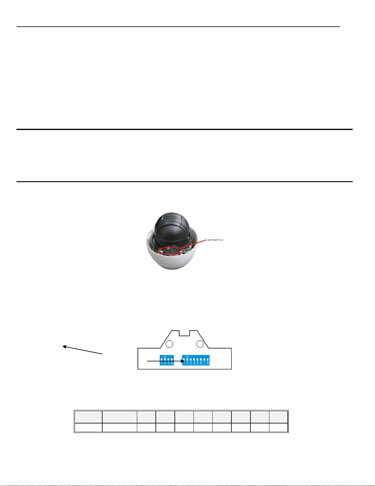
3.1. DIP SWITCH SETTING
Before installing the camera drive, check the DIP switch; configure the receiver address, communication protocol, and baud rate setting.
Pic. 1 shows switch position and default settings. For normal user, setting switches to default position is suggested.
Pic. 1 Switch Position
The camera can be controlled via various communication protocols by setting SW2 switch (3 and 4 bit) and operate at 1200bps, 2400bps,
4800bps and 9600bps baud rate by setting SW2 switch (1and 2 bit). Refer to Table 2: SWITCH SETTING for address, communication
protocol and baud rate settings, do not set the switches to reserved position.
Pic. 2 DIP Switches
Please refer to the below table to set baud rate, communication protocol type and camera address.
8 / 77
Page 13
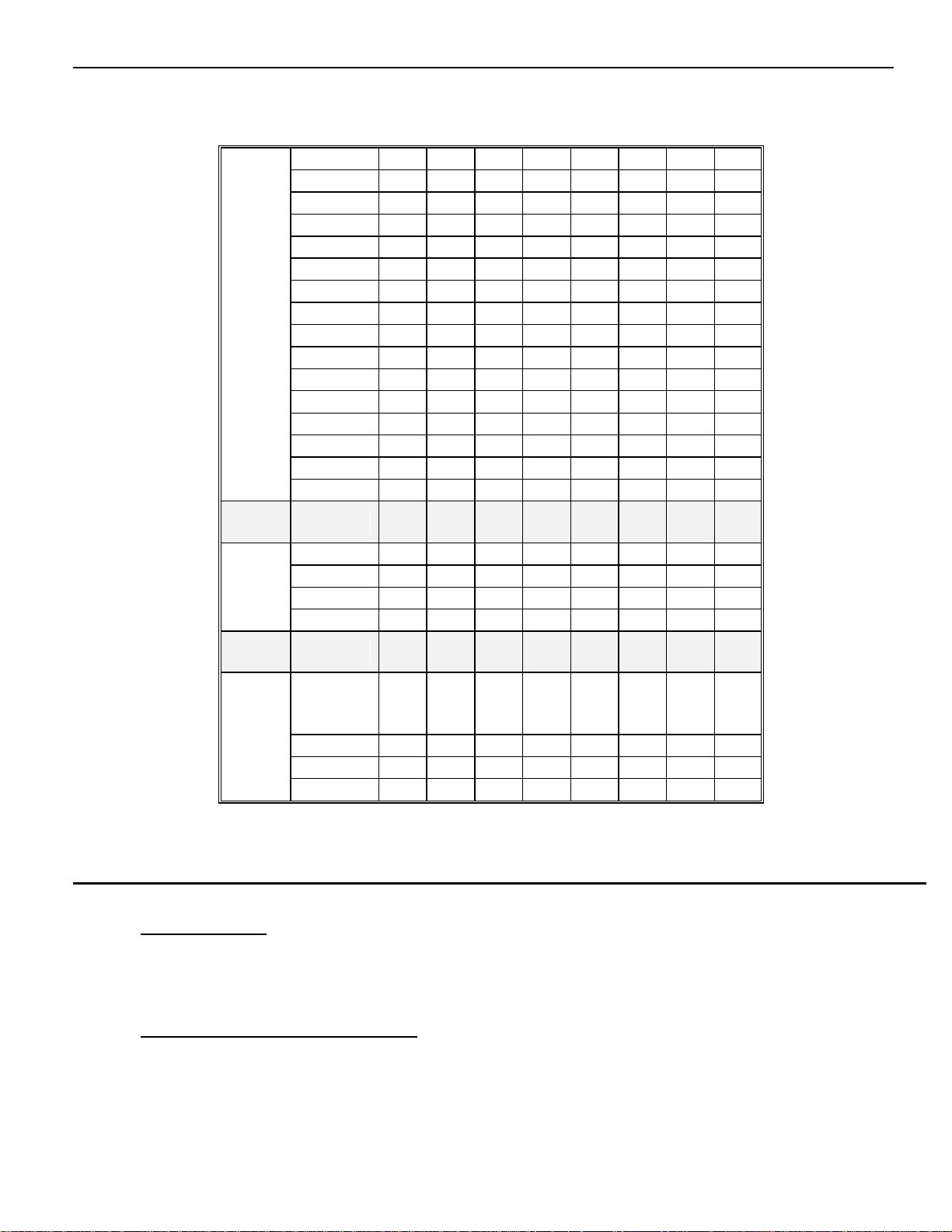
POS
BAUD RATE
1 2
BAUD
RATE
(BPS)
POS
PROTOCOL
3 4
COMM
PTOL
PELCO
(PELCO-P/
OFF
OFF
3.2. INSTALLATION
Step 1. Install lower dome.
Line up the mounting screw holes, and install the three mounting screws. Push the lower dome inside the back box.
Step 2. Install the bracket for wall-mounted dome
Dig four holes on the wall as Pic. 3. Take out the cables from the backward of the bracket. Install the bracket on the wall.
Table 2: SWITCH SETTING
9 / 77
Page 14
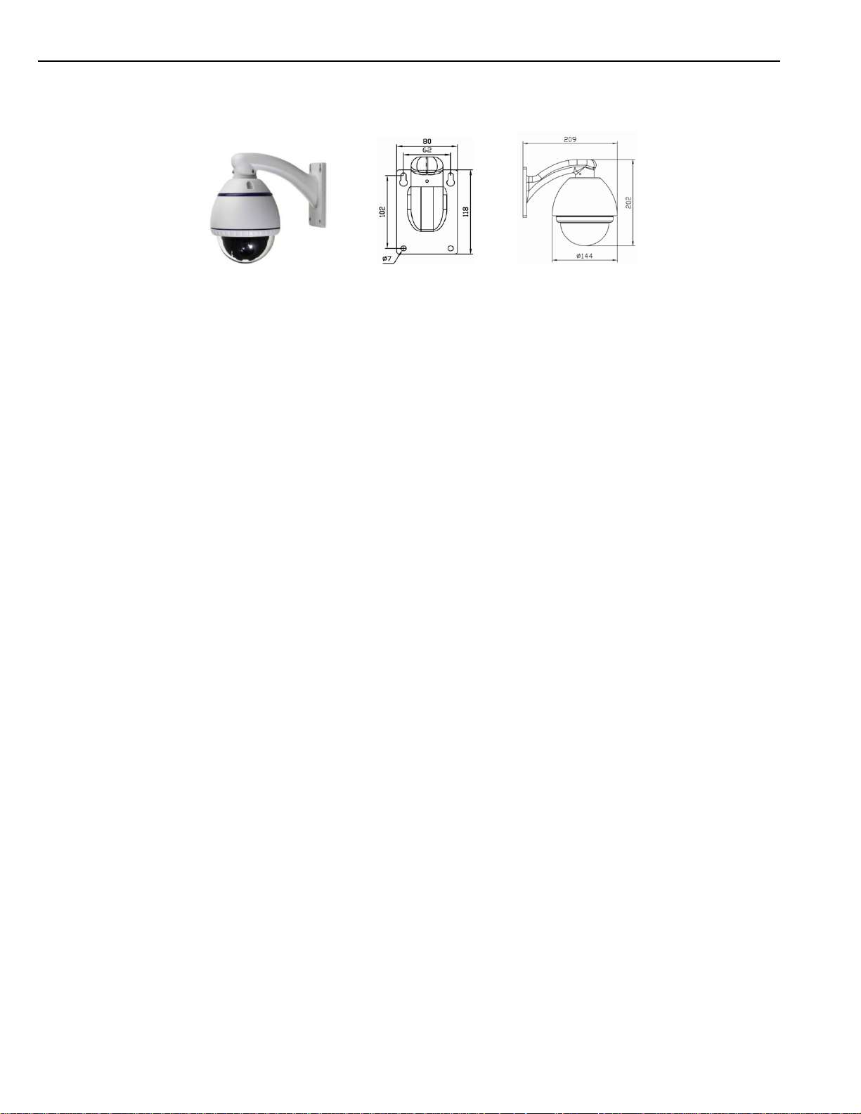
Pic. 3
When installing outdoors, make sure installation is properly sealed to keep moisture out.
Pic. 4
10 / 77
Page 15

SAMSUNG SERI ES CAMERA
4. OPERATION GUIDE
4.1. OPERATION AT POWER UP
The camera employs the default settings the first time it is switched on. Changes to the settings will be permanently stored and will be
made available the next time the camera is switched on. You can return to the default settings by means of the appropriate menu option at
any time.
The camera will work as follows when it is switched on.
The camera will run a calibration procedure and a message showing the following information will appear on the video output OSD
(On Screen Display): software version, address, protocol, baud rate and zoom module brand.
Check that the data are suitable for operation. Otherwise, refer to the section in this document that shows how to install the camera
correctly.
MI NI DOME II
SOFT VERSI ON: 5. 3
ADDRESS: 1
PROTOCOL: PELCO-D/ P
BAUD RATE: 2400
TEMPERATURE 25C
At the end of the calibration step, the camera will switch to stand-by as programmed (PTZ > POWER UP > ACTION). The camera will
continue working this way until any command is received from the keypad. The camera during this phase can be pointed to a fixed point or
pan across the field. Refer to the details described in the POWER UP menu section.
11 / 77
Page 16
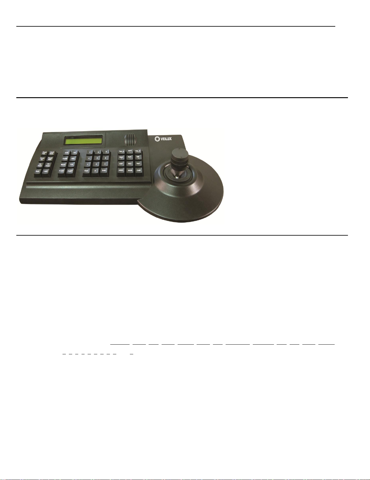
4.2. HOW TO USE OUR CONTROL KEYBOARD
The camera is ready to receive commands from our control keyboard (see figure below) after connecting.
4.2.1. CONTROL KEYPAD COMMAND SYNTAX
Controls can use the joystick, single keys or key combinations.
The key command syntax is shown below.
Key command syntax
The syntax used in this manual for controls using keys consists of various elements (words and three digit numbers). Each command is
always in braces and each element is separated by commas. Each word or decimal digit used in the syntax is identified by a
corresponding key on our control panel. Words can be enclosed in round brackets, square brackets or no brackets. Three digit decimals
are never enclosed in brackets.
The following words only can be used: PRESET, CALL, ESC, OPEN, CLOSE, NEAR, FAR, ZOOM OUT, ZOOM IN, CAM, MON, SCAN, ENTER. The
decimal digits are: 0, 1, 2, 3, 4, 5, 6, 7, 8, and 9.
Some application examples of controls are shown in detail below.
Using the joystick
A command can also be given simply by moving the joystick because this generates actions on the camera or OSD (On Screen Display)
menu.
12 / 77
Page 17

Using a single key
Pressing a single key can cause camera action. For example, the following command will zoom out of the frame. Underling indicates the
key is in use.
ZOOM OUT
Key combinations
Pressing a key combination in rapid sequence extents the command set. For example, the following command (select camera address 1)
is performed by pressing the following keys:
1 + CAM
4.2.2. CONTROL KEYPAD COMMAND TYPES
There are four command types:
Select camera,
Move camera (tilt and pan, zoom, adjust focus and IRIS opening, go to preset positions),
Adjust camera operation mode using menus,
Various quick controls operable from the control panel.
The method for accessing these controls will be shown in details in the following paragraphs.
4.3. SELECT A CAMERA
The camera to be controlled must be selected first. For example, the following command selects camera 1:
1 + CAM
After this operation, the message CAM 1 will appear on the control panel display.
4.4. CAMERA MOTIONS
After selecting a camera, it can be moved either directly using the control panel as described below:
Panning (horizontal) and tilting (vertical).
13 / 77
Page 18

Zooming, focusing and IRIS opening.
Preset positions programming and recalling.
These functions can be directly accessed using a single key or joystick or a simple key combination.
4.4.1. PAN AND TILT FUNCTIONS
The camera may be moved using our keyboard controller. Move the joystick vertically to tilt the camera and horizontally to pan it.
The maximum pan span is from 0º to 360º with continuous rotation. The maximum tilt span is from 0º (camera in vertical position) and 90º.
The panning and tilting speed can be modulated by operating the joystick appropriately.
Note that the maximum speed that can be obtained by operating the joystick is not always equal to that programmed in the working
settings. This in fact depends on the value of the PTZ > MOTION > PROPORTIONAL PAN setting. If the option is ON, the maximum rotation
speed which can be obtained using the joystick is proportional to the magnification used to obtain the best frame.
Panning (horizontal)
Tip the joystick rightwards to turn the camera horizontally clockwise and tip it leftwards to turn it anticlockwise.
If no advanced options are set (e.g. range limits set enabled), the camera can be turned continuously without interruptions.
The pan span may be limited between two angles in PTZ > MOTION > MANUAL LIMIT.
Tilting (vertical)
Tip the joystick upwards to turn the camera vertically upwards and tip it downwards to turn the camera downwards. The camera rotation is
limited upwards by the horizontal plane or downwards by the vertical axis.
Performance will change considerably near the vertical axis according to whether the AUTO FLIP is on or not (default setting is on).
With AUTO FLIP off, the camera will stop in perfectly vertical position and will stop turning when the joystick is tipped downwards.
With AUTO FLIP on, the camera will proceed over the vertical axis when the joystick is tipped downwards. This is because, when the
vertical axis is reached, the camera flips automatically by 180 degrees and resumes the initial trajectory.
The AUTO FLIP function can be used to follow a subject arriving in a certain direction passes under the camera and continues in a straight
14 / 77
Page 19

line. To do this, hold the joystick tipped downwards following the movement of the subject. Observe that in this case the joystick
performance after the camera passes over the vertical axis opposite to the normal axis because tipping the joystick downwards will turn
the camera upwards.
Normal operation of the joystick will be resumed as soon as the downward tip is interrupted (also only for an instant). At this point, to follow
the subject in the same direction, you will need to tip the joystick upwards, as you would normally.
4.4.2. ZOOM FUNCTIONS
The camera frame may be adjusted by using the ZOOM IN and ZOOM OUT commands. Use ZOOM IN to zoom into the detail; use ZOOM
OUT to zoom out.
Zoom can be set as per the zoom specifications of relative modules, combined between optical zoom and digital zoom. Refer to the
specific section for programming the function.
4.4.3. FOCUS FUNCTIONS
The camera focus may be adjusted manually using the NEAR and FAR controls.
As the auto focus function is always on, a manual setting made using NEAR and FAR will be kept only until a pan, tilt or zoom command is
used. In this case, auto focus will adjust focus automatically again.
Refer to the specific section for additional details on focusing and on the various options.
The auto focus function cannot work correctly in the following cases:
The object to be focused on it not in the middle of the image.
There are far and near object in the frame.
Bright light is shining on the subject.
The subject is behind a glass pane covered in drops or dust.
The subject is moving very quickly.
The subject is not well lit.
The subject is too big.
15 / 77
Page 20

Example: programming preset number 32
1) Position the camera in a certain pan, tilt and zoom configuration.
2) Enter the command 32 + HOLD DOWN SHIFT KEY + CALL.
From this moment onwards, simply enter the command 32 + CALL to move the
camera to the preset position.
4.4.4. IRIS OPENING FUNCTIONS
The IRIS opening may be controlled manually using the OPEN and CLOSE commands.
The manual setting made using OPEN and CLOSE will be kept only until a pan, tilt or zoom command is used if the automatic IRIS opening
option is enabled (the default setting is on). In this case, the opening will be controlling automatically again.
Refer to the specific section for additional details on IRIS opening adjustment.
4.4.5. PRESET POSITIONS PROGRAMMING AND RECALLING
The camera can store up to 256 panning, tilting and zooming configurations (called preset positions) which can be recalled at any time.
The manual focusing and IRIS opening settings cannot be stored.
When storing presets, it is important to remember that some are reserved and cannot be either stored or used for positioning
the camera.
Presets from 80 to 99 are reserved for management controls
Presets from 100 to 103, 170 to 173 are reserved for Tracking and Pattern controls
The following examples show how to program the free Presets and recall them.
The saved value will be written over if the setting is reprogrammed.
The Presets are saved in a permanent memory area of the camera where they are maintained also when power is
disconnected. However, restoring default settings will delete all preset values.
Press 83 +HOLD DOWN THE SHIFT KEY + CALL to delete all the saved preset values.
16 / 77
Page 21

10. EXI T
The Presets store the coordinates according to an angular reference system. Therefore, the reference system zero point may
become misaligned with the camera mechanics after prolonged use of the tilting and panning functions. Minor inaccuracies in
preset positions may occur. In this case, calibrate the angular coordinate system using the REBOOT SYSTEM command. This
calibration is automatically run when the camera is switched on.
4.5. FUNCTION PROGRAM MENU
Use the following control panel command to access the function programming menu.
95 + CALL
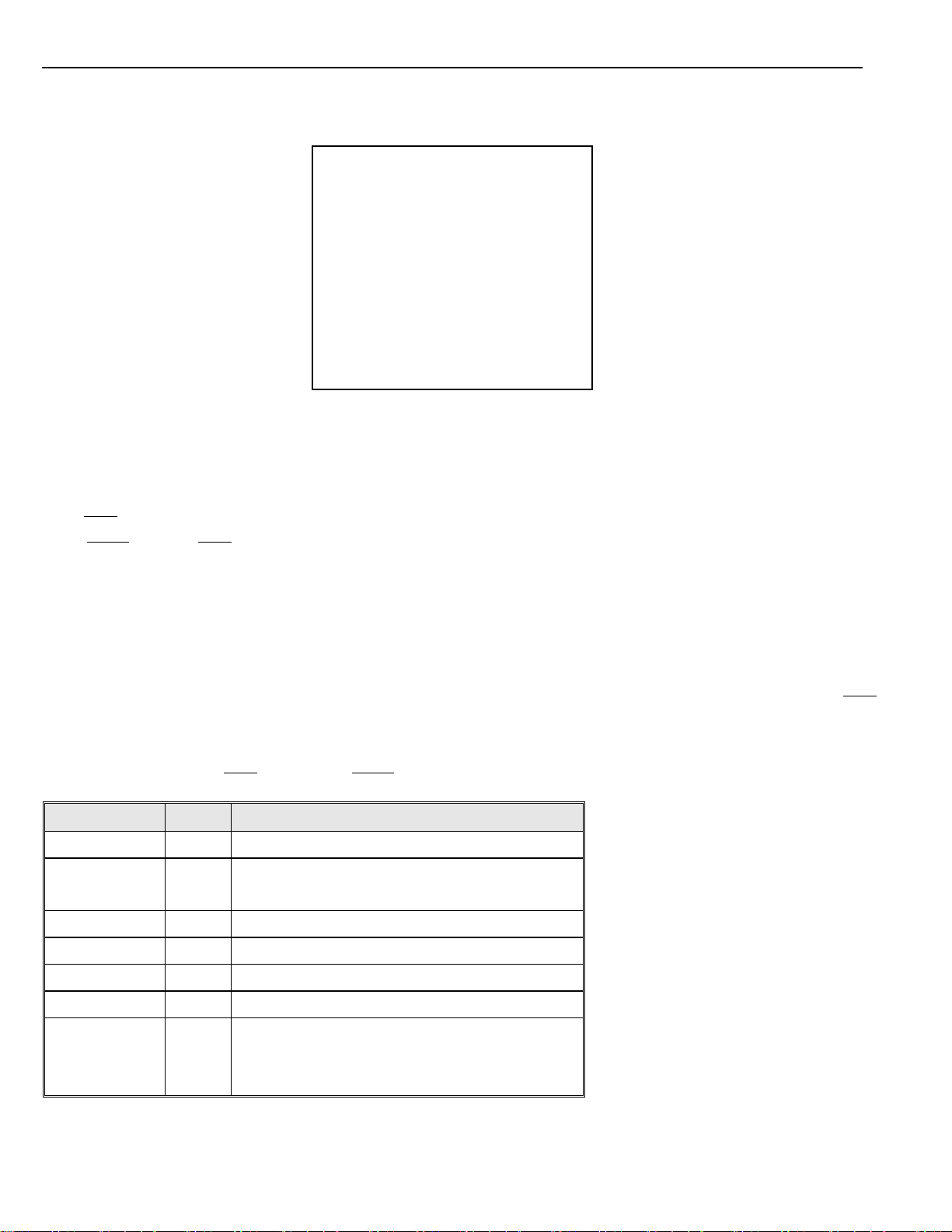
At this point, if no password is required for access, the following first level menu will appear on the screen:
MAI N MENU
- - - - - - - - - - - - - - - - - - - - - - - - - -
--
1. <SYSTEM>
2. <CAMERA>
3. <PTZ>
4. <ALARM>
5. <TRACK>
6. <EVENT>
7. <SET DEFAULT>
8. SYSTEM REBOOT
9. BACK
Screen 1: Main Menu
If a password is required, the following prompt will appear. The password is a numeric combination (max. 4 digits).
17 / 77
Page 22
Option
Value
Explanation
SYSTEM
System setting menu (See Section 4.5.1)
CAMERA
Lens parameters setting menu (See Section Error!
Reference source not found.)
PTZ
PTZ Setting Menu (See Section 4.5.3)
ALARM
Alarm setting menu (See Section 4.5.4)
TRACK
Tracking setup menu (See Section 4.5.5)
EVENT
Event function setting menu (See Section 4.5.6)
SET DEFAULT
This function restarts the device by clearing the
settings performed by the user. The camera is
repositioned.
EXI T
I NPUT PASSWORD
- - - - - - - - - - - - - - - - - - - - - - - - - - - -
-PASSWORD
1 2 3 4 5 6 7 8 9 0
▲
CLEAR
ENTER
Screen 2: Password Protection
Select the password digits by moving the joystick in the horizontal direction. Symbol “▲” indicates the digit to be entered.
Press OPEN to enter the selected digit. The entered numbers will be replaced by an “x” symbol on the screen for privacy.
Select ENTER and press OPEN to access the first level menu after entering all the digits correctly.
THE DEFAULT PASSWORD IS “Blank”.
It is advisable to change the default password to prevent intrusions.
Do not lose or forget the programmed password.
Simply move the joystick vertically to scroll the menu and point the cursor to the menu item to be selected: at this point, select OPEN to
access the selected second level.
Simply press BACK and use OPEN or just press CLOSE to go back to the previous level menu.
`
18 / 77
Page 23
SYSTEM
REBOOT
This function restarts the device without clearly the
settings performed by the user. The camera is
repositioned.
Option
Value
Explanation
SOFT DIP SWITCH
Program protocol, address, baud rate via OSD
menu.
DOME LABEL
Dome label setting submenu
DISPLAY SETUP
Display submenu: program the info to be
displayed on screen.
PASSWORD
Password submenu
BOOTUP SCREEN
Boot up screen submenu
POSITION
MEMORY
ON/OFF
Remember the camera position of last power
off.
8. EXI T
Table 3
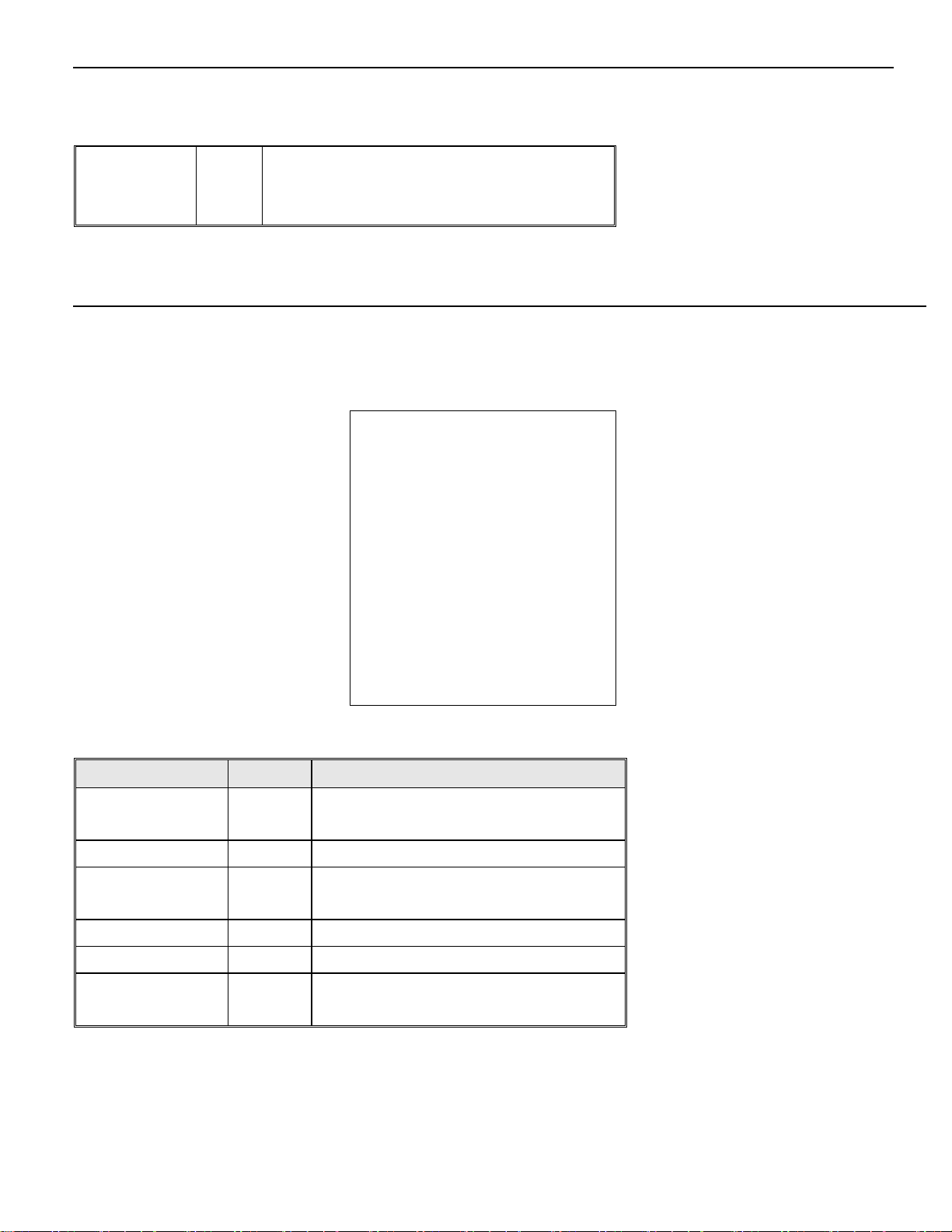
4.5.1. SYSTEM MENU
In the main menu, select SYSTEM to set the parameters such as protocol, baud rate, camera address, dome label, display setup,
password, bootup screen and position memory.
SYSTEM
- - - - - - - - - - - - - - - - - - - - ------
--
1. <SOFT DI P SWI TCH>
2. <DOME LABEL>
3. <DI SPLAY SETUP>
4. <PASSWORD>
5. <BOOTUP SCREEN>
6. POSI TI ON MEMORY: OFF
7. BACK
Screen 3: System
Table 4
19 / 77
Page 24
Option
Value
Explanation
SOFT ADDR
0~255
Set the soft address
SOFT ADDR
ENABLE
ON, OFF
Enable the soft address or not.
SOFT PTOL
DAHUA,
PELCO-D/P
Set the protocol via OSD menu
instead of hard DIP switch
SOFT BAUD
RATE
1200, 2400,
4800,9600
Set the soft baud rate
SOFT
B.RATE/PTOL
ON, OFF
Enable the soft baud rate and protocol
or not.
7. EXI T
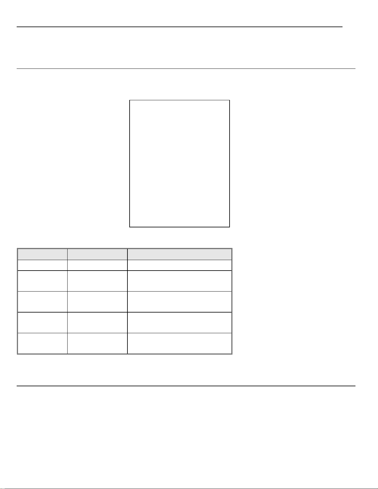
4.5.1.1. SOFT DIP SWITCH
The SOFT DIP SWITCH submenu is used to set protocol, address and baud rate operated by OSD menu.
SOFT DI P SWI TCH
- - - - - - - - - - - - - - - - - - - - - - - - -
--
1. SOFT ADDR:
1
2. SOFT ADDR ENABLE: OFF
3. SOFT PTOL:
PELCO- D/P
4. SOFT BAUD RATE: 2400
5. SOFT B. RATE/ PTOL: OFF
6. BACK
4.5.1.2. DOME LABEL
Screen 4: Protocol Menu
Table 5
20 / 77
Page 25
Option
Value
Explanation
EDIT DOME LABEL
This submenu is used to edit a dome
label (see below).
CLEAR DOME
LABEL
This submenu is to clear the label of the
camera.
4. EXI T
OK CN SP BP
DOME LABEL
- - - - - - - - - - - - - - - - - - - - - - - - - -
--
1. <EDI T DOME LABEL>
2. <CLEAR DOME LABEL>
3. BACK
Screen 5: Dome Label Menu
Table 6
EDIT DOME LABEL submenu
The operations needed to associate a label to a camera are:
1) Use the joystick to point the cursor to the "EDIT DOME LABEL” option.
2) Press OPEN. The following menu will appear on the display:
DOME
DOME LABEL
0123456789 YZ YZ
ABCDEFGHI JKLMNOPQRSTUVWX
abcdef ghi j kl mnopqr st uvwx
Screen 6: Dome Label
3) Point the cursor to the first character to be used and press OPEN. Point the cursor to “BP” (BACKSPACE) to delete it.
4) After writing the text, point the cursor to OK and press OPEN to save and go back to the main screen.
5) OK means CONFIRMATION, CN means CANCEL, SP means character SPACE, BP means character BACKSPACE
21 / 77
Page 26

Option
Value
Explanation
CLOCK
Set the date and time.
ORIENTATION
The orientation setting submenu.
DOME LABEL
ON/OFF
Show or hide the label
ZOOM
ON/OFF
Show or hide zoom labels.
AZIMUTH/ELEVATION
ON/OFF
Show or hide camera pan/tilt labels. The
coordinates refer to the monitor center.
PRESET LABEL
ON/OFF
Show or hide preset labels.
ZONE LABEL
ON/OFF
Show or hide zone label.
EVENT LABEL
ON/OFF
Show or hide event label.
LABEL POSITION
Label positioning submenu
11. EXI T
4.5.1.3. DISPLAY SETUP
The DISPLAY SETUP submenu is used to enable the labels to be displayed for the various camera functions.
DI SPLAY SETUP
- - - - - - - - - - - - - - - - - - - - - - - - -
--
1. <CLOCK>
2. <ORI ENTATI ON>
3. DOME LABEL:
ON
4. ZOOM:
ON
5. AZI MUTH/ ELEVATI ON: ON
6. PRESET LABEL: ON
7. ZONE LABEL:
ON
8. EVENT LABEL: ON
9. <LABEL POSI TI ON>
10. BACK
Screen 7: Display Setup
22 / 77
Page 27

Option
Value
Explanation
CLOCK
DISPLAY
ON/OFF
Show or hide the date and time
DATE
Set the date. The format is YYYY/MM/DD.
TIME
Set the time. The format is 24 hour
(HH:MM:SS).
5. EXI T
4. EXI T
Clock Submenu
The CLOCK submenu is used to set the date and the time.
- - - - - - - - - - - - - - - - - - - - - - - - - -
-
1. CLOCK DI SPLAY: ON
2. DATE: 2010/ 11/ 30
3. TI ME: 13: 12: 09
4. BACK
Table 7
CLOCK
Screen 8: Clock
Table 8
Orientation Submenu
The ORIENTATION submenu is used to set the direction. The camera can tell which direction the camera is facing.
ORI ENTATI ON
- - - - - - - - - - - - - - - - - - - - - - - - - -
-
1. DI SPLAY: ON
2. PRI ME DI RECTI ON: N
3. BACK
23 / 77
Page 28

Screen 9: Orientation
Option
Value
Explanation
DISPLAY
ON/OFF
Show or hide the orientation
PRIME
DERECTION
N/S/E/W/NW/N
E/SW/SE
Set the prime direction
TI ME DATE
Label Position Submenu
The labels may be positioned where required on the screen.
ZONE CAMERA PRESET
ORI ENT
EVENT
SAVE
RESET
AZI MUTH ZOOM
Table 9
Screen 10: Label Position
To establish a position:
1) Point the cursor to the label to be moved by moving the joystick vertically.
2) Press OPEN.
3) Symbol “■” will appear.
4) Position the entire label in the chosen position using the joystick.
5) Press OPEN.
6) Repeat this operation for each label.
7) Point the cursor “►” to SAVE and press OPEN.
4.5.1.4. PASSWORD
24 / 77
Page 29

Option
Value
Explanation
ENABLE
PASSWORD
ON/OFF
This enables or disables the password.
EDIT PASSWORD
This is the password entry procedure.
4. EXI T
BACK
PASSWORD
- - - - - - - - - - - - - - - - - - - - - - - - - - -- - -
--
1. ENABLE PASSWORD: OFF
2. <EDI T PASSWORD>
3. BACK
Screen 11: Password
Table 10
The password is a numeric combination (max. 10 digits).
THE DEFAULT PASSWORD IS “1111”.
It is advisable to change the default password to prevent intrusions.
Do not lose or forget the programmed password.
I NPUT OLD PASSWORD
PASSWORD
1234567890
CLEAR
ENTER
1) Select the password digits by moving the joystick horizontally. Symbol “▲” indicates the digit to be entered.
2) Press OPEN to enter the selected digit.
3) The entered numbers will be replaced by a “*” symbol on the screen for privacy.
4) Enter all the digits correctly and select ENTER to confirm.
5) During the password change procedure you will be asked to enter the old password. Enter the new password and enter it again for
Screen 12: Edit Password
25 / 77
Page 30

SAMSUNG SERI ES CAMERA
confirmation.
4.5.1.5. BOOTUP SCREEN
In the SYSTEM menu, select BOOTUP SCREEN to display information concerning software version, address, protocol, baud rate and zoom
module brand. The information in this menu cannot be edited.
MI NI DOME Ⅱ
SOFT VERSI ON: 5. 3
ADDRESS: 1
PROTOCOL: PELCO-D/ P
BAUD RATE: 2400
TEMPERATURE 25C
Screen 13: Boot up Screen
26 / 77
Page 31

4.5.2. MENU AND FUNCTIONS
Use the button on the back panel of the camera to bring up the menu screen for controlling functions and operations of the camera.
• Main Menu Screen like the following will appear when Menu button is pressed for two second
2. Menu and Functions
Same to the Rear side of X27
Module
1. Key Operations
• Menu :: Low Middle [LIGHT] Î [MENU On] , [MENU Set]
• Accessing Sub Menu :: Center Side [I] , [O] Î [Up] , [Down]
• Select a Value :: Low Side [B] , [NW] Î [Left] , [Right]
Use Five buttons above to browse the menu options.
2.Entering Menu Screen
• When camera is turned on, press and hold the middle
[MENU On] button for 2 seconds.
• [MENU] button is used for [MENU On] and [MENU Set]
3. Main Menu
< Figure 1. Main Menu>
3. Browsing through Menu Options
27 / 77
Page 32

• The curser will be initially at [FOCUS].
• [ ] gets displayed in front of the selected menu options.
• Use [UP] and [DOWN] button to move the cursor.
• When the curser is at the desired position, press the [menu Set] button to go into the selected sub menu screen.
4. Exiting the Menu
• Bring the curser to [SAVE & EXIT] and press the Menu button. Then the Menu Screen will disappear
5. Focus Menu
• In the Main Menu, go into the [FOCUS ] sub menu screen by bringing the curser to [FOCUS ] and pressing [menu Set] button.
< Figure 2. Focus Menu>
5-1. Focus Mode
• Changes the Focus Mode.
• Bring the curser to [FOCUS MODE ], and change the option using [LEFT] or [RIGHT] button.
• The following options are available.
¾ AUTO : The camera will focus automatically. <Recommended>
¾ MANUAL : The focus will be focused by the user manually.
¾ PUSH : The Focus gets automatically set by pressing the Menu button shortly.
5-2. Focus Distance
• Changes the focal distance of an object.
• Bring the curser to FOCUS DIST ], and change the value using [LEFT] or [RIGHT] button.
• The following options are available.
¾ 10cm Î 50cm Î 1m Î 1.5m Î 2m Î 3m Î 5m
28 / 77
Page 33

5-3. Zoom Start
• Changes the minimum zoom magnification rate.
• Bring the curser to [ZOOM START], and change the value using [LEFT] or [RIGHT] button.
• The following options are available.(x1~x12)
¾ Any ratio between X1 and x35 can be selected.
5-4. Zoom End
• Changes the maximum zoom magnification rate.
• Bring the curser to [ZOOM END], and change the value using [LEFT] or [RIGHT] button.
• The following options are available.(X2 ~ X144)
¾ Please note that x1 cannot be selected for Maximum zoom.
5-5. Zoom Tracking Mode
• Changes the Zoom Tracking.
• Bring the curser to [ZOOM TRK MODE], and change the value using [LEFT] or [RIGHT] button.
• The following options are available.
¾ AUTO: The focus gets adjusted automatically when zoom Lens is moved.
¾ OFF: The focus stays at its setting when zoom Lens is moved.
¾ MANUAL: The focus gets adjusted to the position specified by the user when zoom Lens is moved.
5-6. Zoom Speed
• Changes the Speed of the Zoom lens movement.
• Bring the curser to [ZOOM SPEED ], and change the option using [LEFT] or [RIGHT] button.
• The following options are available.
¾ NORMAL
¾ QUICK
¾ SLOW
5-5. Lens Initial
• Initializes to the default Focus and Zoom values.
• Bring the curser to [LENS INITIAL], and change the option using [LEFT] or [RIGHT] button.
• The following options are available.
¾ AUTOS
¾ OFF
¾ ONE PUSH
• Select [ONE PUSH] and press [menu Set] button to manually initialize the lens.
29 / 77
Page 34

• Select [AUTO] and press [menu Set] to set an automatic Lens initialization period. 1day ~ 7day
5-6. INITIAL SET (Same for all sub menus)
• All values in Focus Menu will be set to default.
• Bring the curser to [INITIAL SET] , and press the [menu Set] button to execute reset.
All configurations in FOCUS MODE~ LENS INITIAL option will be set to default value
5-7. PREVIOUS (Same for all sub menus)
• Brings the screen to previous screen.
• Move the cursor to [PREVIOUS], and press the [menu Set] button to go to the upper menu screen.
• Selecting this at FOCUS Menu will bring the root [Main Menu] Screen.
6. Exposure Menu
• In the Main Menu, go into the [Exposure] sub menu screen by bringing the curser to the [Exposure] and pressing [menu Set] button.
< Figure 3. Exposure Menu>
6-1. Brightness
• Changes the Brightness level.
• Move the cursor to [BRIGHTNESS], and change the value using [LEFT] or [RIGHT] button.
¾ It can be set in between 0 and 100, where 50 is the normal brightness.
6-2. Iris
• Changes the Iris mode.
• Move the cursor to [Iris], and change the option using [LEFT] or [RIGHT] button.
¾ AUTOS
30 / 77
Page 35

¾ MANUAL ※ Manual controls is disabled when using WDR in Backlight option.
It can be set between 0 and 100, where 60 is considered to be normal.
6-3. Shutter
• Changes the electrical shutter operation.
• Move the cursor to [SHUTTER], and change the option using [LEFT] or [RIGHT] button.
• When the setting is changed to [MANUAL], press [menu Set] button to go into the manual shutter speed change menu screen.
¾ AUTO : The camera automatically changes the shutter Speed.
¾ A- FLK : The shutter speed sets to 1/100(NTSC) or 1/120(PAL).
¾ MANUAL : The shutter speed gets set by the user manually.
¾ The value can be selected between X512 and X2(LOW) , 1/60 and 1/90000(HIGH) seconds.
Manual control is disabled when using WDR in the BackLight option
※
6-4. AGC
• Changes the maximum value for the Automatic Gain Control.
• Move the cursor to [AGC], and change the value using [LEFT] or [RIGHT] button.
¾ LOW Î 12 dB
¾ MIDDLE
Î 24 dB
¾ HIGH Î 32 dB
¾ MANUAL Î 0~32 dB ※ Manual control is disabled when 3D-DNR or D/N mode is set to [ON]
6-5. Sense-Up
• Changes the number of images to be accumulated at low light
• Move the cursor to [SENS-UP], and change the value using [LEFT] or [RIGHT] button.
¾ OFF
¾ AUTO X2 ~ X128
6-6. INITIAL SET (Same for all sub menus)
6-7. PREVIOUS (Same for all sub menus)
7. White Balance Menu
• In the Main Menu, go into the [WHITE BALANCE] menu screen by bringing the cursor to the [WHITE BALANCE]
and pressing [menu Set] button.
31 / 77
Page 36

<Figure 4. White Balance Menu>
7-1. W/B Mode
• Selects the White Balance Mode
• Move the cursor to [W/B MODE], and change the value using [LEFT] or [RIGHT] button.
¾ AWB: 2,200 ~ 7,000 K
¾ ATW: 2,000 ~ 18,00 K
¾ PUSH: Execute the ATW operation when [MENU SET] button is pressed
¾ IN DOOR: Sets the standard color temperature to an indoor level. (3200 K)
¾ OUTDOOR: Sets the standard color temperature to an outdoor level. (5100 K)
¾ MANUAL: The user sets the W/B value for RED and BLUE color (refer to 7-5)
7-2. Anti – Color Rolling
• Eliminates Color-rolling effect when using High – shutter speed.
• Move the cursor to [ANTI ROLLING], and change the option using [LEFT] or [RIGHT] button.
¾ ON : Turns the feature on.
¾ OFF : Turns the feature off.
7-3. INITIAL SET (Same for all Sub Menus)
7-4. PREVIOUS (Same for all Sub Menus)
32 / 77
Page 37

<Figure 5. Manual White Balance Menu>
7-5
a. W/B RED (Adjusting the Red gain level)
• Changes the Red Gain Level.
• Move the cursor to [W/B RED], and change the value using [LEFT] or [RIGHT] button.
¾ Can be changed between -100 and 100, where 0 is the normal value.
b. W/B BLUE (Adjusting the Blue gain Level)
• Changes the Blue Gain Level.
• Move the cursor to [W/B Blue], and change the value using [LEFT] or [RIGHT] button.
¾ Can be changed between -100 and 100, where 0 is the normal value.
c. INITIAL SET (Same for all sub menus)
d. PREVIOUS (Same for all sub menus)
8. Day/ Night Menu
• In the Main Menu, go into the [DAY / NIGHT] sub menu screen
by bringing the cursor to the [DAY / NIGHT] and pressing [menu Set] button.
< Figure 6. Day/ Night Menu >
8-1. Day/ Night mode change
• Configures the operation of IR-CUT filter according to Day /Night light level.
• Move the cursor to [D/N MODE], and change the option using [LEFT] or [RIGHT] button.
¾ AUTO: Camera will automatically determine the light level
¾ DAY: Always in Day mode. (IR-CUT filter engaged all the time)
33 / 77
Page 38

¾ NIGHT: Always in Night mode. (IR-CUT filter disengaged all the time)
¾ EXT: Mode changes according to an external signal.
¾ CDS: Mode changes according to the CDS SENSOR.8-2. Day/Night Level
8-2. Day/Night Level
• Changes the light level for Day/Night switching
• Move the cursor to [D/N Level], and change the value using [LEFT] or [RIGHT] button.
¾ Can be changed in between 0 and 10, where 5 is the normal value. (Switching light level is 0<5<10)
8-3. Day/Night delay
• Sets the delay time for Day/Night switching
• Move the cursor to [D/N Delay], and change the value using [LEFT] or [RIGHT] button.
¾ Can be set in between 5 ~ 60 seconds.
8-4. INITIAL SET (Same for all sub menus)
8-5. PREVIOUS (Same for all sub menus)
9. Backlight Menu
• In the Main Menu, go into the [BACKLIGHT] sub menu screen by bringing the cursor to the [BACKLIGHT] and pressing [menu Set] button.
34 / 77
Page 39

9-1. Backlight mode
• Changes Backlight Mode.
• Move the cursor to [BACKLIGHT], and change the option using [LEFT] or [RIGHT] button.
¾ OFF: No Back Light Compensation
¾ WDR: Wide Dynamic Range
¾ BLC: Back Light Compensation
¾ ECL: Eclipse
• Press [menu Set] button when desired mode option gets displayed to go into the sub menu screen for further configuration.
10. WDR Menu
• In the [BACKLIGHT] option, press the [Menu Set] Button when
WDR is displayed to go into the [WDR] sub menu screen
< Figure 8. WDR Menu >
10-1. WDR
• Selects which WDR Mode to use.
• Move the cursor to [WDR LEVEL], and press [LEFT] or [RIGHT] button to change the option.
¾ W-FRONT: Compensation for Dim Light Area front 00 %, Back 00 %
¾ W-CENTER: Compensation for Normal Light Area front 00 %, Back 00 %
¾ W-REAR: Compensation for Strong Light Area front 00 %, Back 00 %
¾ W-USER: The user configures the desired value
• Press the [menu Set] button when W-USER is displayed to go into the W-USER menu screen.
35 / 77
Page 40

¾ LONG: selects in between 0 and 60.
¾ SHORT: selects in between 0 and 60.
10-2. PREVIOUS (Same for all sub menus)
11. Backlight Menu
• In the [BACKLIGHT] option, press the [Menu Set] Button when [BLC] is displayed to go into the [BLC] sub menu screen
< Figure 9. Backlight menu >
11-1. Backlight
• Selects which BLC Mode to use.
• Move the cursor to [BLC LEVEL], and press [LEFT] or [RIGHT] button to change the option
¾ MIDDLE: Normal Back light compensation
¾ HIGH: Strong Back light compensation.
¾ LOW : Dim Back light compensation.
11-2. PREVIOUS (Same for all sub menus)
12. ECL Menu
• In the [BACKLIGHT] option, press the [Menu Set] Button when ECL is displayed to go into the [ECL] menu screen
36 / 77
Page 41

< Figure 10. ECL Menu >
12-1. ECL Area
• Configures Eclipse Area.
• Move the cursor to [AREA SETTING], and press [menu Set] button to go into the sub menu.
¾ The total area consists of 16 cells (4 by 4)
¾ Use [LEFT] or [RIGHT] buttons to move to the desired area.
¾ Use [UP] or [DOWN] buttons to turn each Eclipse area ON or OFF
¾ Press [menu Set] button to go back to the upper menu screen
• Select [ALL AREA SET] option using [LEFT] or [RIGHT] button.
¾ Selects all 16 areas
12-2. Mask Color
• Selects the Eclipse Mask Color.
• Move the cursor to [MASK COLOR], and use [LEFT] or [RIGHT] button to change the color.
¾ BLACK, GRAY, and Dark GRAY can be selected.
12-3. ECL activate level
• Sets the light level for Eclipse activation
• Move the cursor to [ECL LEVEL], and press [LEFT] or [RIGHT] button to change the value.
¾ Can be selected in between 0 and 100, where 50 is the normal level.
12-4. INITIAL SET (Same for all sub menus)
12-5. PREVIOUS (Same for all sub menus)
13. 3D DNR Menu
• In the main menu, move the cursor to [3D-DNR], and press the [LEFT] or [RIGHT] button to show different options. Press [menu Set] button when [On] is displayed to go into the
3D DNR Menu Screen.
37 / 77
Page 42

¾
OF
: 3D DNR disabled.
¾
ON
: 3D DNR enabled.
< Figure 11. 3D-DNR Option in the Main Menu >
13-1. 3D DNR mode
• Turns 3D digital Noise Reduction option on or off.
• Move the cursor to [3D-DNR], and press [LEFT] or [RIGHT] button to change the option.
< Figure 12. 3D – DNR Menu >
13-2. 3D-DNR level
• Configures Noise Reduction level.
• Move the cursor to [3D - DNR], and press [LEFT] or [RIGHT] button to change the value.
¾ Can be selected in between 0 and 63, where 32 is the normal value.
13-3. Global Motion
• Eliminates ‘the ghost effect’ when using 3D-DNR feature.
• Move the cursor to [GLOBAL MOTION], and press[LEFT] or [RIGHT] button to change the option.
¾ ON : Enables Global Motion Compensation.
38 / 77
Page 43

¾
OFF
: Displays the Real time image
¾
ON
: Freezes the image Display.
¾ OFF : Disables Global Motion Compensation.
13-4. INITIAL SET (Same for all sub menus)
13-5. PREVIOUS (Same for all sub menus)
14. Image Adjust Menu
• In the Main Menu, select [IMAGE ADJUST] using [menu Set] button to go into [IMAGE ADJUST] menu screen.
< Figure 13. Image Adjust Menu>
14-1. D-Effect
• Selects which Digital Effect Option to use.
• Move the cursor to [D - EFFECT], and press [LEFT] or [RIGHT] button to change the option.
¾ OFF : No digital Effect.
¾ V- FLIP : Flips the image vertically.
¾ MIRROR : Flips the image horizontally.
¾ ROTATE : Flips the image both horizontally and vertically
14-2. Image Freeze
• Freezes the image.
• Move the cursor to [IMAGE FREEZE] , and press [LEFT] or [RIGHT] button to change the option.
14-3. Color / Black and White
39 / 77
Page 44

• Selects the image output to be color or B/W.
• Move the cursor to [COLOR], and press [LEFT] or [RIGHT] button to change the selection.
¾ ON: Color Image Output
¾ OFF: B/W Image Output
14-4. Sharpness
• Changes the Image’s Sharpness level.
• Move the cursor to [SHARPNESS], and press [LEFT] or [RIGHT] button to change the value.
¾ Can be changed in between 0 and 100, where 60 is the normal value.
¾ OFF: Displays Black and White.
14-5. Gamma
• Adjusts the Image’s Gamma Level.
• Move the cursor to [GAMMA], and press [LEFT] or [RIGHT] button to change the option.
• Select [USER] option by pressing [menu Set] button to go into the [USER] menu screen.
¾ CRT : pre-configured gamma level for a CRT monitor (0.45)
¾ LCD : pre-configured gamma level for an LCD monitor (1.00)
¾ USER: The user can select the level. Select in between 0.45~ 1.
14-6. INITIAL SET (same for all sub menus)
14-7. PREVIOUS (same for all sub menus)
15. Special Menu
• In the main menu, move the cursor to [SPECIAL] and press [menu Set] button to go into [SPECIAL] menu Screen.
40 / 77
Page 45

< Figure 14. Special Menu >
15-5. Stabilizer
• Stabilizes the image on slight fluctuations.
• Move the cursor to [STABILIZER] and press [LEFT] or [RIGHT] button to turn on or off
15-6. L/L Sync
• Sets the source for the line lock.
• Move the cursor to [L/L SYNC] and press [LEFT] or [RIGHT] button to change the value.
¾ INT, L/L(0~359)
15-7. Factory Initial
• Initializes the camera to factory default mode.
• Move the cursor to [FACTORY INITIAL] and press [Menu Set] button for reset.
15-8. Reboot
• Move the cursor to [REBOOT] and press [Menu Set] button to reboot the camera.
15-1. Comm. Adjust
• In [Special] Menu, select [COMM ADJUST] by pressing [menu Set] button to go into [COMM ADJUST] menu screen.
41 / 77
Page 46

< Figure 15. Comm. Adjust menu>
15-1-1. Protocol
• Selects communication protocol to use.
• Move the cursor to [PROTOCOL] and press [LEFT] or [RIGHT] button to change the option.
¾ Five protocols are selectable - CNB-ASCII , CNB-HEX , PELCO-D , PELCO-P
15-1-2. Camera ID
• Configures the Camera’s ID.
• Move the cursor to [CAMERA ID] and press [LEFT] or [RIGHT] button to change the ID.
¾ Can be selected in between 0 and 255 where 0 is the initial value.
15-1-3. Save/ Reboot
• The change in the configuration setting will apply after it was saved/ rebooted.
15-1-4. PREVIOUS (same for all sub menus)
¾ Exit without saving 32
15-2. Motion Detection Menu
• In the Special Menu Screen, Select [MOTION DET] by pressing [menu Set] button to go into the [MOTION DET] menu screen.
42 / 77
Page 47

< Figure 15. Motion Det. Menu>
15-2-1. Detection Zone
• Up to 4 zones can be configured.
• Move the cursor to [ZONE NUMBER] and press [LEFT] or [RIGHT] button to select the desired zone.
¾ Configuration for each zone needs to be done separately when you select a different zone.
15-2-2. Zone State
• Turns on or off the selected movement detection zone.
• Move the cursor to [ZONE STATE] and press [LEFT] or [RIGHT] button to change the selection.
¾ Can be configured to be ON or OFF.
15-2-3. Size of the Detection Zone
• Configures the size of the selected detection zone
• Move the cursor to [WIDTH] or [HEIGHT] and press [LEFT] or [RIGHT] button to change the value.
¾ WIDTH: Changes the width of the detection zone.
¾ HEIGHT: Changes the height of the detection zone.
15-2-4. Location of the Detection Zone
• Configures the location of the selected detection zone
• Move the cursor to [MOVE X] or [MOVE Y] and press [LEFT] or [RIGHT] button to change the value.
¾ Move X: Moves the detection zone horizontally.
¾ Move Y: Moves the detection zone vertically.
15-2-5. Motion Zoom
• Can zoom in the image when a motion is detected on the selected detection zone.
• Move the cursor to [MOTION ZOOM] and press [LEFT] or [RIGHT] button to change the setting.
• Change the option to [ON] and press [menu Set] button to go into the sub menu screen.
¾ [TARGET ZOOM] : sets the zoom magnification upon motion detection.
¾ The maximum zoom is limited to the optical zoom
¾ [D – WELL] : dwell time to stay on that zoom magnification
43 / 77
Page 48

¾ Can be selected in between 10 and 60 seconds.
15-2-6. Sensitivity
• Sensitivity to detect motion on the selected detection zone.
• Move the cursor to [SENSTIVITY] and press [LEFT] or [RIGHT] button to change the setting.
¾ Can be selected in between 0 and 100, where 50 is the normal value.
15-2-7. MD Alarm Out
• Sets the Alarm Output upon when motion is detected.
• Move the cursor to [MD ALARM OUT] and press [LEFT] or [RIGHT] button to change the setting.
¾ ON : [MD] gets displayed on the screen, and the Alarm Output gets activated.
¾ OFF : Motion Detection does not get alerted.
15-2-8. INITIAL SET (Same for all Sub menus)
15-2-9. PREVIOUS (Same for all Sub menus)
15-4. Privacy Mask Menu
• In the Special Menu screen, select [PRIVACY MASK] and press
[menu Set] button to go in to the [PRIVACY MASK] menu screen.
< Figure 16. Privacy Mask Menu>
15-4-1. Masking Zone
• Up to 8 zones can be configured.
• Move the cursor to [MASK NUMBER] and press [LEFT] or [RIGHT] button to change the value.
¾ Configuration for each zone needs to be done separately when you select a different zone.
44 / 77
Page 49

15-4-2. Mask State
• Turns on or off the selected masking zone.
• Move the cursor to [MASK STATE] and press [LEFT] or [RIGHT] button to change the State.
¾ Select in between ON and OFF
15-4-3. Mask Color
• Selects the color for the masking.
• Move the cursor to [MASK COLOR] and press [LEFT] or [RIGHT] button to change the State.
>Can be selected in between GRAY, YELLOW, GREEN, RED, BLUE, BLACK, and WHITE.
15-4-4. Size of the Masking Zone
• Configures the size of the selected Masking zone.
• Move the cursor to [WIDTH] or [HEIGHT] and press [LEFT] or [RIGHT] button to change the value.
¾ WIDTH: Changes the width of the Masking zone.
¾ HEIGHT: Changes the height of the Masking zone.
15-4-5. Location of the Masking Zone
• Configures the location of the selected Masking zone.
• Move the cursor to [MOVE X] or [MOVE Y] and press [LEFT] or [RIGHT] button to change the value.
¾ Move X: Moves the Masking zone horizontally.
¾ Move Y: Moves the Masking zone vertically.
15-4-6. Reset Mask
• The configured size and location on the selected masking zones can be set back to the initial state.
• Move the cursor to [RESET MASK] and press [menu Set] button for reset.
15-4-7. INITIAL SET (same for all sub menus)
15-4-8. PREVIOUS (same for all sub menus)
16. OSD Setup Menu
• In the main menu screen, move the cursor to [OSD SETUP] and press [menu Set] button to go into the [OSD SETUP] screen.
45 / 77
Page 50

< Figure 17. OSD Setup Menu>
16-1. Zone Label
• Configures the name of the zone and turns On or Off its display.
• Move the cursor to [ZONE LABEL] and press [LEFT] or [RIGHT] button to change the state.
¾ Press [menu Set] button when selecting [On] to go into the sub menu screen
16-2. Location of Camera ID
• Use this to label certain Cam ID (configured at Comm.
Adjust menu) to a specific name or change the location of the label display.
• Move the cursor to [CAMERA ID] and press [LEFT] or [RIGHT] button to change the state.
¾ Select [On] and press [menu Set] button to go into the sub menu screen.
46 / 77
Page 51

< Figure 18. Zone Label Screen >
16-1-1. Zone Label
• Sets the name of the zone and display location in the screen
¾ Letter selection section on the top, and preview section at the bottom. Blinking curser indicates which section you are at.
¾ You can browse through the letter selection section on the top and the menu section in the middle using [LEFT] , [RIGHT] , [UP], or [DOWN] button.
¾ Press [menu Set] button to select the highlighted letter, and it will get displayed on the preview section at the bottom
¾ [Í][Î] : Moves the curser. Can also be used as a space bar
¾ [CLR]: erases all letters written
¾ [POS]: Sets the position of the name display.
¾ [END]: Save/ Exit to the upper menu screen.
16-2-1. Camera ID label
• Sets the position of the Camera ID.
¾ Go into the sub menu screen and change the position using [LEFT] or [RIGHT] button.
16-3. Zoom magnification Display
• Sets the zoom magnification display on or off and also configures the display position
• Move the cursor to [ZOOM IMAG] and press [LEFT] or [RIGHT] button to change the option.
16-4. Motion Zoom Display
• Sets the display of Motion Zoom. When turned on, it displays [MD] upon detecting motions.
• Move the cursor to [MOTION DET] and press [LEFT] or [RIGHT] button to change the option.
16-5- FUNCTION Display.
47 / 77
Page 52

Option
Value
Explanation
MOTION
Camera motion parameter programming
submenu
PRESETS
Preset parameter submenu
SCAN
Pattern and zone parameter submenu
POWER UP
Power up parameter submenu
CRUISE
Cruise parameter programming submenu
9. EXI T
Sets the display of various functions such as BLC, D-EFFECT, DAY&NIGHT, and W/B mode on the screen.
16-6. Language
• This version can only display English.
• In case another language is added, move the cursor to [MOTION DET] and press [LEFT] or [RIGHT] button to change the setting.
16-7. INITIAL SET (same for all sub menus)
16-8. PREVIOUS (same for all sub menus)
4.5.3. PTZ MENU
In the main menu, select <PTZ> and the corresponding submenus to access the menu.
PTZ
- - - - - - - - - - - - - - - - - - - - ---
--
1. <MOTI ON>
2. <PRESETS>
3. <SCAN>
4. <POWER UP>
5. <CRUI SE>
6. <CLEAR SET>
7. PRESETS NUMBER: 256
8. BACK
Screen 14: PTZ Menu
48 / 77
Page 53

CLEAR SET
Clear settings submenu
PRESET
NUMBER
256/64/40
Maximum number of Presets. Always enter 256
Option
Value
Explanation
AUTO FLIP
ON/OFF
When this option is on, the
movements of a subject moving
underneath the camera can be
followed by moving the joystick
vertically only. This is possible
because after reaching vertical
position, the camera will
automatically pan by 180 degrees to
be repositioned and resume the tilt
stroke.
9. EXI T
Table 11
4.5.3.1. MOTION
The first level of this menu contains the following options grouped as shown in the following table.
MOTI ON
- - - - - - - - - - - - - - - - - - - - - - - - - - -
-
1. AUTO FLI P: ON
2. PROPORTI ONAL PAN: ON
3. PARK TI ME: 15S
4. PARK ACT: NONE
5. <SPEED SETTI NG>
6. <MANUAL LI MI T>
7. <ZONES>
8. BACK
Screen 15: Motion
49 / 77
Page 54

PROPORTIONAL
PAN
ON/OFF
If this mode is on, the pan and tilt
speed applied by the keypad is
proportion to the set zoom so that
the movement speed decreases
when the zoom increases.
PARK TIME
15 S ~ 12 H
With this function, the camera will
resume the function defined
in ”PARK ACTION” by specifying a
value (in 1s, 1m, 1h steps) following
a stop or interruption of the
performed function and after the
programmed time.
PARK ACTION
NONE
No action is performed at the end of
the park time.
AUTO SCAN
The camera performs an auto scan
at the end of the park time: the
camera performs a 360 horizontal
scan operation.
RANDOM SCAN
The camera performs a random
scan at the end of the park time: the
camera performs a random 360
degree scan pausing for
approximately 2” every 142°.
FRAME SCAN
The camera performs a frame scan
at the end of the park time: the
horizontal scan is performed in the
SET SCAN limits.
PRESET 1/PRESET
8
The camera goes to preset 1 or
preset 8 at the end of the park time.
PATTERN 1 ~ 4
The camera performs one of the 4
patterns at the end of the park time
(command sequence continuously
performed).
CRUISE
The camera performs a cruise
(preset sequence) at the end of the
park time: the camera runs a cycle
50 / 77
Page 55

of up to 30 preset positions.
REPEAT LAST
The camera simply resumes the
operation it was performing before
being interrupted at the end of the
park time.
TRACKING
The camera performs a tracking
operation at the end of the park
time. This is only available on
tracking ptzs.
SPEED
SETTING
This submenu set the pan/tilt speed
of the scan
ZONES
Zone parameter programming
submenu
MANUAL LIMIT
ON/OFF
If the option is ON, horizontal
automatically scanning is performed
within the right and left scanning
limits open.
To set the left and right scanning
limit, position the camera at the
required pan angle and press OPEN
to set.
The two angles must be at least 10
degrees apart.
A preset position may be called up
outside these scanning limits.
SPEED SETTING submenu
1) Use the joystick to point the cursor to” SPEED SETTING” option.
2) Press OPEN. The following menu will appear on the display:
Table 12
51 / 77
Page 56

Option
Value
Explanation
PAN SPEED
<DEG/S>
50 ~ 250
This will specify the rotation speed for automatic
horizontal scans.
TILT
SPEED
<DEG/S>
50 ~ 250
This will specify the rotation speed for automatic
vertical scans.
Option
Value
Explanation
<SET MANUAL
STOPS>
To set the left and right scanning limit, position the
camera at the required pan angle and press OPEN
to set.
The two angles must be at least 10 degrees apart.
4. EXI T
4. EXI T
SPEED SETTI NG
- - - - - - - - - - - - - - - - - - - - - - - - - - - - - -
--
1. PAN SPEED<DEG/ S>: 150
2. TI LT SPEED<DEG/ S>: 150
3. BACK
Screen 16: SPEED SETTING Sub-Menu
Table 13
MANUAL LIMIT Submenu
1) Use the joystick to point the cursor to” MAMUAL LIMIT” option.
2) Press OPEN. The following menu will appear on the display:
MANUAL LI MI T
- - - - - - - - - - - - - - - - - - - - - -------
--
1. <SET MANUAL STOPS >
2. LI MI T STOPS: OFF
3. BACK
Screen 17: MANUAL LIMIT
52 / 77
Page 57

A preset position may be called up outside these
scanning limits.
LIMIT STOPS
ON/OFF
If the option is ON, horizontal automatically
scanning is performed within the right and left
scanning limits open.
I RI S CLOSE TO CANCEL
I RI S CLOSE TO CANCEL
Table 14
SET MANUAL STOPS SUBMENU
1) Use the joystick to point the cursor to the “SET MANUAL STOPS” option.
2) Press OPEN. The following menu will appear on the display:
SET MANUAL STOPS
LEFT LI MI T POSI TI ON
I RI S OPEN TO CONTI NUE
SCREEN 18: SET LEFT LIMIT
3) Use the joystick to position left limit and press OPEN to save.
SET MANUAL STOPS
RI GHT LI MI T POSI TI ON
I RI S OPEN TO CONTI NUE
SCREEN 19: SET RIGHT LIMIT
4) Use the joystick to position right limit and press OPEN to save.
Zones Submenu
53 / 77
Page 58

Option
Value
Explanation
ZONE NUMBER
1 ~ 8
This option is used to select a zone.
EDIT ZONE
LABEL
This submenu is used to associate a label to a
zone (see below).
EDIT ZONE
This submenu is used to create a zone (see
below).
ZONE ENABLED
ON/OFF
This is used to enable/disable each zone selected
in the “ZONE NUMBER” field.
CLEAR ZONE
This submenu is used to delete the zone selected
in the “ZONE NUMBER” field.
7. EXI T
ZONES
- - - - - - - - - - - - - - - - - - - - - - - - - - - -
--
1. ZONE NUMBER: 1
**ZONE NOT DEFI NED**
2. <EDI T ZONE LABEL>
3. <EDI T ZONE>
4. ZONE ENABLE: OFF
5. <CLEAR ZONE >
6. BACK
Screen 20: ZONES Sub-Menu
A zone is a space defined on the display by the user. It may be associated to a label. Up to 8 zones may be defined.
Table 15
EDIT ZONE LABEL submenu
This includes the operations needed to enter labels to be associated to zones.
1) Use the joystick to point the cursor to the” EDIT ZONE LABEL” option.
2) Press OPEN. The following menu will appear on the display:
54 / 77
Page 59

OK CN SP BP
6. EXI T
ZONE NUMBER 1
ZONE LABEL 1 - - - - -
0 1 2 3 4 5 6 7 8 9 Y Z y z
A B C D E F G H I J K L M N O P Q R S T U V W X
a b c d e f g h I j k l m n o p q r s t u v w x
Screen 21: Zone Label
3) Point the cursor to the first character to be used and press OPEN. Point the cursor to “BP” to delete it.
4) After writing the text, point the cursor to OK and press OPEN to save and go back to the main screen.
EDIT ZONE submenu
This includes all the operations needed to program a zone.
1) Press “►” on “EDIT ZONE”.
2) Press OPEN to confirm.
3) Use the joystick to point to the required position to define the left limit of the zone to be created.
4) Press OPEN to confirm.
5) Use the joystick to point to the required position to define the right limit of the zone to be created.
6) Press OPEN to confirm.
7) Press CLOSE to cancel the operation.
4.5.3.2. PRESETS
PRESETS
- - - - - - - - - - - - - - - - - - - - - - - - - - --
--
1. PRESET NUMBER: 1
**PRESET NOT DEFI NED**
2. <EDI T PRESET LABEL>
3. <EDI T PRESET POSI TI ON>
4. <CLEAR PRESET>
5. BACK
55 / 77
Page 60

Option
Value
Explanation
PRESET NUMBER
1-64
This option is used to select a presetting for
entering a descriptive label. This operation is
allowed for up to 64 Presets.
EDIT PRESET
LABEL
This submenu is used to access writing mode for
associating a label to a presetting (see below).
EDIT PRESET
POSITION
This submenu is used to store the Presets.
CLEAR PRESET
The submenu is used to delete the presetting
descriptions.
OK CN SP BP
Screen 22: Presets
Table 16
The camera will start a scanning cycle when a presetting or pattern is recalled. This scanning cycle may be interrupted simply
by moving the joystick.
EDIT PRESET LABEL submenu
This includes the operations needed for associating a label to a presetting.
1) Use the joystick to point the cursor to ”EDIT PRESET LABEL” option.
2) Press OPEN. The following menu will appear on the display:
PRESET NUMBER 1
PRESET LABEL 1- - - - - - -
0123456789 YZ yz
ABCDEFGHI JKLMNOPQRSTUVWX
abcdef ghi j kl mnopqr st uvwx
Screen 23: Preset Label Sub-Menu
3) Point the cursor to the first character to the use and press OPEN. Point the cursor to “BACKSPACE” to delete it.
4) After writing the text, point the cursor to OK and press OPEN to save and go back to the main screen.
EDIT PRESET SCAENE submenu
56 / 77
Page 61

Option
Value
Explanation
ZONE SCAN
Zone parameter submenu
PATTERN SCAN
Pattern parameter submenu
I RI S CLOSE TO CANCEL
4. EXI T
This includes the operations needed for associating a scene to a presetting.
1) Use the joystick to point the cursor to "EDIT PRESET SCAENE” option.
2) Press OPEN. The following menu will appear on the display:
EDI T PRESET POSI TI ON
USE THE JOYSTI CK OR
KEYBORAD TO POSI TI ON
THE CAMERA
I RI S OPEN TO CONTI NUE
Screen 24: Preset scene Sub-Menu
3) Use the joystick or keyboard to position the camera and get satisfactory image
4) Press OPEN to save and go back to the main screen.
5) Press CLOSE button does not save the scene, but return to the preset setting menu
4.5.3.3. SCAN
SCAN
- - - - - - - - - - - - - - - - - - - - - - - - - -
--
1. <ZONE SCAN>
2. <PATTERN SCAN>
3. BACK
Screen 25: Scan Sub-Menu
Zone Scan Submenu
Table 17
57 / 77
Page 62

Option
Value
Explanation
SCAN SPEED
1 ~ 32
This option is used to set scan speed.
SET ZONE
SCAN
This submenu is used to set scan stops.
4. EXI T
3. EXI T
ZONE SCAN
- - - - - - - - - - - - - - - - - - - - - - - - - - - - - -
--
1. SCAN SPEED<DEG/ S>: 1
2. <SET ZONE SCAN>
3. BACK
Screen 26: Zone Scan Sub-Menu
Table 18
SET ZONE SCAN submenu
This includes all the operations needed to set scan stops.
1) Use the joystick to point the cursor to the “SET ZONE SCAN” option.
2) Press OPEN. The following menu will appear on the display:
SET ZONE SCAN
- - - - - - - - - - - - - - - - - - - - ---
--
1. <SET SCAN STOPS>
2. <CLEAR SCAN STOPS>
SCREEN 27: SET ZONE SCAN
SET SCAN STOPS SUBMENU
1) Use the joystick to point the cursor to the “SET SCAN STOPS” option.
2) Press OPEN. The following menu will appear on the display:
58 / 77
Page 63

Option
Value
Explanation
PATTERN
NUMBER
1 ~ 4
This option is used to select a pattern.
SET SCAN STOPS
I RI S CLOSE TO CANCEL
I RI S CLOSE TO CANCEL
5. EXIT
LEFT LI MI T POSI TI ON
I RI S OPEN TO CONTI NUE
SCREEN 28: SET ZONE SCAN
3) Use the joystick to position left limit and press OPEN to save.
SET SCAN STOPS
RI GHT LI MI T POSI TI ON
I RI S OPEN TO CONTI NUE
SCREEN 29: SET ZONE SCAN
4) Use the joystick to position right limit and press OPEN to save.
CLEAR ZONE STOPS Submenu
This includes the operations for deleting the selected zone stops.
Patterns Submenu
PATTERN SCAN
- - - - - - - - - - - - - - - - - - - - - - - - - - -
1. PATTERN NUMBER: 1
2. <PROGRAM PATTERN>
3. <CLEAR PATTERN>
4. BACK
Screen 30: Patterns Sub-Menu
A pattern is a sequence of movements and functions which may be stored and repeated manually or automatically.
59 / 77
Page 64

PROGRAM
PATTERN
This submenu is used to program a pattern (see
below)
CLEAR PATTERN
This submenu is used to delete a pattern (see
below)
Option
Value
Explanation
ACTION
NONE
No action is performed at the end of power
up.
AUTO SCAN
The camera performs an auto scan at the
end of power up: the camera performs a
360 horizontal scan operation.
3. EXI T
Table 19
PROGRAM PATTERN submenu
This includes all the operations needed to program a pattern.
1) Use the joystick to point the cursor to the "PATTERN NUMBER” option.
2) Select the required pattern and press OPEN.
3) Position the cursor under “PROGRAM PATTERN” option and press the OPEN button.
The number of actions available (including zoom operations) for programming the Pattern is shown in percentage form on the screen while
they are each being programmed. 100 operations are available for each pattern.
CLEAR PATTERN submenu
This includes the operations for deleting the selected pattern.
4.5.3.4. POWER UP
- - - - - - - - - - - - - - - - - - - - - - - - - -
-
1. ACTI ON: NONE
2. BACK
Screen 31: Power UP Sub-Menu
POWER UP
60 / 77
Page 65

RANDOM SCAN
The camera performs a random scan at the
end of power up: the camera performs a
random 360° scan pausing for
approximately 2” every 142°.
FRAME SCAN
The camera performs a frame scan at the
end of power up: the horizontal scan is
performed in the SET SCAN limits.
PRESET 1/
PRESET 8
The camera goes to preset 1 or 8 at the end
of power up.
PATTERN 1 ~ 4
The camera performs one of the 4 patterns
at the end of power up.
CRUISE
The camera performs a cruise at the end of
power up: the camera runs a cycle
consisting of up to 30 preset positions.
TRACKING
The camera performs tracking action at the
end of power up. This is only available for
the tracking PTZ’s.
5. EXI T
4.5.3.5. CRUISE SETTING
Table 20
CRUI SE
- - - - - - - - - - - - - - - - - - - - - - - - - - --
-
1. DWELL TI ME<SECS>: 5
2. CRUI SE TRACKI NG: OFF
3. PRESET LI ST: 1
1 ON 0 OFF
1234567890 <PRESET 1- 10>
0000000000
4. BACK
Screen 32: Cruise
61 / 77
Page 66

Option
Value
Explanation
DWELL TIME <SECS>
5 ~ 250
Duration (in seconds) of the dwelling time on each presetting.
CRUISE TRACKING
ON/OFF
Set tracking or not when the dome is cruising.
PRESET LIST
1 ~ 3
Value 1 selects the first group of Presets from 1 to 10, value 2 selects
the second group from 11 to 20, and value 3 selects the third group from
21 to 30.
The following 10 digits (1/10) are used to switch the corresponding
preset in the corresponding ten (1-10, 11-20, 21-30) either on or off
(1=ON; 0=OFF).
Option
Value
Explanation
6. EXI T
The CRUISE function is used to make the camera run a cycle consisting of up to 30 preset positions.
This menu item is used to enable each of the preset positions used in the cruise cycle.
For the cruise cycle to be effective, the preset positions must be actually stored.
Table 21
4.5.3.6. CLEAR SET
CLEAR SET
- - - - - - - - - - - - - - - - - - - - - - - - - - - -
-
1. <CLEAR ZONES>
2. <CLEAR PRESETS>
3. <CLEAR PATTERNS>
4. <LOAD DEFAULTS>
5. BACK
Screen 33: Clear Set Submenu
This menu is used to delete the settings of several elements at one time.
62 / 77
Page 67

CLEAR ZONES
This option is used to delete all the zone settings.
CLEAR PRESETS
This is used to delete all the Presets.
CLEAR
PATTERNS
This is used to delete all the pattern settings.
SET DEFAULT
This performs a total reset and loads the default
settings. The operations may take a few seconds
(approximately 20 seconds): the message
“WAIT” will appear on the monitor.
Option
Value
Explanation
ALARM NUMBER
1 ~ 4
This option allows selecting one of the 4
9. EXI T
Table 22
4.5.4. ALARM
In the main menu, select <ALARM> and the corresponding submenus to access the other menus.
ALARM
- - - - - - - - - - - - - - - - - - - - - - - - - - --
-
1. ALARM NUMBER: 1
2. SEQUENCE ( SECS): 1
3. ALARM ACT NONE
4. ALARM AUX OFF
5. ALARM CONTACT OFF
6. <CLEAR SET>
7. DWELLTI ME<SECS>1: 0
8. BACK
Screen 34: Alarm
The camera has 4 alarm inputs and 2 alarm outputs.
The actions defined by the user may be associated to an alarm.
The camera has 2 alarm outputs (AUX1& AUX2) which may be programmed to activate the external devices in the case of alarm. The
2outputs closed to ground.
63 / 77
Page 68

alarm inputs.
SEQUENCE
(SECS)
1 ~ 250
Duration time (in seconds) of the action
related to each alarm when several alarms
occur at the same time.
ALARM ACT
NONE
No action occurs during the alarm.
PRESET
The camera goes to the corresponding
presetting following the alarm
(correspondence is fixed: Alarm 1 - Preset
1; Alarm 2 - Preset 2, etc.).
PATTERN
The alarm performs the corresponding
pattern following the alarm
(correspondence is fixed: Alarm 1 - Pattern
1; Alarm 2 - Pattern 2; etc.)
AUTO SCAN
The camera performs an auto scan after
the alarm: the camera performs a 360
horizontal scan operation.
RANDM SCAN
The camera performs a random scan after
the alarm: the camera performs a random
360° scan pausing for approximately 2”
every 142°.
FRAME SCAN
The camera performs a frame scan after
the alarm: the horizontal scan is performed
in the SET SCAN limits.
CRUISE
The camera performs a cruise after the
alarm: the camera runs a cycle of up to 30
preset positions.
TRACKING
The camera performs a tracking operation
after the alarm, starting from the preset
position associated with the alarm. This is
only available for tracking ptz.
ACTIVATE AUX
OFF
No action occurs after the alarm.
AUX1
AUX1 output is activated following the
alarm: e.g. a siren.
AUX2
AUX2 output is activated following the
alarm: e.g. a siren.
ALARM CONTACT
ON/OFF
Alarm output polarity: normally open (ON)
64 / 77
Page 69

or normally closed (OFF).
The circuit will open to generate an alarm if
it is “NC” and will close if it is “NO”.
ALARM
SETTINGS
This submenu contains the alarm settings.
CLEAR
SETTINGS
This submenu is used to delete the alarm
programming.
DWELL TIME 1
0 ~ 30
Time (in seconds) of activation of the
AUX1 output.
DWELL TIME 2
0 ~ 30
Time (in seconds) of activation of the
AUX2 output.
Table 23
If an alarm is triggered during any automatic operation of the camera (Pattern, Auto Tracking, etc.), the operation in progress is
stopped and the camera executes the action that has been set in the ALARM ACT menu:
In the event of Preset action, the camera moves to the preset position. Then, if the option PARK ACTION is set to execute an
action, the action will be executed after the PARK TIME period has expired.
In the event of "PATTERN, CRUISE" actions, the action are executed by the camera permanently and can only be stopped
by one of the following actions: any command sent by a controller or any alarm event.
4.5.5. TRACK
65 / 77
Page 70

Option
Value
Explanation
DEFAULT
SETTING
This function is used to load the auto
tracking default settings.
SIZE SNS
LARGE/MEDIUM
/SMALL
This option defines the total dimensions of
the object to be tracked. The parameters
are LARGE/MEDIUM/SMALL. An object
larger than one fourth of the screen is
LARGE. An object smaller than one eighth of
the screen is SMALL.
GRAY SNS
HIGH/MEDIUM/L
OW
This option determines the auto tracking
sensitivity. The sensitivity measures the
grey scale variations of a certain point in the
frame in the unit of time.
12. EXI T
TRACK
- - - - - - - - - - - - - - - - - - - - - - - - - - - - - - -- - -
-
1. <DEFAULT SETTI NG>
2. SI ZE SNS: MEDI UM
3. GRAY SNS: MEDI UM
4. LOST ACT: TO HOME TRA
5. ZOOM SETTI NG: OFF
6. WAI T TI ME<S>: 15
7. <TRACKI NG BOUNDARY>
8. AUX: OFF
9. TRACKI NG SPEED: AUTO
10. TRACKI NG TI ME<M>: AUTO
11. BACK
Screen 35: Tracking Setting Sub-Menu
The auto tracking function is used to automatically track moving objects by detecting grayscale variations in the frame.
66 / 77
Page 71

LOST ACT
HOME N TRA
This option is used to establish the action to
be performed if the camera loses the
tracked object: the HOME N TRA option
commands the camera to go back to preset
number 1 and tracking is enabled from this
position.
KEEP TRACK
The KEEP TRACK option keeps the camera
in the position reached and the tracking
function is kept on waiting for an object to
be intercepted again.
STOP TRACK
The STOP TRACK option leaves the camera
in the position reached and deactivates the
tracking function.
ZOOM
SETTING
OFF, 1 ~ 18
This option determines the maximum zoom
value that the camera / may use for tracking
the object.
WAIT TIME
5, 10, 15, 20,
25, 30, 35, 40
SECONDS
This option determines the time which must
elapse before performing an action after
losing a motion in frame. The action (LOST
ACT) may consist in:
- The camera goes back to preset number
1 and tracking is enabled from this
position. (HOME N TRA).
- The camera is left in the position
reached and the tracking function is kept
on waiting for an object to be intercepted
again (KEEP TRACK). The camera is left
in the position reached and deactivates
the tracking function (STOP TRACK).
TRACKING
BOUNDARY
UP/DOWN/LEFT/
RIGHT
This option is used to define the zone in
which the camera performs the tracking.
AUX
OFF, 1, 2
This option is used to activate one of the 2
alarm outputs if the tracking function is on
(OFF = no active alarm output).
TRACKING
AUTO, 1 ~ 63
This option establishes the camera
67 / 77
Page 72

SPEED
movement speed. If AUTO is selected, the
camera is automatically “adapted” to the
motion of the target. The MANUAL options
allow selecting the expected speed of the
object to be tracked (1 slow, 63 fast).
TRACKING
TIME
AUTO,1~15
(MINUTES)
This option allows setting the max. Tracking
duration, in minutes, during which the camera
automatically tracks moving objects.
Once the tracking time has expired, the
camera executes the action set in the option
"LOST ACT", independently of the movement
in the scene.
If the value "AUTO" is set, there is no time
limitation on the tracking action and, in case
of no movement in the scene at all, the
camera executes the option "WAIT TIME".
Option
Value
Explanation
8. EXI T
Table 24
TRACKING BOUNDARY submenu
Operations needed to establish an intervention zone for the tracking function.
TRACKI NG BOUNDARY
- - - - - - - - - - - - - - - - - - - - - - - - - - -
1. BOUNDARY LI MI T: OFF
2. <CLEAR BOUNDARY>
3. LEFT LI MI T: OFF
4. RI GHT LI MI T: OFF
5. UP LI MI T: OFF
6. DOWN LI MI T: OFF
7. BACK
Screen 36: Tracking Boundary Sub-Menu
68 / 77
Page 73

BOUNDARY
LIMIT
ON/OFF
This switches tracking function intervention
zone on and off.
CLEAR
BOUNDARY
This deletes the intervention area.
LEFT LIMIT
ON/OFF
Left limit of the intervention zone.
RIGHT LIMIT
ON/OFF
Right limit of the intervention zone.
UP LIMIT
ON/OFF
Upper limit of the intervention zone.
DOWN LIMIT
ON/OFF
Lower limit of the intervention zone.
Advice for Correct Auto Tracking Use
General warnings
The tracking function should mainly be used in indoor environments. Outdoor use is highly
problematic: the variety of objects (leafs, flags, litter, etc.) moved by the wind makes use unreliable.
Also the Veilux VP-ATDNC12X will only zoom up to 2X max while auto tracking.
Provide the best lighting possible in the detection zone: in poor lighting conditions, the inevitable
presence of noise on the image makes grayscale variations extremely critical. In poor lighting
conditions, the camera may easily lose the tracked object.
If IR illuminators are used, remember that:
The camera must be programmed to operate in B/W only because the Slow Shutter will make
tracking unreliable in color mode
The lighting entirely covers the frame where motion is tracked, possibly by restricting the range
of action of the camera in tracking mode (using the TRACKING BOUNDARY option).
Avoid background objects in the frame which could trick the motion detector, such as blinds, gates,
doors with grid and objects with very marked, contrasting contours. A checker board background is
certainly the worst condition for satisfactory operation.
Do not use the privacy zone function in frames where auto tracking is used: the privacy zone can trick
the auto tracking function.
Do not use the auto tracking function if the object to be tracked and/or monitored moves too fast.
Recommended control parameters
SIZE SENS: select SMALL particularly in poor lighting conditions to improve performance.
Table 25
69 / 77
Page 74

GRAY SENS: most false alarms are caused by the tracking of unexpected objects. For this reason, it is
preferable to select low sensitivity.
ZOOM SETTING: it is advisable to use the lowest possible zoom values. Excessive detail makes tracking
difficult (the movement must be fastener and consequently or the risk of losing the object is much higher).
WAIT TIME: particularly, in the case of poor lighting conditions or frames with interference, it is preferable
to set the lowest possible time to prevent the camera from constantly tracking unexpected objects (e.g.
“video noise” in the frame).
TRACKING SPEED: the AUTO setting should always be preferred, unless the object to be tracked does not
always move at low, constant speed.
TRACKING BOUNDARY: it is strongly advised to delimit the tracking zone, avoiding including unnecessary
parts in the frame.
4.5.6. EVENT
In the main menu, select <EVENT> and the corresponding submenus to access the menus.
70 / 77
Page 75

Option
Value
Explanation
EVENT
NUMBER
1~4
This option is used to select a presetting for entering a
descriptive label. This operation is allowed for up to 4
Presets.
Press the OPEN button and use the joystick to set the
number of the event to the stored. Press OPEN to
confirm.
EDIT
EVENT
LABEL
This submenu is used to access writing mode for
associating a label to an event. Specific operating point
of reference to the edit of the preset title.
EDIT
EVENT
Edit event submenu
CLEAR
EVENT
This submenu is used to clear all the settings of the
selected event.
Press the OPEN button to clear the selected event, press
CLOSE to cancel.
LIST
EVENT
The event list submenu. Show all the number and state
of the events established.
11. EXI T
EVENT
- - - - - - - - - - - - - - - - - - - - ---
--
1. EVENT NUMBER: 1
2. <EDI T EVENT LABEL>
3. <EDI T EVENT>
4. <CLEAR EVENT>
5. <LI ST EVENT>
6. HOLI DAY:
1
7. <EDI T HOLI ADY>
8. <CLEAR HOLI DAY>
9. <LI ST HOLI DAY>
10. BACK
Screen 37: Event menu
71 / 77
Page 76

HOLIDAY
This option is used to select a presetting for entering a
descriptive label. This operation is allowed for up to 64
Presets.
Press the OPEN button and use the joystick to set the
number of the holiday to be stored. Press OPEN to
confirm.
EDIT
HOLIDAY
Edit holiday submenu
CLEAR
HOLIDAY
This submenu is used to clear all the settings of the
selected holiday.
Press the OPEN button to clear the selected holiday,
press CLOSE to cancel.
LIST
HOLIDAY
The holiday list submenu.
Press OPEN to show all the number and date of the
holidays established.
**GO TO NEXT PAGE**
Table 26
EDIT EVENT submenu
This includes the operations needed for programming an event.
1) Use the joystick to point the cursor to "EDIT EVENT” option.
2) Press OPEN. The following menu will appear on the display:
EDI T EVENT
- - - - - - - - - - - - - - - - - - - - - - - - - - - - - - -
--
1. EVENT NUMBER 1
2. EVENT LABEL:
3. EVENT ACTI VE: OFF
4. START TI ME:
00: 00
5. STOP TI ME: 00: 00
6. ACTI ON: AUTO SCAN
Screen 38: Edit event Sub-Menu (1)
72 / 77
Page 77

Option
Value
Explanation
EVENT LABEL
Show the label of the event.
EVENT ACTIVE
ON/OFF
Set of events and non-implementation of the
implementation parameters on and off, set
to open when the implementation of the
stipulated time period selected events, set
to off when the selected event does not
perform.
START TIME
Set the start time of the selected events.
STOP TIME
Set the stop time of the selected events.
ACTION
AUTO SCAN
Select the type of the event.
TRACKING
CRUISE
PATTERN
1~4
PRESET
1OR 8
FRAME
SCAN
RANDOM
10. EXI T
7. EVENT OCCURS
SUNDAY: OFF
MONDAY: OFF
TUESDAY: OFF
WEDNESDAY: OFF
THURSDAY: OFF
FRI DAY: OFF
SATURDAY: OFF
HOLI DAY: OFF
8. SAVE
9. BACK
Screen 39: Edit Event Sub-Menu (2)
73 / 77
Page 78

SCAN
DAY &
NIGHT
EVENT OCCURS
SUNDAY
Select which day(s) of the week when the
event occurs.
MONDAY
TUESDAY
WEDNESDAY
THURESDAY
FRIDAY
SATURDAY
HOLIDAY
Set the selected events on this date does
not perform. Parameters on and off.
NUMBER
Show the number of the event.
Option
Value
Explanation
HOLIDAY
NUMBER
1~14
Select number of the holiday.
MONTH
JAN~DEC
Select the month of the selected holiday.
6. EXI T
Table 27
EDIT HOLIDAY Submenu
This includes the operations needed for programming a holiday.
1) Use the joystick to point the cursor to "EDIT HOLIDAY” option.
2) Press OPEN. The following menu will appear on the display:
EDI T HOLI DAY
- - - - - - - - - - - - - - - - - - - - - - - - -
--
1. HOLI DAY NUMBER: 1
2. MONTH: OCT
3. DAY: 28
4. SAVE
5. CANCEL
Screen 40: Edit Holiday Sub-Menu
74 / 77
Page 79

DAY
1~31
Select the date of the selected holiday.
Control panel command
Function
95 + CALL
Accesses main menu
PRESET # + HOLD DOWN
SHIFT KEY + CALL
Stores preset position (Preset) xxx.
PRESET # + CALL
Recalls preset position (Preset) xxx.
80 + CALL
Starts the tracking function
81 + CALL
Stops the tracking function
82 + CALL
Starts the cruise function
83 + CALL
Delete all Presets
84 + CALL
Start pattern 1
85 + CALL
Start pattern 2
86 + CALL
Start pattern 3
87 + CALL
Start pattern 4
84 + HOLD DOWN SHIFT
KEY + CALL
Create a pattern 1
85 + HOLD DOWN SHIFT
Create a pattern 2
4. EXI T
Table 28
4.5.7. SET DEFAULT
This menu is to set the camera or all PTZ parameters to factory default.
SET DEFAULT
- - - - - - - - - - - - - - - - - - - - - - - - -
--
1. <RESET CAMERA>
2. <RESET ALL>
3. BACK
Screen 41: Set Default
4.6. SPECIAL CONTROL PANEL COMMANDS
The camera can be programmed and operated using various quick control panel commands.
75 / 77
Page 80

KEY + CALL
86 + HOLD DOWN SHIFT
KEY + CALL
Create a pattern 3
87 + HOLD DOWN SHIFT
KEY + CALL
Create a pattern 4
88 + CALL
Start park action function
89 + CALL
Stop park action function
97 + CALL
Start random scan function
98 + CALL
Start frame scan function
99 + CALL
Start auto scan function
Table 29
When storing Presets, it is important to remember that some are reserved and cannot be either stored or used for positioning
the camera.
Presets from 80 to 99 are reserved for management controls
Presets from 100 to 103, 170 to 173 are reserved for Tracking and Pattern controls
76 / 77
Page 81

5. TROUBLE SHOOTING
Problem
Possible Reason
Solution
Power on normally
but no video signal
Wrong wire connections
Check and reconnect wires
Wrong or bad power source
Change power source
Fuse broken.
Change fuse
Power cable is disconnected
Reconnect power wiring
Pan/Tilt not
initializing when
power on
Address, protocol, and baud
rate is not correctly set
Check and set the
parameters again.
RS-485 cable is not correctly
connected
Check and reconnect RS485
cable
Video is not stable
Video cable is wrong
Check and reconnect video
Power source is wrong
Change the power source
Control center is
not stable
RS-485 wiring error
Check and reconnect the
RS485
Table 30
77 / 77
 Loading...