

Veikong VFD700 Series Operation Manual
Operation manual
VFD700 Series
High Performance Universal Inverter
More options please visit:www.veikong-electric.com

Foreword
Thanks for your choosing VFD700 AC Drive from Veikong company.
This manual introduces installation, setup and commissioning of VFD700 Drive, also
troubleshooting and maintenance. This VFD700 User Manual is for easy and
efficientoperating. For further technical information and guide, you can download the
VFD700 Advanced User Manual from the website:http://www.veikong-electric.com
We will update and improve the manual termly, and this document is subject to change
without notice.
Copyright © 2015 by Shenzhen VEIKONG Electric Co.Ltd
All rights reserved.
Please read the information carefully, and keep the manual, please make sure that the end
customer has the manual.

Contents
Warnings, Cautions and Notes ............................................................................................ I
1 Technical specification .......................................................................................................... 1
1.1 Model reference .......................................................................................................... 1
1.2 Rating Label ............................................................................................................... 1
1.3 Power size ................................................................................................................... 2
1.4 General technical data................................................................................................. 4
2 Installation and cabling .......................................................................................................... 8
2.1 Dimension .................................................................................................................. 8
2.1.1 Parts of drive ................................................................................................... 8
2.1.2Diagram of mounting .......................................................................................... 8
2.1.3Keypad pallet .................................................................................................... 13
2.1.4 Simple keypad pallet ..................................................................................... 15
2.1.5 External DC reactor dimensions ................................................................... 16
2.2 Mechanical installation ............................................................................................. 18
2.2.1Drive installation diagram ................................................................................. 18
2.2.2 How to fit and remove the terminal cover ..................................................... 19
2.2.3How to fit and remove the keypad .................................................................... 20
2.3 Electrical installation ................................................................................................ 20
2.3.1Power terminals ................................................................................................ 20
2.3.2Power connections ............................................................................................ 26
2.3.3 Typical cabling .............................................................................................. 30
2.3.4 Control terminals specification ..................................................................... 31
2.3.5 Brake resistor ................................................................................................ 38
2.3.6 EMC Guide ................................................................................................... 40
2.3.7 EMC Filter .................................................................................................... 40
3 Operation and display .......................................................................................................... 46
3.1 Keypad ..................................................................................................................... 46
3.1.1 LED lights ..................................................................................................... 46
3.1.2 Key function ................................................................................................. 47
3.1.3 Keypad operation .......................................................................................... 48
3.2 Drive control ............................................................................................................. 52

3.2.1 Drive status ................................................................................................... 52
3.2.2 Control modes ............................................................................................... 53
3.2.3 Reference source ........................................................................................... 53
3.2.4 Priority of running mode ............................................................................... 54
3.3 Quick commissioning .............................................................................................. 54
3.3.1 Keypad control .............................................................................................. 54
3.3.2 Terminal control ............................................................................................ 55
4 Parameters .......................................................................................................................... 58
4.1 General description .................................................................................................. 58
4.3 Menu P00 ................................................................................................................. 59
5 Troubleshooting .................................................................................................................. 67
5.1 Faults and corrective actions .................................................................................... 67
5.2 Alarms ..................................................................................................................... 75
5.3 Other issues .............................................................................................................. 76
6 Maintenance ........................................................................................................................ 78
6.1 Routine maintenance ................................................................................................ 78
6.2 Periodic check .......................................................................................................... 78
6.3 Parts replacement ..................................................................................................... 80
6.4 Drive storage ............................................................................................................ 80
6.5 Disposal ................................................................................................................... 80
Appendix .................................................................................................................................. 81
1 Communication ........................................................................................................... 81
2 Parameter list .............................................................................................................. 90
Menu P00: Shortcut menu (quick commissioning) ................................................... 90
Menu P01: Reference ................................................................................................ 94
Menu P02: Ramp ...................................................................................................... 97
Menu P03: Start and stop ........................................................................................ 100
Menu P04: Preset and PLC ..................................................................................... 103
Menu P05: Keypad and display .............................................................................. 108
Menu P06: V/F controls parameters ........................................................................ 111
Menu P07: Vector.................................................................................................... 112
Menu P08: Analogue input and output ................................................................ .... 114
Menu P09: Digital input and output ........................................................................ 118

Menu P10: Comms. and general function ............................................................... 123
Menu P11: Fault Tracking ...................................................................................... 126
Menu P12: Protection ............................................................................................. 127
Menu P13: Motor.................................................................................................... 129
Menu P14: Textile function .................................................................................... 132
Menu P15: PID Controller ................................................................ ...................... 134
Menu P16: Programmable logic and binary sum .................................................... 137
Menu P17: Threshold and variable selector ............................................................ 139
Menu P18: Brake logic control ............................................................................... 144
3 Multistage velocity setup guide .................................................................................... 145
4 User PID controller ....................................................................................................... 147
5 Options ......................................................................................................................... 149
6 Declaration of conformity............................................................................................. 150
Drive Repair Card ..................................................................................................... 152
Service Agreement .................................................................................................................. 153

Warnings, Cautions and Notes
A Warning contains information, which is essential for avoiding a safety hazard.
A Caution contains information, which is necessary for avoiding risk of damage to the
product or other equipment.
A Note contains information, which helps to ensure correct operation of the product.
WARNING
The VFD700 AC drive should ONLY be installed by aqualified electrician.
Install the drive on nonflammable materials like metalsheet in case of fire.
Do not install the drive in environment with explosive gas.
Even when the motor is stopped, dangerous voltage is present at thePower Circuit
terminals L1, L2, L3, U, V, W ,and,depending on the framesize, DC+ and DC−, or
BR.
Dangerous voltage is present when input power supply is connected to the drive.
Afterdisconnecting the supply, wait at least 10 minutes (to let the intermediate
circuitcapacitors discharge) before removing the cover.
PE terminals must be earthed very well.
Caution:
Warning:

CAUTION
The VFD700 is not a field repairable unit. Never attempt to repair a malfunctioning
unit; contact the factory or your local Authorized Service Center forreplacement.
The VFD700 will start up automatically after an input voltage interruption if external
running command is on.
Prior to measurements on the motor or the motor cable, disconnect themotor cable
from the Variable Speed Drive.
Before connecting the Variable Speed Driveto mains, make sure that theVFD700’s
front cover and cable cover are closed.
1 Technical specification
VFD700 AC Drive Getting Started Guide 1
1 Technical specification
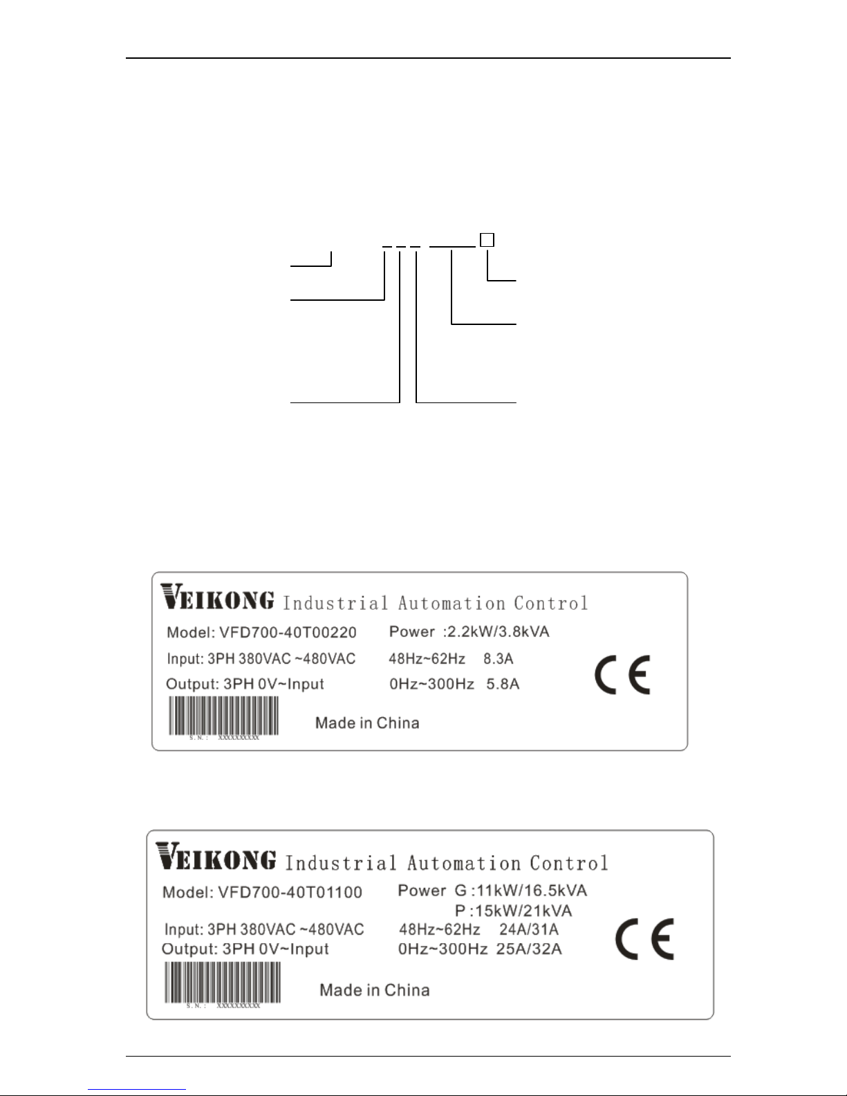
1.1 Model reference
HD700 - 4 0 T 00550
Power size
00040:0.4kW
|
45000:450kW/500kW
Input phase
D:1/3PH
T:3PH
Family
Supply voltage
2:220V
4:380V
6:690V
Brake unit
0:Built-in brake
1:No brake unit
Non: Standard G type
E: small size G type
P: small size P type
Figure1-1 VFD700 model description
1.2 Rating Label
Figure1-2 VFD700 rating label (Single power type)
VFD700

1 Technical specification
2VFD700 AC Drive Getting Started Guide
Figure1-3 VFD700 rating label (Double power type)
NOTE: Size A, B, C are single types. Size D and above are G/P types.
1.3 Power size
Power size of VFD700 is based on the standard 4 poles inductionmotor at rated voltage.
E, G: Heavy duty
P: Normal duty
Overload of E, G type: 150% rated output current, 1 minute
Overload of Ptype: 110% rated output current, 1 minute
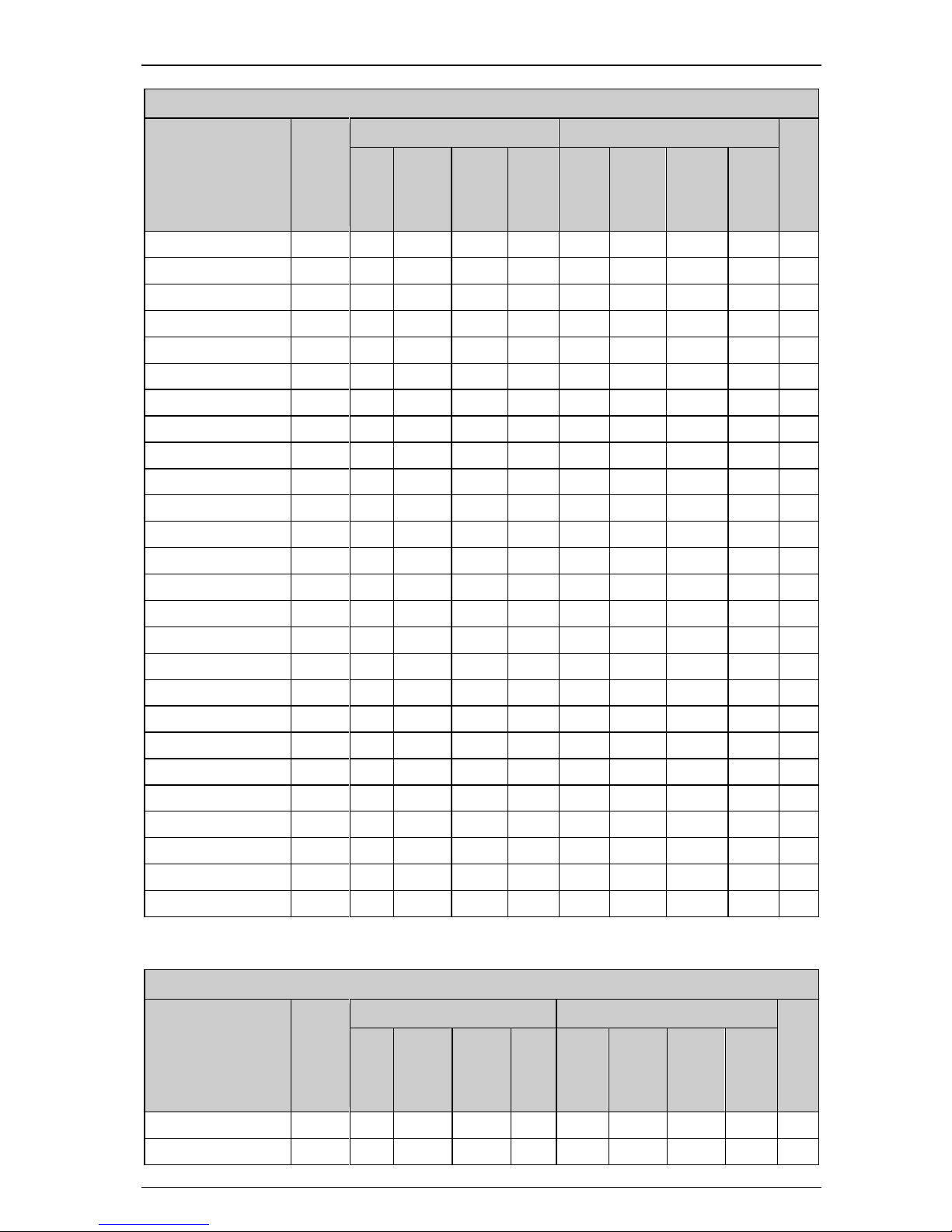
Table 1-1 220V rating data
Power supply: 200VAC~240VAC, 50Hz/60Hz, single/three phase
Model
Default carrier
frequency (kHz)
Drive
Power Size
(kVA)
Rated Input
Current(A)
Rated
Output
Current(A)
MotorP
ower(k
W)
Size
1/3PH
VFD700-20D00040
6
1.1
7.1/4
2.8
0.4
A
VFD700-20D00075
6
1.9
12.8/7.1
5
0.75
A
VFD700-20D00150
6
3.0
20.5/11.3
8
1.5
A
VFD700-20D00220
6
4.2
24/14.5
11
2.2
B
VFD700-20D00400
6
6.7
30.4/16.5
17.6
4
C
Table 1-2380V rating data
Power supply: 380VAC~480VAC, 50Hz, three phase
Model
Default
carrier
freque-
ncy
(kHz)
G
P
Size
Drive
Power
Size
(kVA)
Rated
Input
Current
(A)
Rated
Output
Current
(A)
Motor
Power
(kW)
Drive
Power
Size
(kVA)
Rated
Input
Current
(A)
Rated
Output
Current
(A)
Motor
Power
(kW)
VFD700-40T00075
6
1.7
3.6
2.5
0.75 − − − −
A
VFD700-40T00150
6
2.8
5.7
4.2
1.5 − − − −
A
VFD700-40T00220
6
3.4
6.1
5.2
2.2 A VFD700-40T00220
6
3.8
8.3
5.8
2.2 − − − − B VFD700-40T00400
6
6.3
13.2
9.5
3.7 − − − −
B
VFD700-40T00550
6
8.6
14.3
13
5.5 − − − −
B
VFD700-40T00550P
6 − − − −
8.6
14.3
13
5.5
B
VFD700-40T00550
6
8.6
12.4
13
5.5 − − − − C VFD700-40T00750
6
11
16.1
17
7.5 − − − −
C
VFD700-40T01100P
6 − − − −
15.2
21
23
11
C
VFD700-40T01100
6
16.5
24
25
11
21
31
32
15 D VFD700-40T01500
6
21
31
32
15
25
36
38
18.5
D
1 Technical specification
VFD700 AC Drive Getting Started Guide 3
Power supply: 380VAC~480VAC, 50Hz, three phase
Model
Default
carrier
freque-
ncy
(kHz)
G
P
Size
Drive
Power
Size
(kVA)
Rated
Input
Current
(A)
Rated
Output
Current
(A)
Motor
Power
(kW)
Drive
Power
Size
(kVA)
Rated
Input
Current
(A)
Rated
Output
Current
(A)
Motor
Power
(kW)
VFD700-40T01850
6
25
36
38
18.5
30
44
46
22 E VFD700-40T02200
6
30
44
46
22
40
58
60
30 E VFD700-40T03000
3
40
58
60
30
50
72
75
37
E1
VFD700-40T03700
3
50
72
75
37 − − − −
E1
VFD700-40T03000
3
40
58
60
30
50
72
75
37 F VFD700-40T03700
3
50
72
75
37
63
93
96
45 F VFD700-40T04500
3
63
93
96
45
83
121
125
55 F VFD700-40T05500
3
83
121
125
55
103
151
156
75 F VFD700-40T07500
3
103
151
156
75
119
175
180
90 F VFD700-40T09000
3
119
175
180
90
139
204
210
110
G
VFD700-40T11000
3
139
204
210
110
169
248
256
132
G
VFD700-40T13200
3
169
248
256
132
205
301
310注
160
G
VFD700-40T16000
3
205
301
310
160
231
340
350
185
J
VFD700-40T18500
3
231
340
350
185
255
375
387
200
J
VFD700-40T20000
3
255
375
387
200
280
415
427
220
J
VFD700-40T16000
3
205
301
310
160
231
340
350
185
K
VFD700-40T18500
3
231
340
350
185
255
375
387
200
K
VFD700-40T20000
3
255
375
387
200
310
457
471
250
K
VFD700-40T25000
3
310
457
471
250
343
505
520
280
K
VFD700-40T28000
3
343
505
520
280
403
592
610
315
K
VFD700-40T31500
2
403
592
610
315
444
653
673
355
K1
VFD700-40T35500
2
444
653
673
355
495
728
750
400
K1
VFD700-40T31500
2
403
592
610
315
444
653
673
355
L
VFD700-40T35500
2
444
653
673
355
495
728
750
400
L
VFD700-40T40000
2
495
728
750
400
551
810
835
450
L
VFD700-40T45000
2
551
810
835
450
622
915
943
500
L
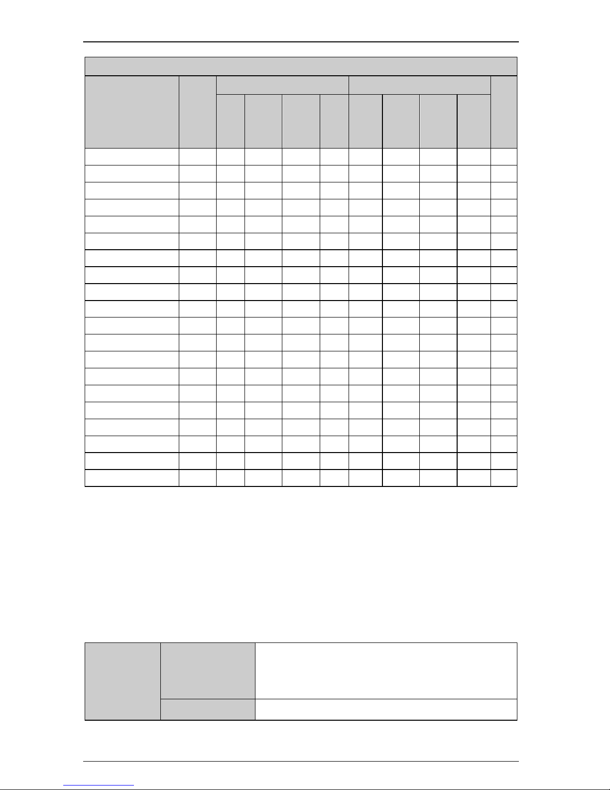
Table 1-3 690V rating data
Power supply: 500VAC~690VAC, 50Hz, three phase
Model
Default
carrier
freque-
ncy
(kHz)
G
P
Size
Drive
Power
Size
(kVA)
Rated
Input
Current
(A)
Rated
Output
Current
(A)
Motor
Power
(kW)
Drive
Power
Size
(kVA)
Rated
Input
Current
(A)
Rated
Output
Current
(A)
Motor
Power
(kW)
VFD700-60T03000
3
43
36
36
30
51
42
43
37 F VFD700-60T03700
3
51
42
43
37
65
52
54
45
F
1 Technical specification
4VFD700 AC Drive Getting Started Guide
Power supply: 500VAC~690VAC, 50Hz, three phase
Model
Default
carrier
freque-
ncy
(kHz)
G
P
Size
Drive
Power
Size
(kVA)
Rated
Input
Current
(A)
Rated
Output
Current
(A)
Motor
Power
(kW)
Drive
Power
Size
(kVA)
Rated
Input
Current
(A)
Rated
Output
Current
(A)
Motor
Power
(kW)
VFD700-60T04500
3
65
52
54
45
75
61
63
55 F VFD700-60T05500
3
75
61
63
55
103
83
86
75 F VFD700-60T07500
3
103
83
86
75
120
97
100
90 F VFD700-60T09000
3
120
97
100
90
157
127
131
110
G
VFD700-60T11000
3
157
127
131
110
179
145
150
132
G
VFD700-60T13200
3
179
145
150
132
209
170
175注
160
G
VFD700-60T16000
3
209
170
175
160
237
192
198
185
J
VFD700-60T18500
3
237
192
198
185
276
224
231
200
J
VFD700-60T20000
3
276
224
231
200
296
235
248
220
J
VFD700-60T16000
3
209
170
175
160
237
192
198
185
K
VFD700-60T18500
3
237
192
198
185
276
224
231
200
K
VFD700-60T20000
3
276
224
231
200
327
266
274
250
K
VFD700-60T25000
3
327
266
274
250
350
285
293
280
K
VFD700-60T28000
3
350
285
293
280
392
318
328
315
K
VFD700-60T31500
2
392
318
328
315
462
375
387
355
K1
VFD700-60T35500
2
462
375
387
355
509
413
426
400
K1
VFD700-60T31500
2
392
318
328
315
462
375
387
355
L
VFD700-60T35500
2
462
375
387
355
509
413
426
400
L
VFD700-60T40000
2
509
413
426
400
576
468
482
450
L
VFD700-60T45000
2
576
468
482
450
651
529
545
500
L
NOTE:
VFD700-Ч1TЧЧЧЧЧ rating data are the same with VFD700-Ч0TЧЧЧЧЧ.
For 30kW and above models, internal bake unit is optional, please refer to chapter 1.1.
When VFD700-xxT13200 or VFD700-xxT28000 is used as P type, the default carrier
frequency is 1kHz.
1.4 General technical data
Table 1-4 General technical specification
Input Power
Input Voltage U
in
200V (−10%)~240V (+10%) 1/3 PH
380V (−10%)~480V (+10%) 3PH
500V (−10%)~690V (+10%) 3PH
Input Frequency
50/60Hz (±2Hz)
1 Technical specification
VFD700 AC Drive Getting Started Guide 5
Maximum Supply
Imbalance
≤3%
Power Output
Output Voltage
0V~Uin
Output Frequency
0Hz~300Hz
Main
PerformanceF
unction
Voltage Control
V/F, Open loop Vector Control
Switching
Frequency
1kHz~15kHz
SpeedAdjustment
Range
Open loop vector -1:100, V/F mode -1:50
Start Torque
0.5Hz: 100% rated torque, 1Hz: 150% rated torque
Torque Accuracy
7%
Reference
resolution
Digit- 0.01Hz, Analogue- 0.1%×Max. frequency
Acce. & Dece. rate
0.1s~3600min
Voltage Boost
0.1%~30.0%
Overload
E, G type:150% rated output current, 1 minute
P type:110% rated output current, 1 minute
V/F
4 types: V/F(user can program) and ramp (2.0 power, 1.7
power, 1.2 power)
DC Braking
Injection frequency: 0.0%~100.0% Max. frequency
Injection current: 0.0%~300.0% rated current
Injection time: 0.00s~60.00s
Dynamic Brake
Brake rate: 0.0%~100.0%
Jog
Jog frequency: 0.00Hz~maximum frequency
Jog acceleration rate: 0.1s~600.0s
Jog interval time: 0.1s~600.0s
Preset
16 preset speeds (decided by control terminals)
AVR
Maintain the rated output voltage when the input power
supply voltage changed
Special
Function
Textile
For textile machine control
Simple PLC
Onboard PLC
Length Control
Winding control
PID Control
Process control(reference close loop control)
1 Technical specification
6VFD700 AC Drive Getting Started Guide
Advanced
Function Blocks
2 logic control blocks, 1 binary selector, 2 threshold control
blocks, 3 variable selectors
Control
Terminal
Reference Source
Digit: Keypad, motorized pot (E-Pot), preset speed, pulse,
comms.
Analogue: AI1: 0V~10V, 0(4) mA~20mA;
AI2: 0V~10V
Operating Mode
Keypad, Control terminal, Serial comms.
DigitalInput
Terminals
DI1~DI7: Programmable terminals and DI6 can be set as
pulse input, 0Hz~60Hz; DI7 can be high frequency pulse
input(1kHz~50.0kHz)or PTC thermistor input
Digital output
terminals
DO1~DO2: Programmable terminals, Max. output
current:50mA, DO2can be the terminal of output
pulse( 0.1kHz~50.0kHz ), and output PWM
Analogue output
AO1: programmable terminal, 0V~10V
Status relay
2 programmable relays, contactor data:
AC250V/2A(COSφ=1)
AC250V/1A(COSφ=0.4)
DC30V/1A
Comms.
Connector
2 terminals(A&B) and RJ45 Port
Protocol
ModbusRTU
Environment
Altitude
1000m rated
1000m~3000m,1% rated current derating per 100m
Operating
Temperature
−10C~+40C
Max. Humidity
≤90%RH, no-condensing
Vibration
≤5.9m/s
2
(0.6g)
Storage
Temperature
−40C~+70C
Running
Environment
Indoor, no-flammable or corrosive gasses,no contamination
with electrically conductive materials,avoiding dust which
may restrict the fan

1 Technical specification
VFD700 AC Drive Getting Started Guide 7
Optional Module
LCD keypad, HDOM-232, HDOM-USB, Profibusmodule,
keypad pallet, HDSOFT (PCTools), etc.
Protection Function
Output shortage, over current, over load, over voltage,
under Voltage, Phase loss, over heat (heatsink and
junction), external fault, etc.
Efficiency
1.5kW and below: ≥89%
2.2kW~22kW: ≥93%
30kW and above: ≥95%
Installation
can be installed by hanging wall, through holes, or
vertically
Ingress Protection
IP20, IP21 (by adding optional device)
Cooling Method
220V/0.4kWmodel – cools naturally, others cool with
forced air cool
2 Installation and cabling
8VFD700 AC Drive Getting Started Guide
2 Installation and cabling
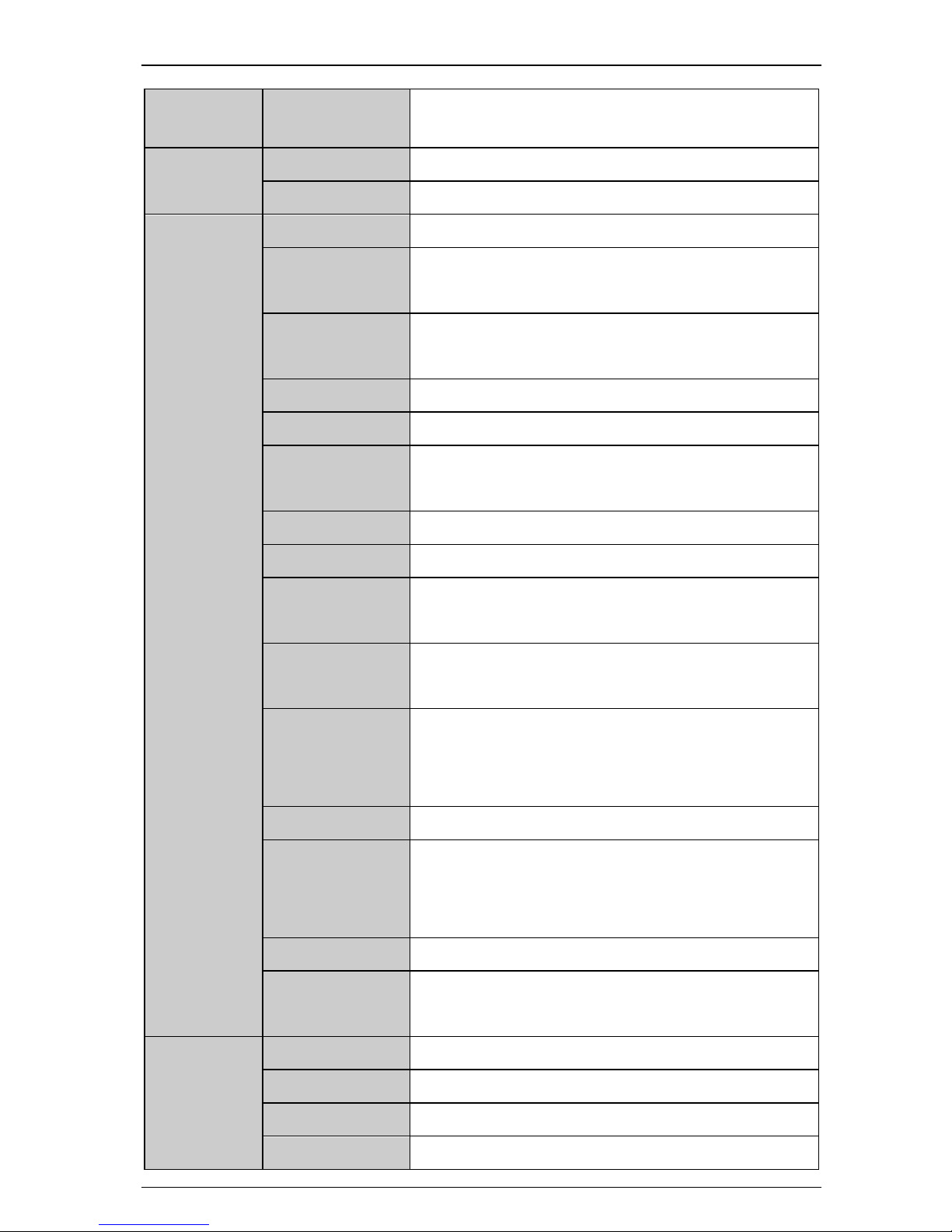
2.1 Dimension
2.1.1 Parts of drive
Figure 2-1 Parts of VFD700 drive
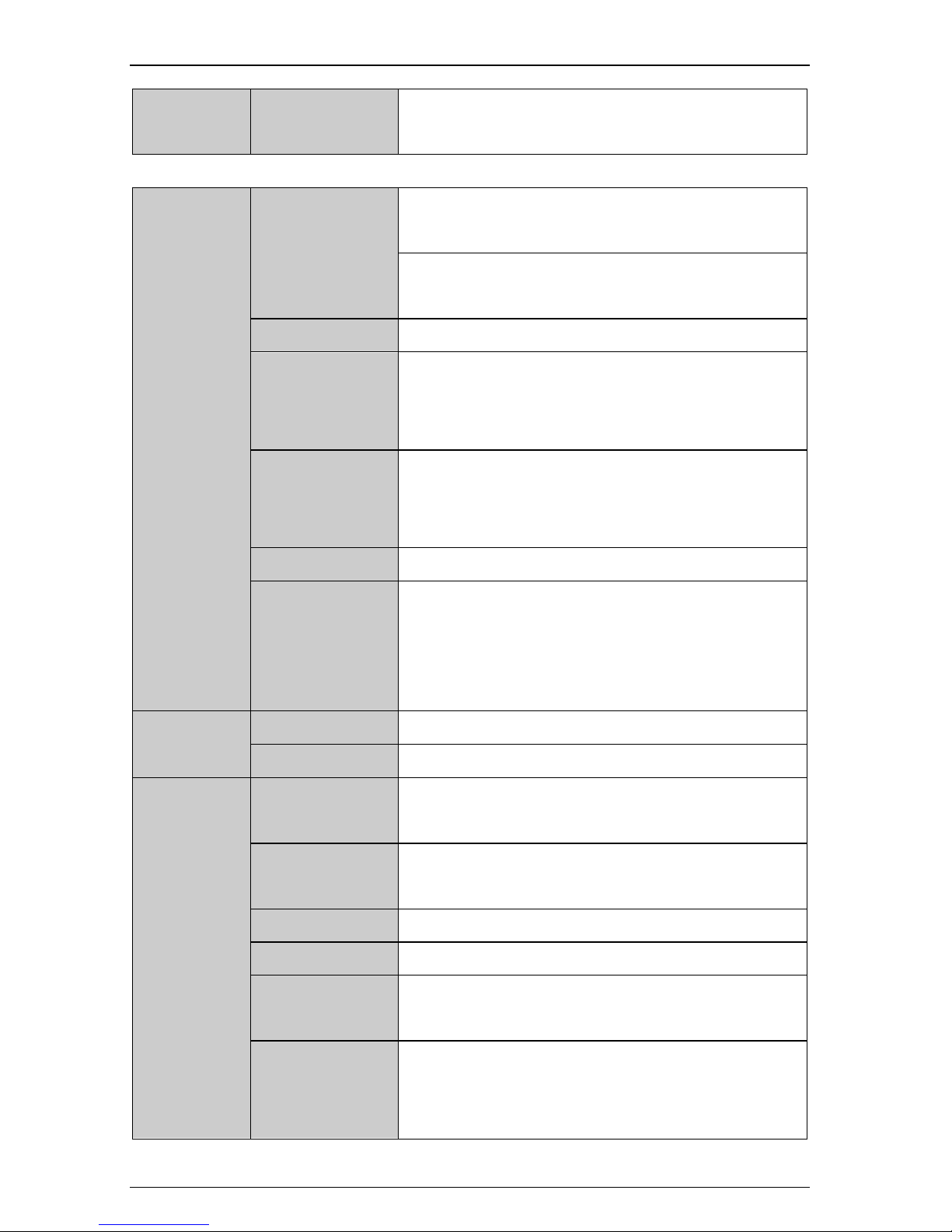
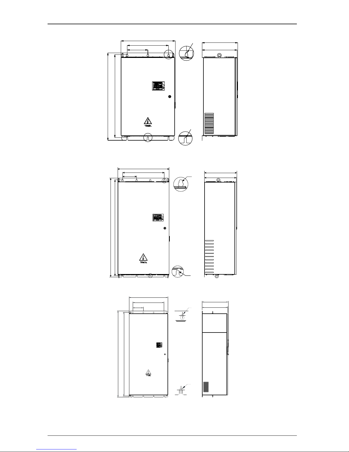
2.1.2Diagram of mounting
Ø
Ø
D
W
W1
H
H1
Figure 2-2 Mechanical dimensions and mounting (Size A, B, C)
EMC filter Link
Terminal Cover
Rating Label
Fan
Power Terminals
Option Connector
Control Terminals
RS485 Port
Keypad
Keypad Connector
Barcode
2 Installation and cabling
VFD700 AC Drive Getting Started Guide 9
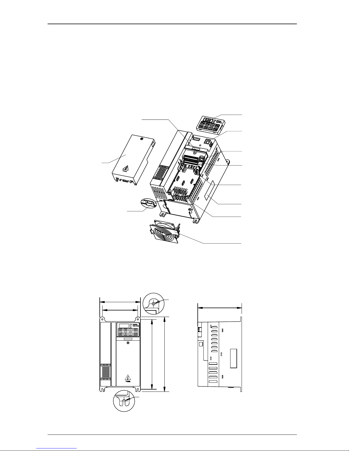
D
W
W1
W2
Ø
Ø
H1
H
Figure 2-3Mechanical dimensions and mounting (Size D, E)
Ø
W
W1
Ø
D
D1
H
H1
Figure 2-4Mechanical dimensions and mounting (Size E1, F)
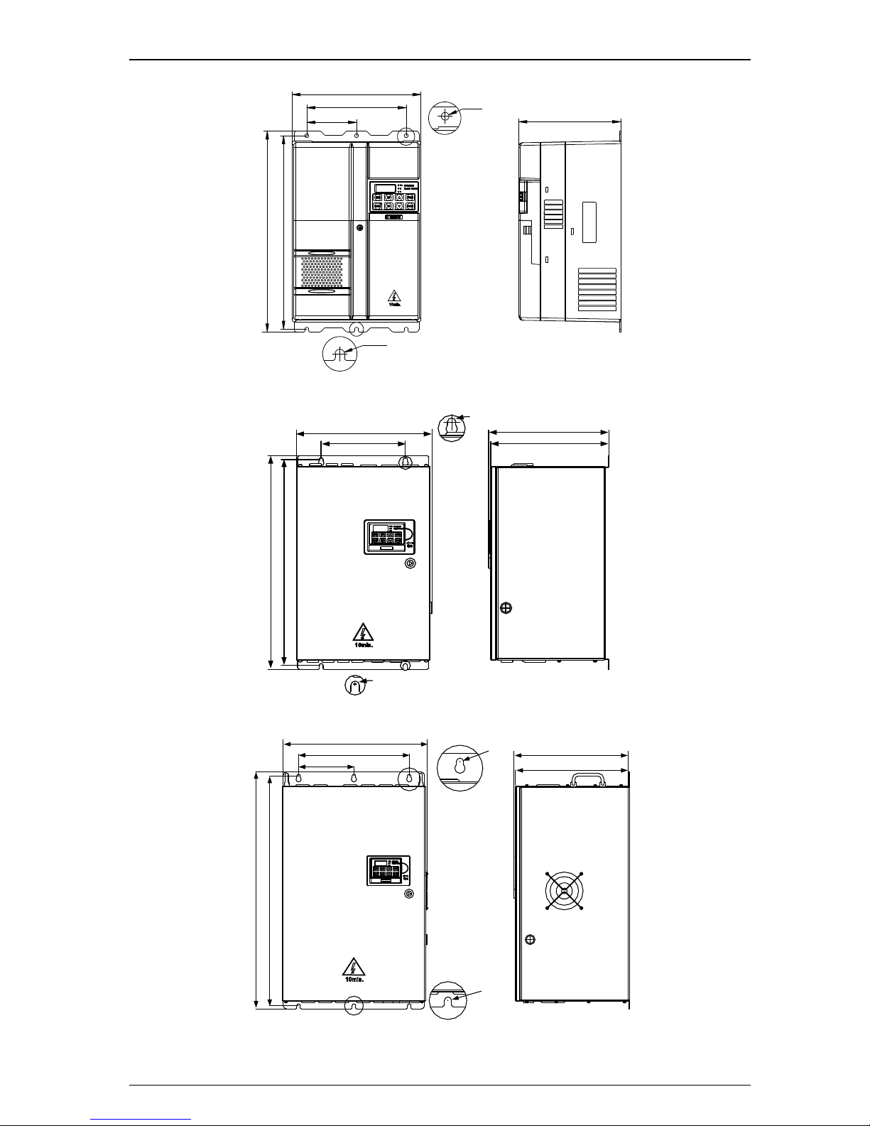
W
W1
W2
Ø
Ø
H
H1
D
D1
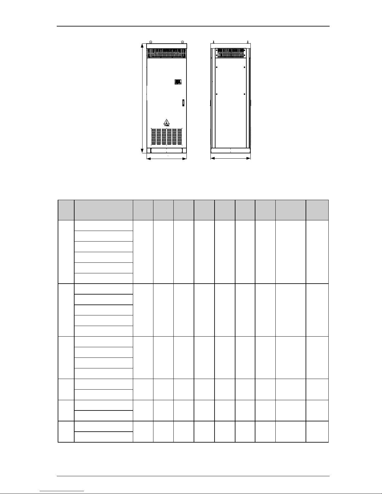
Figure 2-5Mechanical dimensions and mounting (Size G)
VEIKONG
VFD700
VEIKONG
VFD700
2 Installation and cabling
10VFD700 AC Drive Getting Started Guide
W
W1
W2
D
D1
H
H1
Ø
Ø
Figure 2-6Mechanical dimensions and mounting (Size J)
W
W1
W2
H
H1
D
D1
Ø
Ø
Figure 2-7Mechanical dimensions and mounting (Size K)
D1
W2
H1
W
W1
H
D
Ø
Ø
Figure 2-8 Mechanical dimensions and mounting (Size K1)
VFD700
VEIKONG
VEIKONG
VEIKONG
VFD700
VFD700
2 Installation and cabling
VFD700 AC Drive Getting Started Guide 11
H
W
D
Figure 2-9Mechanical dimensions and mounting (Size L)
Table 2-1 Mechanical dimensions
Size
Model Name
W
(mm)
W1
(mm)
W2
(mm)
H
(mm)
H1
(mm)
D
(mm)
D1
(mm)
Mounting
Hole Ø
Weight
(kg)
A
VFD700-20D00040
97.4
80 − 202.4
190
148.8 − 5
1.4
VFD700-20D00075
VFD700-20D00150
VFD700-40T00075
VFD700-40T00150
VFD700-40T00220
B
VFD700-20D00220
142.4
123.5
−
220.4
208
155.5 − 5
2.2
VFD700-40T00220
VFD700-40T00400
VFD700-40T00550
VFD700-40T00550
C
VFD700-20D00400
163.1
142 − 300
280
176.8 − 6
4.5
VFD700-40T00550
VFD700-40T00750
VFD700-40T01100P
D
VFD700-40T01100
238.5
184
92
370
356.5
189 − 7
8.8
VFD700-40T01500
E
VFD700-40T01850
238.5
184
92
435.5
422
200.3 − 7
12.1
VFD700-40T02200
E1
VFD700-40T03000
320
210 − 510
490
226
222.5 8 20
VFD700-40T03700
VFD700
VEIKONG
2 Installation and cabling
12VFD700 AC Drive Getting Started Guide
Size
Model Name
W
(mm)
W1
(mm)
W2
(mm)
H
(mm)
H1
(mm)
D
(mm)
D1
(mm)
Mounting
Hole Ø
Weight
(kg)
F
VFD700-40T03000
355.5
221 − 573
552.5
315.5
310
10
40
VFD700-40T03700
VFD700-40T04500
VFD700-40T05500
VFD700-40T07500
VFD700-60T03000
VFD700-60T03700
VFD700-60T04500
VFD700-60T05500
VFD700-60T07500
G
VFD700-40T09000
445.6
340
170
725
701.5
355
349.5
10
63
VFD700-40T11000
VFD700-40T13200
VFD700-60T09000
VFD700-60T11000
VFD700-60T13200
J
VFD700-40T16000
575.5
440
220
937
889
379.3
373.8
13
104
VFD700-40T18500
VFD700-40T20000
VFD700-60T16000
VFD700-60T18500
VFD700-60T20000
K
VFD700-40T16000
640
520
175
1246.5
1207.5
405.5
400
13
150
VFD700-40T18500
VFD700-40T20000
VFD700-40T25000
VFD700-40T28000
VFD700-60T16000
VFD700-60T18500
VFD700-60T20000
VFD700-60T25000
VFD700-60T28000
2 Installation and cabling
VFD700 AC Drive Getting Started Guide 13
Size
Model Name
W
(mm)
W1
(mm)
W2
(mm)
H
(mm)
H1
(mm)
D
(mm)
D1
(mm)
Mounting
Hole Ø
Weight
(kg)
K1
VFD700-40T31500
720
579
194
1595.5
1553.5
483
477.5
13
−
VFD700-40T35500
VFD700-60T31500
VFD700-60T35500
L
VFD700-40T31500
804
−
−
2200
−
804
−
−
350
VFD700-40T35500
VFD700-40T40000
VFD700-40T45000
VFD700-60T31500
VFD700-60T35500
VFD700-60T40000
VFD700-60T45000
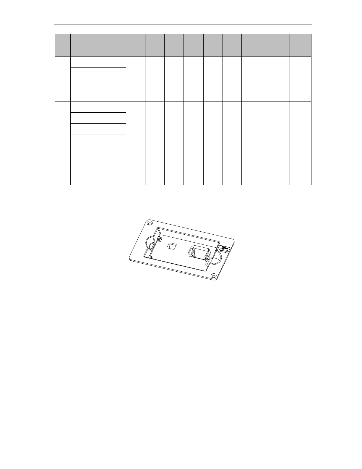
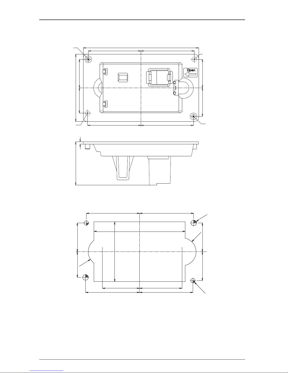
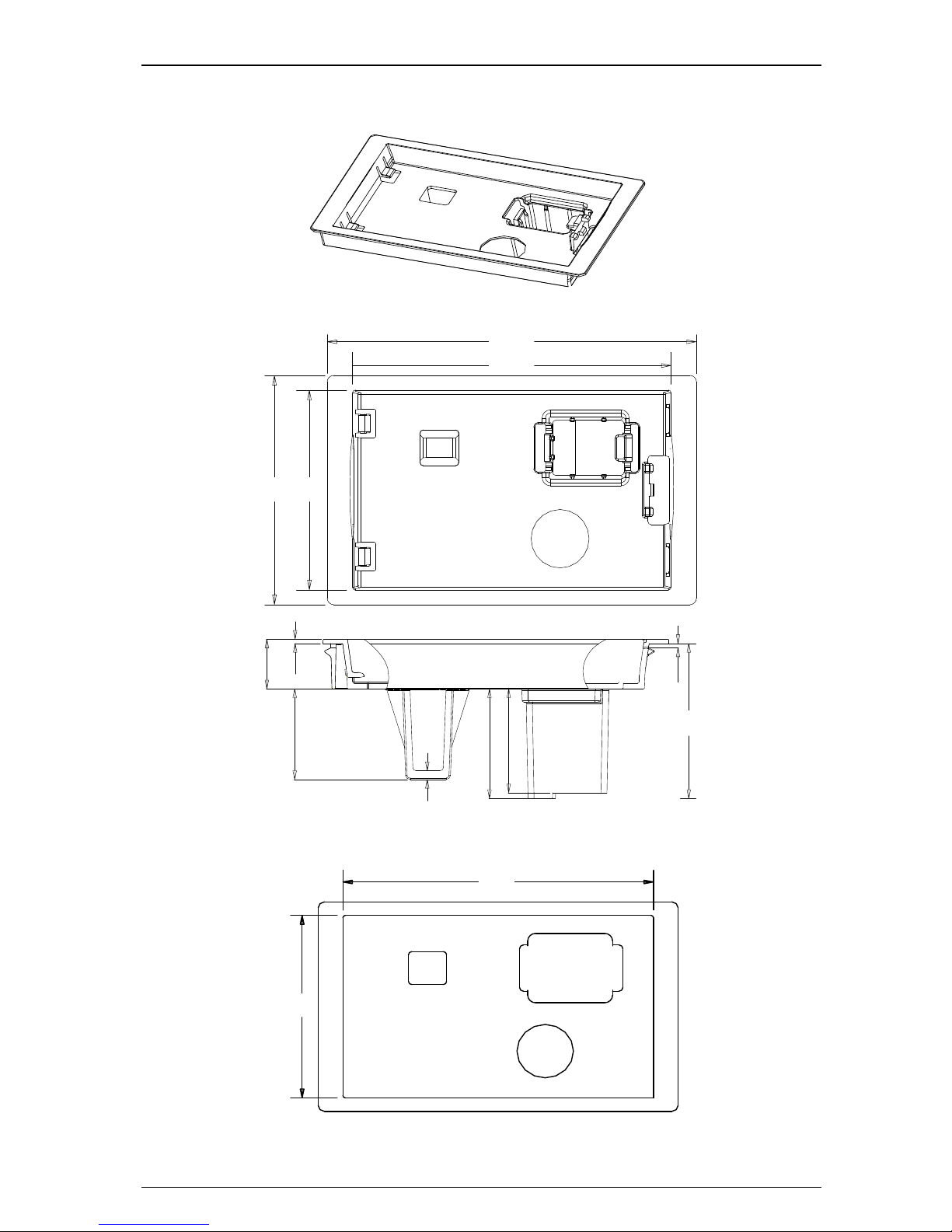
2.1.3Keypad pallet
Figure 2-10Outlook of keypad palle
2 Installation and cabling
14VFD700 AC Drive Getting Started Guide
Diagram of pallet dimensions and mounting
36
6667
36
6766
32
36
145
85
54.5
3
Mounting hole for countersunk
head phillips slot screw
GB/T819.1M4*12
Location pillar Ø 6
Mounting hole for countersunk
head phillips slot screw
GB/T819.1M4*12
Location pillar Ø 6
Figure 2-11Outline dimensions of pallet
32 36
36 36
66 67
46 52.5
R
17.7
R
17
.
5
113
74.7
67 66
2
−
Ø
7
2
−
Ø
5
.
5
Figure 2-12mounting dimensions of pallet
2 Installation and cabling
VFD700 AC Drive Getting Started Guide 15
2.1.4 Simple keypad pallet
Figure 2-13Outlook of Simple keypad pallet
114.7
105.6
64.570.6
53.0
31
37.5
35.5
1.5
1.5
17
3
Figure 2-14Outline dimensions of simple keypad pallet
106.6
65.5
Figure 2-15Mounting dimensions of Simple keypad pallet
2 Installation and cabling
16VFD700 AC Drive Getting Started Guide
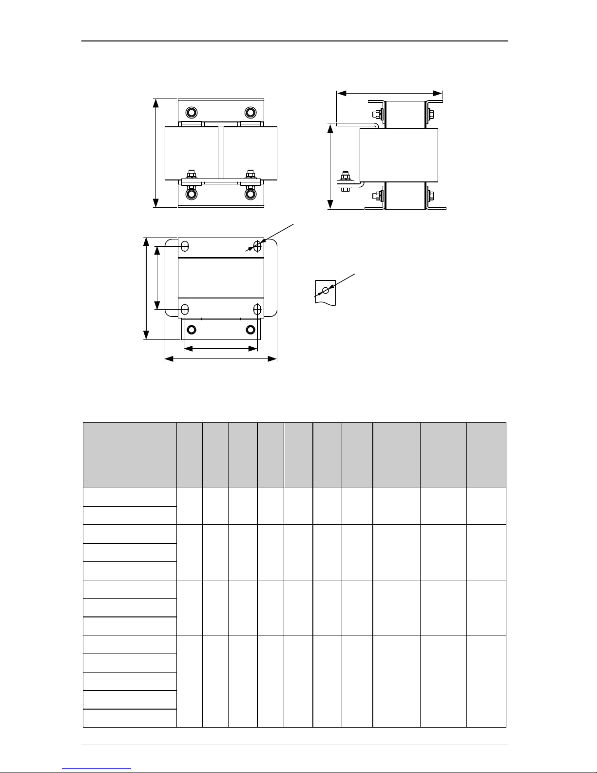
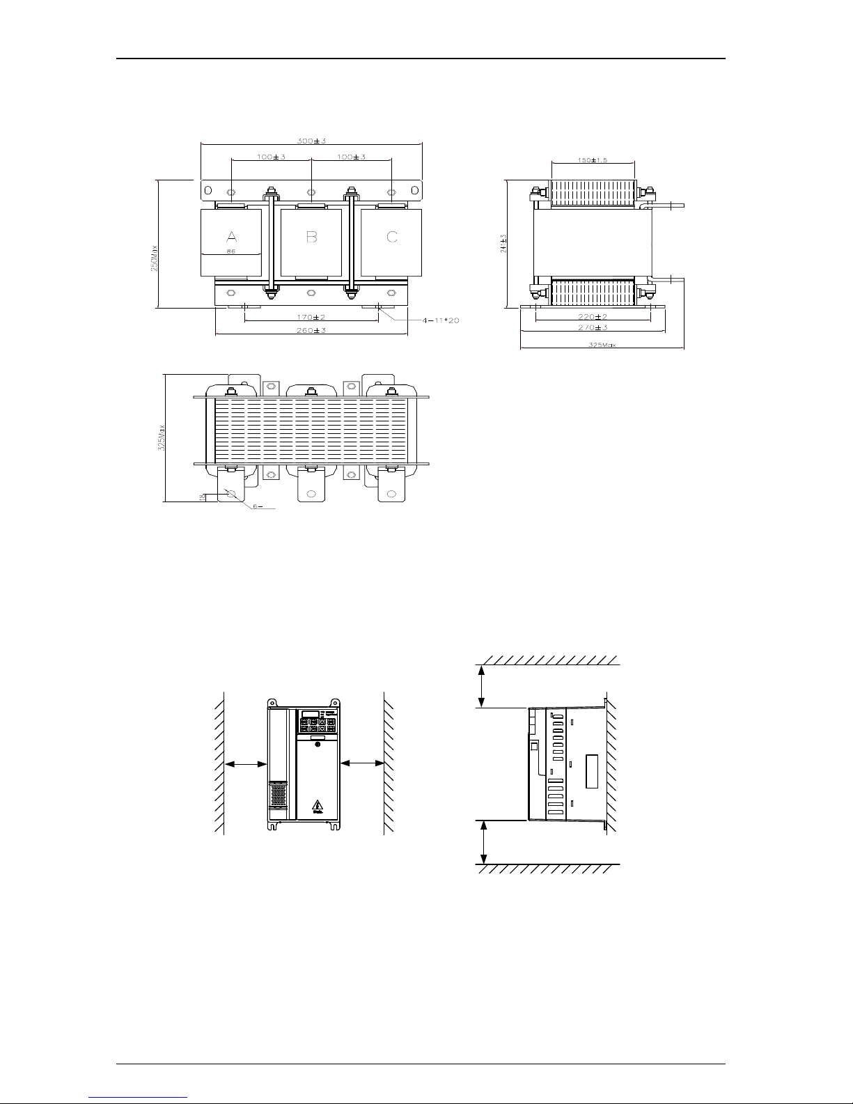
2.1.5 External DC reactor dimensions
Copper bar:30*4.0mm
w1
w
d1
d
h1
f
h
2
-
K
4
-
R
*
L
Figure 2-16 External DC reactor dimensions
Table 2-2 380V DC reactor dimensions (Unit: mm)
Model
w
w1 d d1 h h1
f
Mounting
hole
R*L
Copper
bar
mounting
hole
K
Reactor
weight
(kg)
VFD700-40T05500
167
108
153.5
95
163.5
131
158.5
10×15
Ø9
10.3
VFD700-40T07500
VFD700-40T09000
190
160
153
117
245
192
180
10×15
Ø12
20
VFD700-40T11000
VFD700-40T13200
VFD700-40T16000E
190
160
148
115
245
192
250
10×20
Ø13
25
VFD700-40T18500E
VFD700-40T20000E
VFD700-40T16000
275
210
240
205
235 − 240
11×18
Ø14
38
VFD700-40T18500
VFD700-40T20000
VFD700-40T25000
VFD700-40T28000
2 Installation and cabling
VFD700 AC Drive Getting Started Guide 17
Table 2-3 690V DC reactor dimensions (Unit: mm)
Model -
w
w1 d d1 h h1
f
Mounting
hole
R*L
Copper
bar
mounting
hole
K
Reactor
weight
(kg)
VFD700-60T05500
128
100
116
90
180
140
175
10×15
Ø9
10
VFD700-60T07500
VFD700-60T09000
190
160
153
117
245
192
180
10×15
Ø12
20
VFD700-60T11000
VFD700-60T13200
VFD700-60T16000
190
160
148
115
245
192
250
10×20
Ø13
25
VFD700-60T18500
VFD700-60T20000
VFD700-60T16000
235
180
230
175
205 − 230
11×18
Ø14
27.5
VFD700-60T18500
VFD700-60T20000
VFD700-60T25000
VFD700-60T28000
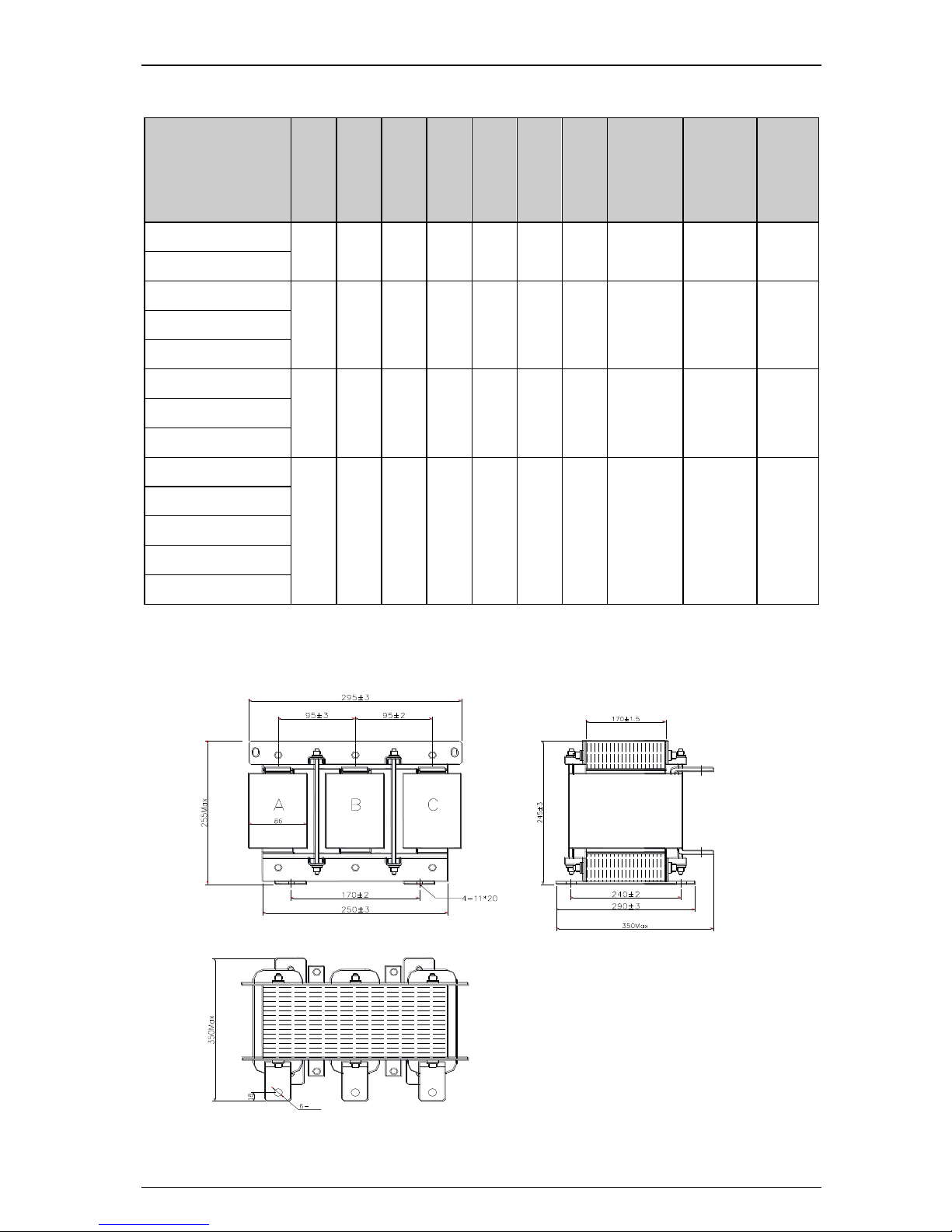
Note: 1.Reactors of VFD700-40T31500E and VFD700-40T35500E are AC Reactor, whose
dimensions are as follows:
Figure 2-17 Dimensions of Externeal AC Reactor (Size K1,380V_)
13
Φ
2 Installation and cabling
18VFD700 AC Drive Getting Started Guide
Note: 2.Reactors of VFD700-60T31500E and VFD700-60T35500E are AC Reactor, whose
dimensions are as follows:
Φ
13
Figure 2-18 Dimensions of Externeal AC Reactor (Size K1,690V_)
2.2 Mechanical installation
2.2.1Drive installation diagram
L
L
H
H
Figure 2-19Single drive installation
Recommending: L≥50mm, H≥50mm
2 Installation and cabling
VFD700 AC Drive Getting Started Guide 19
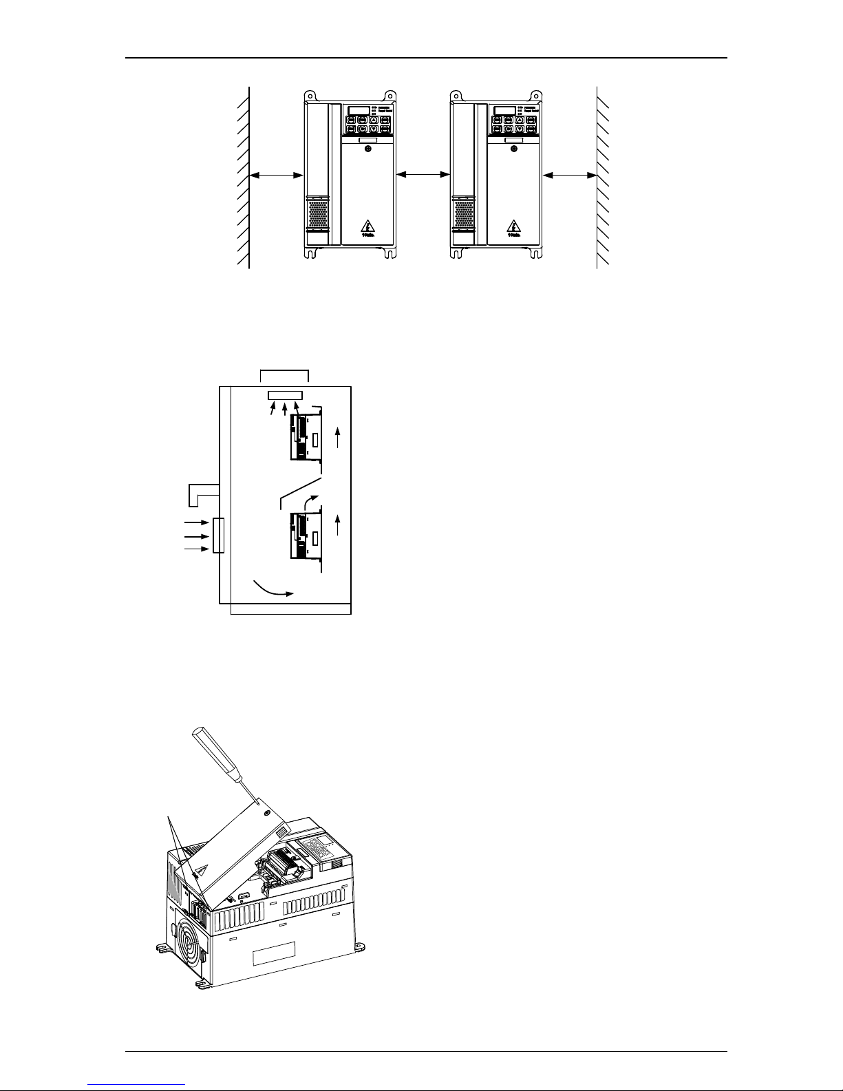
L
L
L
Figure 2-20Multi-drives installation
Recommending: L≥50mm
Figure 2-21 Multi drives vertical installation
NOTE:In vertical installations where drives
aremounted above each other, there should
besuitable air flow to keep the drives cool.
Air flowshould be drawn in and expelled as
illustrated inthe left picture.
2.2.2 How to fit and remove the terminal cover
Hz
PROGMODE
A Keypad Control
V
ESC
PRO
MOD
RU
N
STO
P
Clips
Remove: Untighten the screw, loose the
clip then take off the cover.
Fit: at a suitable angle, put the clips into
the slots on the middle cover, push the
coveron, tighten the screw M4×10
(Torque 1N·m).
Figure 2-22 Terminal cover fitting and removes
VEIKON
VFD700
VEIKONG
VFD700
VEIKONG
VFD700
2 Installation and cabling
20VFD700 AC Drive Getting Started Guide
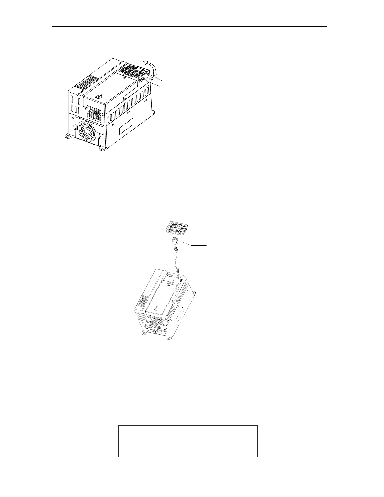
2.2.3How to fit and remove the keypad
Figure 2-23 Diagram of the keypad fitting
and removing
Remove: push the spring clip, and then
pull up the keypad.
Fit: fit the left two clips (at correct angle)
into the slots on the control pod, and then
push down the keypad.
VFD700 keypad is removable, and can be linked to the drive with a standard net cable , shown
as below:
port converter
Figure 2-24 Keypad with cable
NOTE: The maximum length of cable is 10m.
2.3 Electrical installation
2.3.1Power terminals
Models of size A, B, C: VFD700-20D00040~VFD700-40T00750
L1 L3/NL2
U
V
W
PE +DC +DC1
−DC
BR PE
Figure 2-25 Size A, B power terminals layout
2 Installation and cabling
VFD700 AC Drive Getting Started Guide 21
L1
L3L2 U
V
W
PE +DC
−DC
BR PE
Figure 2-26 Size C power terminals layout
Table 2-4 Power terminal functions of size A, B, C
Terminals
Functions
L1, L2, L3/N
AC power supply.For single phase supply, L1and L3/N are
suggested
+DC, +DC1
For DC reactor, linked by terminal
BR
Brake resistor, the other side of the resistor is connected to
+DC1
−DC
Negative DC bus
U, V, W
Output terminals(Motor terminals)
PE
Protective earth terminal
NOTE:
Size C has DC reactor inside, +DC1 is not used.
For size C, the brake resistor is connected to BR and +DC.
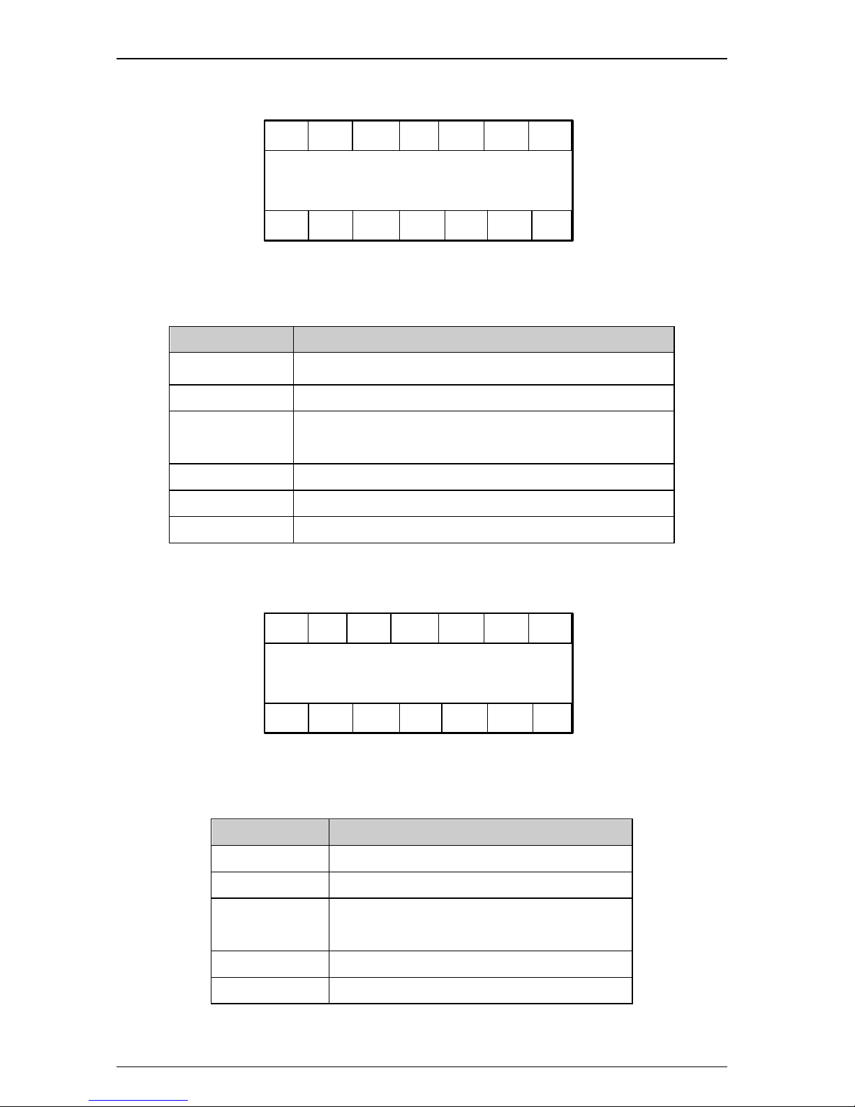
Models of size D, E: VFD700-40T01100~VFD700-40T02200
L1
L3L2 U V WPE PE+DC
−DC
BR
Figure 2-27 Size D, E power terminals layout
Table 2-5 Power terminal functions of size D, E
Terminals
Functions
L1, L2, L3
AC power supply
+DC, −DC
Positive and negative DC bus
BR
Brake resistor, the other side of the resistor is
connected to +DC
U, V, W
Output terminals (Motor terminals)
PE
Protective earth terminal
2 Installation and cabling
22VFD700 AC Drive Getting Started Guide
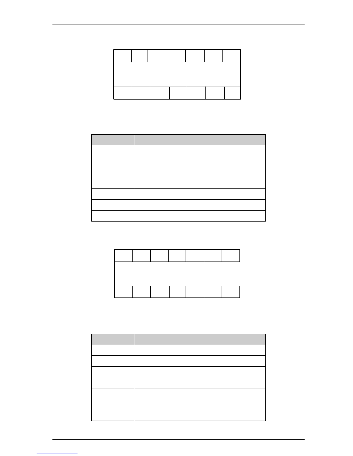
Models of size E1: VFD700-××T03000E~VFD700-××T03700E
L1 L2 L3
PE
U V W
+DC
-DC
BR
Size E1
PE
+
DC +DC1
Figure 2-28 Size E1 power terminals layout
Table 2-6 Power terminal functions of size E1
Terminals
Functions
L1, L2, L3
AC power supply
+DC, +DC1
For DC reactor, linked by busbar from factory
BR
Brake resistor, the other side of the resistor is connected to
+DC
−DC
Negative DC bus
U, V, W
Output terminals (Motor terminals)
PE
Protective earth terminal
Models of size F: VFD700-××T03000~VFD700-××T04500
L1 L2 L3
PE U V W+DC
-DC
BR
Size F
PE
Figure 2-29 Power terminal of size F
Table 2-7 Power terminal of size F
Terminals
Function
L1, L2, L3
AC power supply
+DC, −DC
Positive and negative DC bus
BR
Brake resistor, the other side of the resistor is
connected to +DC
U, V, W
Output terminals (Motor terminals)
PE
Protective earth terminal
2 Installation and cabling
VFD700 AC Drive Getting Started Guide 23
Models of size F: VFD700-××T05500~VFD700-××T07500
L1 L2 L3PE
PE U V W+DC
-DC
BR
Size F
+DC +DC1
Figure 2-30 Power terminal of size F
Table 2-8 Power terminal of size F
Terminals
Function
L1, L2, L3
AC power supply
+DC, +DC1
For DC reactor
BR
Brake resistor, the other side of the resistor is
connected to +DC1
−DC
Negative DC bus
U, V, W
Output terminals(Motor terminals)
PE
Protective earth terminal
Models of size G: VFD700-××T09000~VFD700-××T 13200
L1 L2 L3 PE
PEU V W
+DC
-DC
BR
Size G
+DC +DC1
Figure 2-31 Power terminal of size G
Table 2-9 Power terminal functions of size G
Terminals
Function
L1, L2, L3
AC power supply
+DC, +DC1
For DC reactor
BR
Brake resistor, the other side of the resistor is
connected to +DC
−DC
Negative DC bus
U, V, W
Output terminals(Motor terminals)
PE
Protective earth terminal
 Loading...