

Veikong VFD500-PV Series Operation Manual

Operation manual
VFD500-PV Series
Solar pumping Inverter
Solar pumping inverter user manual
220V
380V
Max input DC voltage
450V
810V
Recommended MPPT voltage range
150~410VDC
250~800VDC
Recommended input voltage
305V
530V
MPPT efficiency
>99%
Input channel
2
Rated output voltage
1/3-phase 220VAC
3-phase 380-480VAC
Output frequency range
0~60Hz
Max efficiency of the machine
99%
Ambient temperature range
-10 °C~50 °C, derating if the temperature is above 40 °C
Cooling method
Air cooling
Protection degree
IP20/IP21
Altitude
Below 1000m; above 1% for every additional 100m.
Standard
CE
1、Electrical cable Connection
Please follow the diagram below for wiring. And pay attention to the following issues:
The power output of the PV panel is connected to the “+” and “-” terminals. Please note that the
polarity is not reversed.
Make sure that the inverter input AC voltage level is consistent with AC grid voltage before connecting
with Input “R”, “S” and “T” terminals
If Grid is single-phase power supply, you can connect to R T or any two terminals of “R”, “S” and “T”。
DI1 defaults to the running terminal input.
AI2 defaults to the water tank level detection signal input, which is used to control the inverter
sleep and auto start.
Relay 1 output defaults to the fault signal output.
1.1 Electrical Specifications
Table 1-3 Electrical Specifications
Noted: We suggest solar panel power should be 1.2-1.35 times higher than solar pump power ,and solar
pump inverter power should be same or higher level than solar pump. When solar pump distance to
inverter higher than 100m,it should be equipped with Output reactor or higher level power inverter .for
Solar pane,l total VOC less than Maximum DC voltage of inverter and Solar panel vmp is recommend 530V
for 380V pump and 305V for 220V pump
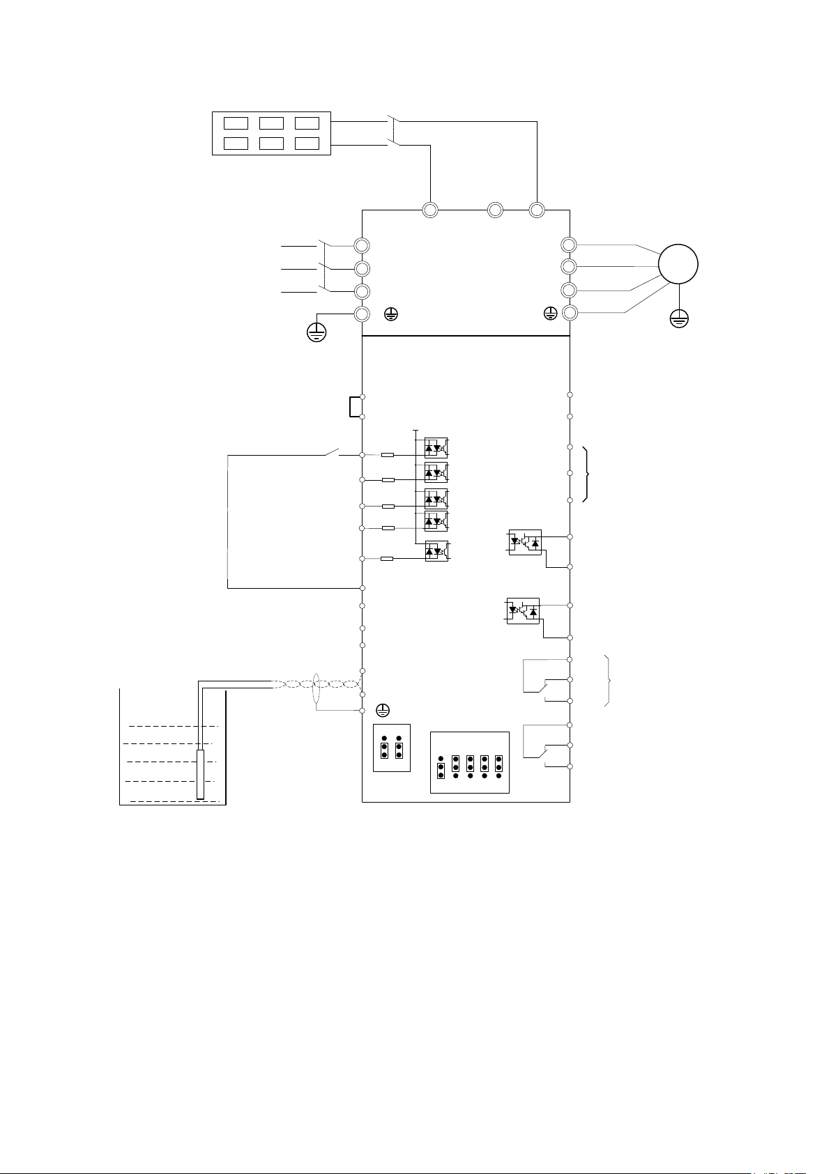
M
U
V
W
R
S
T
3 phase power
input
DI1
DI2
DI3
DI4
COM
AI1
AI2
GND
485+
485-
RS485 port
AO2
GND
AO1、AO2 output:
0~10V/0~20mA
DO1
COM
T1A
T1C
T1B
+10V
PLC
+24V
+24V
-
+
PB
HDI
HDO
COM
AO1
Water tank level
feedback
Relay 1 output,
Default is fault signal
output
485
ON
OFF
AI1VAI2
V
I I I I
AO1VAO2
V
ON ON
OFF OFF
Grounding
Connector slip
GND
Main circuit
Control circuit
Q2
Solar panels
Q1
Start/stop
terminal
Wire Diagram of solar pump inverter

2、Trial run(How to start solar pump inverter)
Make sure all cables connections of solar panel and pump motor correct and no
need to set any parameter,if you want to set parameter ,you can do as follows
Step 1: Keypad control:Set motor parameter P11.02- P11.06 If dry run protection is
required, measure the unload protection current according to the following method. If dry
run protection not required then go to step 2
Notice”Unload detection current self-learning: disable the PV pump function
(P47.00=0), run to 30~40Hz, when the output frequency is stable, enter P24.13, press
the keyboard and simultaneously for more than 2 seconds, then P24.13
value will change automatically. In this process, the pump no need to take out from
water
Step 2: Set other related special solar pump parameters for optimization
Step 3: After trial run finishing, If pump still not pump water when inverter is running
more than 40 Hz.,Please disconnect the power supply and replace any two-phase wiring of
the motor.
3、Keypad display
3.1 Monitor display
According to the running status of the inverter, the digital tube displays different
contents in turn. If the button has no operation, the next monitoring amount is
automatically displayed every few seconds; of course, you can also switch to the
next monitoring indicator
When the inverter is in the stop state, the digital tube is cyclically scrolling to
display:
“00000”DC bus voltage(r27.03)given frequency(r27.01) Distance
remaining time(r47.02)“00000”
When the inverter is in running state, the digital tube is cyclically scrolling to
display.:
“00000”DC bus voltage(r27.03)output frequency(r27.00)output current
(r27.06)output power(r16.02)“00000”
When the inverter is in a fault state, the digital tube is cyclically scrolling to
display.:
Fault code (r25.00) DC bus voltage at fault (r25.03) Output frequency at
fault (r25.01) Output current at fault (r25.02) Output power at fault (r25. 16)
fault code
3.2 Menu mode
After the inverter is power on, the keyboard menu mode is user-defined mode. Most
of users only need to pay attention to the parameters displayed in this mode. To check
the complete inverter parameters, press the and keys while the keyboard is
displayed . When the keyboard is displayed , press the key
alarm code
meaning
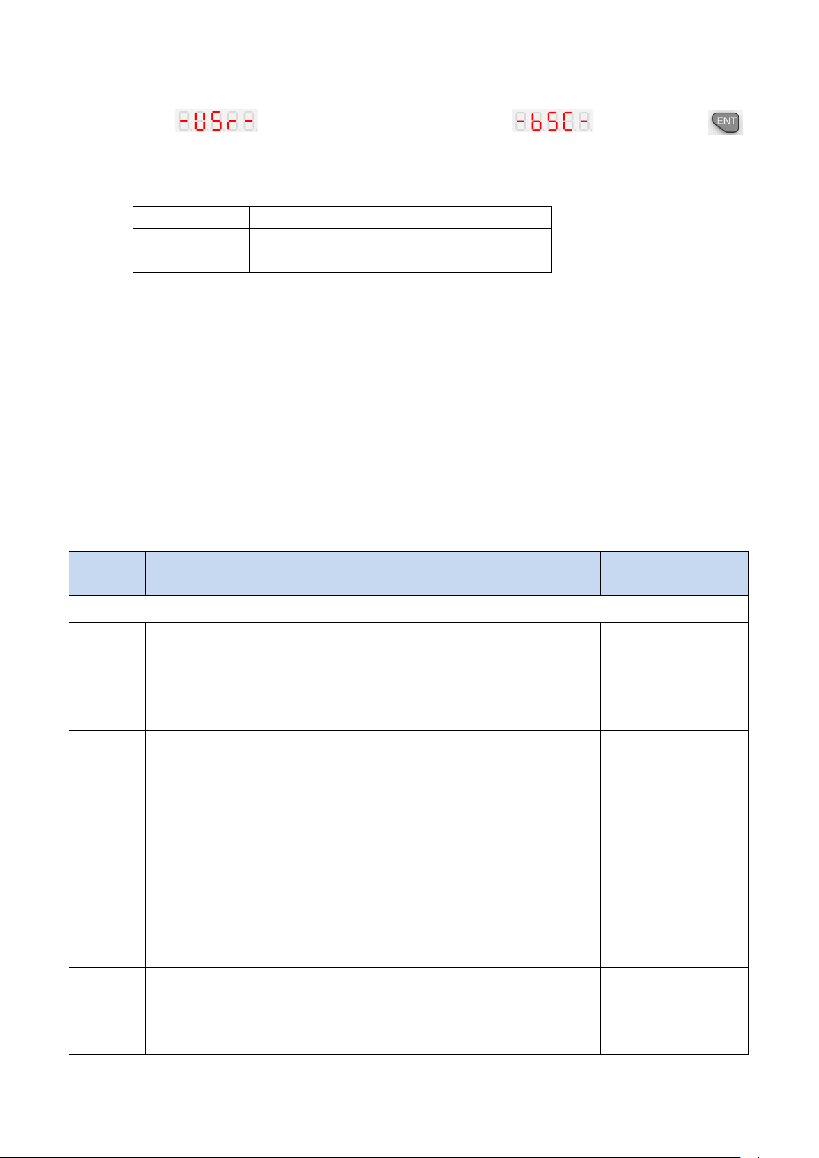
Er.CCC
Light weak fault, please refer to
function code P47.05~P47.07
Function
code
Name
Description
Default
Propert
y
47 Group solar pumping special group
P47.00
Solar pump function
enable
0: invalid
The parameters behind the 47 group cannot
be changed!
1: Enable, to enable the special function of
the PV pump inverter
1
★
P47.01
Solar pump control
mode
Units digit’s: Startup mode
0: Manual start, the start mode is
determined by P00.06;
1: automatic start,
Ten digit’s: MPPT function
0: MPPT is disabled; CVT control is used
(voltage is given as P47.04).
1: Enable MPPT.
11
★
r47.02
Remaining time for
starting
The remaining time of the starting is
displayed In auto start mode,
Unit: second
--
●
P47.03
Automatic start timing
In auto start mode, set the time from power
on to start.
600
★
P47.04
MPPT starting voltage
Set the starting voltage of the MPPT
305V(530V
★
to enter the basic menu mode.
3.3 Error code:For other alarm codes, please refer to Chapter 5 of the manual.
4、Parameter list
Symbol Description:
“☆” means that the set value of this parameter can be changed no matter the inverter is in
the stop state or in running state.
“★” indicates that the set value of this parameter cannot be changed while the inverter is
running.
“●” indicates that the value of this parameter is the actual detected record value and cannot
be changed.
47 Group solar pumping special group
 Loading...