

Veikong VFD500-R75GT4B, VFD500-5R5G/7R5PT4B, VFD500-7R5G/011PT4B, VFD500-011G/015PT4B, VFD500-015G/018PT4B Operation Manual
...
Operation manual
VFD500 Series AC DRIVE
High Performance vector and torque

Preface
Thank you for purchasing the VFD500 series high performance vector and torque control frequency
inverter
VFD500 series Performance higher level than VFD300Afrequency inverterwith advanced functions, such
as high performance vector control of induction motor, user-programmable function and backstage
monitoring software, variable communication and supporting multiple PG cards etc. It is applicable to
textile, papermaking, tension control, wire drawing fans and pumps, machine tools, packaging, food and
all kinds of automatic production equipment.Its excellent performance is equivalent and competitive to
most of international brand AC drives
This manual introduces functional characteristics and usage of VFD500 series inverter, includes product
model selection, parameter settings, running and debugging, maintenance, checking, and so on. Please
be sure to read this manual carefully before operation. For equipment matching manufacturers, please
send this manual to your end user together with your devices, in order to facilitate the usage.
PRECAUTIONS
To describe the product details, the illustrations in the manual sometimes are under the state of
removing the outer housing or security covering. While using the product, please be sure to
mount the housing or covering as required, and operate in accordance with the contents of
manual.
The illustrations in this manual is only for explanation, may be different from the products you
ordered.
committed to constantly improving the products and features will continue to upgrade, the
information provided is subject to change without notice.
Please contact with the regional agent or client service center directly of factory if there is any
questions during usage.
EDIT: V2.1
TIME: 2018-07

Contents
Chapter 1 Safety Information and Precautions ................................................................................................. 1
1.1 Safety Precautions………………………………………………………………………………………………………………………….1
1.2 Precaution………………………………………………………………………………………………………………………………………2
Chapter 2 Product Information ..................................................................................................................... ….4
2.1 Designation Rules……………………………………………………………………………………………………………………………4
2.2product series instruction………………………………………………………………………………………………………………..4
2.3Technical Specifications…………………………………………………………………………………………………………………..5
Chapter 3 Product appearance and Installation Dimension……………………………………………………………….7
3.1 Product appearance and installation……………………………………………………………………………………..….…..7
3.1.1Product appearance .................................................................................................................. 7
3.1.2Appearance and Mounting Hole Dimension ............................................................................. 7
3.1.3Removal and installation of cover and inlet plate ................................................................... 10
3.2Wiring…………………………………………………………………………………………...............................................…..12
3.2.1 Standard wiring diagram ........................................................................................................ 12
3.2.2Main Circuit Terminals ............................................................................................................. 13
3.2.3 Terminal screws and wiring specifications ............................................................................. 14
3.2.4 Cautions for Main Circuit Wiring ............................................................................................ 14
3.2.4Control Circuit Terminal ........................................................................................................... 15
3.3EMCquestion and solution………………………………………………………………………........................................21
Chapter 4 Operation and display ..................................................................................................................... 23
4.1 LED Instruction of operation and display…………………………………………………………………………………...23
4.2 Display hierarchy and menu mode…………………………………………………………………………………………….24
4.3 Digital tube display……………………………………………………………………………………………………………………25
4.4 Test run………………………………………………………………………………………………………………………..………………26
Chapter 5 Function Code Table .................................................................................................................. 27
Chapter6 Fault Diagnosis and Solution .................................................................................................... 90
Chapter7 Selection Guide of inverter Accessory ..................................................................................... 95
7.1 Selection Guide of braking component………………………………………………………….95
7.2 PG card type………………………………………………………………………………………96
7.3 IO Extension card………………………………………………..………………………………...98
Chapter8 Daily maintenance of frequency inverters ............................................................................. 100
8.1 Daily maintenance……………………………………………………………………………….100
8.1.1 Daily maintenance ............................................................................................................ 100
8.1.2 Regular inspection ............................................................................................................ 100
8.2 Wearing parts replacement……………………………………………………………………..100
8.3Warranty Items……………………………………………………………………………………101
Appendix A Modbus communication protocol ..................................................................................... 102
VFD500 high performance vector control frequency inverter user manual Chapter 1 Safety information and precautions
- 1-
Chapter 1 Safety Information and Precautions
Safety Definitions: In this manual, safety precautions are divided into the following two categories:
indicates that failure to comply with the notice will result in serous injury or even death
indicates that failure to comply with the notice will result in moderate or minor injury andequipment
damage
Read this manual carefully so that you have a thorough understanding. Installation, commissioning or
maintenance may be performed in conjunction with this chapter. will assume no liability or responsibility
for any injury or loss caused by improper operation.
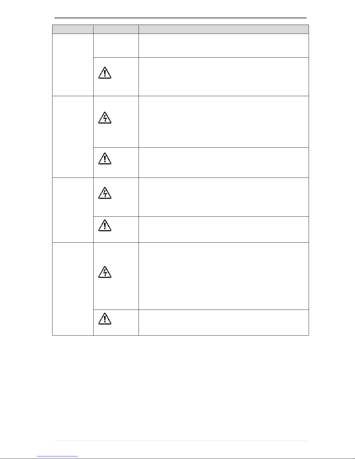
1.1 Safety Precautions
Use stage
Security Level
Precautions
Before
Installation
DANGER
packing water, parts missing or damaged parts, please do not install!
Packaging logo and physical name does not match, please do not
install!
WARNING
Handling should be light lift, otherwise there is the danger of damage
to equipment!
Do not use damaged drive or missing drive. Risk of injury!
Do not touch the control system components by hand, or there is the
danger of electrostatic damage!
During
Installation
DANGER
Please install the flame retardant objects such as metal, away from
combustibles, or may cause a fire!
WARNING
Do not allow lead wires or screws to fall into the drive, otherwise the
drive may be damaged!
Install the drive in a place where there is less vibration and direct
sunlight.
Drive placed in airtight cabinet or confined space, please note the
installation of space to ensure the cooling effect.
Wiring
DANGER
You must follow the guidance of this manual and be used by qualified
electrical engineers. Otherwise, unexpected danger may occur!
There must be a circuit breaker between the drive and the power
supply, otherwise a fire may occur!
Make sure the power supply is in zero-energy state before wiring,
otherwise there is danger of electric shock!
Please follow the standard to the drive properly grounded, otherwise
there is the risk of electric shock!
WARNING
Never connect input power to the drive's output terminals (U, V, W).
Note that the terminal markings, do not take the wrong line! Otherwise
it will cause damage to the drive!
Never connect the braking resistor directly to the DC bus +, - terminals.
Otherwise it will cause a fire!
Refer to the manual's recommendations for the wire diameter used.
Otherwise it may happen accident!
Do not disassemble the connecting cable inside the driver. Otherwise,
the internal of the servo driver may be damaged.
Before
Power-on
DANGER
Make sure the voltage level of the input power is the same as the rated
voltage of the driver. Check if the wiring position of the power input
terminals (R, S, T) and output terminals (U, V, W) is correct; Of the
external circuit is short-circuited, the connection is tightened, or cause
Chapter1 Safety information and precaution VFD500 high performance vector control frequency inverter user manual
- 2 -
Use stage
Security Level
Precautions
damage to the drive!
No part of the drive need to withstand voltage test, the product has
been made before the test. Otherwise it may cause accident!
WARNING
The driver must be covered before the cover can be powered,
otherwise it may cause electric shock!
All peripheral accessories must be wired according to the instructions
in this manual, and be properly wired in accordance with this manual.
Otherwise it may cause accident!
After
Power-on
DANGER
Do not open the cover after power on, otherwise there is danger of
electric shock!
If the indicator light does not light after power on, the keyboard does
not display the situation, immediately disconnect the power switch, do
not touch any input and output terminals of the drive, otherwise there is
the risk of electric shock!
WARNING
If parameter identification is required, preclude the possibility of injury
when rotating the motor!
Do not arbitrarily change the drive manufacturer parameters, or it may
cause damage to the device!
During
Operation
DANGER
Do not touch the cooling fan, radiator and discharge resistance to test
the temperature, otherwise it may cause burns!
Non-professional technicians Do not detect the signal during
operation, otherwise it may cause personal injury or equipment
damage!
WARNING
Drive operation, should avoid something falling into the device,
otherwise it will cause damage to the device!
Do not use the contactor on-off method to control the start and stop the
drive, otherwise it will cause damage to the equipment!
Maintenance
DANGER
Do not live on the equipment repair and maintenance, or there is a risk
of electric shock!
Turn off the input power for 10 minutes before performing maintenance
and repair on the drive, otherwise the residual charge on the capacitor
will cause harm to people!
Do not carry out maintenance and repair on the drive without
personnel who have been professionally trained, otherwise personal
injury or equipment damage will occur!
All pluggable plug-ins must be unplugged in the case of power failure!
The parameters must be set and checked after replacing the drive.
WARNING
Before performing maintenance work on the drive, make sure that the
motor is disconnected from the drive to prevent the motor from feeding
back power to the drive due to accidental rotation.
1.2 Precaution
Contactor using
If the contactor is installed on the power input side of the inverter, do not make the contactor frequent on-off
operation. The interval between ON and OFF of the contactor should not be less than one hour. Frequent
charging and discharging will reduce the use of capacitors in the inverter life.
If a contactor is installed between the inverter output terminals (U, V, W) and the motor, make sure that the
inverter is turned on and off when there is no output. Otherwise, the inverter may be damaged.
Lightning impulse protection
Although this series of inverters are equipped with lightning over-current protection device, there is a certain
degree of self-protection for inductive lightning, but for lightning frequent place, customers should also install
lightning protection device in the front of the inverter.

VFD500 high performance vector control frequency inverter user manual Chapter 1 Safety information and precautions
- 3-
Altitude and derating use
In areas above 1000m above sea level, it is necessary to derate the inverter due to poor air quality due to poor
air quality. In this case, please consult our company.
Power input
The inverter power input should not exceed the operating voltage range specified in this manual. If necessary,
use a step-up or step-down device to change the power supply to the specified voltage range.
Do not change the three-phase inverter to two-phase input, otherwise it will cause malfunction or inverter
damage.
Output filtering
When the cable length between the inverter and the motor exceeds 100 meters, it is suggested to use the
output AC reactor to avoid inverter over-current caused by excessive distributed capacitance. Output filter
according to the needs of the field matching.
Inverter output is PWM wave, please do not install the capacitor on the output side to improve the power factor
or lightning varistor, etc., otherwise it may easily lead to inverter instantaneous overcurrent or even damage the
inverter.
About motor heat and noise
Because the inverter output voltage is PWM wave, contains a certain degree of harmonics, so the motor
temperature rise, noise and vibration compared with the same frequency operation will be slightly increased.
Disposal
Electrolytic capacitors on the main circuit and electrolytic capacitors on the printed circuit board may explode
when incinerated, and poisonous gases are generated when plastic parts are burned. Please dispose as
industrial waste.
The scope of application
This product is not designed and manufactured for use on equipment where life is at stake. To use this product
on a mobile, medical, aerospace, nuclear or other special purpose device, please contact our company For more
information.
This product is manufactured under strict quality control and should be equipped with a safety device if it is
used in a device that may cause a serious accident or damage due to inverter failure.
Chapter 2 Product information VFD500 high performance vector control frequency inverter user manual
- 4 -
Chapter 2 Product Information
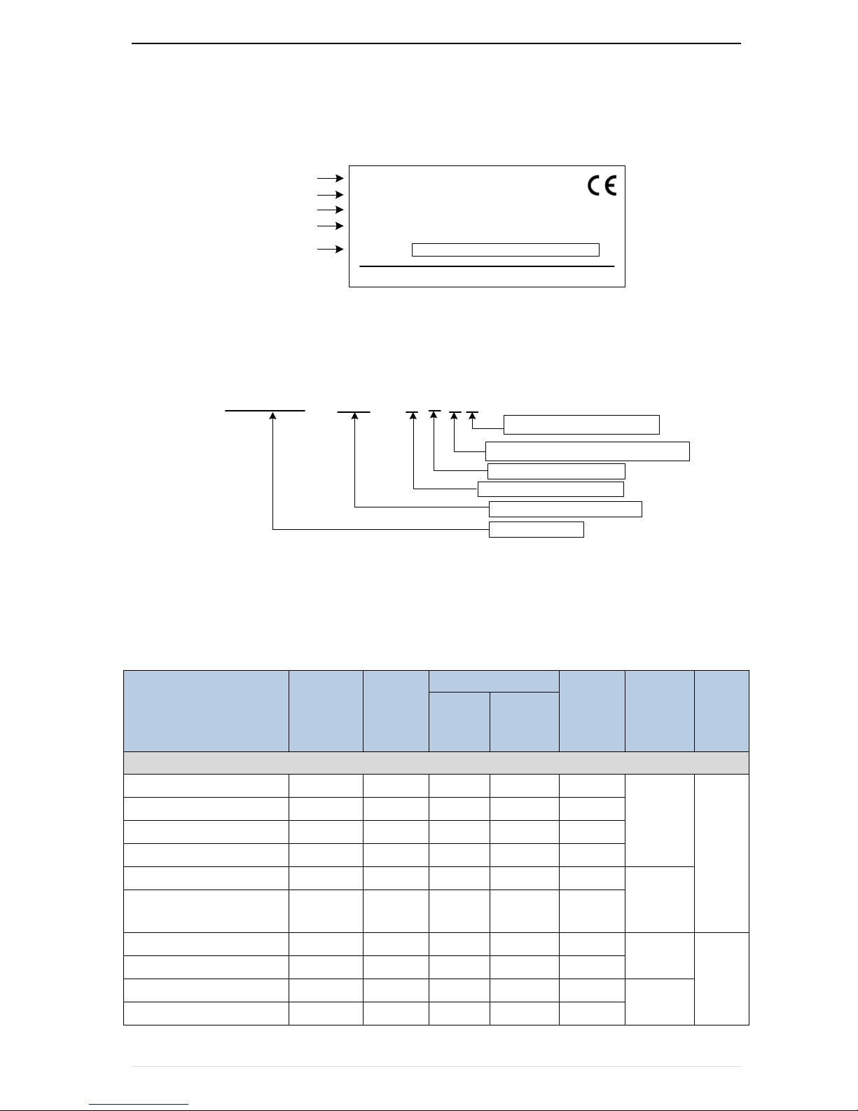
2.1 Designation Rules
Name plate:
MODEL: VFD500-2R2GT4
POWER: 2.2kW/4.0kW
INPUT: 3PH AC380~440V 50Hz/60Hz
OUTPUT: 3PH 0~440V 0~600Hz 5.6A/9.4A
S/N:
TYPE
POWER
INPUT
OUTPUT
CODE
2-1 name plate
Model instruction:
2-2model instruction
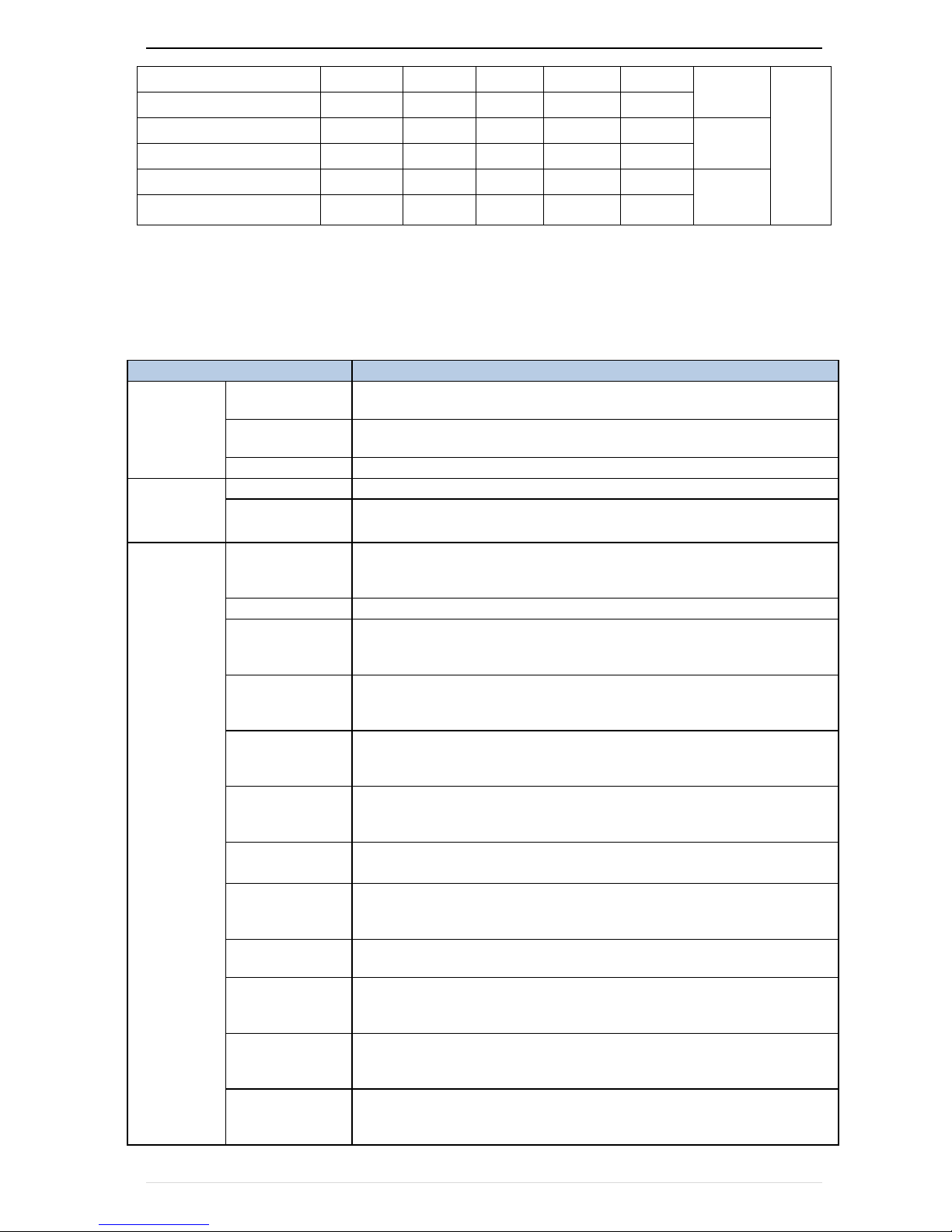
2.2product series instruction
Table 2-1VFD500 inverter models and technical data
Model
Power
capacity
(KVA)
Input
current
(A)
Output current(A)
Adapta
ble
Motor
(KW)
SIZE
Brake
Unit
Heavy
load
Light
load
Three phase: 380-480V,50/60Hz
VFD500-R75GT4B
1.5
3.4
2.5
4.2
0.75
SIZE A
Inter
nal
VFD500-1R5GT4B
3 5 4.2
5.6
1.5
VFD500-2R2GT4B
4
5.8
5.6
9.4
2.2
VFD500-3R7G/5R5PT4B
5.9
10.5
9.4
13.0
3.7
VFD500-5R5G/7R5PT4B
8.9
14.6
13.0
17.0
5.5
SIZE B
VFD500-7R5G/011PT4B
11
20.5
17.0
23.0
7.5
VFD500-011G/015PT4B
17
26.0
25.0
31.0
11
SIZE C
Inter
nal
VFD500-015G/018PT4B
21
35.0
32.0
37.0
15
VFD500-018G/022PT4B
24
38.5
37.0
45.0
18.5
SIZE D
VFD500-022G/030PT4B
30
46.5
45.0
57.0
22
VFD500 -2R2 – G T 4 B
T:three phase
Load type:G normal duty
Power,2R2 means 2.2kW
Product series
B means breaking units
4:380-480v three phase 2: 200-240v
VFD500 high performance vector control frequency inverter user manual Chapter2 production information
- 5-
VFD500-030G/037PT4
40
62.0
60.0
75.0
30
SIZE E
optio
n
VFD500-037G/045PT4
50
76.0
75.0
87.0
37
VFD500-045G/055PT4
60
92.0
90.0
110.0
45
SIZE F
VFD500-055G/075PT4
85
113.0
112.0
135.0
55
VFD500-075G/090PT4
104
157.0
152.0
165.0
75
SIZE G
VFD500-090G/110PT4
112
170.0
176.0
210.0
90
2.3Technical Specifications
Table 2-2 VFD500Technical Specifications
Item
Specifiation
Input
Inuput Voltage
1phase/3phase 220V:200V~240V
3 phase 380V-480V:380V~480V
Allowed Voltage
fluctuation range
-15%~10%
Input frequency
50Hz / 60Hz,fluctuation less than 5%
Output
Output Voltage
3phase:0~input voltage
Overload capacity
General purpose application:60S for 150% of the rated current
Light load application:60S for 120% of the rated current
Control
Control mode
V/f control
Sensorless flux vector control without PG card(SVC)
Sensor speed flux vector control with PG card (VC)
Operating mode
Speed control、Torque control(SVC and VC)
Speed range
1:100 (V/f)
1:200( SVC)
1:1000 (VC)
Speed control
accuracy
±0.5% (V/f)
±0.2% (SVC)
±0.02% (VC)
Speed response
5Hz(V/f)
20Hz(SVC)
50Hz(VC)
frequency range
0.00~600.00Hz(V/f)
0.00~200.00Hz(SVC)
0.00~400.00Hz(VC)
Input frequency
resolution
Digital setting: 0.01 Hz
Analog setting: maximum frequency x 0.1%
Startup torque
150%/0.5Hz(V/f)
180%/0.25Hz(SVC)
200%/0Hz(VC)
Torque control
accuracy
SVC:within 5Hz10%,above 5Hz5%
VC:3.0%
V/f curve
V / f curve type: straight line, multipoint, power function, V / f separation;
Torque boost support: Automatic torque boost (factory setting), manual
torque boost
Frequency giving
ramp
Support linear and S curve acceleration and deceleration;
4 groups of acceleration and deceleration time, setting range 0.00s ~
60000s
DC bus voltage
control
Overvoltage stall control: limit the power generation of the motor by
adjusting the output frequency to avoid skipping the voltage fault;
Chapter 2 Product information VFD500 high performance vector control frequency inverter user manual
- 6 -
Undervoltage stall control: control the power consumption of the motor
by adjusting the output frequency to avoid yaw failure
VdcMax Control: Limit the amount of power generated by the motor by
adjusting the output frequency to avoid over-voltage trip;
VdcMin control: Control the power consumption of the motor by
adjusting the output frequency, to avoid jump undervoltage fault
Carrier frequency
1kHz~12kHz(Varies depending on the type)
Startup method
Direct start (can be superimposed DC brake); speed tracking start
Stop method
Deceleration stop (can be superimposed DC braking); free to stop
Maincontrol
function
Jog control, droop control, up to 16-speed operation, dangerous speed
avoidance, swing frequency operation, acceleration and deceleration
time switching, VF separation, over excitation braking, process PID
control, sleep and wake-up function, built-in simple PLC logic, virtual
Input and output terminals, built-in delay unit, built-in comparison unit
and logic unit, parameter backup and recovery, perfect fault record,fault
reset, two groups of motor parameters free switching, software swap
output wiring, terminals UP / DOWN
function
Keypad
LED Digital keyboard and LCD keypad(option)
communication
Standard:
MODBUS communication
Option:Profibus-DP and CAN OPEN
PG card
Incremental Encoder Interface Card (Differential Output and Open
Collector), Rotary transformer Card
Input terminal
Standard:
5 digital input terminals, one of which supports high-speed pulse input
up to 50kHz;
2 analog input terminals, support 0 ~ 10V voltage input or 0 ~ 20mA
current input;
Option card:
4 digital input terminals
2 analog input terminals.support-10V-+10V voltage input
Output terminal
standard:
1 digital output terminal;
1 high-speed pulse output terminal (open collector type), support 0 ~
50kHz square wave signal output;
1 relay output terminal(second relay is an option )
2 analog output terminals, support 0 ~ 20mA current output or 0 ~ 10V
voltage output;
Option card: 4 digital output terminals
Protection
Refer to Chapter 6 "Troubleshooting and Countermeasures" for the protection function
Environment
Installation
location
Indoor, no direct sunlight, dust, corrosive gas, combustible gas, oil
smoke, vapor, drip or salt.
Altitude
0-3000m.inverter will be derated if altitude higher than1000m and
rated output current will reduce by 1% if altitude increase by 100m
Ambient
temperature
-10°C~ +40°C,maximum 50°C (derated if the ambient temperature is
between 40°C and 50°C)Rated output current decrease by 1.5% if
temperature increase by 1°C
Humidity
Less than 95%RH, without condensing
Vibration
Less than 5.9 m/s2 (0.6 g)
Storage
temperature
-20°C ~ +60°C
others
Installation
Wall-mounted, floor-controlled cabinet, transmural
Protection level
IP20
cooling method
Forced air cooling
VFD500 high performance vector control frequency inverter user manual Chapter3 Product appearance and wiring
- 7-
Chapter 3 Product appearance and Installation Dimension
3.1 Product appearance and installation
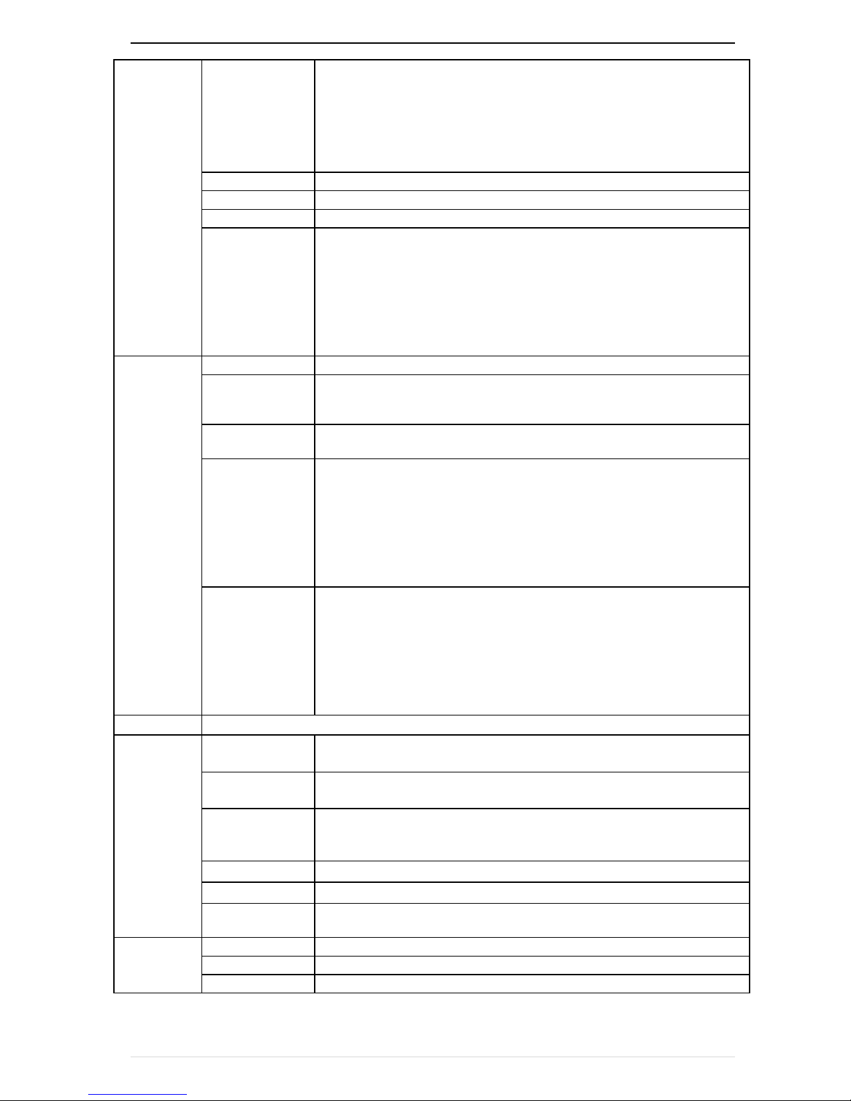
3.1.1Product appearance
fan
Name plate
cover
Line board
Keypad
Fan cover
Back cover
Front cover
Main circuit terminal
Extension card port
Control terminal
3-1:VFD500 series appearance
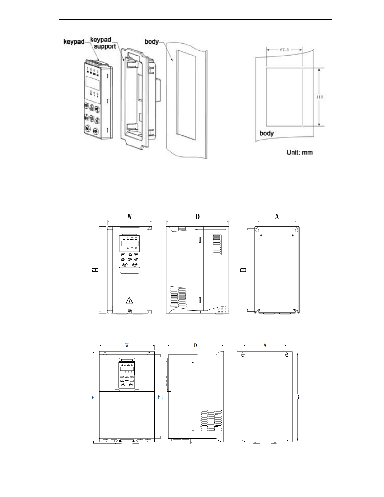
3.1.2Appearance and Mounting Hole Dimension
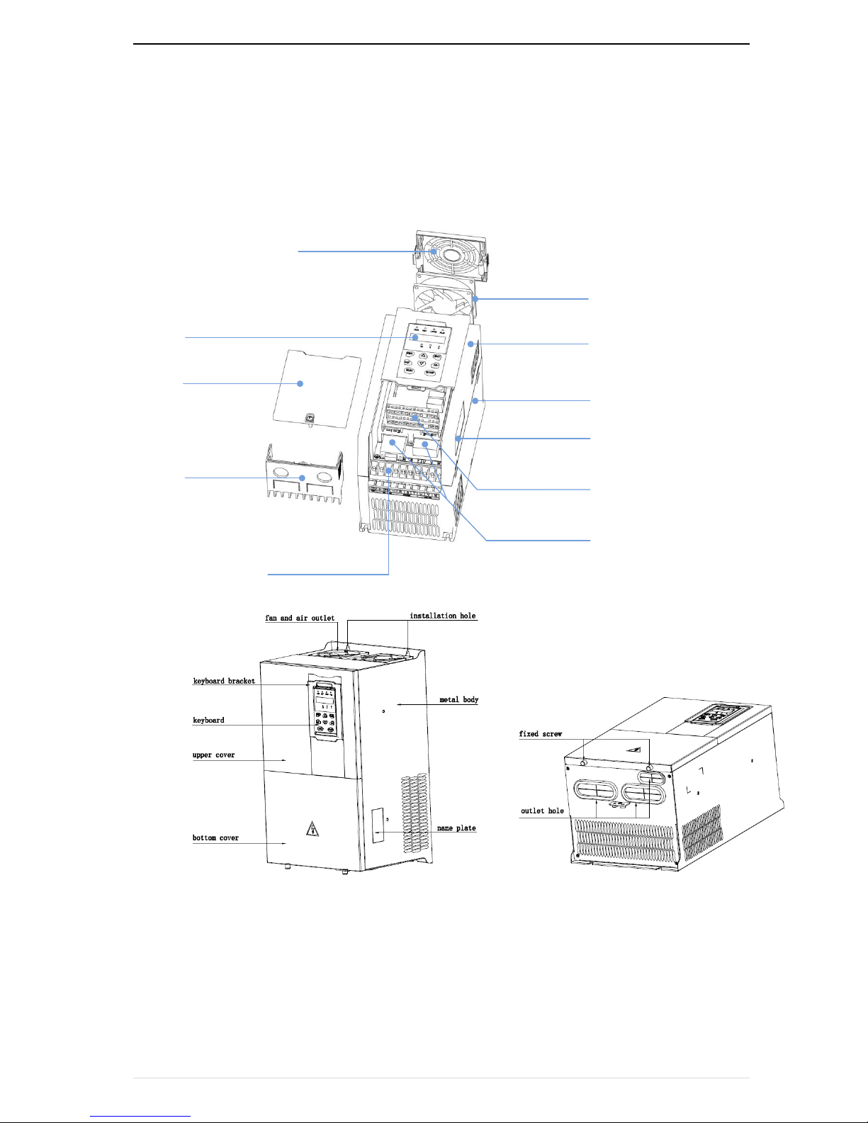
Keypay and keypad support size
The dimensions of the VFD500 series keypad are shown in Figure 3-1. When installing the keypad on the outside of
the control cabinet, use the two screws on the back of the keypad to fix it (right side of Figure 3-1).
Chapter3 product appearance and wiring VFD500 high performance vector control frequency inverter user manual
- 8 -
diagram 3-2keypad dimension
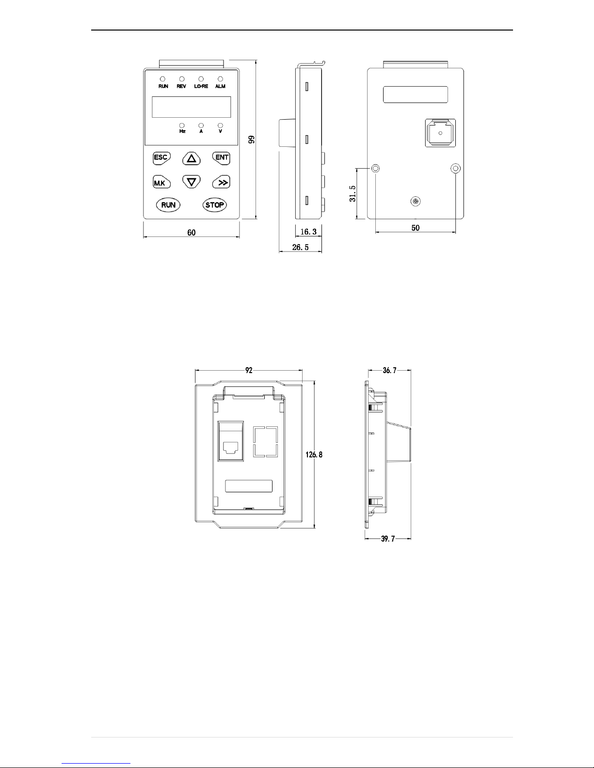
If you want to install the keypad on the inside of the control cabinet (to prevent the keypad from protruding toward
the outside of the control cabinet), use a keypad Bracket. The dimensions of the keypadbracket are shown in Figure
3-2. The dimensions of the installation diagram and control cabinet are shown in Figure 3-3.
M3 screw X2 depth 8mm (for
mounting to the control cabinet)
Figure 3-3 Keypad Holder Size (Unit: mm)
VFD500 high performance vector control frequency inverter user manual Chapter3 Product appearance and wiring
- 9-
Figure 3-4 Keypad support installation diagram and control cabinet processing dimensions
Inverter dimensions and installation dimensions
Figure 3-5 SIZE A to SIZE C Dimensions
Figure 3-6 SIZE D~G Dimensions
Chapter3 product appearance and wiring VFD500 high performance vector control frequency inverter user manual
- 10 -
Table 3-1 VFD500 series appearance and installation dimension
SIZE
Appearance and installation dimension(mm)
A B H
H1 W D
Φd
Mounting
screws
SIZE A
87
206.5
215 / 100
170
ø5.0
M4X16
SIZE B
114
239.5
250 / 130
180
ø5.0
M4X16
SIZE C
159
298
310 / 180
193
Ø6.0
M5X20
SIZE D
165
350
365 210
205
Ø6.0
M5X20
SIZE E
170
437
452.5 260
230
Ø7.0
M6X16
SIZE F
250
535
555 310
275
Ø10.0
M8X20
SIZE G
280
620
640 350
290
Ø10.0
M8X20
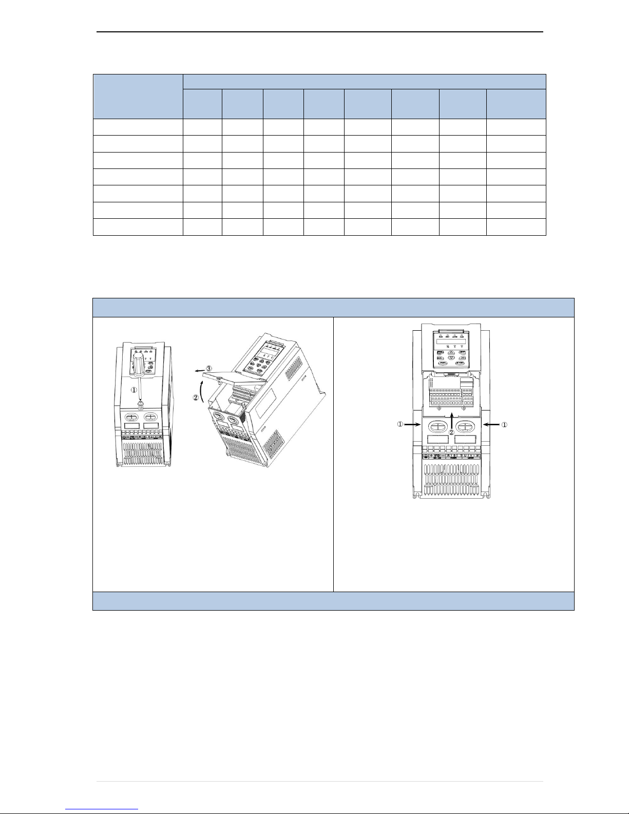
3.1.3Removal and installation of cover and inlet plate
SIZEA~SIZE CRemoval and installation of cover and inlet plate:
Removal steps
Step 1: Open the top cover
① Unscrew the screw on the cover
② Lift up the cover
③ Remove the cover from the front
Step 2: Take out the inlet board
① Hold down the sides of the inlet plate with your
thumb and middle finger
② Press to disengage the buckle and pull it out of the
board
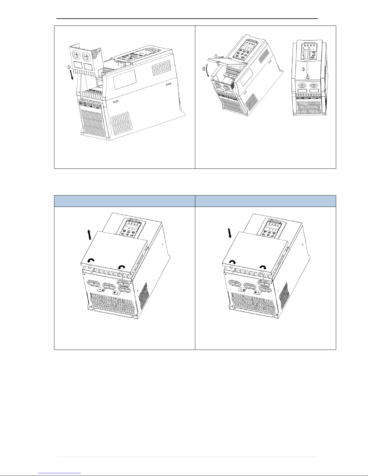
installation steps
VFD500 high performance vector control frequency inverter user manual Chapter3 Product appearance and wiring
- 11-
① Step 1: Install the inlet board
② Put the inlet board from the top down into the
mounting position to ensure that the card buckles
Step 2: Install the upper cover
① Slant the front cover diagonally from the front to
the docking station
② Lower the cover plate toward the inlet board
③ Tighten the screws on the cover
SIZEDRemoval and installation of cover and inlet plate:
Removal steps
installation steps
① Unscrew the two screws at the bottom of the
bottom cover
② Remove the cover vertically
① Close the cover vertically
② Tighten the two screws on the bottom of the cover
○2
○1
○1
○2
○2
○1
Chapter3 product appearance and wiring VFD500 high performance vector control frequency inverter user manual
- 12 -
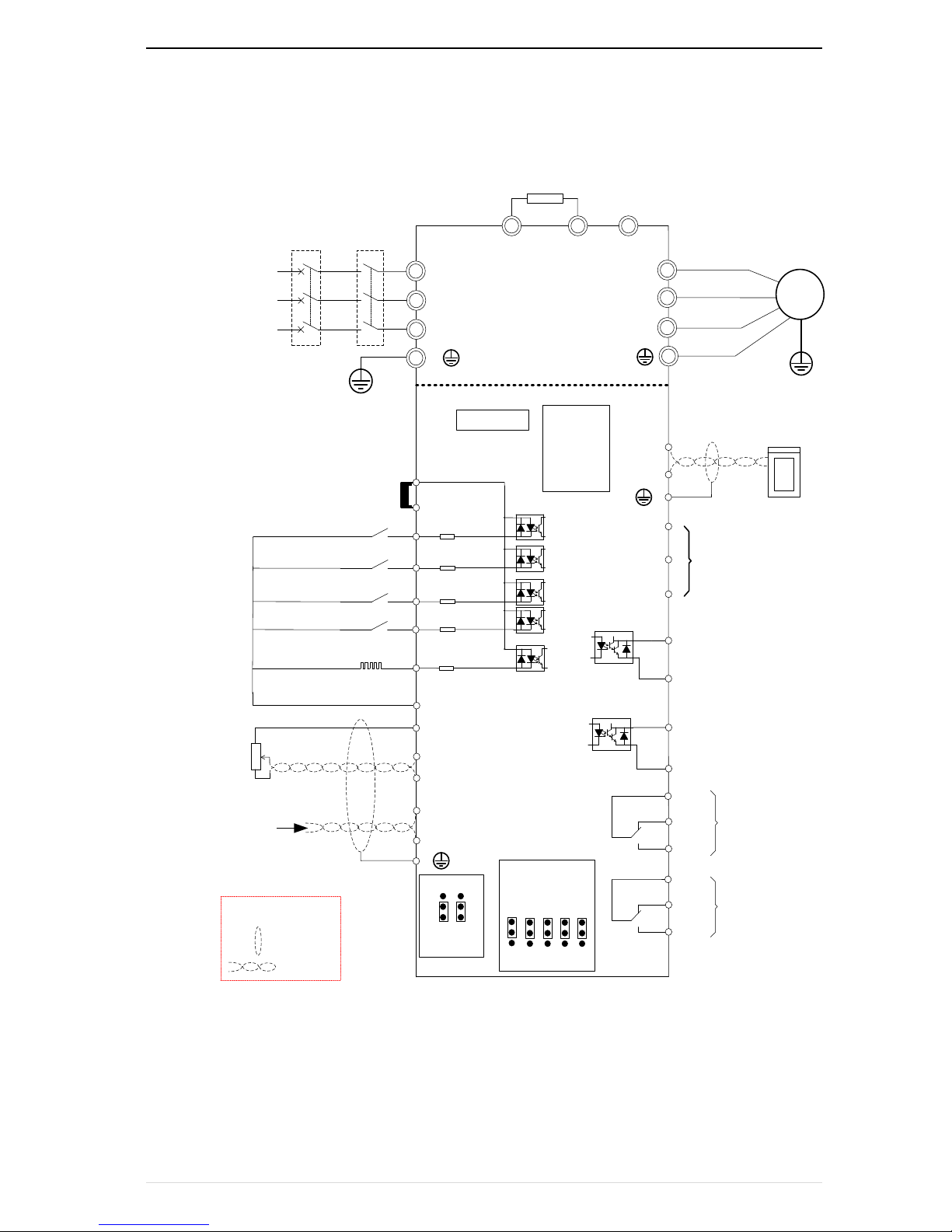
3.2Wiring
3.2.1 Standard wiring diagram
Break resistance
M
U
V
W
R/L1
S/L2
T/L3
3 phase AC input
DI1
DI2
DI3
DI4
COM
AI1
AI2
GND
485+
485-
RS485 port
AO2
GND
AO1、AO2 output:
0~10V/0~20mA
DO
1
CO
M
T1A
T1C
T1B
Relay
output 2
Digital input 1
Digital input 2
Digital input 3
Digital input 4
+10V
Open collector
output1
PLC
+24V
FWD
REV
-
+
PB
HDI
High speed
pluse
terminal
HD
O
COM
Open collector
output2
High speed pluse
output
IO
communi
cation
extension
card
PG card
AO1
380V~ 50/60Hz
Analog input
0~10V/0~20m
A
1~5k
T2A
T2B
T2C
Relay
output 1
485
OFF
ON
AI1VAI2
V
I I I I
AO
1
V
AO
2
V
ON ON
OFF OFF
Ground
Connector slip
GND
Twisted
cable
shield
Note
:
breaker
contactor
Main circuit
Control circuit
PE1
PE2
PC
Diagram 3-7standard wiring
VFD500 high performance vector control frequency inverter user manual Chapter3 Product appearance and wiring
- 13-
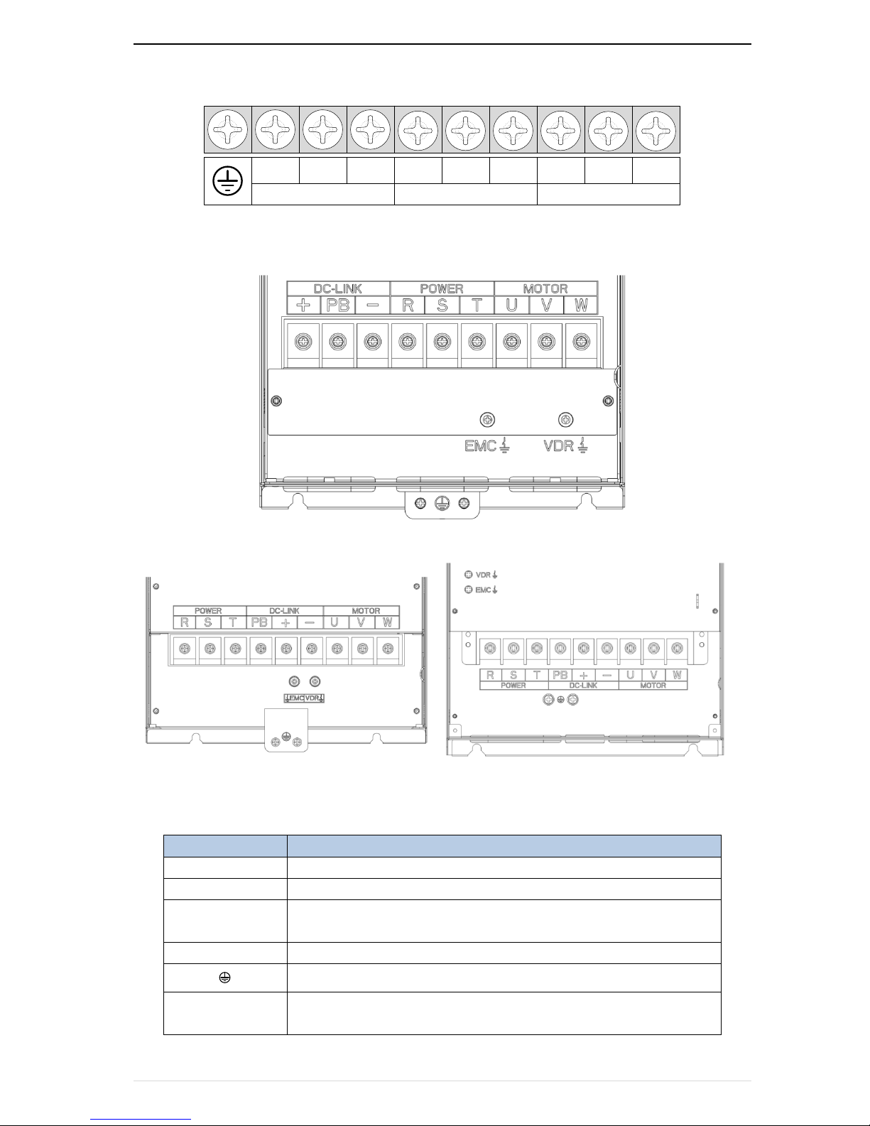
3.2.2Main Circuit Terminals
+ PB -
DC-LINK
R S T
POWER
MOTOR
U V W
Figure 3-8 SIZE A~SIZE C Main Circuit Terminal
Figure 3-9 SIZE D main circuit terminal block diagram
Figure 3-10 SIZE E(LEFT) SIZE F~G(RIGHT) Main Circuit Terminal Blocks
Table 3-2 Function description of the main circuit terminal of the inverter
Terminal
Function instruction
R、S、T
AC power input terminal, connect three-phase AC power
U、V、W
Inverter AC output terminal, connect three-phase AC motor
+、-
The positive and negative terminals of the internal DC bus are connected to the
external brake unit or For common DC bus
+、PB
Braking resistor connection terminal when built-in brake unit
Ground terminal, ground
EMC、VDR
Safety capacitor and varistor grounding selection screw (SIZE A~SIZE C EMC
screw on the left side of the fuselage)

Chapter3 product appearance and wiring VFD500 high performance vector control frequency inverter user manual
- 14 -
3.2.3 Terminal screws and wiring specifications
Table 3-3 Main circuit cable and screw specifications
Model number
Power terminal
Ground terminal
Screw
Tightening
torque(Nm)
Cable
diameter
(mm2)
screw
Tightening
torque(Nm)
Cable
diameter
(mm2)
VFD500-R75GT4B
M3
1.5
2.5
M3
1.5
2.5
VFD500-1R5GT4B
M3
1.5
2.5
M3
1.5
2.5
VFD500-2R2GT4B
M3
1.5
2.5
M3
1.5
2.5
VFD500-3R7G/5R5PT4B
M3
1.5
4
M3
1.5
4
VFD500-5R5G/7R5PT4B
M4 2 6
M4 2 6
VFD500-7R5G/011PT4B
M4 2 6
M4 2 6
VFD500-011G/015PT4B
M5 4 10
M5 4 10
VFD500-015G/018PT4B
M5 4 10
M5 4 10
VFD500-018G/022PT4B
M6 4 10
M6 4 10
VFD500-022G/030PT4B
M6 4 16
M6 4 16
VFD500-030G/037PT4
M8
10
16
M6 5 10
VFD500-037G/045PT4
M8
10
16
M6 5 10
VFD500-045G/055PT4
M8
10
35
M8 8 16
VFD500-055G/075PT4
M8
10
50
M8 8 25
VFD500-075G/090PT4
M10
20
70
M10
20
35
3.2.4 Cautions for Main Circuit Wiring
(1)Power Supply Wiring
◆ It is forbidden to connect the power cable to the output terminal of the inverter. Otherwise, the internal
components of the inverter will be damaged.
◆ In order to provide input side overcurrent protection and power outage overhaul convenience, the inverter should
be connected to the power supply through circuit breakers and contactors.
◆ Please confirm the power phase, the voltage is consistent with the product nameplate, do not match may result
in damage to the inverter.
(2)DC wiring
◆ Do not connect the braking resistor directly to +, -, which may cause the inverter to be damaged or
even fire.
◆ When using the external brake unit, pay attention to +, - can not be reversed, otherwise it will cause
damage to the inverter and brake unit or even cause a fire.
(3)Motor Wiring
◆It is forbidden to short circuit or ground the inverter output terminal, otherwise the internal components
of the inverter will be damaged.
VFD500 high performance vector control frequency inverter user manual Chapter3 Product appearance and wiring
- 15-
◆Avoid short circuit the output cables or with the inverter enclosure, otherwise there exists the danger of
electric shock.
◆It is forbidden to connect the output terminal of the inverter to the capacitor or LC/RC noise filter with
phase lead, otherwise, the internal components of the inverter may be damaged.
◆When contactor is installed between the inverter and the motor, it is forbidden to switch on/off the
contactor during the running of the inverter, otherwise, there will be large current flowing into the
inverter, triggering the inverter protection action.
◆Length of cable between the inverter and motor
If the cable between the inverter and the motor is too long, the higher harmonic leakage current of the
output end will produce by adverse impact on the inverter and the peripheral devices. It is suggested
that when the motor cable is longer than 100m, output AC reactor be installed. Refer to the following
table for the carrier frequency setting.
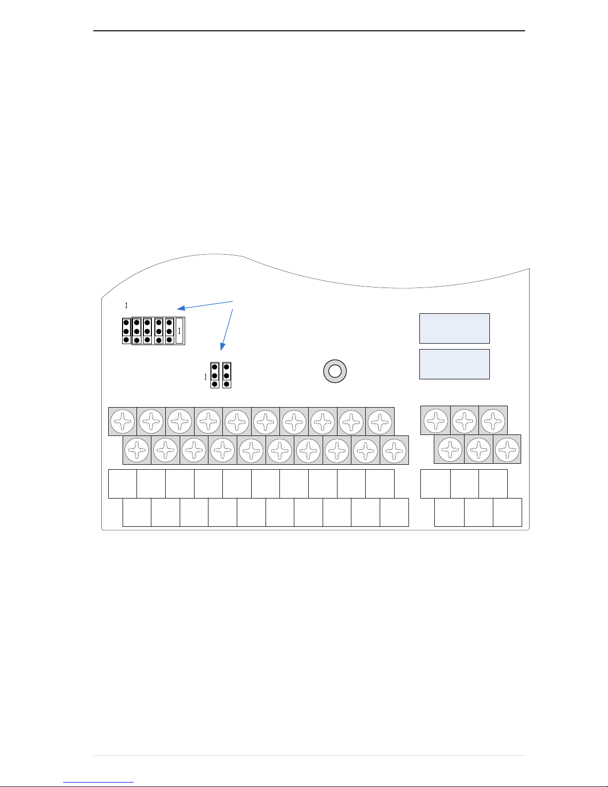
3.2.4Control Circuit Terminal
+10V
AI1
AO1
485+ GND
DI1 DI2
DI3
DI4
HDI
GND
AI2 AO2
485- COM
DO1 HDO
COM PLC +24V
T1/A
T1/B
T1/C
T2/A T2/B T2/C
485
V
I
ON OFF
AI1 AI2 AO1 AO2
ON OFF
PE1 PE2
K2
K1
Jumper switch
Diagram 3-11 VFD500 control circuit terminal

Chapter3 product appearance and wiring VFD500 high performance vector control frequency inverter user manual
- 16 -
Table 3-3VFD500 control circuit terminal instruction
Type
Terminal
Symbol
Terminal
Name
Terminal function description
Analog
input
voltage
+10V
Input voltage
10.10V±1%
Maximum output current:10mA,it provides power
supply to external potentiometer with resistance range
of:1KΩ~51KΩ
GND
Ananog
ground
Internal isolation from COM
AI1
Analog
input1
Input voltage:0~10V:Impedance 22KΩ,Maximum
input voltage
Input current:0~20mA:Impedance 500Ω,Maximum
input current
Through the jumper switch AI1 0 ~ 10V and 0 ~ 20mA
analog input switch, the factory default voltage input.
AI2
Analog input
2
Input voltage:0~10V:Impedance 22KΩ,Maximum
input voltage
Input current:0~20mA:Impedance 500Ω,Maximum
input current
Through the jumper switch AI1 0 ~ 10V and 0 ~ 20mA
analog input switch, the factory default voltage input.
Analog
input
AO1
Analog
output 1
Output voltage:0~10V:Impedance ≥10KΩ
Output current:0~20mA:Impedance 200Ω~500Ω
Through the jumper switch AO1 0 ~ 10V and 0 ~ 20mA
analog output switching, the factory default voltage
output.
AO2
Analog
output 2
Output voltage:0~10V:Impedance ≥10KΩ
Output current:0~20mA:Impedance 200Ω~500Ω
Through the jumper switch AO1 0 ~ 10V and 0 ~ 20mA
analog output switching, the factory default voltage
output.
GND
Ananog
ground
Internal isolation from COM
Switch
input
+24V
+24V current
24V±10%,Internal isolation from GND
Maximum output current:200mA
To provide 24V power supply, generally used as a
digital input and output terminal power supply and
external sensor power
PLC
Digital input
terminal
common
The factory default setting is connected PLC with
+24V
Terminal for on-off input high and low level switch
When using the external signal to drive DI1~DI5, it
will disconnect the connector slip of PLC with the +24V
COM
+24V ground
Internal isolation from GND
DI1~DI4
Digital input
terminal 1~4
Optocoupler isolation, compatible with bipolar input
Frequency range:0~200Hz
Voltage range:10V~30V
HDI
Digital input
Digital input terminal:same as DI1~DI4
VFD500 high performance vector control frequency inverter user manual Chapter3 Product appearance and wiring
- 17-
Type
Terminal
Symbol
Terminal
Name
Terminal function description
terminal
/High-speed
pulse input
Pulse input frequency input:0~50KHz
Voltage range:10V~30V
Switch
output
DO1
Open
collector
output
Optocoupler isolation
Voltage range:0V~24V
Current range:0mA ~50mA
HDO
Open
collector
output
/High-speed
pulse output
Open collector output:same as DO1
High-speed pulse output:0~50KHz
Relay
output 1
TA/TB/TC
Relay output
T1A-T1B:nomal open
T1A-T1C:nomal close
Contact rating:AC 250V,3A;DC 30V,1A
Relay
output2
(optional)
T2A/T2BT2C
Relay output
T2A-T2B:nomal open
T2A-T2C:nomal close
Contact rating:AC 250V,3A;DC 30V,1A
485 port
485+
485 Positive
differential
signal
Baud rate:
1200/2400/4800/9600/19200/38400/57600/115200bps
485-
485 Negative
differential
signal
Table 3-5 Functional Description of VFD500 Jumper Switch
Name
Function
Defaults
485
485 Termination resistor selection: ON has 100 ohm
terminating resistor, OFF is no terminating resistor
OFF
AI1
AI1 analog type selection: V is the voltage input (0 ~ 10V), I is
the current input (0 ~ 20mA)
V
AI2
AI2 analog type selection: V is the voltage input (0 ~ 10V), I is
the current input (0 ~ 20mA)
V
AO1
AO1 analog type selection: V is the voltage output (0 ~ 10V), I
is the current output (0 ~ 20mA)
V
AO2
AO2 analog type selection: V is the voltage output (0 ~ 10V), I
is the current output (0 ~ 20mA)
V
PE1
GND ground selection: ON is grounded through the safety
capacitor, OFF is not connected
OFF
PE2
COM ground selection: ON is grounded through the safety
capacitor, OFF is not connected
OFF
Analog input terminal instructions
The AI1 and AI2 terminals can accept both analog voltage input and analog current input. They can
be switched by jumpers “AI1” and “AI2” on the IO board. The connection method and jumper switch
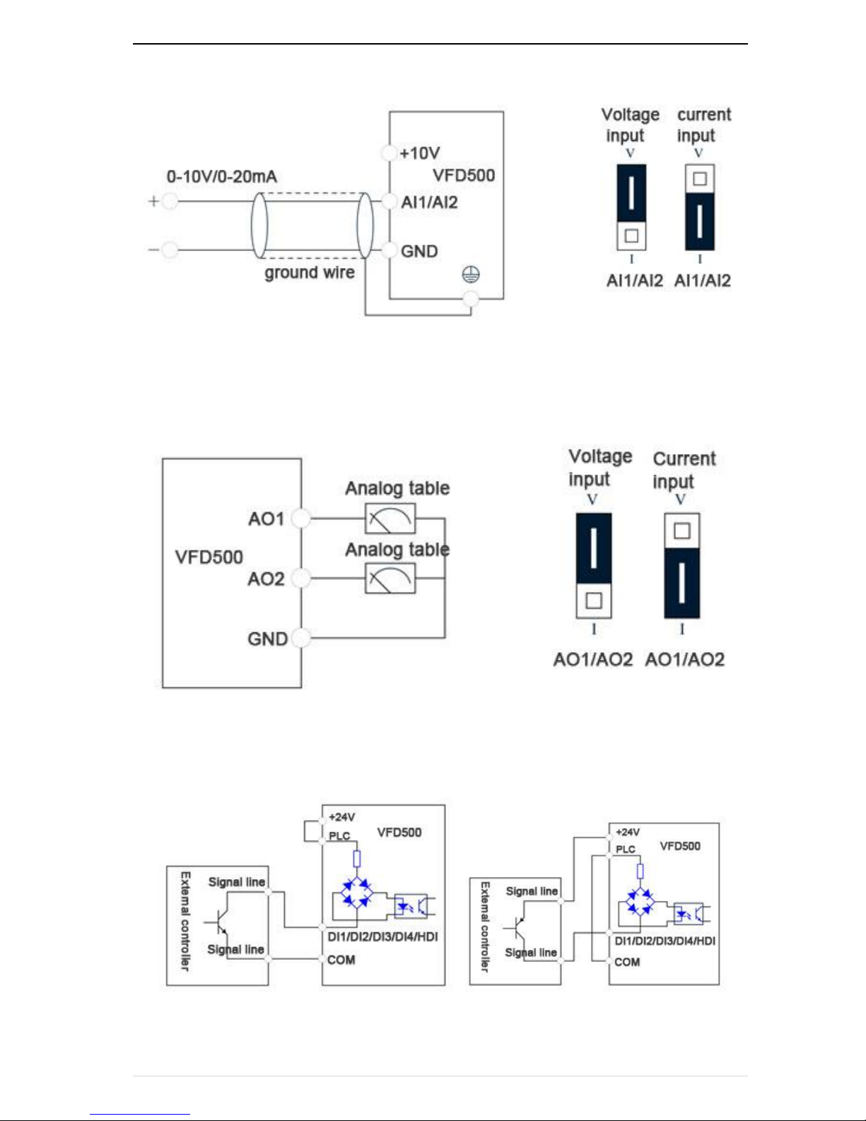
Chapter3 product appearance and wiring VFD500 high performance vector control frequency inverter user manual
- 18 -
configuration are shown in the following figure:
Figure 3-11 Analog input terminal wiring diagram
The AO1 and AO2 terminals support the voltage output (0~10V) and the current output (0~20mA). They are selected
by jumpers “AO1” and “AO2” on the IO board. The connection method is as shown in the figure below:
Figure 3-12 Analog output terminal wiring diagram
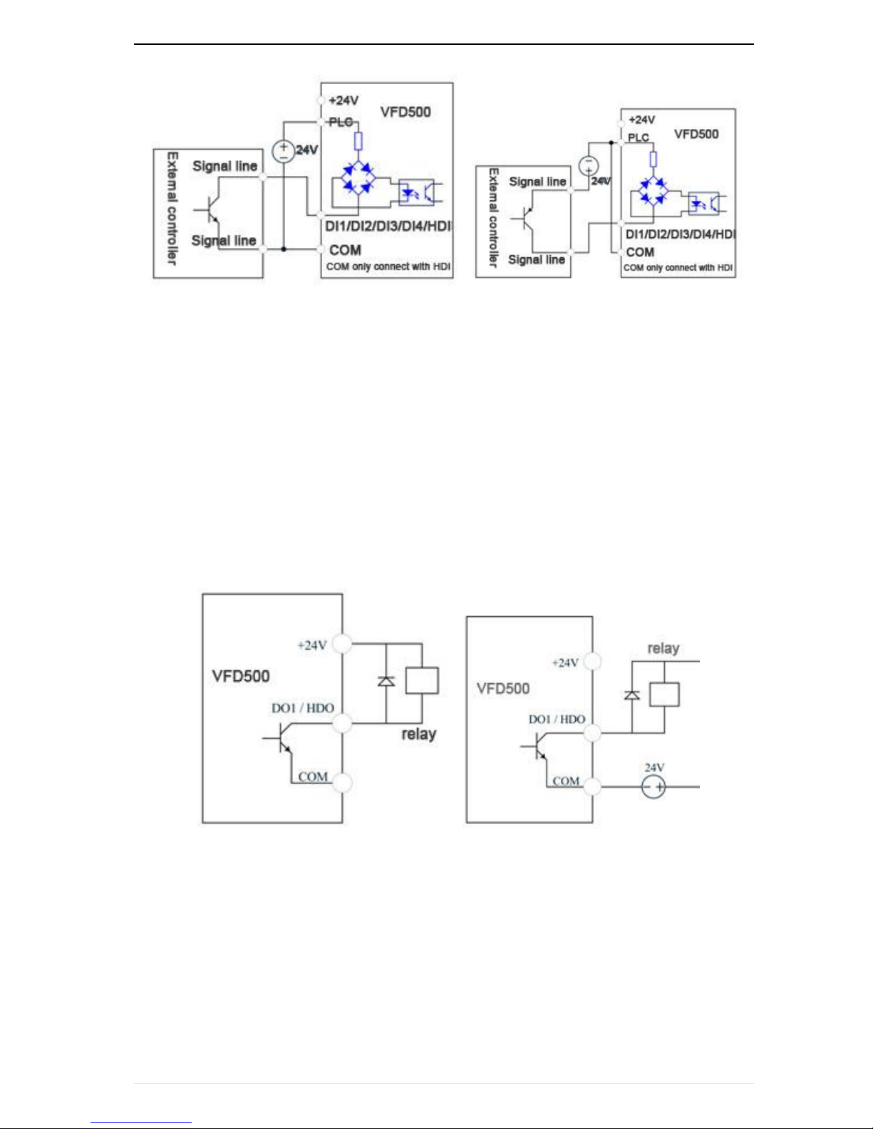
Digital input terminal instructions
A:By internal 24V with NPN modeB:By internal 24V with PNP mode
VFD500 high performance vector control frequency inverter user manual Chapter3 Product appearance and wiring
- 19-
C:NPN mode uses external +24V power supplyD:PNPNPN mode uses external +24V power supply
3-13 Switching Digital input terminal wiring diagram
Note:
When using an external power supply, the shorting tab between +24V and PLC must be removed, otherwise the
product will be damaged!
When using an external power supply, connect the negative terminal of the external power supply to COM when
using HDI, otherwise HDI is invalid!
Switch output terminal instructions
The multi-function output terminals DO1 and HDO can be powered by the internal +24V power supply of the inverter
or an external power supply. The wiring diagram is as follows:
A、Use internal power supply B、Use external power supply
3-14 Switchingdigital output terminal wiring diagram
Note:
The multi-function terminal output is an open collector output with a maximum allowable current of 50mA. When
using the internal power supply, if the inductive load is driven, an absorption circuit such as an RC snubber circuit or
a freewheeling diode should be installed. When adding a freewheeling diode, be sure to confirm the polarity of the
diode, otherwise the product will be damaged. For external power supply, connect the negative terminal of the
Chapter3 product appearance and wiring VFD500 high performance vector control frequency inverter user manual
- 20 -
external power supply to the COM terminal.
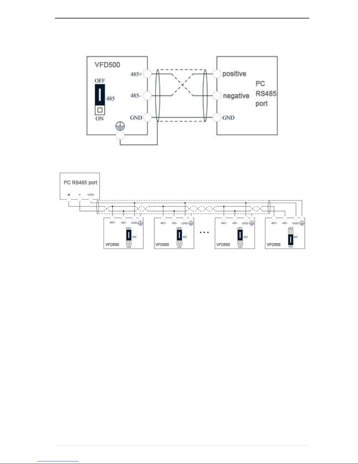
485Communication terminal instructions
3-15Single inverter RS485 directly communicates with the host computer
3-16Multiple inverter RS485 is connected to the host computer for communication

VFD500 high performance vector control frequency inverter user manual Chapter3 Product appearance and wiring
- 21-
3.3EMCquestion and solution
The working principle of the inverter determines that it will certainly produce electromagnetic interference,
affecting and interfering with other equipment. In the meantime, the frequency converter usually works under the
industrial environment with very strong noise,its internal weak signal is also easily disturbed. For safe and
trouble-free operation of the frequency converter, as well as the normal and orderly operation of other equipment,
install the equipment according to the following rules.。
Install the input noise filter,the filter to the inverter input power supply side of the wiring should be as short
as possible.
Filter shell and the installation of the cabinet should be a large area of reliable connection, in order to
reduce the noise current loop impedance.
The wiring distance between inverter and motor should be as short as possible. The motor cable adopts
4-core cable. One end of the ground wire is grounded at the inverter side and the other end is connected
with the motor case. The motor cable is sheathed into the metal pipe.
Input power line and output motor line should be far away from each other.
Easily affected equipment and signal lines should be installed away from the inverter.
The key signal cable should use shielded cable. It is suggested that the shielded cable layer should be
grounded by 360 degree grounding method and set in the metal pipe. As far as possible from the inverter
input power cable and output motor cable, if the signal cable must cross the input power cable or output
motor cable, the two should be orthogonal.
When using the analog voltage and current signals for remote frequency setting, double-stranded,
shielded and shielded cables should be used, and the shield should be connected to the grounding
terminal PE of the inverter. The longest signal cable should not exceed 50 meters.
The control circuit terminals T1A / T1B / T1C, T2A / T2B / T2C and other control circuit terminals should be
separated wiring.
It is forbidden to short-circuit the shield with other signal lines and equipment.
When connecting the inductive load device (magnetic contactor, relay, solenoid valve, etc.) to the inverter,
be sure to use the surge suppressor on the load device coil.
Correct and reliable grounding is safe and reliable operation of the foundation:
(1) Inverter will generate leakage current, the greater the carrier frequency, the greater the leakage current.
Inverter leakage current greater than 3.5mA, the size of the leakage current by the conditions of use, in order to
ensure safety, inverter and motor must be grounded;
(2) Grounding resistance should be less than 10 ohms. Grounding cable diameter requirement, refer to the
same type of input and output cables half of the cross-sectional area selection;
(3) Do not share the ground wire with welding machines and other power equipment;
(4) When using more than two inverters, do not make the ground wire loop.。
Inverter1 inverter2 inverter3
Invert1 Inverter2 inverter3
Correctincorrect
3-6Ground wire connection diagram
Frequency converter to motor cable length and carrier frequency to maintain the appropriate
relationship
When the cable between the inverter and the motor is long, due to the influence of distributed capacitance, it is easy
to produce electrical resonance, thus generating a large current so that the inverter over-current protection. It is

Chapter3 product appearance and wiring VFD500 high performance vector control frequency inverter user manual
- 22 -
recommended to install the AC output reactor when the motor cable length exceeds 100 meters. Refer to the
following table for carrier frequency setting
.3-3 Inverter output cable length and carrier frequency table
Cable length between drive
and motor
20m below
50m below
100m below
100m above
Carrier frequency(P22.00)
15kHz below
8kHz below
4kHz below
2kHzbelow
Chapter 4 Operation and display VFD500 high performance vector control frequency inverter user manual
- 23-
Chapter 4 Operation and display
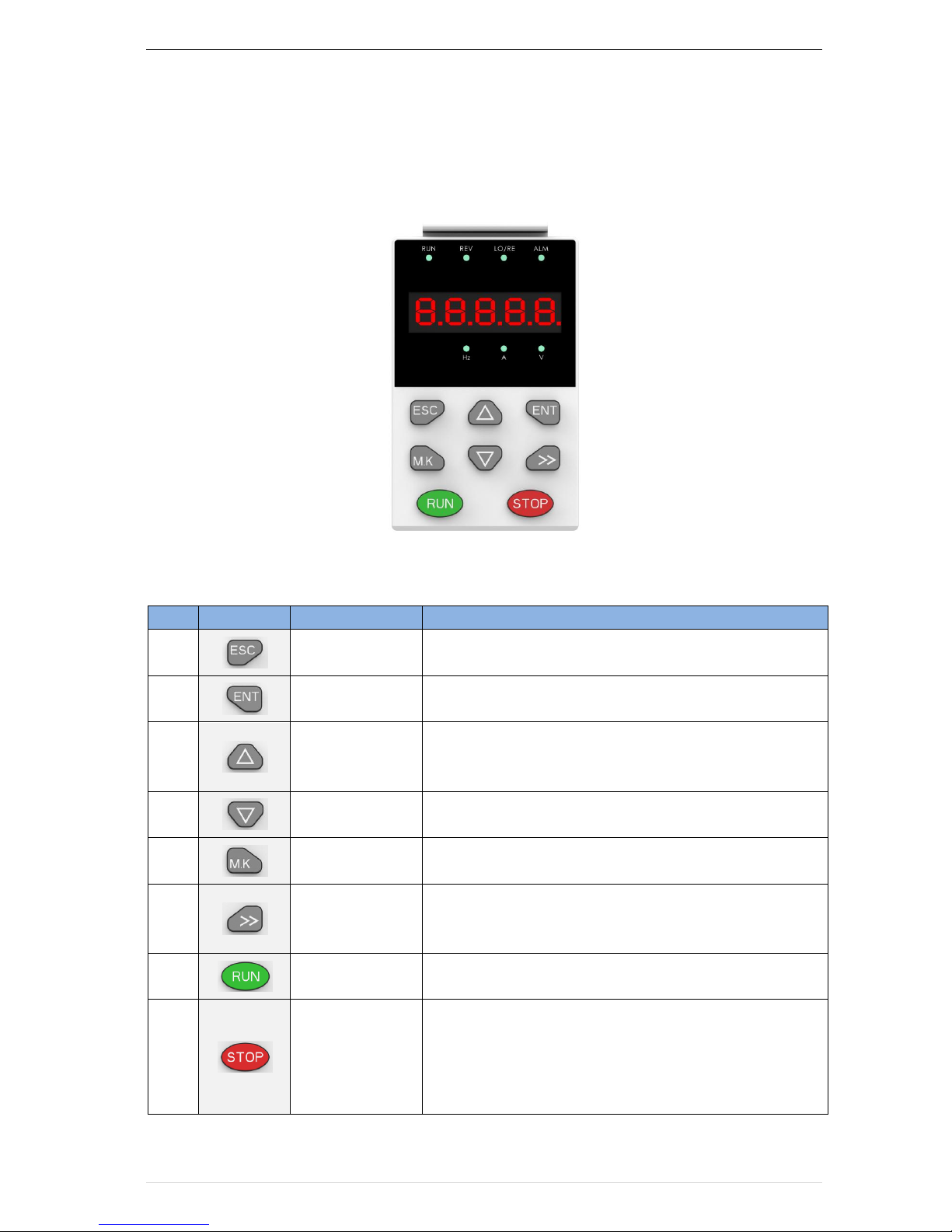
4.1 LED Instruction of operation and display
LED keyboard consists of 5 digital tubes, 7 lights, 8 keys and a potentiometer; can be used to set
the parameters, status monitoring and operation control, LED keyboard shape as shown in Figure 4-1:
Figure 4-1 Operating panel
Description of indicator
Table 4-1 The name and function of each part of the keyboard
No.
Part
Name
Function
1 Exit
•
exit menu level
2 Confirmation
•
Enter the menu interfaces level by level,
•
confirm the parameter setting and save to EEPROM
3 Increment
• The number indicated by the cursor increases by one.
• Next function code.
• Used to switch the left and right screens while in monitor mode
4 Decrement
·The number indicated by the cursor minus one.
• The previous function code.
5
Multi-function
·
Perform function switchover according to the setting of
21.02
6 Shift
• Cursor shift.
• Monitor Status Displays the next monitor volume.
• Switch left and right screens.
7 Run
Start the frequency inverter in the operation panel control
mode
8 Stop/Reset
• During operation, press to stop the operation (restricted by
parameter 21.03).
• In fault status, press this key to reset the fault.
VFD500 high performance vector control frequency inverter user manual Chapter 4 Operation and display
- 24 -
9 Indicator light:Hz
·Indicate the digital display unit, all three lights off menas other
units
10 Indicator light:A
11 Indicator light:V
12 Running lights
• Off: indicates a stop condition.
• On: indicates inverter is running.·
Blinking: Deceleration stopped.
13 Direction indicator
• Used to indicate the sign of the variable when the LED is
displaying one of the variables listed in 27.02;
• In other cases the sign of the output frequency is indicated.
14
Command source
indicator
• Off: The command source is the keyboard.
• On: The command source is terminal.
• Blinking: The command source is communication.
15 Fault indicator
• When it is on, the drive is faulty.
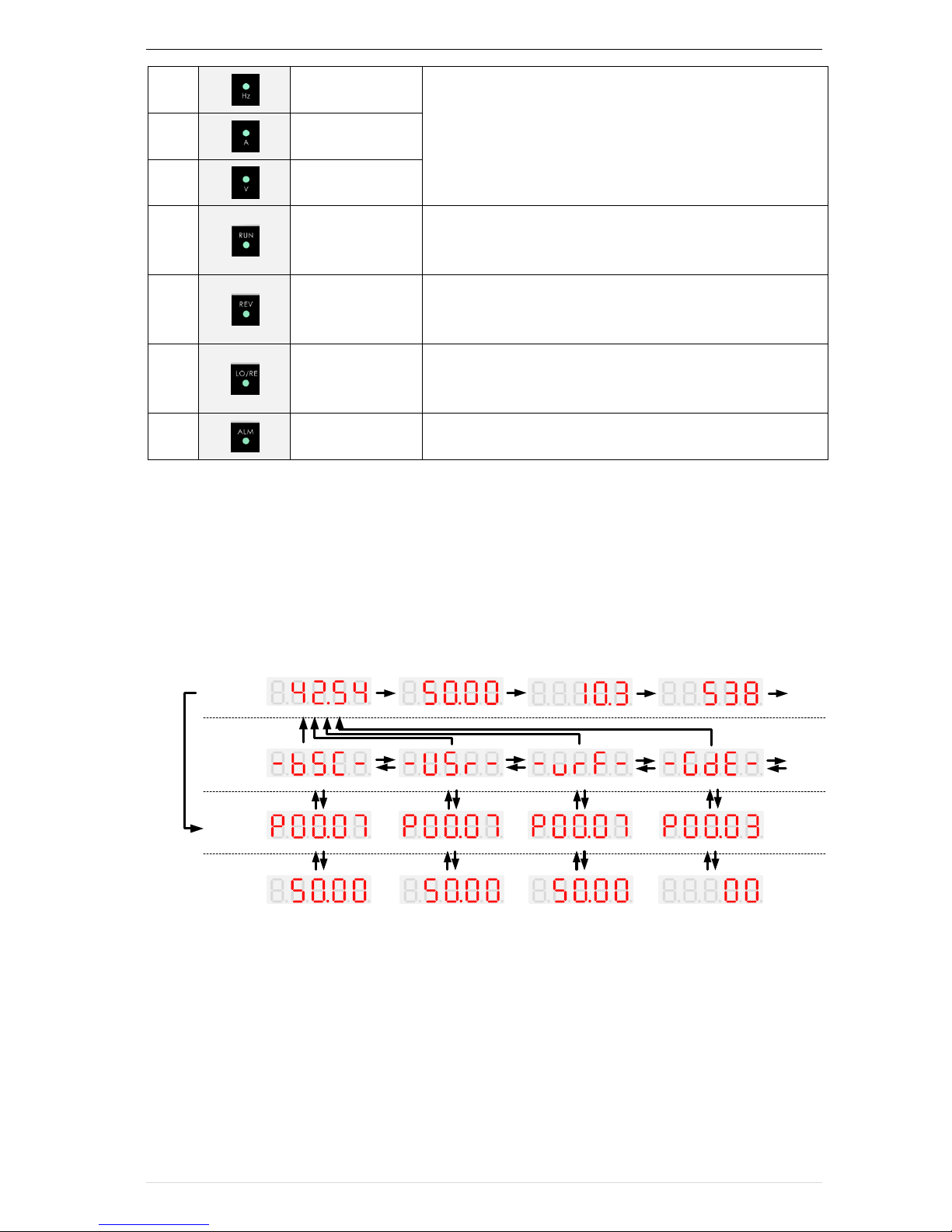
4.2 Display hierarchy and menu mode
VFD500 digital keyboard display is divided into four layers, from top to bottom are: monitoring status, menu
mode selection status, function code selection status, parameter editing / viewing status, as shown in Figure 4-2. In
the menu mode selection status, press 【UP】 or 【DOWN】 key to select menu mode, press 【ENTER】 to enter
the selected menu mode, the following describes several menu modes:
Wizard modeCheck mode
Standard mode
User-difined mode
ENTERESC
ENTERESC
UP
DOWN
UP
DOWN
UP
DOWN
“-bSC-
”
UP
DOWN
SHIF
T
SHIF
T
SHIF
T
SHIF
T
Monitoring volume1 Monitoring volume2
Monitoring volume3
Monitoring volume4
Monitoring
volume1
ESC
MONITO
R
STATUS
MENU
CHOOSE
STATE
COMMAND
CODE
PARAMETER
EDIT/VIEW
STATUS
ESC
ENTERESC ENTERESC
ENTERESC
ENTERESC ENTERESC ENTERESC
【UP、DOWN、SHIFT】 【UP、DOWN】 【UP、DOWN】 【UP、DOWN】
【UP、DOWN、SHIFT】 【UP、DOWN、SHIFT】 【UP、DOWN、SHIFT】 【UP、DOWN、SHIFT】
4-2Keyboard operation diagram
Standard mode(-bSC-)
If access (P00.01) is standard, all the function codes mentioned in this manual are accessible.
If access (P00.01) is the end user (in the state of user password lock), then only some function code can be
accessed.
User-difined mode(-USr-)
In this menu mode, only 20 user-defined parameters defined are displayed.
Chapter 4 Operation and display VFD500 high performance vector control frequency inverter user manual
- 25-
Verify mode(-vrF-)
In this menu mode, only parameters that differ from the factory settings are displayed。
Guide mode(-GdE-)
When users first use the inverter, can guide the user to complete a simple trial run。
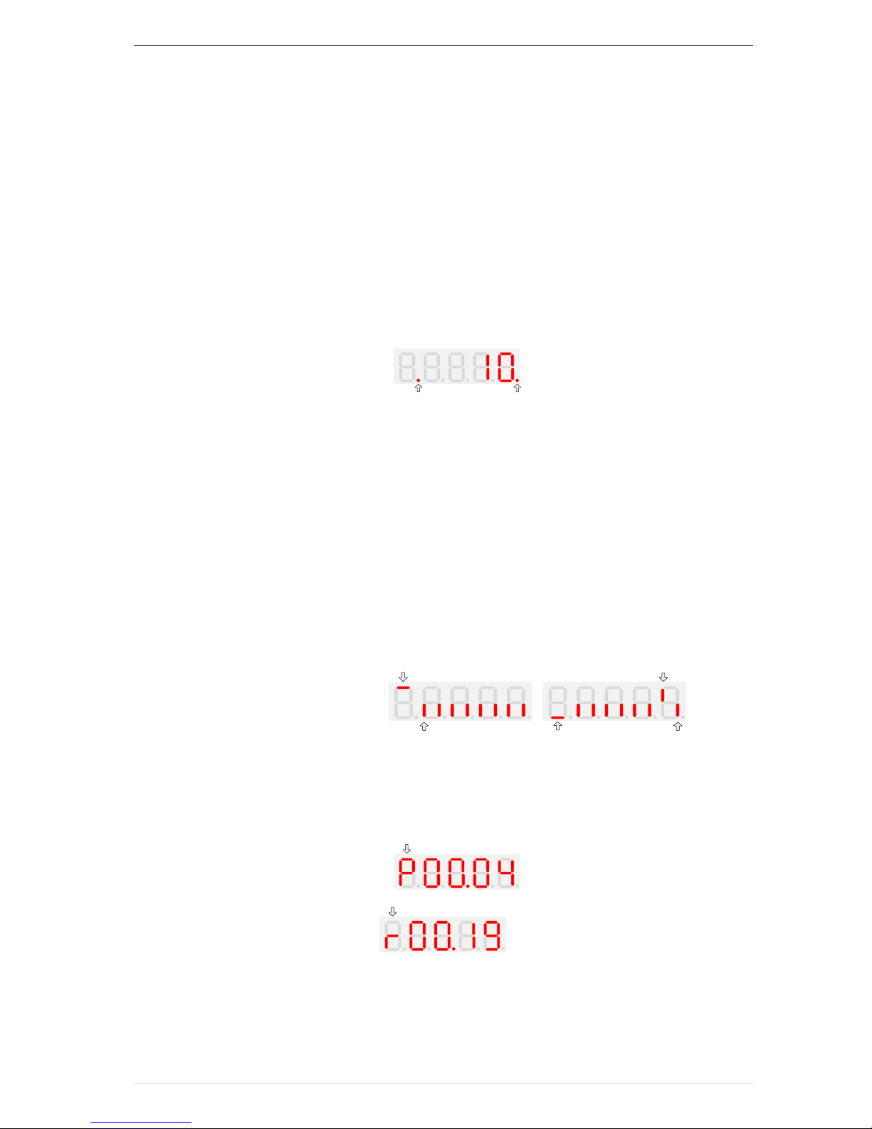
4.3 Digital tube display
Display of decimal data
16 digits:
The range of unsigned numbers is 0 ~ 65535 (without decimal point). The displayed range of signed numbers
is -9999 ~ 32767 (excluding decimal point). The negative numbers less than -9999 will be displayed as -9999.
32 digits:
The left and right screen display, combined with the following figure to illustrate:
Dot5
Dot1
Dot1 is used to distinguish between the left and right screens. On indicates the left panel (upper 5 digits) and turns
off the right screen (lower 5 digits). When the left screen is displayed, Dot5 is used to indicate the sign digit. On
indicates that the value is negative, off indicates the value is Positive.
The display range of 32-bit unsigned numbers is 0 to 4294967295 (excluding decimal point), and the displayed
range of signed numbers is -2147483648 to 2147483647 (excluding the decimal point).
Binary data display
Binary number currently only supports 16 digits, points left and right screen display.
The leftmost digital tube is used to distinguish the left and right screens: the top digit segment lights up for the left
panel and the bottom segment segment lights for the right panel.
Remove the leftmost digital tube, from right to left, followed by Bit0 ~ Bit15. The upper segment is lit to indicate 1, the
lower segment to light to indicate 0.
Means right
screen,low 5bit
Means left screen,high 8bit
bit1=1
bit0=0bit15=0
Parameter attribute identification
Editable parameters The leftmost LED displays "P"; the leftmost LED of the read-only parameter displays "r", as
shown below.
P means can edit
R means read only
Specific symbol
In some cases, the digital tube will display a specific symbol. The meaning of specific symbols is shown in the
following table:Table4-2 Digital tube display symbol and meaning
VFD500 high performance vector control frequency inverter user manual Chapter 4 Operation and display
- 26 -
Symbol
Meaning
tUnE
Motor parameter self-learning
bUSY
Processing parameter read and write requests
End
• Indicates that the parameters have been changed
and saved to the EEPROM
• The mission has been completed
Er.xxx
• Fault code, "XXX" is the fault type, see Chapter 6 for
details
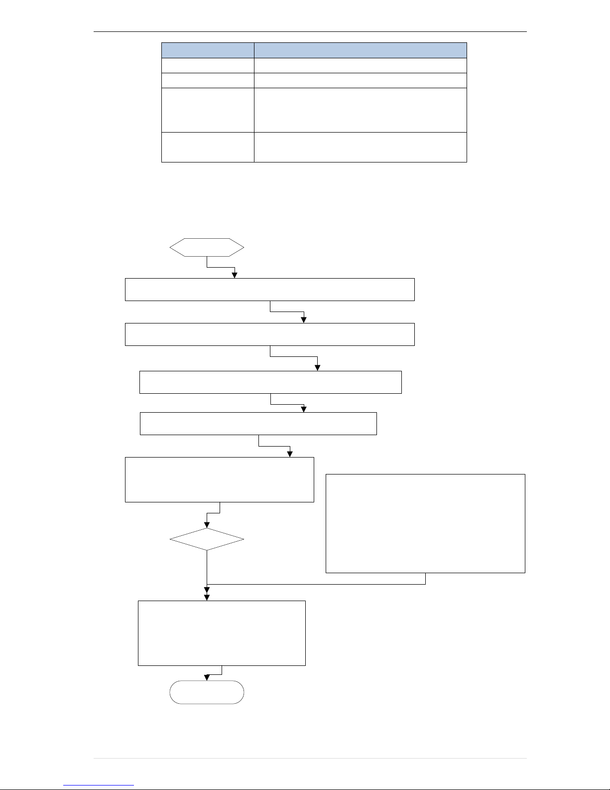
4.4 Test run
Please follow the procedure below to commission the first power-on。
start
Follow the instructions in Chapter 3 to install the inverter and wire it
Make sure the power cable, motor cable and brake unit are connected
correctly
Observe the safety precautions and switch on the power supply
Enter guide mode”-GdE-“
Set each parameter in turn according to the
guidance of the wizard, set the motor selflearning mode P11.10, press the run button,
waiting for the complete of self-learning
· Press “RUN”to Run inverter
· Press “STOP” to stop inverter
While monitoring the output frequency
or command frequency,press
“ENTER”to modify the target
frequency
End
close loop vector control(VC),Before normal
operation, ensure that the encoder P10.03 is in
the correct directionIf rotary self-learning is
performed, the encoder orientation can be
automatically recognized and storedIf it is not
executed, it needs to open the loop control to
run the motor and observe whether the encoder
feedback(r10.12) is in the same direction with
the given direction, if no,change as P10.03
Open control
Y
N
4-3Trial run flow chart

Chapter 5 Function code table VFD500 high performance vector control frequency inverter user manual
- 27-
Chapter 5 Function Code Table
The following is the VFD500 parameter distribution list:
classification
Parameter group
Page
Common
parameters
00:Basic function
Page29
01:frequency source selection
Page31
02:start and stop
Page 37
03:Ramp and S curve
Page 39
04: Analog and pulse input
Page 41
05:Analog and pulse output
Page 45
06:Digital input (DI)
Page 46
07:Digital output(DO)
Page 49
08:Digital Output setting
Page 51
Motor control
10:encoder type
Page 53
11:Motor1 parmeter
Page 54
12:Motor1 VFcontrol parameter
Page 56
13:Motor1 Vector controlparameter
Page 58
14:Torque control
Page 59
16:Energy saving control
Page 60
Display and
protection
20:User-defined parameters
Page 61
21:key pad and display
Page 62
22:AC Drive configuration
Page 64
23:Drive protection
Page 66
24:Motor protection
Page 69
25:Fault tracking parameter
Page 71
26:Fault recording parameter
Page 71
27:Monitoring parameter
Page 72
Communication
30:Modbus communication
Page 73
Application
40:Process PID
Page 74
41:Sleep function
Page 78
42:Simply PLC
Page 79
43:Programmable delay unit
Page 81
44:Comparator and logic unit
Page 83
45:Multifunction counter
Page 87
Motor 2
60:motor2 basic parameter
Page 88
61:motor2 parameter
Page 89
62:motor2 VF control parameter
Page 89
63:motor2 vector control parameter
Page 89
Term Description:
The parameter is also called function code; the operation panel is also called the keyboard.
Due to usage habits, different terms may be used in different places in this manual, but all refer to the same
content.
Symbol Description:
"☆" means that the setting value of this parameter can be changed when the inverter is stopped or running.
"★" means that the setting value of this parameter can not be changed when the inverter is running.
"●" indicates that the value of this parameter is the actual test record value, which can not be changed
 Loading...