

Veichi Electric AC60 series User Manual
Manual
AC60 series frequency inverter
Version V2.0

FOREWORD
Thank you for using AC60 series frequency inverter produced by Veich
Electric Co.LTD
AC60 series inverter is a new generation of high-performance universal
frequency inverter independently developed by Veich. With advanced control
method, we can provide products with a high-torque, high-precision, high
reliability and wide –speed- range drive. In the benefit of AC60 series'
multiple function design, users will be satisfied by the simplified PLC,
PID adjustor, programming I/O terminal, RS485 interface, pulse-frequency
I/O interface and other specific control functions for particular
industries. It offers a highly-integrated solution for equipment matching,
facilities upgrading, automation control and other specific industrial
application.
AC60 series adopts G/P all-in-one design, which facilitates users in
choosing and use the proper model.
This manual is the supporting data sheet for AC60
This instruction manual includes instructions (messages) of installing
wiring, parameters setting, troubleshooting, maintenances, related
matters attention and etc... For the best results and safe operations of
the AC60 series, pls carefully read and keep this manual. Make sure it is
handy for the ultimate user of the inverters for reference.
If you need technical support related to the inverter, please contact the
Veich sales office or the dealer from whom you purchased. You can also
contact our Customer Service Center. We will try our best to help you.
We are sparing no effort to upgrade our products, but regret for no prior
notification if there is any revision to this instruction manual. Pray for
your consideration for the inconveniences

Catalog
Chapter one Safety Requirement and Cautions…………………………………1
1.1 Safety definition……………………………………………………………1
1.2 Safety requirement and cautions…………………………………………1
1.3 Cautions in utilization……………………………………………………5
1.4 Cautions in disposal ………………………………………………………7
Chapter two Purchase Inspection and Products Specification ………………8
2.1 Purchase inspection ………………………………………………………8
2.2 Nameplate and models illustration ………………………………………8
2.3 Product technique specifications………………………………………9
2.4 Inverter rated output current …………………………………………11
Charter three Installation ………………………………………………………13
3.1 Installation environmental requirements……………………………13
3.2 Products appearance and components title……………………………14
3.3 Mounting direction and space …………………………………………14
3.4 Dismantle and install tail-hood……………………………………15
3.5 Dismantle and install keyboard………………………………………16
3.6 Installation size ………………………………………………………17
3.7 Operation keyboard size…………………………………………………22
Chapter four Frequency Inverter Wiring………………………………………23
4.1 Wiring attentions ………………………………………………………23
4.2 Basic wiring diagram……………………………………………………25
4.3 Main circuit terminals…………………………………………………27
4.4 Electrical specifications recommendation …………………………29
4.5 Control circuit terminals………………………………………………30
4.6 RS485 communication modules and control panels jump circuit
specification ……………………………………………………………………… 31
4.7 Backup circuit…………………………………………………………… 33
Chapter five Keyboard Operation and Usage……………………………………34
5.1 Keyboard layout and functions specification…………………………34
5.2 Indicating lamp meaning specification………………………………37
5.3 Keyboard operation mode…………………………………………………38
Chapter six Functional Parameter Table…………………………………………43
6.1 Basic parameter……………………………………………………………43

6.2 Exterior terminal parameters……………………………………………50
6.3 Special functions parameter……………………………………………58
Chapter seven Function Detailed Specification………………………………64
7.1 Basic parameters detailed specification……………………………64
7.2 External terminal parameters detailed description………………105
7.3 Special function parameters……………………………………………130
Chapter eight Abnormality Diagnoses and Processing…………………………152
8.1 Fault information and troubleshooting………………………………152
8.2 Common fault and processing methods…………………………………157
Chapter nine Overhaul and Maintenance…………………………………………165
9.1 Inspection and maintenance……………………………………………165
9.2 Components needed periodic replace……………………………………166
9.3 Preservation and maintenance…………………………………………167
9.4 Measurement and judgment………………………………………………167
Chapter ten Optional parts………………………………………………………169
10.1 Alternating current reactor…………………………………………170
10.2 Noise filter………………………………………………………………170
10.3 Braking unit and braking resistor……………………………………170
10.4 Capacitance box…………………………………………………………171
Chapter eleven Quality Guarantee………………………………………………172
11.1 “Three guarantee” service…………………………………………172
11.2 Lifelong paid service…………………………………………………172
11.3 Service provider…………………………………………………………172
11.4 “Three guarantee” service responsibility………………………172
11.5 “Three guarantee” service range……………………………………172
11.6 “Three guarantee” service premise………………………………172
Chapter twelve Appendix ……………………………………………………173
Appendix one: RS485 communication protocol …………………………………174

Chapter one Safety Requirement and Cautions
To ensure safety of your health, equipment and property, please read this
chapter carefully before use the frequency inverter and act in compliance with
the instructions while carrying, installing, debugging, running and
overhauling the frequency inverter.
1.1 Safety definition
Danger: it will cause danger of serious injuries and even death while operating
against the rules
Caution: it will cause danger of light injuries or equipment destruction while
operating against the rules
Note: some information is useful while operating and use frequency inverter.
1.2 Safety requirements and cautions
●Before installation
Danger
1. Only qualified personnel can operate the equipment. Before operating,
be sure to carefully read the manual about safety, installation,
operation and maintenance. The safe operation depends on the proper
processes of choosing models, carrying, installation, operation and
maintenance.
Danger
1. Don’t use the damaged or incomplete frequency inverters; Otherwise,
there is risk of injury.
●Installation
1

Danger
1. Please install the frequency inverter on metal or other nonflammable
material, and keep it away from the combustible material. Otherwise
there is danger of fire;
2. No unauthorized modification to the frequency inverter; Otherwise
there is danger of damaged.
3. Normal frequency inverter, which is not explosion-proof, can not be
installed where with explosive gas or dust; Otherwise there is
danger of explosion.
Attention
1. When two frequency inverters are installed in the same control cabinet,
pleas pay attention to the installing place to guarantee the effective
heat dissipation.
2. When carrying the frequency inverter,please support its bottom.
Wiring
Danger
1. Wire is connected only when the main circuit is cut off, otherwise
there is a danger of shock.
2. Wire is connected by professional person only. Otherwise there is a
danger of shock.
3. Earth must be reliable. Otherwise there is a danger of shock.
4. AC power supply should not be connected with output ports U, V, W;
Otherwise there is a danger of damage to frequency inverter.
5. No drop of bolt, spacer, metal stick, conducting wire or other things
into the inner of frequency inverter; Otherwise there is a danger of
fire or damage to frequency inverter.
Attention
2

1. If the damage to frequency inverter or other equipment is caused by
improper wiring and utilization or unauthorized alteration, the user
should shoulder all responsibilities.
2. Please make sure all wirings meet EMC requirement and satisfy safety
standard in the local area; Please refer to recommendations in this
manual or national standards of wire diameter to avoid accidents.
3. Please connect the braking resistance or braking unit according to the
wire diagram; Braking resistance can not be connected to the terminals
of DC bus P(+)、N(-); Otherwise it will cause fire or damage to frequency
inverter.
4.Human body electrostatic would seriously damage internal MOS
transistor,etc. No touch the printed circuit boards, IGBT or other
internal devices without anti-static measures, otherwise it will cause
the malfunction of frequency inverter.
5. Please don't connet phase shifter capacitance or LC/RC noise filter
to the output circuit of frequency inverter; Otherwise it will damage
the frequency inverter.
6. Please don't connect the magnetic switch or magnetic contactor to the
output circuit of frequency inverter; When frequency inverter is in the
operation with load, magnetic switch or magnetic contactor can make
inverter overcurrent protection function act, that will damage frequency
inverter seriously.
7. Please don't disassemble the panel cover, it only needs to disassemble
the terminal cover when wiring.
8. It is forbidden to do any pressure test on frequency inverter;Otherwise
it will damage the frequency inverter.
●Before electrification
Danger
3

1. Please make sure that voltage grade of power supply is consistent with
frequency inverter's voltage and then check whether the wiring is correct
and firm, and whether there is short circuit in peripheral equipment's
circuit. Otherwise it will damage frequency inverter and other
equipments.
2. Before the frequency inverter is connected to the input power supply,
make sure that the cover has been fixed well. Otherwise it will cause
electric shock.
3. For the frequency inverters whose storage time is over 1 year, when
electrification, the voltage should be raised by booster from low to
high. Otherwise it will damage the frequency inverter.
Attention
1. Check all periphery fittings are wired properly according to the
handbook; Otherwise it will cause accidents.
● After electrification
Danger
1. After electrified, it is forbidden to open the cover, make wiring, and
check up; Otherwise, it will cause the danger of electric shock.
2.After electrified, it is forbidden to contact internal wiring board and
its parts. Otherwise it will cause the danger of electric shock.
3.Do not operate or touch frequency inverter with wet hand. Otherwise there
is dangers of damage to frequency inverter and electric shock.
Attention
1. Pleasea set the parameter of frequency inverter cautiously; Otherwise
it will damage equipment.
●Operation
Danger
4

1. Before running, please check and confirm the application range of the
machine and equipments once more; Otherwise it will cause accidents.
2. Please don't touch the cooling fan and braking resistance to check the
temperature; Otherwise there is a danger of getting burn.
3.Unprofessional workers are banned to check the signals in the running
stage; Otherwise it will cause injuries and damage the equipment.
Attention
1. Please don't turn off the equipment by switching off power; Please cut
off the power supply after the electric machine stops running; Otherwise
it will damage the frequency inverter.
2.Please avoid anything dropping into the equipment when the frequency
inverter is running; Otherwise it will cause electric shock..
●Maintenance
Danger
1. Please don't maintain and repair the equipment with electric; Otherwise
it will cause electric shock.
2. Before maintaining and repairing the frequency inverter, please make
sure the indicator lights of power supply have completely turned off;
Otherwise it may cause electric shock and damage the frequency inverter.
3. Persons who have not passed specialized train are not allowed to conduct
the frequency inverter maintenance; Otherwise it may cause electric
shock and damage the frequency inverter.
1.3 Cautions in utilization
1. The general motor running at a low speed decreases its lifelime for the
heat dissipation effect is quite bad. If low speed running needs to last
for a long time, the frequency inverter special-purpose motor should be
chosen or the load should be lightened.
2. When using the frequency inverter, the temperature of motor is a little
5

higher comparing to the power frequency operation. It is normal phenomena.
3. In application of AC60 series frequency inverter, you have to confirm
all machine insulation to prevent damage to the equipment. Moreover, when
the motor working in tough environment, please periodic inspect the
electrical insulation to ensure the safety of the system work.
4. If the motor adapter is not consistent with frequency inverter's rating
current ( The rating current of the motor is far smaller than that of
frequency inverter), please adjust the protective value to ensure safe
running.
5. In occasions such as load raising, usually there is negative torque and
frequency inverter breaks off for over-current or over-voltagte. In this
case, you should consider to choose matching brake unit.
6. Frequency inverter, in a certain output frequency range, can meet the
load equipment’mechanical resonance. To avoid it, you can set up jumping
frequency.
7. As output voltage of the inverter is pulse-wave type, if there is capacity
which can improve power factor or pressure-sensitive resistance which used
for thunder-proof in the voltage output side, the frequency inverter will
break off or its parts will be damaged, so it is necessary to dismantle
them. Moreover, it is proposed not install switch parts like air switch
and contactor (if it is necessary to install switch on output side, please
make sure the output electricity of frequency inverter is zero when the
switche is working)
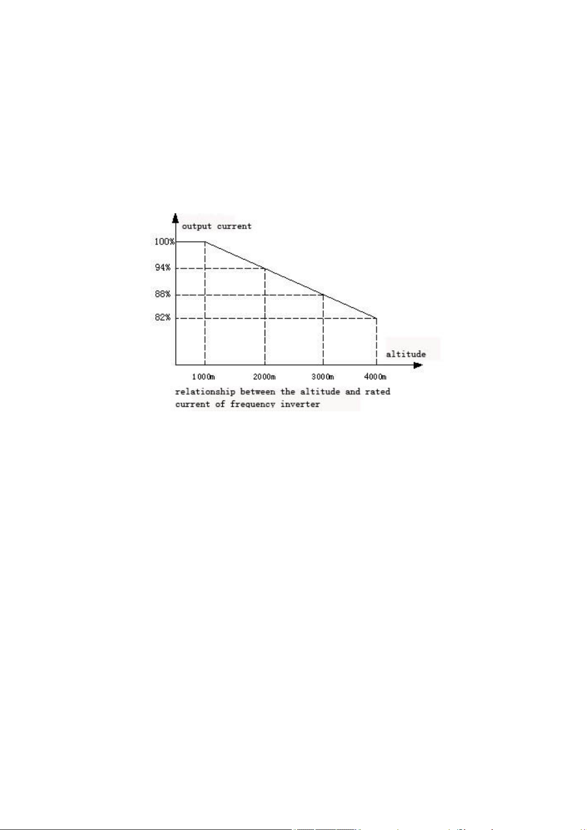
8. At over 1,000 meters altitude, the inverter’s heat dissipation function
worsened due to the thin air, it is necessary to derate use.
9. The inverter output voltage is pulse wave type. If use digital multimeter
measurement, deviation of the reading will be great. And the deviation is
different by using different type of digital multimeter. Under normal
circumstances, while RMS 380V, digital multimeter reading is around 450V.
6

1.4 Cautions in disposal
When you dispose frequency inverter, please pay attention to:
1. Electrolytic capacitor: the electrolytic capacitor of main circuit or the
printing plate may explode when they are burned.
2. Plastic: plastic incineration may generate toxic gases.
3. Dispose method: please dispose as industrial waste.
7
Chapter two Purchase Inspections and Products Specification
2.1 Purchase inspection
1. Before unpacking, please confirm whether there is any damage occurred during
transportation.
2. Check whether the details on the nameplate of frequency inverter are in
accordance with your order.
3. AC60 series frequency inverter have undergone a rigorous testing and quality
control before leaving the factory. Please check all of qualified
certification, product manual and warranty cards.
4. Please check the frequency inverter to ensure it without any internal damage.
If it has obvious damage, please do not operate machine and timely contact
the manufacturer or distribution company, in order to avoid the accidents.
Nameplate and models illustration
2.2
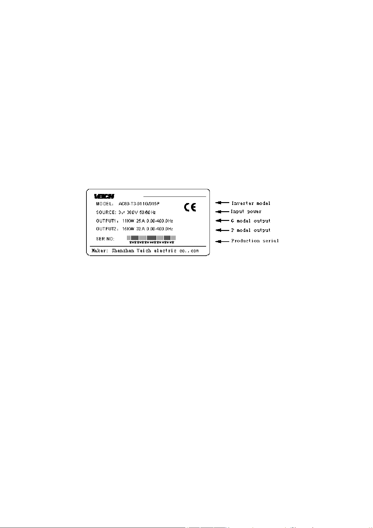
1. Nameplate illustrate
2. Models illustration
8
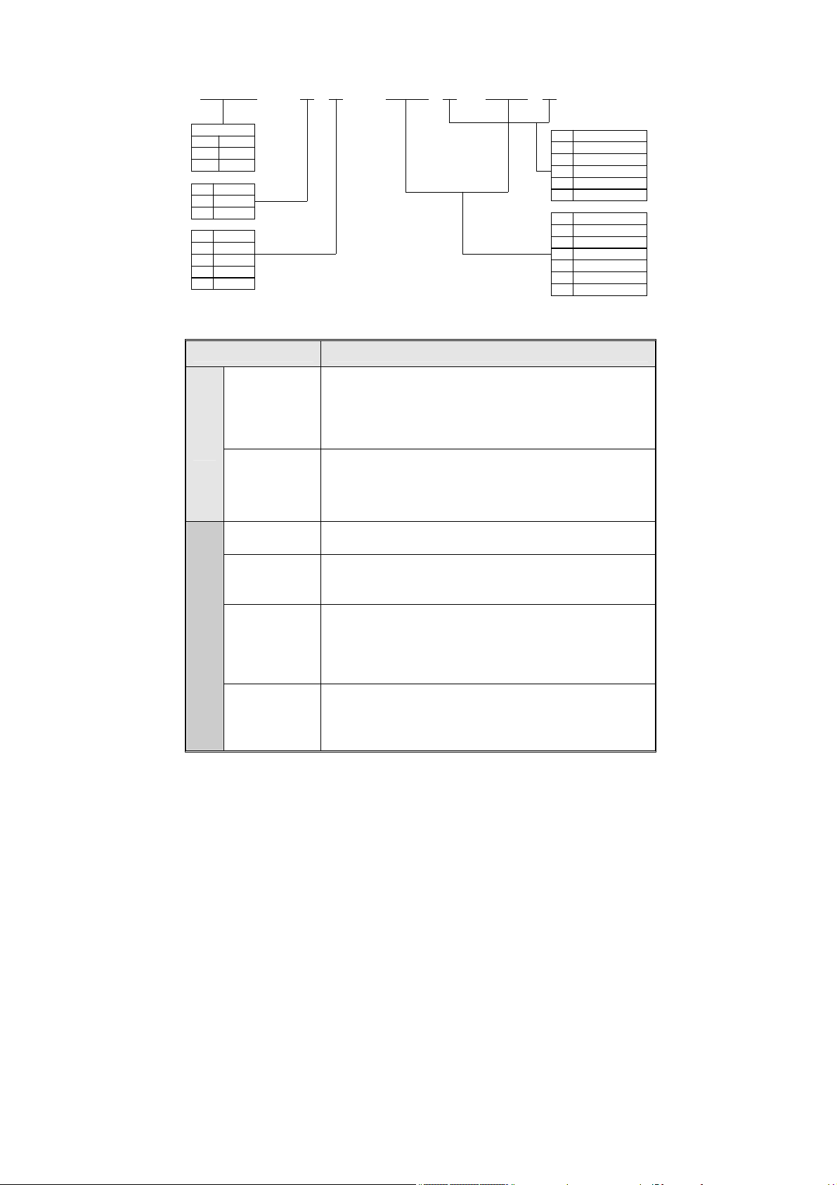
AC60 - T 3 - 015 G /018 P
inverter series
general format
AC60
injrction mold i n g
AC61
machine
draw bench
AC62
voltage class
code
three phase
T
single phase
S
voltage class
code
2 220V
3 380V
6 660V
11 1140V
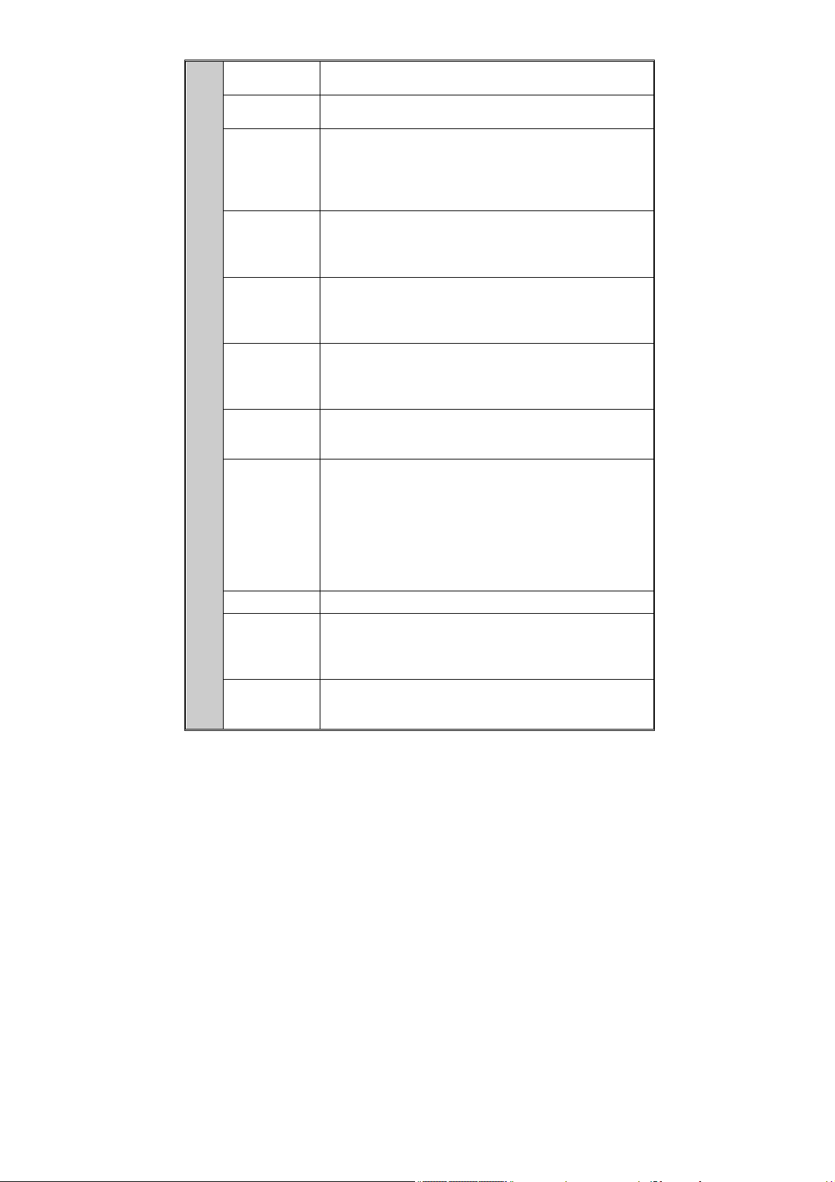
2.3 Product technique specifications
Items Specifications
Single phase 220V 50/60Hz
Voltage 、
frequency
Pow
er
Allowable
fluctuations
Frequency
control range
Output
frequency
accuracy
Con
Frequency
tro
setting
l
resolution
Voltage/freq
uency
characterist
ics
Three phase 220V 50/60Hz
Three phase380V 50/60Hz
Three phase660V 50/60Hz
Three phase 1140V 50/60Hz
voltage:±15%, frequency:±5%
G:0-400Hz P:0-400Hz Z:0-400Hz、
L:0-400Hz H:0-2000Hz
±0.5% of max frequency
0.01Hz:Operating“up”and”down”keys on keyboard
0.2Hz:Potentiometers analog input
Voltage 50% -100% the rated voltage adjustable,
Motor rated frequency 25-400Hz(2000Hz) adjustable
inverter type
code
general format
G
blower and water pump
P
plastic machine
Z
L
draw bench
mid inverter governor
H
fit power of motor(kW)
code
7R5
011
015
018
022
030
7.5
11
15
18
22
30
9
Carrier
frequency
Torque
upgrade
Maximum
Capacity
Acceleration
and
Deceleration
time
Rated output
voltage
Automatic
voltage
adjustment
function
Automatic
energy-savin
g operation
Standard
functions
Brake Energy-consuming braking, DC braking
Frequency
setting input
Signal
Feedback
input
1.0-15.0KHz、Random carrier modulation
0~25.0% adjustable、auto torque upgrade、random V/F
curve optional
G、H、L model:150% for one minute, 180% for 2s, 200%
instant jump.
Z model:150% for one minute, 180% for 30s ,250% instant
jump.
P model:120% for one minute, 150% instant jump.
0.1-6500s
Take advantage of the power supply voltage
compensation function, if motor rated voltage is
100%,the voltage can be set in the 50 -100% scope(the
voltage output should not exceed the input voltage )
When the grid voltage fluctuates, changes in the
output voltage is very small, remained constant V /
F
According to the load conditions, automatic optimize
the V / F curves to implement energy saving operation
PID control, Acceleration and deceleration time
adjustable, Acceleration and deceleration mode
variable, Carrier frequency adjustment, Torque
upgrade, Current limiting, Speed tracking and
restart, Frequency hopping, Frequency fluctuation
limite control, Program running, Multi-steps speed,
Pendulum frequency operation, RS485, Analog output,
Pulse output frequency
Keyboard number settings, keyboard potentiometers、
external terminal VS1 : 0 ~ 10V, external terminal VS2:
- 10V - 10V, the external terminal AS : 4-20mA, RS485
and signal composition and terminal options
External terminal VS1 : 0 ~ 10V, external terminals
VS2:-10V - 10V, external terminal AS : 4-20mA, RS485,
frequency pulse input
10

Start, stop, positive and negative rotating , jog,
Input order
signals
External
output signal
Protection function
Setting Function number、data
Running
Dis
pla
y
Fault
Installation
sites
Temperature,
humidity
Vibration Below 20Hz less than 0.5g
Con
Storage
dit
Temperature
ion
Installation
mode
Protection
degree
Cooling Mode Forced air-cooling
multi-steps speed, free parking, reset, acceleration
and deceleration time choice, frequency settings
channels choice, external malfunctions alarm
Relay output, the collector output, 0-10V output,
4-20mA output, the frequency pulse output
Overvoltage, undervoltage, current limiting,
over-current, overload, electric thermal relays,
overheat, pressure stall, data protection
Output frequency, give frequency, output current,
input voltage, output voltage, motor speed, PID
feedback, quantitative PID, module temperature, input
and output terminal
Overvoltage, undervoltage, overcurrent, short
circuit, phase missing, overload, heat, pressure
stall, current limiting, data protection is damaged,
current fault operating conditions, historical fault
Indoor, elevation of not more than 1000 m, no corrosive
gases and direct sunlight
-10—+40℃, 20%—90%RH(No condensation)
-25—+65℃
Wall-mounted mode, closet mode
IP20
2.4 Inverter rated output current
Input
current
Rated power
0.4 2.5
220V 380V 660V 1140V
Rated output
current(A)
Rated output
current(A)
11
Rated output
current(A)
Rated output
current(A)

0.75 4 2.3
1.5 7 3.7
2.2 10 5.0
3.7 16 8.5
5.5 20 13
7.5 30 17
11 42 25
15 55 32 18
18.5 70 38 22
22 80 45 28
30 110 60 35
37 130 75 45 25
45 160 90 52 31
55 200 110 63 38
75 260 150 86 52
93 320 180 98 58
110 380 210 121 75
132 420 250 150 86
160 550 310 175 105
185 600 340 198 115
200 660 380 218 132
220 720 415 235 144
250 470 270 162
280 510 330 175
315 600 345 208
355 670 380 220
400 750 430 260
500
560 990 600 365
630 1100 680 400
700 1260 750 480
860 540 325
10
15
12
Charter three Installation
3.1 Installation environmental requirements
1.Ambient temperature: -10℃~40℃, good ventilation and heat dissipation. If
the temperature is higher than 40 ℃. The frequency inverter should be
derated to use.
2. Avoid vibration, free of direct sunlight and away from heat sources.
3. Inverter installed under the altitude of 1000m can output rated power. It
needs be derated to use when the altitude is more than 1,000 m . Pls refer
specific figures as below :
4. Humidity should be lower than 90% (no condensation); Avoid high temperature
and high humidity.
5. Be away from oil, salt and corrosive gases.
6. Prevent inverter from intrusion of water drop, steam, dust, wooland metal
dust.
7. Prevent electromagnetic interference, away from sources of interference.
13
8. Prohibit use of flammable, explosive gases, liquids or solids in a dangerous
environment.
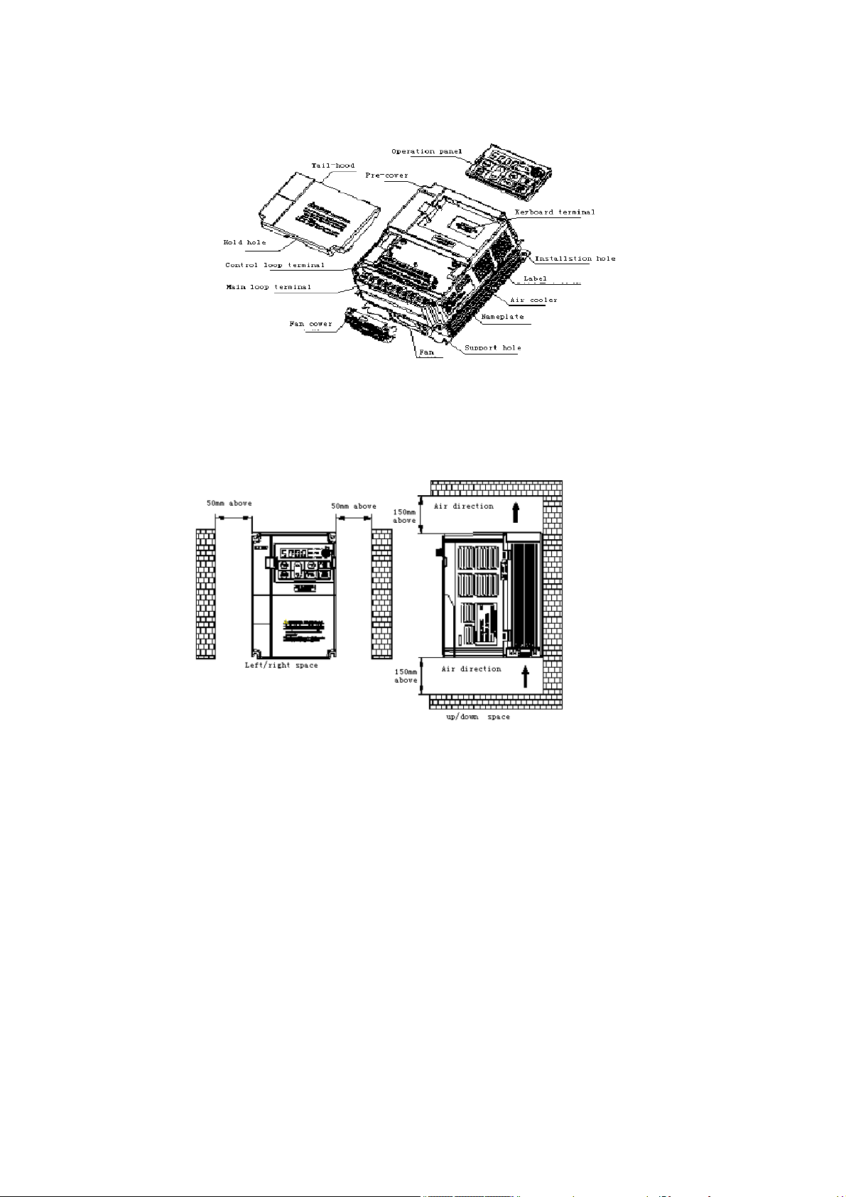
3.2 Products appearance and components titles
3.3 Mounting direction and space
Frequency inverter should be installed in a well-ventilated indoor place, and
adapt wall-mounted or closet-style vertical installation. Enough space with
the surrounding adjacent items or baffle (wall) shound be preserved.
Installation for one frequency inverter
14
When several frequency inverters are installed in one cabinet, you should pay
attention to the uniformity of each frequency inverter heat dissipation. While
it adopts vertical juxtaposition installation, you should install deflector
plate to avoid the heat of below inverter flows through the above inverter.
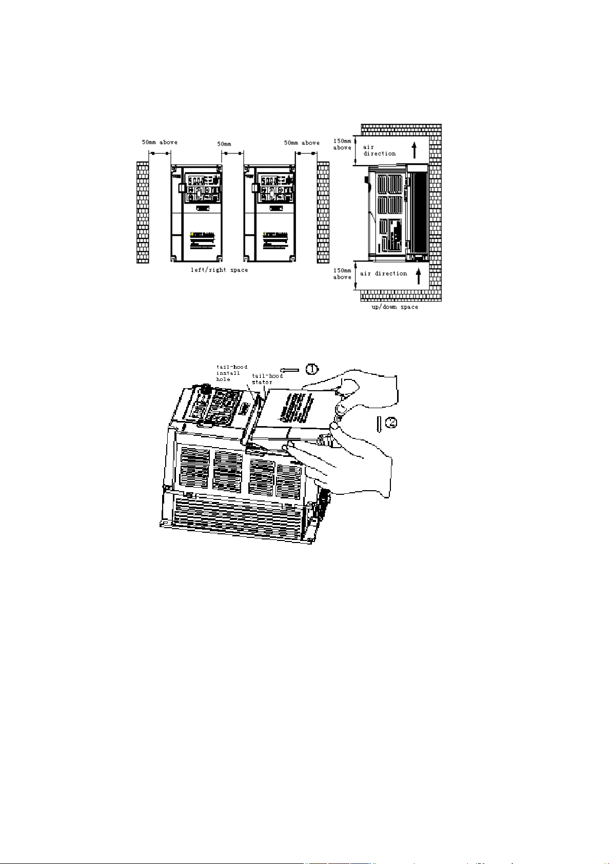
Installation for multi frequency inverter
3.4 Dismantle and install tail-hood
15
Installation: First the tail-hood upwardly inclines around 15 degrees and
inserts the top fixed flat into the fixed hole in the front cover. Then slightly
press the tail-hood downward. While your hear "Ka",it means that the tail-hood
is into the place.
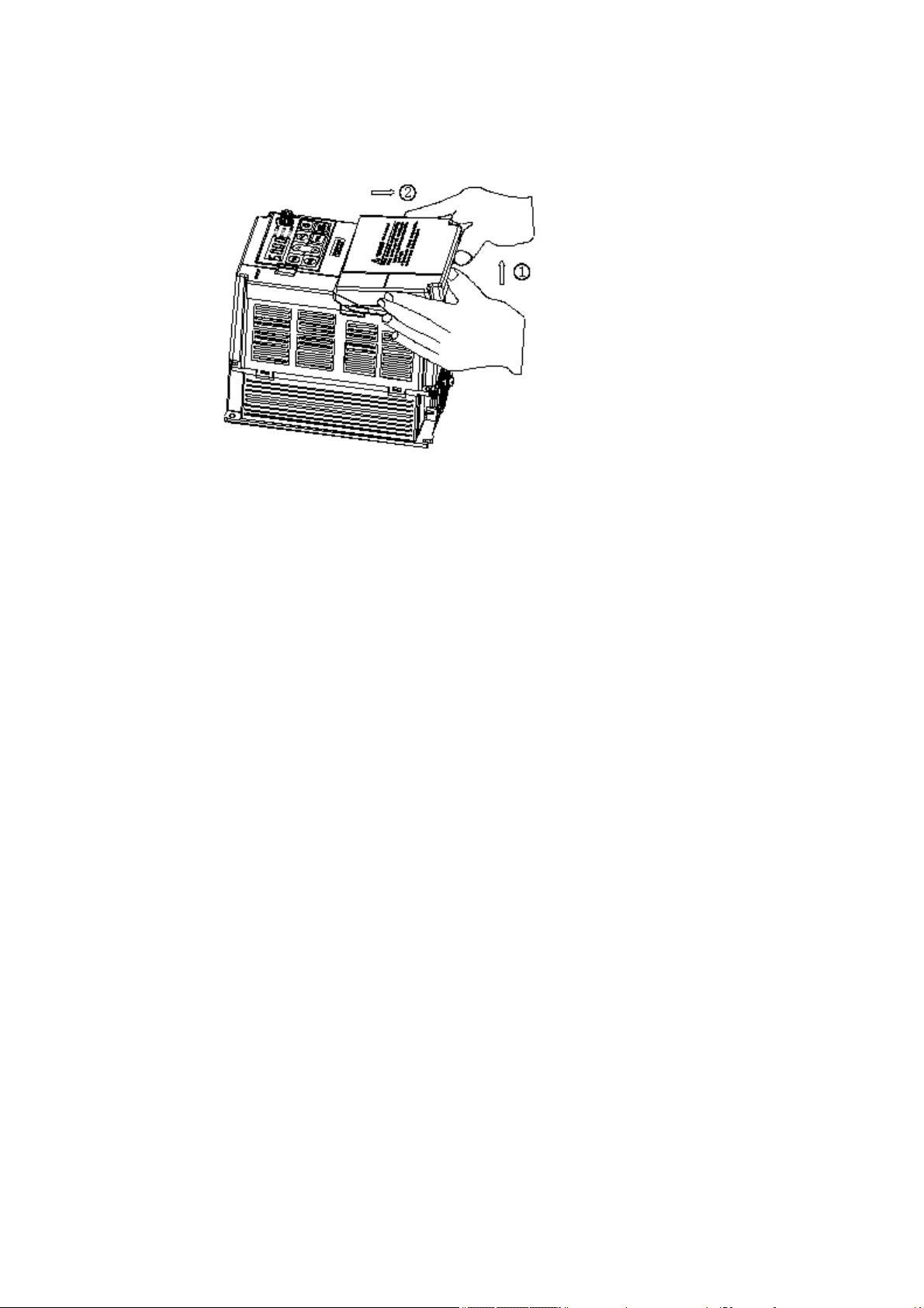
Dismantlement: At the tail of the frequency inverter, there is a special
dismantlement hole design. Put your fingers into the hole, upwardly pull the
cover with a little force until the buckle between the tail-hood and the crust
tear off, and then removed tail-hood down.
3.5 Dismantle and install keyboard
Installation : Put down the keyboard aimed at keyboard installation groove,
maintain the keyboard and cover parallel, press the keyboard down with uniform
strength until you hear "Ka" which means the installation of the keyboard in
place. Please do not tilt the installation of the keyboard.
16
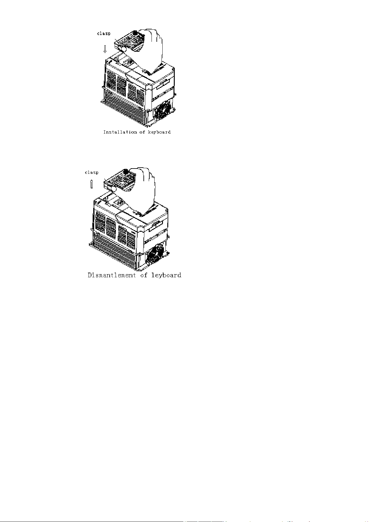
Dismantlement: Put your finger into the keyboard dismantlement hole and pull
the keyboard out.
3.6 Installation size(units:mm)
3.6.1 Installation size of machine with plastic cover
17
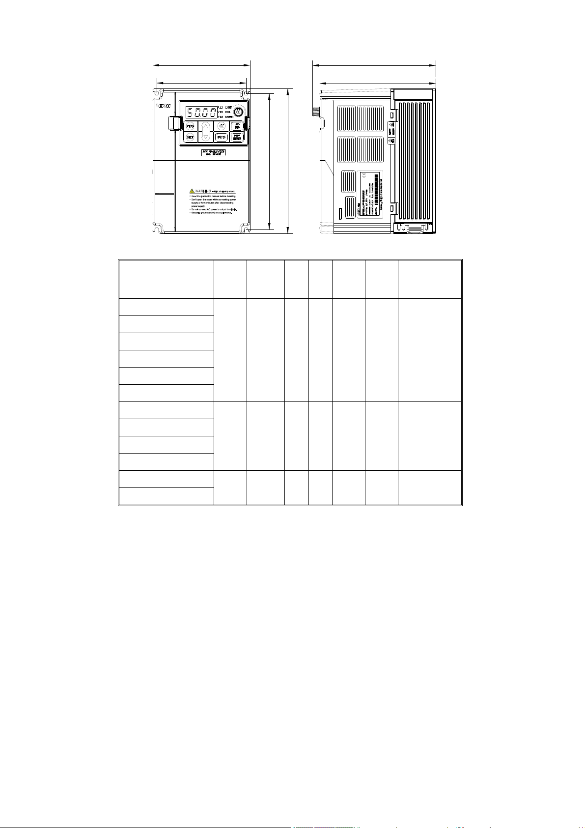
W
D
W1
Frequency inverter
G: Constant torque load
P: Fans&pump load
AC60-S2-R40G
AC60-S2-R75G
AC60-S2-1R5G
AC60-T3-R75G/1R5P
D1
H
H1
W W1 H H1 D D1
122 112 182 171 154.5 145 ф5
Installation
aperture
AC60-T3-1R5G/2R2P
AC60-T3-2R2G/3R7P
AC60-S2-2R2G
AC60-S2-3R7G
AC60-T3-3R7G/5R5P
AC60-T3-5R5G/7R5P
AC60-T3-7R5G/011P
AC60-T3-011G/015P
3.6.2 Wall-mounted machines installation size
159 147.2 246 236 157.5 148 ф5.5
195 179 291 275 167.5 158 ф7
18
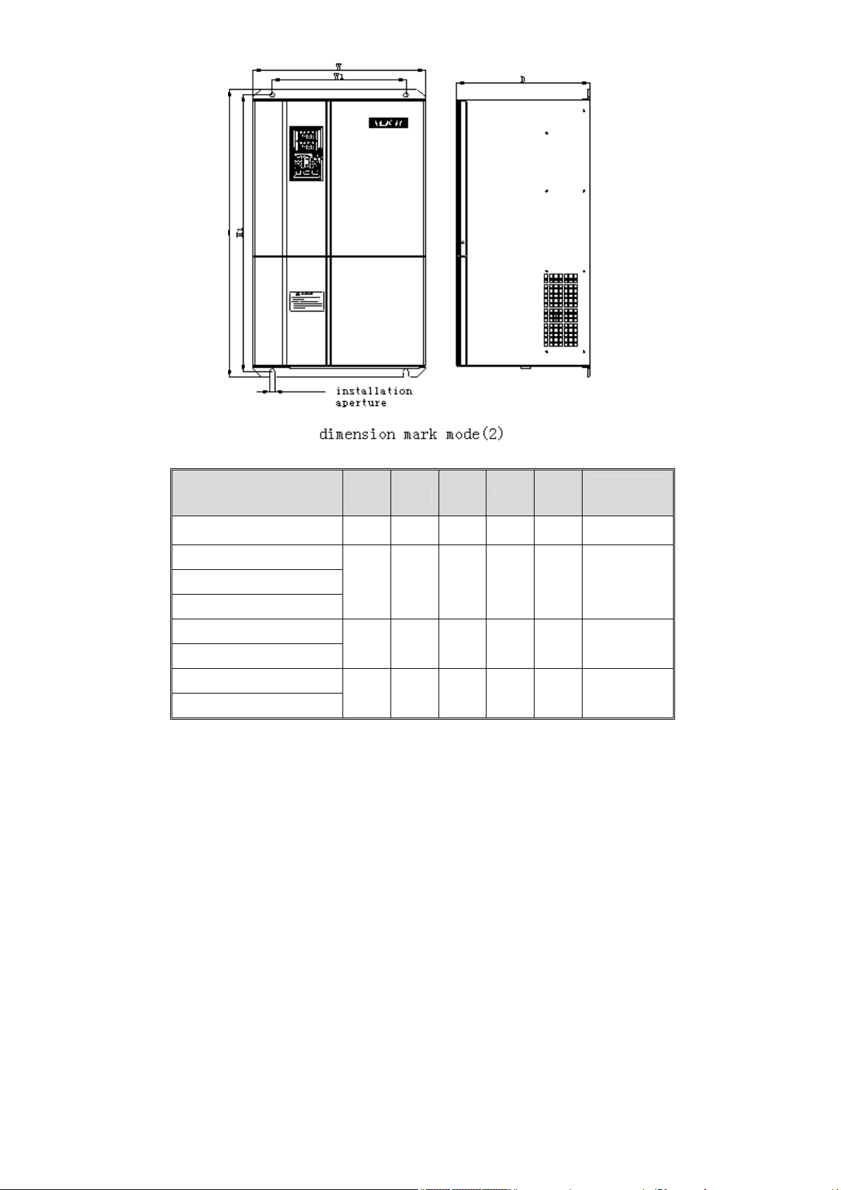
Frequency inverter
G: Constant torque load
P: Fans&pump load
W W1 H H1 D
AC60-T3-015G/018P 238 180 390 377 212 ф7
AC60-T3-018G/022P
Installation
aperture
AC60-T3-022G/030P
281 200 496 476 256 ф9
AC60-T3-030G/037P
AC60-T3-037G/045P
353 200 600 578 286 ф11
AC60-T3-045G/055P
AC60-T3-055G/075P
380 300 645 620 297 ф11
AC60-T3-075G/093P
3.6.3 Wall-mounted & Cabinet-mounted machines installation size
19
.
W1
W2
WD
RPM
VA
Hz
RPM%%
A
V
Hz
PRG
SET
STOP
REV
FWD
JOG
RESET
H
bottom entering
line hole
A1
Frequency inverter
G: Constant torque load
P: Fans&pump load
AC60-T3-093G/110P
VEICH
E
L1
the hole only
to 93-132G
L
H1
C
B1
1.User can enter line from bottom or back, detail according to below list.
2.Machine cabinet can be installed in ground with 4pcs foundation bolts
Size marker mode diagram(4)
H H1 L L1 W W1 W2 D E A1 B1 C
Sepcification
back entering
line hole
AC60-T3-110G/132P
AC60-T3-132G/160P
AC60-T3-160G/185P
AC60-T3-185G/200P
AC60-T3-200G/220P
AC60-T3-220G/250P
1200 450 780 755 515 350 -- 340 ф11 486 200 ф9
1588 440 1188 1155 600 450 150 370 ф13 565 250 ф9
1748 550 1238 1205 700 580 220 380 ф15 665 250 ф9
20

In the table, H is the height of whole machine plus bottom section. The customers
can choose installation made according to demand. Cabinet, lean against the
well, or other installation mode are ok. And you can also choose hang-style
machine and bottom section which consist the cabinet machine installed directly
in installation slot or ground。
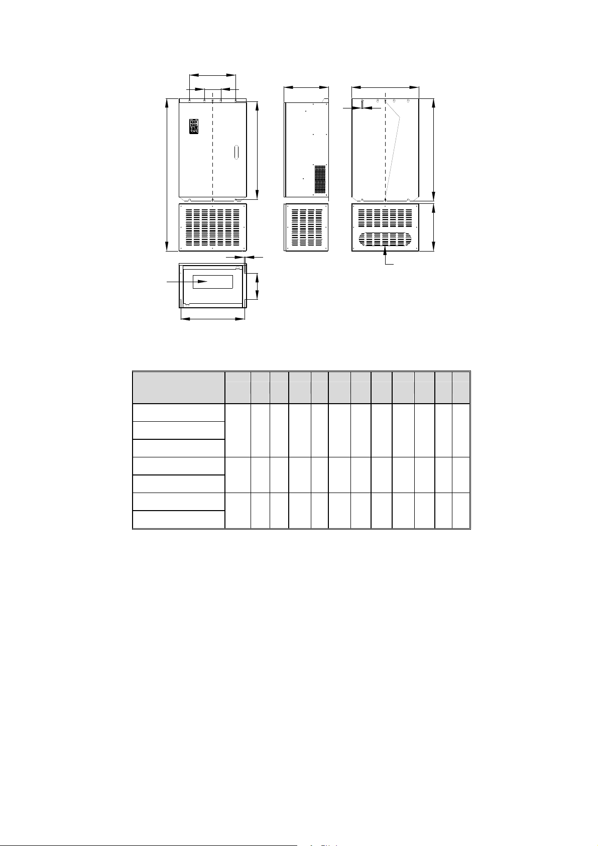
3.6.4 Cabinet-style machines installation size
Insta
Frequency inverter
G: Constant torque load
P: Fans&pump load
W W1 H L1 D
llati
on
apert
ure
AC60-T3-250G/280P
760 540 1700 270 485 ф13
AC60-T3-280G/315P
AC60-T3-315G/355P
AC60-T3-355G/400P
AC60-T3-400G/450P
AC60-T3-450G/500P
AC60-T3-500G/560P
AC60-T3-560G/630P
808 540 1800 270 485 ф13
1200 900 2200 320 550 ф13
21
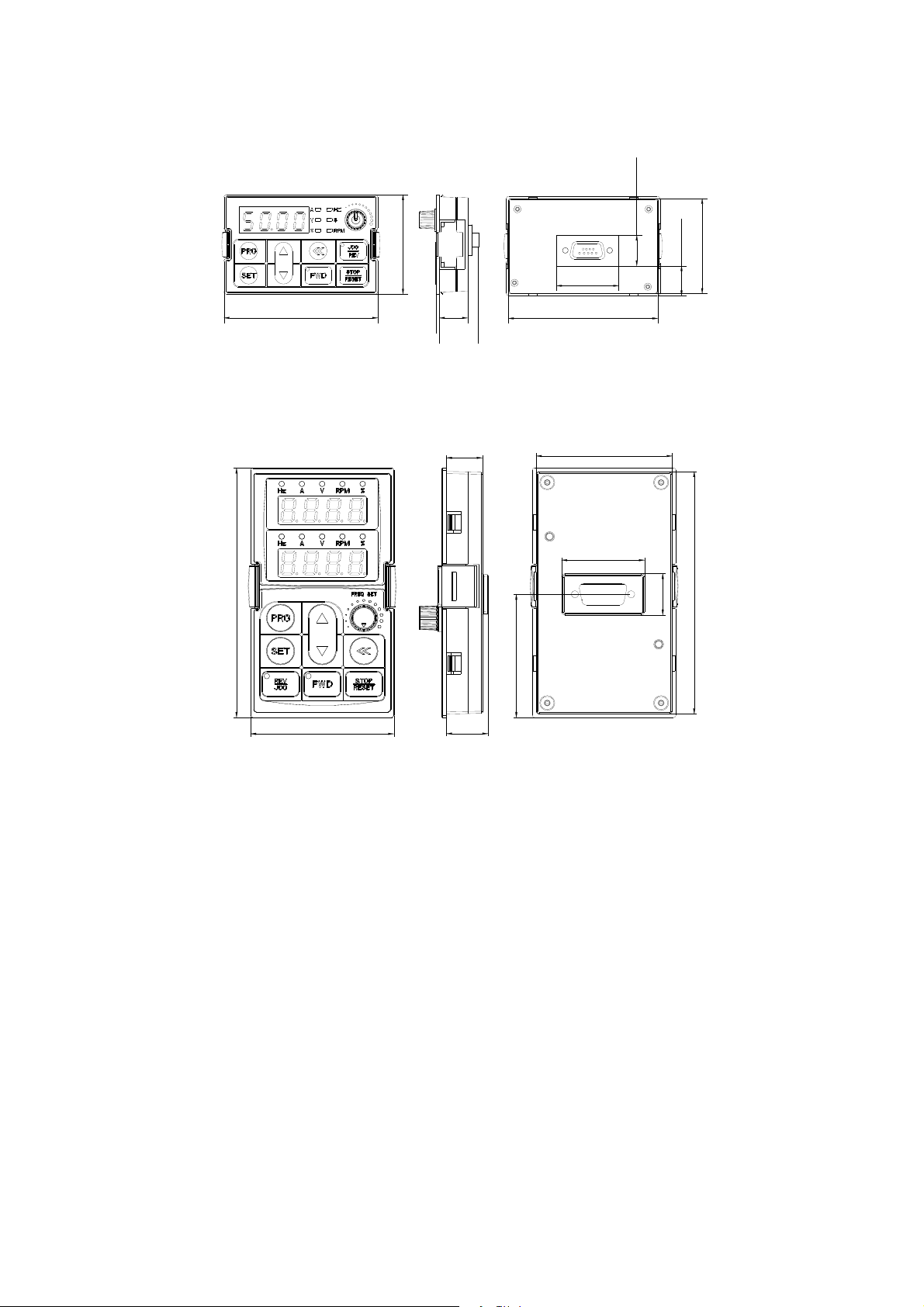
3.7 Operation keyboard size
3.7.1. Single display keyboard size
56.7
35.1
17.5
17.1
54.2
86.7
3.7.2 Double display keyboard size
113.8
63.8
16
22.2
16
18.6
56.2
84.2
60.6
37
19
110.6
22

Chapter four Frequency Inverter Wiring
4.1 Wiring attentions
1. Wiring job can only be done by qualified professional personnel.
2. Before open the machine, make sure the power is safely cut off more than
10 minutes, otherwise there is a danger of shocking.
3.Absolutely prohibit the power input terminals to be connected to the
frequency inverter U, V or W output terminals;Absolutely prohibit short
circuit between the frequency inverter output terminals;Absolutely
prohibit the short circuit between the frequency inverter output
terminal and grounding terminal.
4. In order to minimize the impact of electromagnetic interference, when
the electromagnetic contactors and relays is very close to inverter,
you should consider the installation of surge absorption device.
5. When the peripheral equipment(filter 、 reactor)of inverter are
installed, the first step is use the 1,000 volts MΩ megger to measure
the grounding insulation resistance to ensure it not less than 4 MΩ.
6. Can not install the progressive phase capacitance and
resistor-capacitor absorbing device in the frequency inverter U, V, W
output terminal because the frequency inverter’ voltage output is PWM
pulse wave. If there is capacity which can improve power factor or
pressure-sensitive resistance which used for thunder-proof in the
voltage output side, the frequency inverter will break off or its parts
will be damaged, so it is necessary to dismantle them.
7. In order to reduce the leakage current of the earth, the motor cables
should be as short as possible. When the carrier frequency is less than
3KHz, the largest distance between frequency inverter and motor should
be less than 50 meters; When the carrier frequency is greater than 4KHz,
you should appropriately reduce this distance; In order to restrain
23

interference of the frequency inverter output side to the other equipment,
you have better to install a special noise filter at the output side of
the frequency inverter and lay the output cables through the metal tubes.
8. If the frequency inverter need to frequently start, do not cut off the
power, you should operate it through the control terminals (COM / F W D.
REV) or keyboard.
9. As analog signals are very easily to be interfered, isolation device
or shield lines are needed for the external control wires of the
inverter and the ground terminals of shield lines are needed to be
connected to the metal closet(ground terminals) of the inverter.
10. Control cables、power cables should be separated from the motor cables.
Generally there should be a sufficient distance between them,
especially between the parallel cables that extend for long distance;
When signal cables have to pass through the power cables, they should
be orthogonal crossing.
11. Main circuit wiring and wire diameter specifications have to be in
accordance with national laws.
12. Pls switch motor or switch power after inverter stop output.
13. While dismantle or change motor, you must cut off the input power of
inverter.
14. In order to avoid accidents, ground terminal E or 〨 must be reliable
grounding (grounding impedance should below 10 Ω). Otherwise there is
a risk of leakage current. For frequency inverter ground point, you
should best adopt the special ground pole. You can also use the share
ground pole, but never use tandem ground line.
15.Pls do not change three phase frequency inverter input into two phase.
Otherwise there may be malfunction. If you have only two-phase power,
please choose single-phase power frequency inverter.
16.The frequency inverter can't be used in the occasions where voltage of
24
power grid excesses the enable input voltage. If the power grid voltage
excesses the inverter voltage limit, please supply power to frequency
inverter with transformer.
17. The wire length between the frequency inverter and the braking unit
should not exceed five meters; The wire length between braking unit and
braking resistance should not exceed 5 meters.
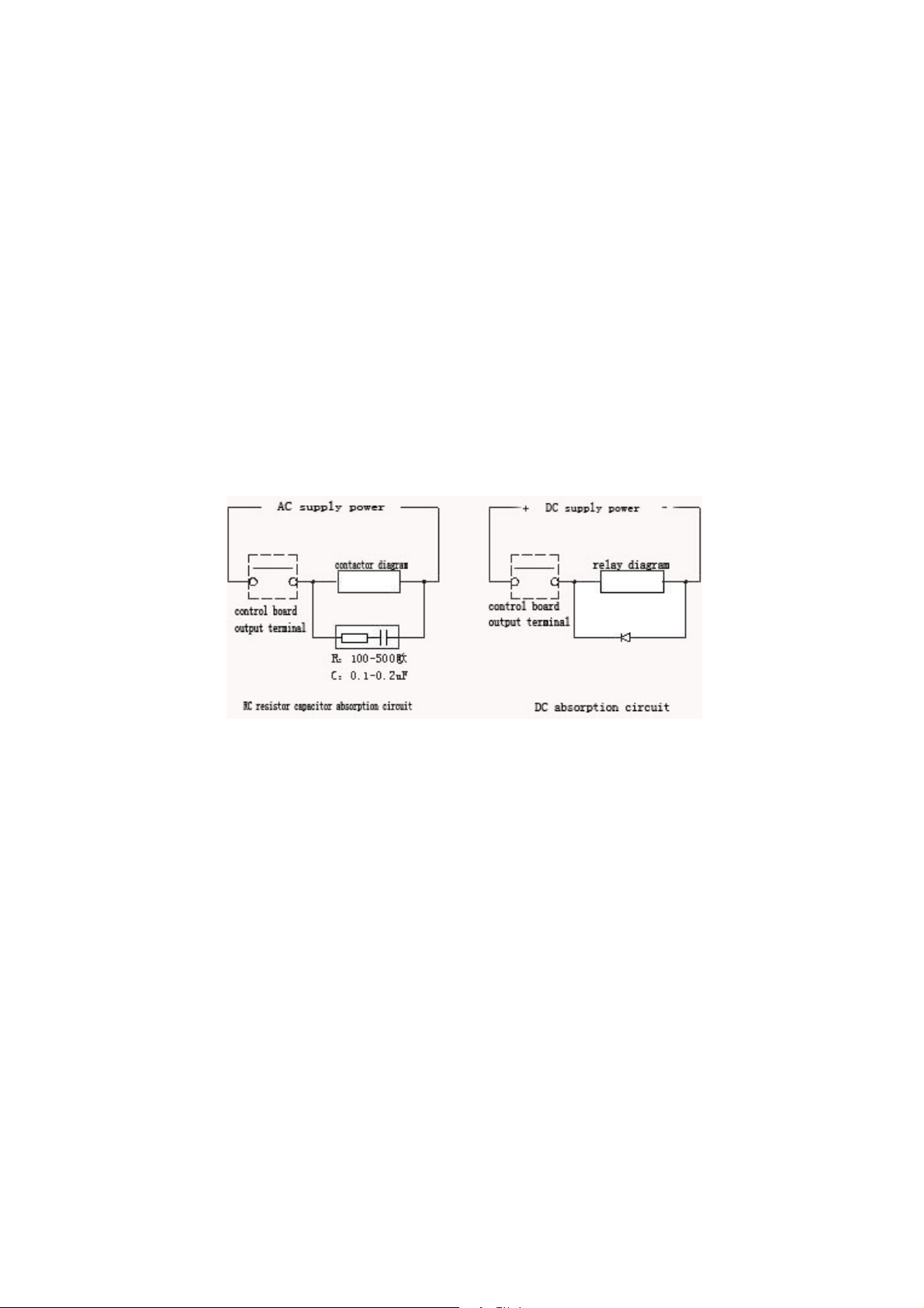
18.If the frequency inverter output terminals drive inductive loads, such
as electromagnetic relays, contactors, etc., surge voltage absorption
circuit should be added, such as RC absorption circuit(be careful that
the leakage current should be lower than the control electromagnetic
relays or contactor' hold current),pressure-sensitive resistance or
freewheel diode(be used in DC electromagnetism circuit, but the polarity
of the freewheel must be paid attention to).The absorption circuit
components must be as close to the relays or winding of the contactor
as possible; Shown as below:
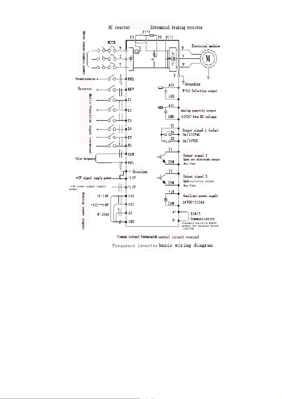
4.2 Basic wiring diagram
The following diagram includs two parts:the main circuit and control
circuit.
25
26
 Loading...