

Veichi SI23-D3-2R2G, SI23-D3-R75G, SI23-D3-1R5G, SI23-D3-004G, SI23-D5-R75G User Manual
...
SI23 Solar Pump Inverter Manual
1
Chapter 1 Safety Requirement and Cautions
To ensure safety of your health, equipment and property, please read this chapter carefully before using the frequency inverter
and act in compliance with the instructions when installing,ebugging, running and overhauling the frequency inverter.
1.1 Safety Definition
Danger: it will cause danger of serious injuries and even death while operating against the rules.
Caution: it will cause danger of light injuries or equipment destruction while operating against the rules.
Note: some information is useful while operating and use frequency inverter.
1.2 Safety Requirements and Cautions
●Before Installation
Danger
1. Only qualified personnel can operate the equipment. Before operating, be sure to carefully read the manual about safety,
installation, operation and maintenance. The safe operation depends on the proper processes of choosing models,
carrying, installation, operation and maintenance.
Danger
1. Don’t use the damaged or incomplete frequency inverters; Otherwise, there is risk of injury.
●Installation
Danger
1. Please install the frequency inverter on metal or other nonflammable material, and keep it away from the combustible
material. Otherwise there is danger of fire;
2. No unauthorized modification to the frequency inverter; Otherwise there is danger of damaged.
3. Normal frequency inverter, which is not explosion-proof, can not be installed where with explosive gas or dust; Otherwise
there is danger of explosion.
Attention
1. When two frequency inverters are installed in the same control cabinet, pleas pay attention to the installing place to
guarantee the effective heat dissipation.
2. When carrying the frequency inverter, ease support its bottom.
●Wiring
Danger
1. Wire is connected only when the main circuit is cut off, otherwise there is a danger of shock.
2. Wire is connected by professional person only. Otherwise there is a danger of shock.
3. Earth must be reliable. Otherwise there is a danger of shock.
4. AC power supply should not be connected with output ports U, V, W, otherwise there is a danger of damage to frequency

SI23 Solar Pump Inverter Manual
2
inverter.
5. No drop of bolt, spacer, metal stick, conducting wire or other things into the inner of frequency inverter; Otherwise there is
a danger of fire or damage to frequency inverter.
Attention
1. If the damage to frequency inverter or other equipment is caused by improper wiring and utilization or unauthorized
alteration, the user should shoulder all responsibilities.
2. Please make sure all wirings meet EMC requirement and satisfy safety standard in the local area; Please refer to
recommendations in this manual or national standards of wire diameter to avoid accidents.
3. Static electricity on human body would seriously damage internal MOS transistor, etc. No touch the printed circuit boards,
IGBT or other internal devices without anti-static measure, otherwise it will cause the malfunction of frequency inverter.
4. Please don't connect phase shifter capacitance or LC/RC noise filter to the output circuit of frequency inverter; Otherwise it
will damage the frequency inverter.
5. Please don't connect the magnetic switch or magnetic contactor to the output circuit of frequency inverter; When frequency
inverter is in the operation with load, magnetic switch or magnetic contactor can make inverter over-current protection
function act. It will damage frequency inverter seriously.
6. Please don't disassemble the panel cover, it only needs to disassemble the terminal cover when wiring.
7. It is forbidden to do any pressure test on frequency inverter, otherwise it will damage the frequency inverter.
●Before Electrification
Danger
1. Please make sure that voltage grade of power supply is consistent with frequency inverter's voltage and then check
whether the wiring is correct and firm, and whether there is short circuit in peripheral equipment's circuit. Otherwise it will
damage frequency inverter and other equipment.
2. Before the frequency inverter is connected to the input power supply, make sure that the cover has been well fixed.
Otherwise it will cause electric shock.
3. For the frequency inverters whose storage time is over 1 year, when electrification, the voltage should be raised by booster
from low to high. Otherwise it will damage the frequency inverter.
Attention
1. Check if all periphery fittings are wired properly according to the handbook; Otherwise it will cause accidents.
●After Electrification
Danger
1. After electrified, it is forbidden to open the cover, make wiring, and check up; Otherwise, it will cause the danger of electric
shock.
2. After electrified, it is forbidden to contact internal wiring board and its parts. Otherwise it will cause the danger of electric
shock.
3. Do not operate or touch frequency inverter with wet hand. Otherwise there is danger of damage to frequency inverter and
electric shock.

SI23 Solar Pump Inverter Manual
3
Attention
1. Please set the parameter of frequency inverter cautiously; Otherwise it will damage equipment.
●Operation
Danger
1. Before running, please check and confirm the application range of the machine and equipment once more; Otherwise it
will cause accidents.
2. Please don't touch the cooling fan and braking resistance to check the temperature; Otherwise there is a danger of
getting burn.
3. Unprofessional workers are banned to check the signals in the running stage; Otherwise it will cause injuries and
damage the equipment.
Attention
1. Please don't turn off the equipment by switching off power; Please cut off the power supply after the electric machine
stops running; Otherwise it will damage the frequency inverter.
2. Please avoid anything dropping into the equipment when the frequency inverter is running; Otherwise it will cause
electric shock.
●Maintenance
Danger
1. Please don't maintain and repair the equipment with electric; Otherwise it will cause electric shock.
2. Before maintaining and repairing the frequency inverter, please make sure the indicator lights of power supply have
completely turned off; Otherwise it may cause electric shock and damage the frequency inverter.
3. Persons who have not passed specialized train are not allowed to conduct the frequency inverter maintenance;
Otherwise it may cause electric shock and damage the frequency inverter.
1.3 Cautions in Using
1. In application of this series frequency inverter, you have to confirm all machine insulation to prevent damage to the
equipment. Moreover, when the motor working in tough environment, please periodic inspect the electrical insulation to
ensure the safety of the system work.
2. If the motor adapter is not consistent with frequency inverter's rating current (The rating current of the motor is far smaller
than that of frequency inverter), please adjust the protective value to ensure safe running.
3. In occasions such as load raises, usually there is negative torque and frequency inverter breaks off for over-current or
over-voltage. In this case, you should consider choosing the matching brake unit.
4. Frequency inverter, in a certain output frequency range, can meet the mechanical resonance of the load equipment. To
avoid it, you can set up jumping frequency.
5. As output voltage of the inverter is pulse-wave type, if there is capacity which can improve power factor or
pressure-sensitive resistance which used for thunder-proof in the voltage output side, the frequency inverter will break off
or its parts will be damaged, so it is necessary to dismantle them. Moreover, it is proposed not install switch parts like air
switch and contactor (if it is necessary to install switch on output side, please make sure the output electricity of frequency
SI23 Solar Pump Inverter Manual
4
inverter is zero when the switch is working)
6. At over 1,000 meters altitude, the inverter’s heat dissipation function worsened due to the thin air, it is necessary to use
less.
7. The inverter output voltage is pulse wave type. If using digital multi-meter measurement, deviation of the reading will be
great. And the deviation is different by using different type of digital multi-meter. Under normal circumstances, while RMS
380V, digital multi-meter reading is around 450V.
8. Solar panel can be connected in the series or parallel. For rated voltage 380V controller, we suggest working voltage
between 480V and 560V while MPPT. What means the solar panel open circuit voltage should be between 600V and
700V.
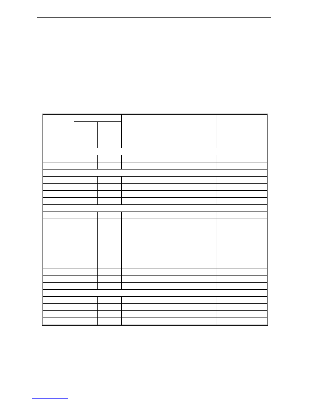
1.4 Technical Specification
Solar pump
inverter
power(KW)
Pump
Max solar
power
input
(KW)
Max DC
input
voltage V
Recommend
Voc voltage (V)
Rated
output
current
(A)
Output
frequency
(Hz)
Rated
power
(KW)
Rated
voltage
(V)
SI23-D1 series, DC60-400VDC input, 3 phase 110-230VAC output
0.75 0.75 110 1.0 400 175~380 7A 0-600
1.5 1.5 110 1.95 400 175~380 10A 0-600
SI23-D3 series,DC150V-450V input, 3 phase 220-240VAC output
0.75 0.75 220 1.0 450 360~430 4A 0-600
1.5 1.5 220 1.95 450 360~430 7A 0-600
2.2 2.2 220 2.86 450 360~430 10A 0-600
4 4 220 5.4 450 360~430 16A 0-600
SI23-D5 series,DC250V to 780VDC input, 3 phase 380-460VAC output
0.75 0.75 380 1.0 780 620~750 3.0 0-600
1.5 1.5 380 2.2 780 620~750 4.0 0-600
2.2 2.2 380 3.3 780 620~750 6.0 0-600
4 4 380 5.6 780 620~750 10 0-600
5.5 5.5 380 8 780 620~750 13 0-600
7.5 7.5 380 10 780 620~750 17 0-600
11 11 380 14.3 780 620~750 25 0-600
15 15 380 19.5 780 620~750 32 0-600
18.5 18.5 380 23.4 780 620~750 38 0-600
22 22 380 28.6 780 620~750 45 0-600
30 30 380 39 780 620~750 60 0-600
SI23-T3 series,DC350V to 780VDC input,3phase 380-440VAC output
37 37 380 48.1 780 620~750 75 0-600
45 45 380 58.5 780 620~750 90 0-600
55 55 380 71.5 780 620~750 110 0-600
75 75 380 97.5 780 620~750 150 0-600
1.5 Cautions in Disposal
When you dispose frequency inverter, please pay attention to:
1. Electrolytic capacitor: the electrolytic capacitor of main circuit or the printing plate may explode when they are burned.
2. Plastic: plastic incineration may generate toxic gases.
3. Dispose method: please dispose as industrial waste.
SI23 Solar Pump Inverter Manual
5
Chapter 2 Installation and Wiring
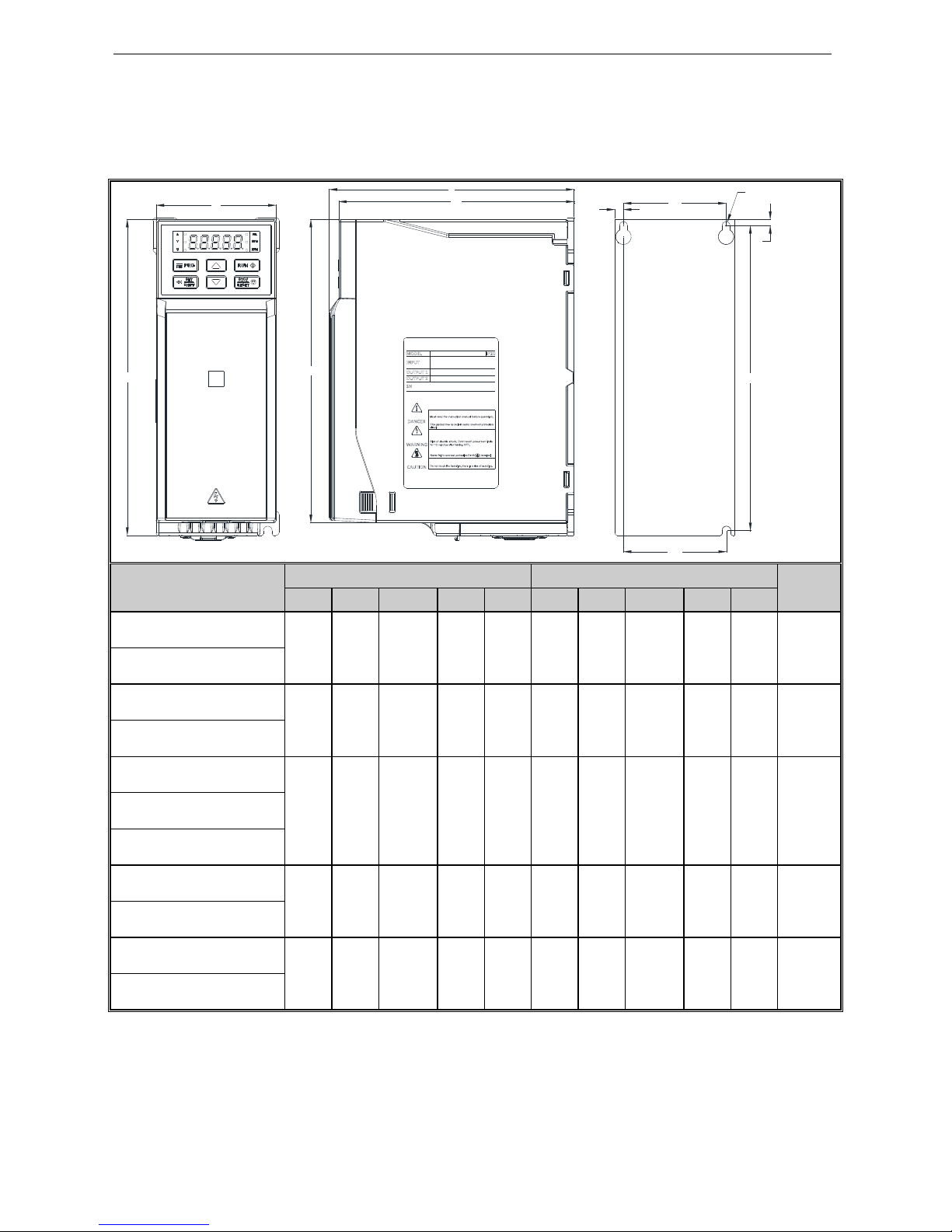
2.1 Dimension of Inverter
Overall Dimension of Inverter (Plastic)
W
D
D1
H
W1
W2
A
B
H2
Installation Diameter
H1
MODEL
Overall Dimension(mm) Installation Dimension(mm)
Apertu
re
W H H1 D D1 W1 W2
H2 A B
SI23-D3-R75G
76 200 192 155 149 65 65 193 5.5 4 ф3-M4
SI23-D3-1R5G
SI23-D3-2R2G
100 242
231 155 149 84
86.
5
231.5
8 5.5 ф3-M4
SI23-D3-004G
SI23-D5-R75G
76 200 192 155 149 65 65 193 5.5 4 ф3-M4
SI23-D5-1R5G
SI23-D5-2R2G
SI23-D5-004G
100 242
231 155 149 84
86.
5
231.5
8 5.5 ф3-M4
SI23-D5-5R5G
SI23-D5-7R5G
116 320 307.5 175 169 98 100 307.5
9 6 ф3-M5
SI23-D5-011G
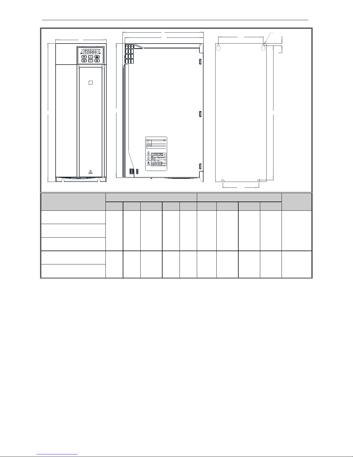
SI23 Solar Pump Inverter Manual
6
W
H
H1
D
D1
W1
W2
B
H2
Installation Diameter
MODEL
Overall Dimension(mm) Installation Dimension(mm)
Aperture
W H H1 D D1 W1 W2 H2 B
SI23-D5-015G
142 383
372 225 219 125 100 372 6 ф4-M5 SI23-D5-018G
SI23-D5-022G
SI23-D5-030G
172 430
/ 255 219 150 150 416.5
7.5 ф4-M5
SI23-T3-037G
SI23 Solar Pump Inverter Manual
7
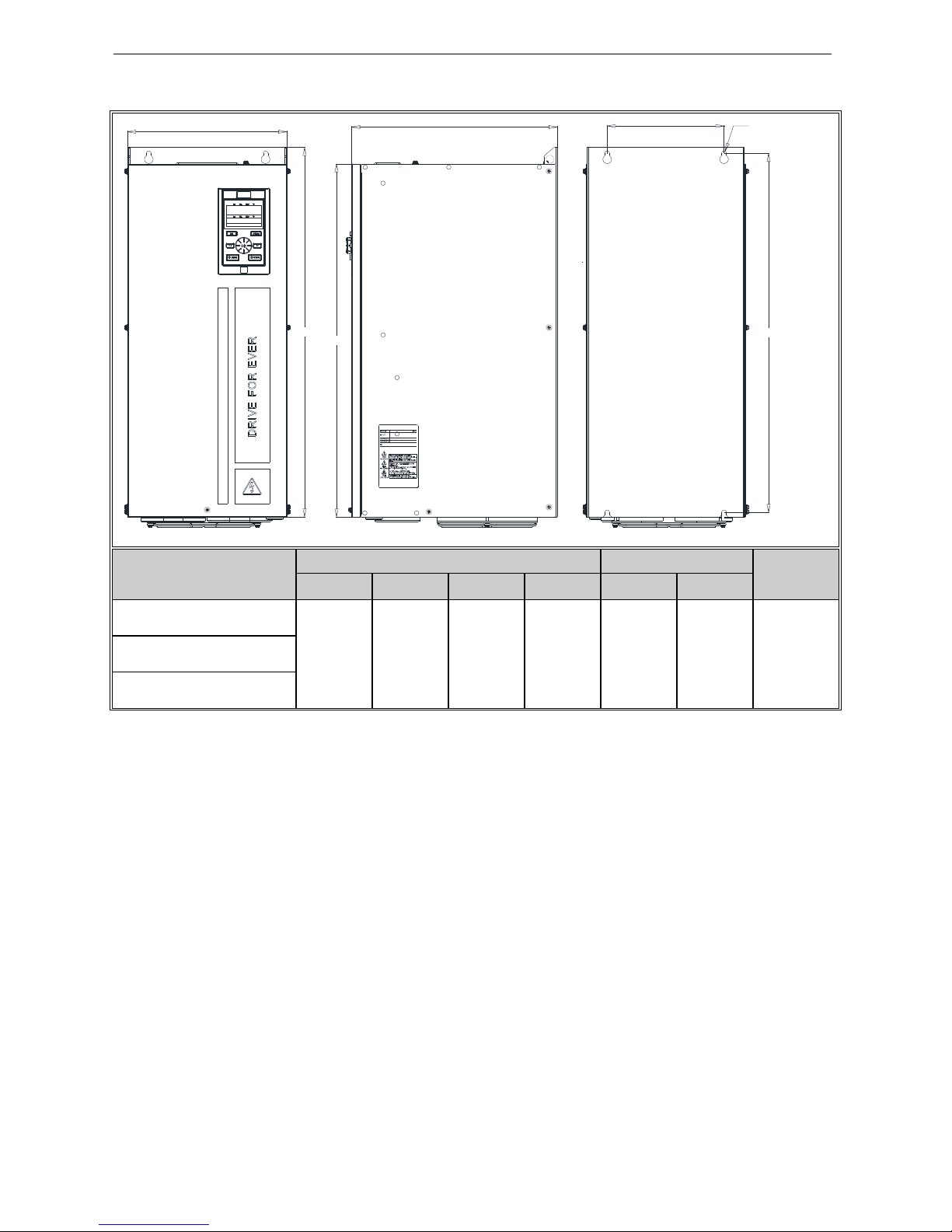
Overall Dimension of Inverter (Steel)
W
H
D
H1
W1
H2
Installation Diameter
MODEL
Overall Dimension(mm)
Installation
Aperture
W H H1 D W1 H2
SI23-T3-045G
240 560 535 310 176 544 ф4-M6 SI23-T3-055G
SI23-T3-075G
SI23 Solar Pump Inverter Manual
8
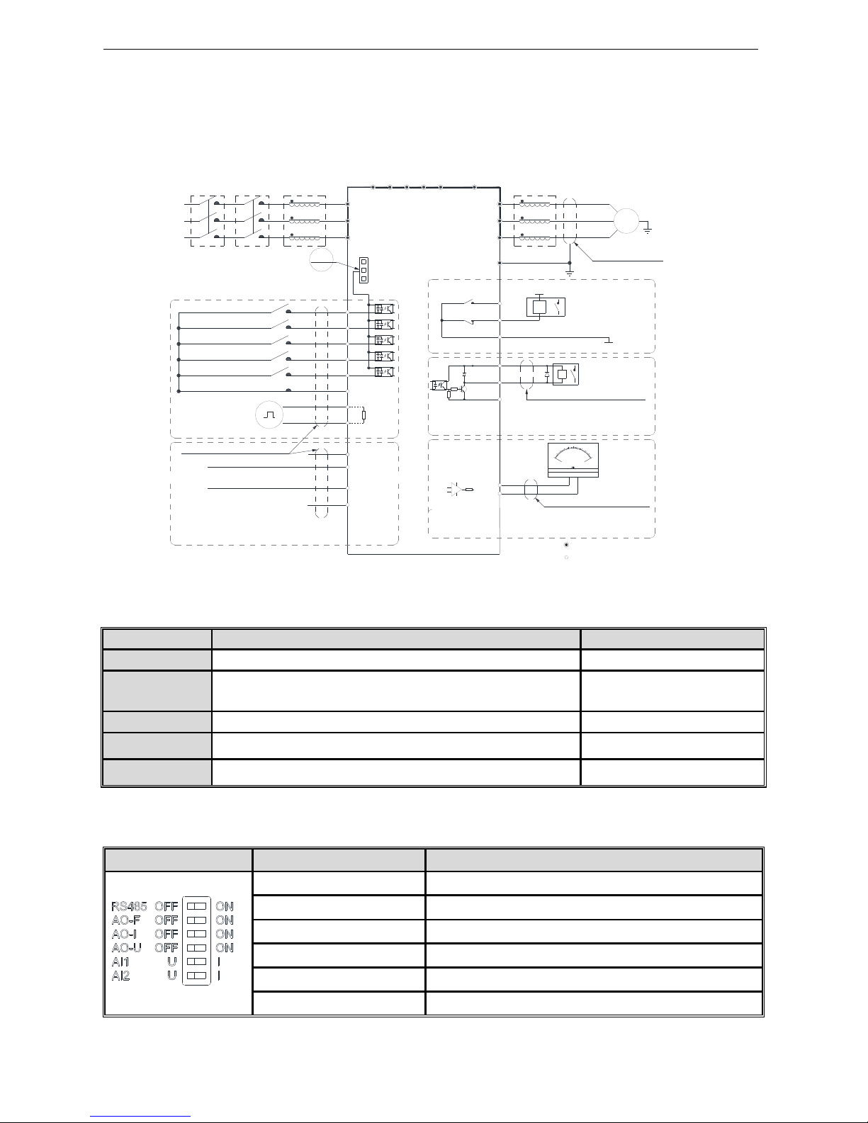
2.2 Solar Pump Controller Wiring
●
Standard Connection Diagram
Note2
Note:Function description in brackets is
factory default
Analog monitoring
signal output
TA
TB
TC
+24V
Y
Shielded cable (the
end close to VFD
grounding)
_
mA
20
10
0
-
+
V
W
U
M
~
Shielded cable or armoured cable
(the end close to VFD grounding)
E
(The grounding resistance
is less than 10 ohms)
W
V
U
Output Rector
P1
+
( )
+10V
Frequency control input
R
T
S
AC POWER INPUT
GND
AI1
AI2
Shielded cable (the end close to
VFD grounding)
Multi function contact input
(Water full detection reset)
(Water full detection alarm)
(Reverse)
(Forward)
(Free STOP)
COM
X3
X4
X5
X1
X2
PB
( )+(-)
VFD
S
T
R
-
+
GND
A0
Coil
COM
Passive contact
output
AC220V
AC0V
Coil
MAX Output Of Contact:
3A/240VAC
5A/30VDC
1.MAX Output of +24V Port:DC24V/100mA
Note:When output type of AO port as
frequency and Voltage,
Maximum Output:2mA
2.Inner resistance of AI1/AI2 Port
1.MAX Output of +10V port :50mANote:
2.Max Output of Y Port :DC24V/50mA
Note:
represent control circuit terminals.
represent main circuit terminals;
Legend: 1.Symbol
Shielded cable
(the end close
to VFD grounding)
Input Rector
ContactorMCCB
+
( )
PUL
+24V
PLC
COM
Analog Voltage/Current quantity input
A+
B-
RS485 Differential
Communication
120Ω
Open collector(OC)
state output
Analog Voltage/Current quantity input
2.Symbol
DC POWER
INPUT
Note: When connect solar panel, both AC input (R, T) and DC input (+, -) is okay, AC input is prefer.
●
Auxiliary Terminal Output Capacity
Terminal Function Definition Max Output
+10V
10V auxiliary power supply output, constitutes loop with GND.
50mA
A0 Analog monitor output, constitutes loop with GND.
Max output 2mA as frequency,
voltage signal
+24V
24V auxiliary power supply output, constitutes loop with COM.
100mA
Y
Collector open circuit output; can set the action-object by program.
DC24V/50mA
TA/TB/TC Passive connector output; can set the action-object by program. 3A/240VAC
●
Function Specification of Switch Terminals
Switch Terminal Selecting Position Function Specification
RS485 Terminal Resistor RS485 Communication :connect with 120Ω terminal resistor
AO-F Output- frequency 0~100kHz frequency output
AO-I Output- Current 0~20mA current output or 4~20mA current output
AO-U Output- Voltage 0~10V voltage output
AI1 Input- Current/Voltage AI1: Input 0~20mA or 0~10V
AI2 Input- Current/Voltage AI2: Input 0~20mA or 0~10V
SI23 Solar Pump Inverter Manual
9
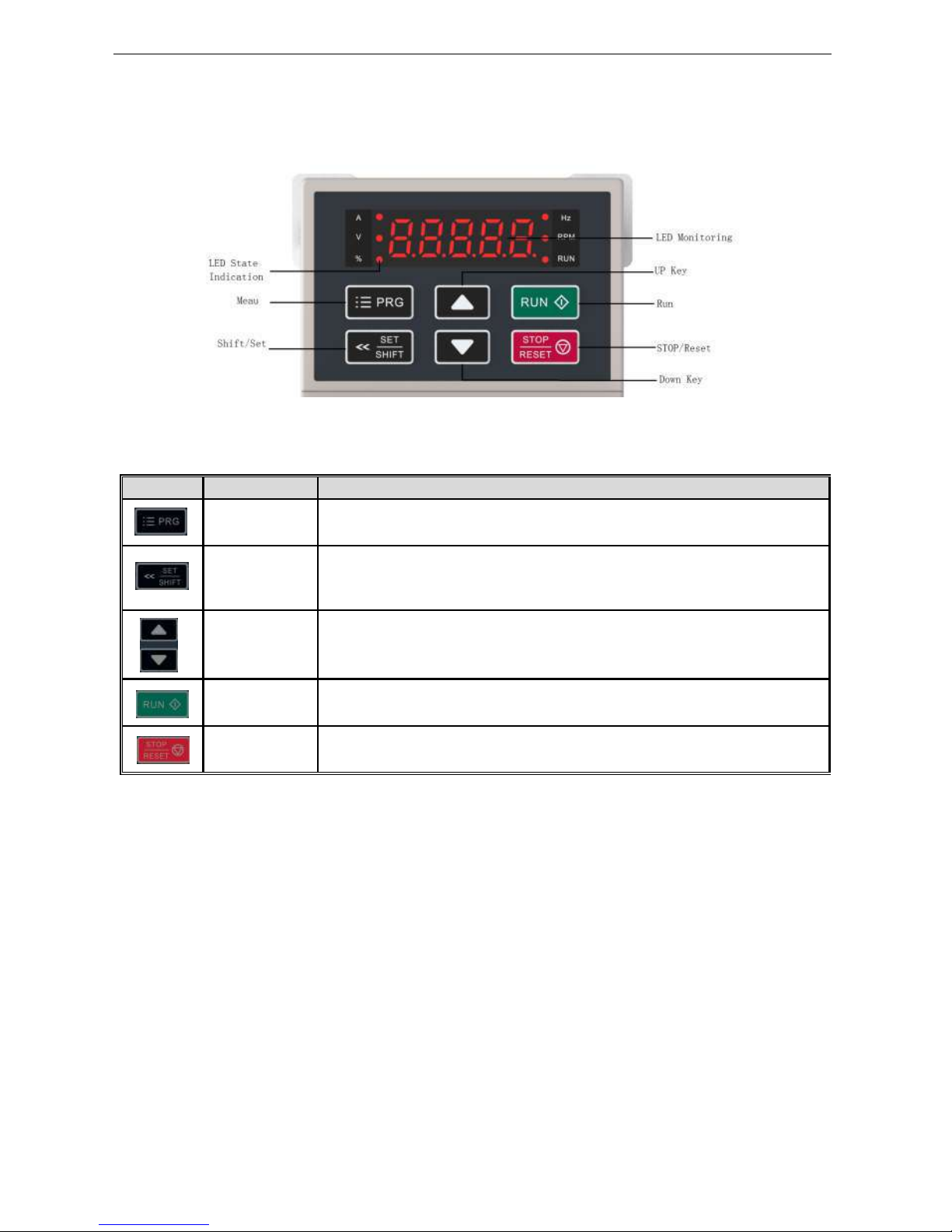
Chapter 3 Keyboard layout and functions specification
●
Keyboard Appearance
●
Key function
Key
Name
Function
Menu key
Enter menu while standby or running. Presses this key to return while modify
parameter. While standby or running, press for 1 sec to enter condition monitoring
Confirm/Shift
key
Press to modify parameter while in menu interface. Press again to confirm after
modifying; Press this key for 1 Sec to shift digit, and long press to cycle. Each digit
flashes three time to shift to next digit.
Up/down key
Select parameter group in menu interface. Modify parameter in modify state. Modify
given frequency, ID given while at standby or monitoring state (While given frequency,
PID are set by keyboard and [F4.09] needs to be set.
Run key
While run/stop is controlled by keyboard, press this key, inverter forward runs, and the
indicator is always on. While reverse, the indicator sparks.
Stop/reset key
Machine stops if press it while run/stop is controlled by keyboard. Its efficiency range is
defined by [F4.08]. Inverter resets if press it in fault state (no reset if fault is not

SI23 Solar Pump Inverter Manual
10
Chapter 4 Fault Diagnosis and Solution
This chapter describes the inverter fault, alerts, and operation of the failure on the inverter, the display information on inverter
and countermeasures.
Fault Information and Description in Detail
Keypad
display
Fault
code
Fault type Possibility reason Troubleshooting
E.LU2
Under voltage at
runs
●Power voltage too low
●DC main contactor don’t
close
●Check input power to solve
● Ask support
E.oU1
Over voltage at
acceleration
●Power voltage fluctuation
over limit
●Too start rotating motor
● Check power grid
● Restart until motor is stop
completely, or set [F1.00] set for 1
or 2
E.oU2
Over voltage
during deceleration
●Deceleration time too small
●The driving load too heavy
●Power voltage fluctuation
over limit
●Prolong deceleration time
●Reduce the load, or select bigger
capacitor drive, or connect braking
unit
● Check input power
E.oU3
Overvoltage at
constant speed
●The input voltage is too
high.
●An external force drives the
motor during deceleration
●Adjust the voltage to
normal range.
●Cancel the external force or install
the braking resistor.
E.oU4
Over voltage at
stop
●Voltage fluctuate above limit ● Check the input voltage
E.oC1
Over current
during
acceleration
●Acceleration time is too
short
●To start rotating motor
●V/F setting not correct or
torque boost setting too big
●Solar drive capacitor is too
small
●Prolong acceleration time
●Restart motor when it on still, or set
F1.00 for 1 or 2.
● Reset V/f curve or torque boost
setting
E.oC2
Over current
during deceleration
●The output circuit is
grounded or short circuited.
●Motor auto-tuning is not
performed.
●The acceleration time is too
short.
●Manual torque boost or V/F
● Eliminate external faults.
●Perform the motor auto tuning.
● Increase the acceleration time.
● Adjust the manual torque boost or
V/F curve.
● Adjust the voltage to
normal range.
 Loading...