

Veichi SI10 User Manual
Version V1 4 in Year 2015: .
Solar Pump Controller Manual
1
Chapter 1: Safety Requirement and Cautions
To ensure safety of your health, equipment and property, please read this chapter carefully
before use the frequency inverter and act in compliance with the instructions while carrying,
installing, debugging, running and overhauling the frequency inverter.
1.1 Safety definition
Danger: it will cause danger of serious injuries and even death while operating against the
rules
Caution: it will cause danger of light injuries or equipment destruction while operating
against the rules
Note: some information is useful while operating and use frequency inverter.
1.2 Safety requirements and cautions
●Before installation
Danger
1. Only qualified personnel can operate the equipment. Before operating, be sure to carefully
read the manual about safety, installation, operation and maintenance. The safe operation
depends on the proper processes of choosing models, carrying, installation, operation and
maintenance.
Danger
1. Don’t use the damaged or incomplete frequency inverters; Otherwise, there is risk of injury.
●Installation
Danger
2. Please install the frequency inverter on metal or other nonflammable material, and keep it
away from the combustible material. Otherwise there is danger of fire;
3. No unauthorized modification to the frequency inverter; Otherwise there is danger of
damaged.
4. Normal frequency inverter, which is not explosion-proof, can not be installed where with
explosive gas or dust; Otherwise there is danger of explosion.
Attention
1. When two frequency inverters are installed in the same control cabinet, pleas pay attention to
the installing place to guarantee the effective heat dissipation.
2. When carrying the frequency inverter,please support its bottom.
Solar Pump Controller Manual
2
●Wiring
Danger
1. Wire is connected only when the main circuit is cut off, otherwise there is a danger of shock.
2. Wire is connected by professional person only. Otherwise there is a danger of shock.
3. Earth must be reliable. Otherwise there is a danger of shock.
4. AC power supply should not be connected with output ports U, V, W, otherwise there is a
danger of damage to frequency inverter.
5. No drop of bolt, spacer, metal stick, conducting wire or other things into the inner of
frequency inverter; Otherwise there is a danger of fire or damage to frequency inverter.
Attention
1. If the damage to frequency inverter or other equipment is caused by improper wiring and
utilization or unauthorized alteration, the user should shoulder all responsibilities.
2. Please make sure all wirings meet EMC requirement and satisfy safety standard in the local
area; Please refer to recommendations in this manual or national standards of wire diameter
to avoid accidents.
3. Static electricity on human body would seriously damage internal MOS transistor, etc. No
touch the printed circuit boards, IGBT or other internal devices without anti-static measure,
otherwise it will cause the malfunction of frequency inverter.
4. Please don't connect phase shifter capacitance or LC/RC noise filter to the output circuit of
frequency inverter; Otherwise it will damage the frequency inverter.
5. Please don't connect the magnetic switch or magnetic contactor to the output circuit of
frequency inverter; When frequency inverter is in the operation with load, magnetic switch or
magnetic contactor can make inverter over-current protection function act. It will damage
frequency inverter seriously.
6. Please don't disassemble the panel cover, it only needs to disassemble the terminal cover
when wiring.
7. It is forbidden to do any pressure test on frequency inverter, otherwise it will damage the
frequency inverter.
●Before electrification
Danger
1. Please make sure that voltage grade of power supply is consistent with frequency inverter's
voltage and then check whether the wiring is correct and firm, and whether there is short
circuit in peripheral equipment's circuit. Otherwise it will damage frequency inverter and other
equipments.
2. Before the frequency inverter is connected to the input power supply, make sure that the
cover has been fixed well. Otherwise it will cause electric shock.
3. For the frequency inverters whose storage time is over 1 year, when electrification, the
Solar Pump Controller Manual
3
voltage should be raised by booster from low to high. Otherwise it will damage the frequency
inverter.
Attention
1. Check all periphery fittings are wired properly according to the handbook; Otherwise it will
cause accidents.
●After electrification
Danger
1. After electrified, it is forbidden to open the cover, make wiring, and check up; Otherwise, it will
cause the danger of electric shock.
2. After electrified, it is forbidden to contact internal wiring board and its parts. Otherwise it will
cause the danger of electric shock.
3. Do not operate or touch frequency inverter with wet hand. Otherwise there is danger of
damage to frequency inverter and electric shock.
Attention
1. Please set the parameter of frequency inverter cautiously; Otherwise it will damage
equipment.
●Operation
Danger
1. Before running, please check and confirm the application range of the machine and
equipments once more; Otherwise it will cause accidents.
2. Please don't touch the cooling fan and braking resistance to check the temperature;
Otherwise there is a danger of getting burn.
3. Unprofessional workers are banned to check the signals in the running stage; Otherwise it
will cause injuries and damage the equipment.
Attention
1. Please don't turn off the equipment by switching off power; Please cut off the power supply
after the electric machine stops running; Otherwise it will damage the frequency inverter.
2. Please avoid anything dropping into the equipment when the frequency inverter is running;
Otherwise it will cause electric shock.
●Maintenance
Danger
1. Please don't maintain and repair the equipment with electric; Otherwise it will cause electric
shock.
2. Before maintaining and repairing the frequency inverter, please make sure the indicator lights
of power supply have completely turned off; Otherwise it may cause electric shock and
damage the frequency inverter.

Solar Pump Controller Manual
4
3. Persons who have not passed specialized train are not allowed to conduct the frequency
inverter maintenance; Otherwise it may cause electric shock and damage the frequency
inverter.
1.3 Cautions in utilization
1. In application of this series frequency inverter, you have to confirm all machine insulation to
prevent damage to the equipment. Moreover, when the motor working in tough environment,
please periodic inspect the electrical insulation to ensure the safety of the system work.
2. If the motor adapter is not consistent with frequency inverter's rating current (The rating current
of the motor is far smaller than that of frequency inverter), please adjust the protective value to
ensure safe running.
3. In occasions such as load raising, usually there is negative torque and frequency inverter
breaks off for over-current or over-voltage. In this case, you should consider to choose the
matching brake unit.
4. Frequency inverter, in a certain output frequency range, can meet the mechanical resonance of
the load equipment. To avoid it, you can set up jumping frequency.
5. As output voltage of the inverter is pulse-wave type, if there is capacity which can improve
power factor or pressure-sensitive resistance which used for thunder-proof in the voltage
output side, the frequency inverter will break off or its parts will be damaged, so it is necessary
to dismantle them. Moreover, it is proposed not install switch parts like air switch and contactor
(if it is necessary to install switch on output side, please make sure the output electricity of
frequency inverter is zero when the switch is working)
6. At over 1,000 meters altitude, the inverter’s heat dissipation function worsened due to the thin
air, it is necessary to use less.
7. The inverter output voltage is pulse wave type. If using digital multimeter measurement,
deviation of the reading will be great. And the deviation is different by using different type of
digital multimeter. Under normal circumstances, while RMS 380V, digital multimeter reading is
around 450V.
8. Solar panel: many panels string or parallel. For rated voltage 380V controller, we suggest
working voltage between 480V to 560V while MPPT. What means the solar panel open circuit
voltage between 600V to 700V.
Solar Pump Controller Manual
5
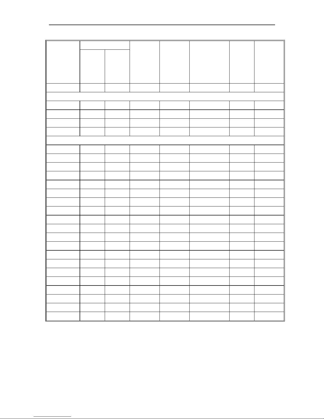
Technical Specification
Solar
pump
controller
power(KW)
Pump motor Max
solar
power
input
(KW)
Max DC
input
voltage V
Recommend
MPPT
voltage (V)
Rated
output
current
(A)
Output
frequenc
y(Hz)
Rated
motor
(KW)
Rated
voltage
(V)
0.75/1.5 0.75/1.5
100-330
1.95 350 100~350 10A 0-60
0.75 0.75 220 1.0 400 220~400 4A 0-60
1.5 1.5 220 1.95 400 220~400 7A 0-60
2.2 2.2 220 2.86 400 220~400 10A 0-60
3.7 3.7 220 4.81 400 220~400 17A 0-60
1.5 1.5 380 2.2 780 480~560 3.7 0-60
2.2 2.2 380 3.3 780 480~560 5.0 0-60
3.7 3.7 380 5 780 480~560 8.5 0-60
5.5 5.5 380 8 780 480~560 13 0-60
7.5 7.5* 380 10 780 480~560 17 0-60
11 11* 380 14.3 780 480~560 25 0-60
15 15 380 19.5 780 480~560 32 0-60
18.5 18.5 380 23.4 780 480~560 38 0-60
22 22 380 28.6 780 480~560 45 0-60
30 30 380 39 780 480~560 60 0-60
37 37 380 48.1 780 480~560 75 0-60
45 45 380 58.5 780 480~560 90 0-60
55 55 380 71.5 780 480~560 110 0-60
75 75 380 97.5 780 480~560 150 0-60
93 93 380 120.9 780 480~560 180 0-60
110 110 380 143 780 480~560 210 0-60
132 132 380 171.6 780 480~560 250 0-60
160 160 380 208 780 480~560 310 0-60
185 185 380 240.5 780 480~560 340 0-60
200 200 380 260 780 480~560 380 0-60
1.4 Cautions in disposal
When you dispose frequency inverter, please pay attention to:
1. Electrolytic capacitor: the electrolytic capacitor of main circuit or the printing plate may explode
when they are burned.
2. Plastic: plastic incineration may generate toxic gases.
3. Dispose method: please dispose as industrial waste.
Solar Pump Controller Manual
6
Chapter 2: Installation
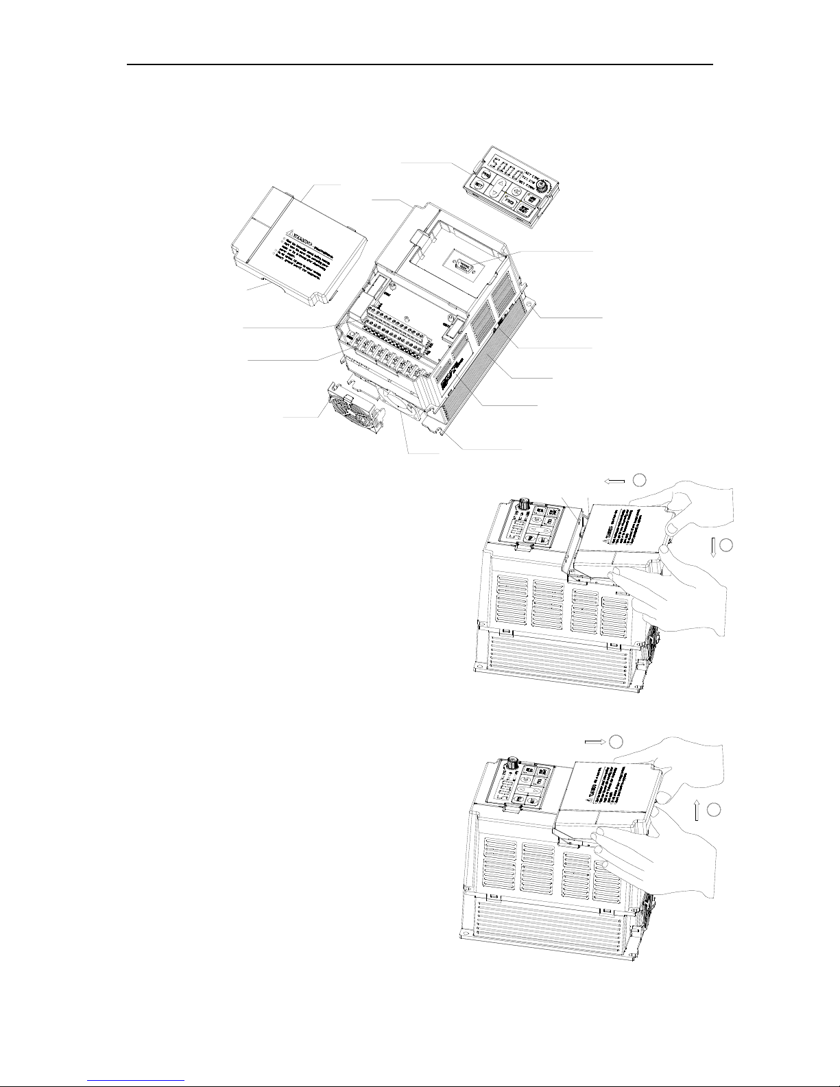
2.1 Products appearance and components titles
operation panel
Tail-hood
pre-cover
keyboard terminal
installation hole
label
air cooler
nameplate
fan cover
support
fan
control loop terminal
main loop terminal
hold hole
2.2
Dismantle and install tail-hood
Installation: First the tail-hood upwardly inclines
around 15 degrees and inserts the top fixed flat
into the fixed hole in the front cover. Then slightly
press the tail-hood downward. While your hear "Ka",
it means that the tail-hood is into the place.
Dismantlement: At the tail of the frequency inverter,
there is a special dismantlement hole design. Put
your fingers into the hole, upwardly pull the cover
with a little force until the buckle between the
tail-hood and the crust tear off, and then removed
tail-hood down.
2
1
tail-hood
stator
tail-hood
install hole
2
1
Solar Pump Controller Manual
7
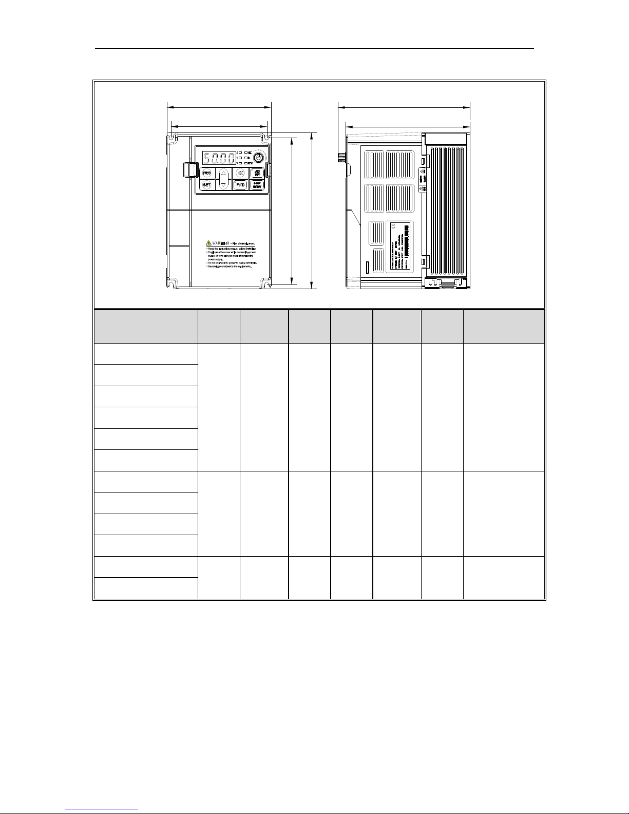
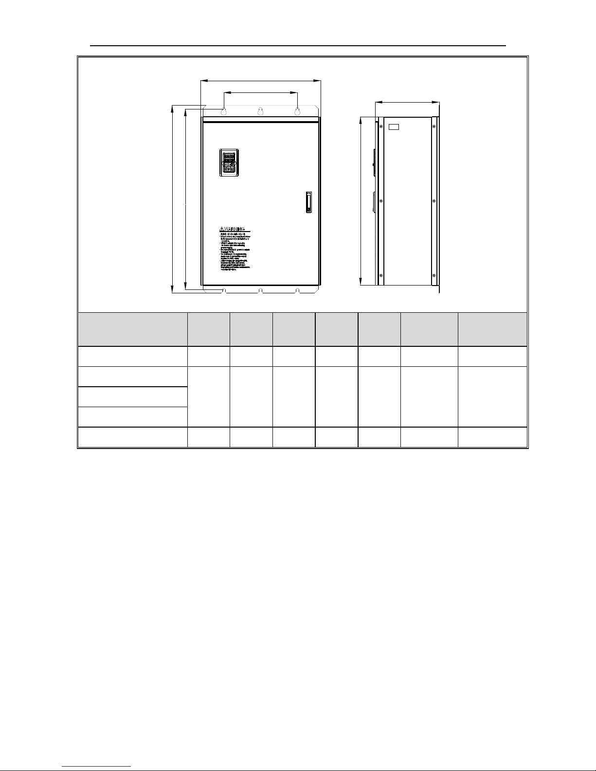
2.3 Installation size(units: mm)
D
D1
H
H1
W
W1
Frequency
inverter
W W1 H H1 D D1
Installation
aperture
SI10-S2-R40G
122 112 182 171 154.5 145 ф5
SI10-S2-R75G
SI10-S2-1R5G
SI10-T3-R75G
SI100-T3-1R5G
SI10-T3-2R2G
SI10-D3-2R2G
159 147.2 246 236 157.5 148 ф5.5
SI10-D3-3R7G
SI10-D5-3R7G
SI10-D5-5R5G
SI10-D5-7R5G
195 179 291 275 167.5 158 ф7
SI10-D5-011G
*D3 stands for 3 phase 220V output with hardware MPPT.
*D5 stands for 3 phase 380V output with hardware MPPT.
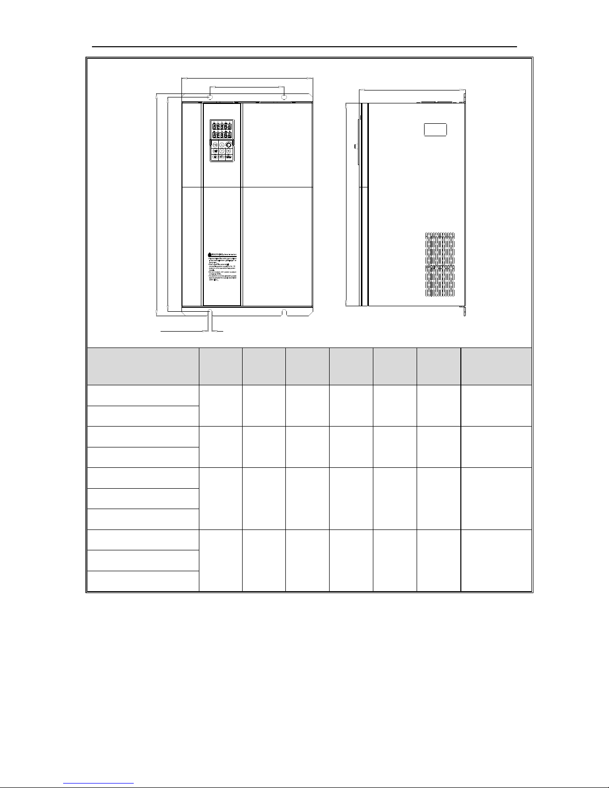
Solar Pump Controller Manual
8
W
W1 D
H
H1
H2
Installation aperture
Frequency inverter
W H D H2 W1 H1
Installation
aperture
SI10-D5-015G
235 345 200 311 160 331.5
ф7
SI10-D5-018G
SI10-D5-022G
255 410 225 370 180 395 Ф7
SI10-D5-030G
SI10-D5-037G
305 570 260 522 180 550 Ф9
SI10-D5-045G
SI10-D5-055G
SI10-D5-075G
380 620 290 564 240 595 ф11
SI10-D5-093G
SI10-D5-110G
Solar Pump Controller Manual
9
H1
H
H2
D
W1
W
Frequency inverter
W H D H2 W1 H1
Installation
aperture
SI10-D5-132G 500 780 340 708 350 755 ф11
SI10-D5-160G
650 1060
400 950 400 1023 ф16
SI10-D5-185G
SI10-D5-200G
SI10-D5-220G 750 1170
400 1050
460 1128 ф18

Solar Pump Controller Manual
10
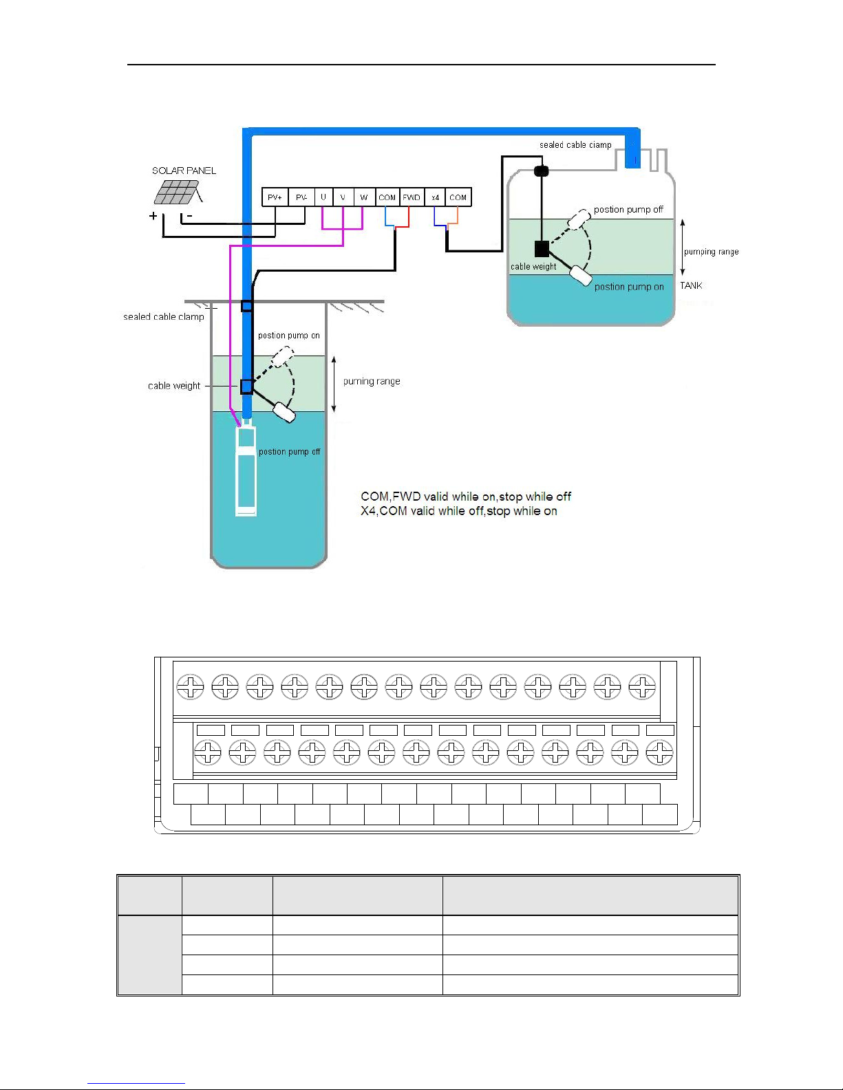
2.4 Solar pump controller wiring
The following diagram includs two parts:the main circuit and control circuit.
stand build-in RS485 module
for machine below 11G
-10V signal supply power
Grounding
Open set electrode output
Output signal 3
Output signal 2
max:50mA
max:50mA
communication
RS485
A+
B-
COM
Y2
Y1
COM
Open set electrode output
GND
A02
F-62 Selection output
Analog input
signal
+10V signal supply power
-10V
GND
Pulse frequency
PUL
REV
REV
X5
Electrical machine
M
V
W
U
Analog quantity output
10VDC-1mA DC voltage
2A/30VDC
3A/250VAC
Auxiliary power
Output signal 1(relay)
24VDC-200mA
PB
N(-)
P1
MCCB
S
T
R
A01
X1
X2
X3
GND
X4
COM
X6
E
FWD
Solar
DC
input
multi-function
input terminal
FWD
TC
TA
TB
+10V
VS2
VS1
+24
AS
COM
main circuit terminal
V
-10V-+10V
4-20mA
cotrol circuit terminal
Earth
Solar Pump Controller Manual
11
Solar pump controller wiring
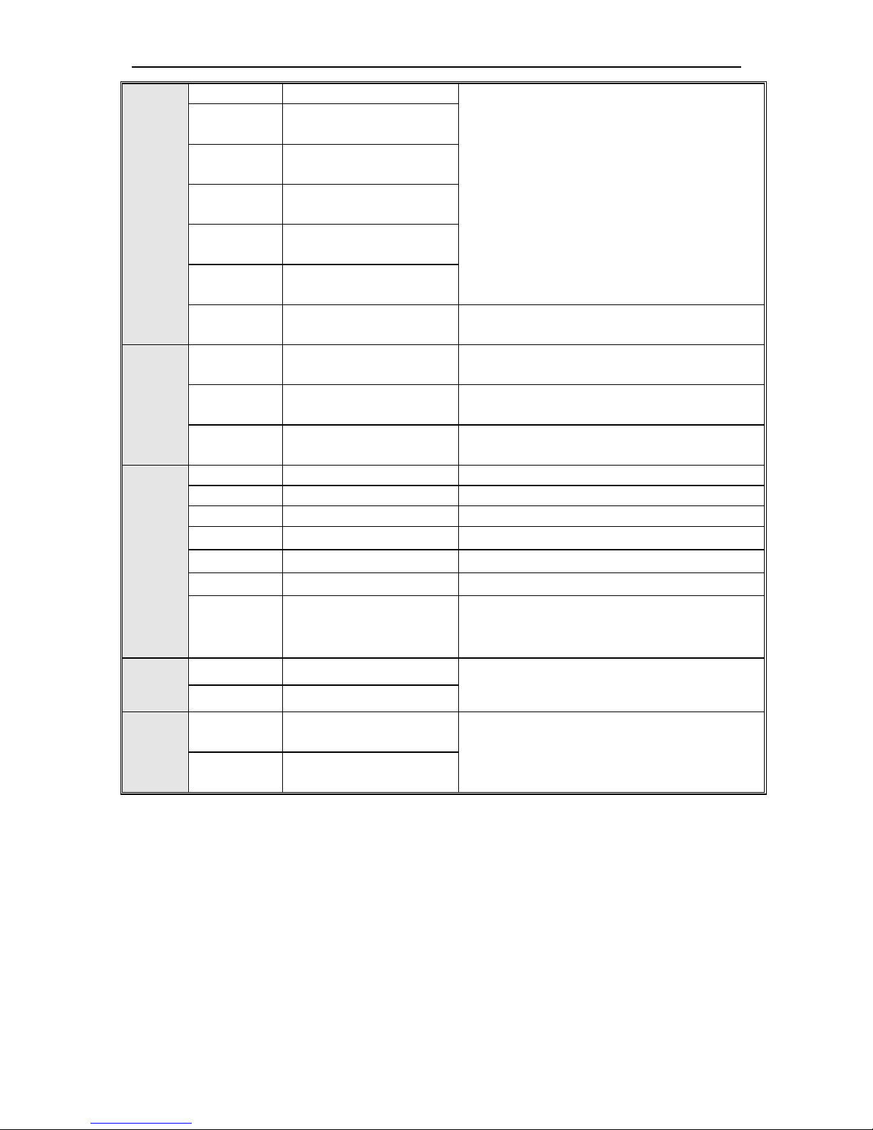
2.5Control circuit terminals
2.5.1 Sequence of control terminals
TC TA
+24
COM REV
TB Y1 Y2
X2
X1
X3
X4
X5
X6
COM
PUL
GND
AO1 AO2
VS1
VS2
AS
+10V
-10V
GND
A+
B-
FWD
2.5.2 Control terminals menu
Categ
ory
Terminal name Function
Control
signal
COM Common terminal
FWD Forward turn command
Short connect with (COM)is workable
REV Reverse turn command
Short connect with (COM)is workable
X1 Multifunction input Short connect with (COM) is workable
Solar Pump Controller Manual
12
terminalsX1
Multifunction input terminals, please refer to
parameters[F-01~F-06]to set the definitions
by program.
X2
Multifunction input
terminalsX2
X3
Multifunction input
terminalsX3
X4
Multifunction input
terminalsX4
X5
Multifunction input
terminalsX5
X6
Multifunction input
terminalsX6
PUL
Pulse frequency input
signal
0KHz-50KHz, Amplitude 8~24V.
Output
signal
TA,TB,TC Output signal 1
(TA-TC)Normally open, (TB-TC) Normally
close (programmable setting motion targets).
Y1 Output signal 2
Open collector output, programmable setting
motion targets. Max output DC24V/50mA.
Y2 Output signal 3
Open collector output, programmable setting
motion targets. Max output DC24V/50mA.
Analog
output
& input
signal
GND
Output common terminal 3
+10V Signal power
Maximum output +10V/50mA.
-10V Signal power
Maximum output -10V/50mA.
VS2 Voltage input signal
(VS2)terminal -10V~10V.
AS Voltage input signal
(AS)terminal 4~20mA .
A01 Analog output signal 1
(A01)terminal 0V~10V.
A02 Output signal 2
0V~10V, 0V~20mA, 4~20mA, frequency
pulse output, By choices of [F-62] and the
terminal jumper J1, J2 and J3.
Auxiliar
y
power
+24 Power anode terminals
Maximum output 24V/200mA.
COM Common terminal
Comm
unicati
on
A+
Communication
Interface
RS485 Communication Interface.
B-
Communication
Interface
 Loading...