

Veichi SD700-5R5A, SD700-1R1A, SD700-1R8A, SD700-3R3A, SD700-7R6A User Manual
...

1
Preface
Thanks for using SD700 series AC servo drive.
VEICHI SD700 series is the general purpose high performance servo drive which
adopts a series of advanced motor control algorithm and 24-bit high precision encoder,
featuring high control precision, fast tracking response, simple and convenient
debugging to meet the function and performance requirements in high-end general
purpose servo applications. Rich application functions such as built-in point control
function, electronic cam, RS485 interface, CANopen interface and 16-bit analog input
can provide high reliability and high cost performance solutions for machine tools,
electronic equipments, robots, textile applications, packaging industry and etc.
This manual is delivered with equipment and only introduces safety precautions,
installation and wiring, function code table, fault diagnoses and processing, monitoring
parameters and etc. For detailed function explanations and application specifications
please refer to SD700 series product instructions or consult VEICHI company. As it is
the basic guide for proper use and safe operation, please carefully read and keep it
and be sure to handle it to end users.
If any problems or special requirements, please feel free to con tact our comp any,
dealers or the customer service center, we will provide dedicated service for you.
This manual is subject to change without notice, thanks for your kind support.

2
Safety Precautions
For safety concerns, please fully understand th e safety requirement s and cautions
before using.
Operational Qualifications
Only professional trained person are allowed to operate the equipment. In addi tion,
operators must undergo professional skills training and be familiar with the equipment
installation, wiring, operation and maintenance, and can correctly respond to vari ous
emergency situations in use.
Safety Guidance
Safety regulations and warning signs come for your security. They are measures to
prevent the operator and machine system from damage. Please carefully read this
manual before using and strictly observe the regulations and warning signs while
operating.
●
Correct transport, store, installation and careful operation and maintenance are
important for servo system safe operation. In transport and store process,
make sure the servo system is free from impact and vibration. It must be stored
where is dry without corrosive air and conducti ve dust, and the temperature
bust be lower than 60
℃。
●
This product carries dangerous voltage and controls driver machine with
potential danger . If you don’t abide by the regulations or requirement s in this
manual, there is danger of body injury even death and machine damage.
●
Do not wire while the power is connected. Otherwise, there is danger of death
for electric shock. Before wiring, inspection, maintenance, please cut off pow er
supply of all related equipments and ensure main DC voltage in safe range.
And operate it after 10 minutes.
●
Power line, motor line and control line must be fastened. The grounding
terminal must be grounded reliably and the grounding resistance is less than
10Ω.
●
Human body static electricity will seriously damage the internal sensitive
devices. Before operation, please follow ESD measures, or there will be
danger of servo system damage.
●
As the output volatge of servo system is pulse weave, if component s such as
capacitors for improving power factor or pressure-sensitive resist ances for
anti-thunder are installed at the output side, please dismantle them or change
to input side.

3
●
No switch components such as breaker and cont actor at the output side (if
necessary, please be sure the output current is 0 while the switch acting).
●
No matter where the fault is, there is danger of serious accident. So there must
be additional external prevent measures or backup device.
●
Only used in application fields as maker stated. No use in equipment s related
to special fields such as emergency, rescuer, shi p, medical treatment, avigation,
nuclear and etc.
●
Maintenance of this product can only be carried out by the comp any or the
authorized professionals, unauthorized modification or using non-approved
parts may lead to product fault s. Any defective devices must be replaced in
time during maintenance.
4
Chapter 1 Installation and wiring
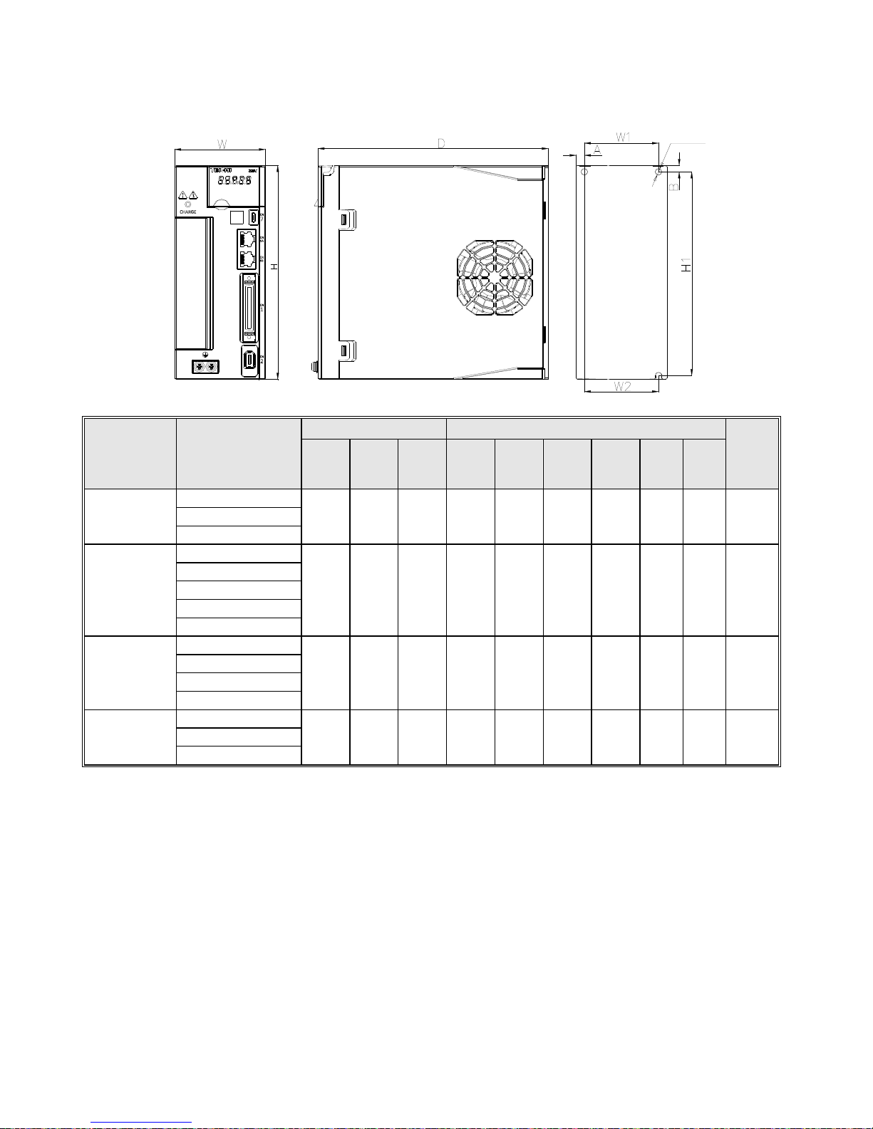
1.1
Installation Dimensions
Dimension
Structure Model
Dimensions(mm
)
Installation dimensions (mm)
Mou
nting
apert
ure
W H D W1 W2 H1 H2 A B
SIZE A
SD700-1R1A-**
45 168 170 \ 20 160 \ 7.5 5 2-M4 SD700-1R8A-**
SD700-3R3A-**
SIZE B
SD700-5R5A-**
71 168 180 58 58 160 \ 6.5 5 3-M4
SD700-7R6A-**
SD700-9R5A-**
SD700-2R5D-**
SD700-3R8D-**
SIZE C
SD700-160A-**
92.5 188 182 82.5 75 180 \ 5 5 3-M4
SD700-6R0D-**
SD700-8R4D-**
SD700-1 10D-**
SIZE D
SD700-170D-**
120 260 210 100 84.5 250 236 \ \ 4-M5 SD700-240D-**
SD700-300D-**
5
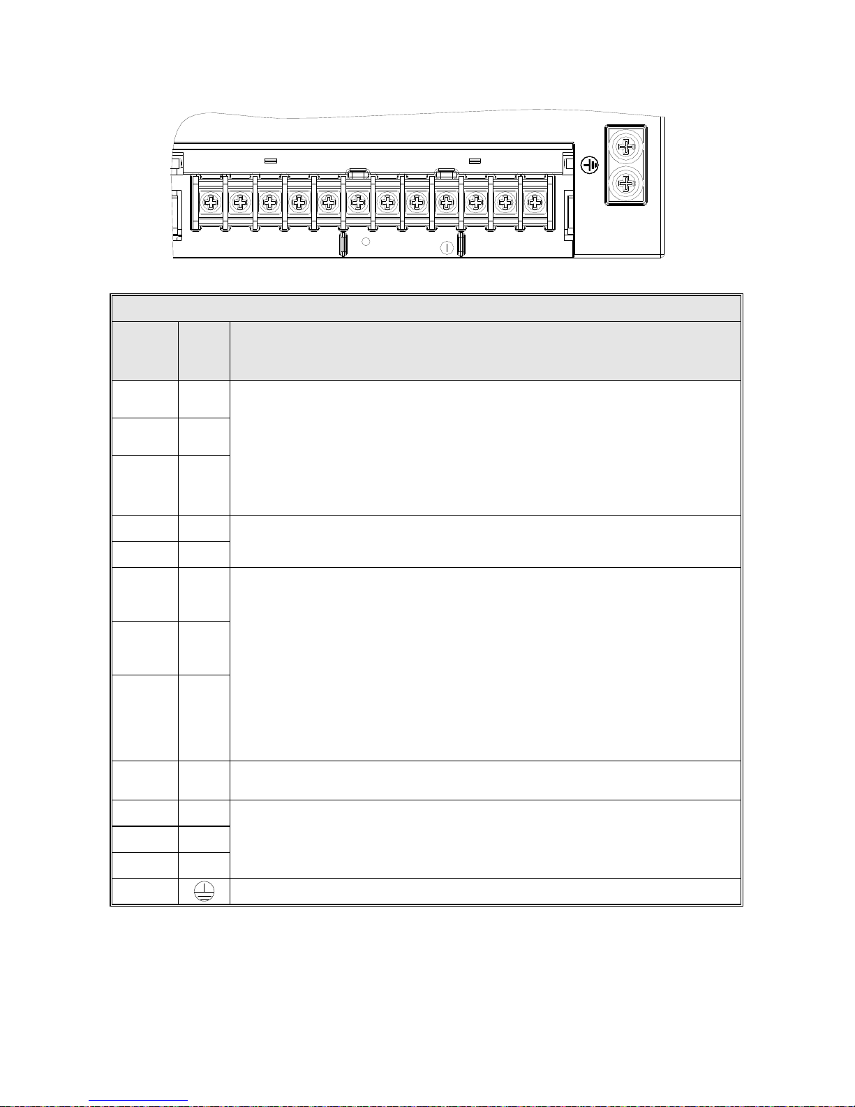
1.2
Main circuit terminal size
L1
L2
L3
L1C
L2C
B1
B2
B3
U
V
W
+
/
Main circuit interface
Pins
numb
er
Sign
nam
e
Function
1 L1
Power input of the main circuit
Please determine whether the input power is 220V or 400V according
to the nameplate
220V models: 200V ~ 240V, -15% ~ +10% 50 / 60Hz
400V models: 380V ~ 440V, -15% ~ +10% 50 / 60Hz
Note: "L3" terminal, SD700-1R1A, 1R8A, 3R3A models are
single-phase inputs without this pin
2 L2
3 L3
4 L1C
Control power input
Power input requirements same with L1, L2, L3
5 L2C
6
B1/
+
Regenerative resistor connection terminal
SD700-1R1A, 1R8A, 3R3A. When regenerative braking capacity is
insufficient, connect an external regenerative resistor between B1 / +
and B2; other models remove short wiring or short connection between
B2 and B3, Connect an external regenerative resistor between B1 / +
and B2, The external regenerative resistor need be purchased
separately.
"B1 / +" terminals can be used for common DC bus positive pow er
supply terminals
Note: "B3" terminal, SD700-1R1A, 1R8A, 3R3A models without this pin
7 B2
8 B3
9 -
"-" terminal can be used for common DC bus negative power supply
terminals
10 U
Connect the U, V, W phase of the motor
11 V
12 W
13
Safe ground
6
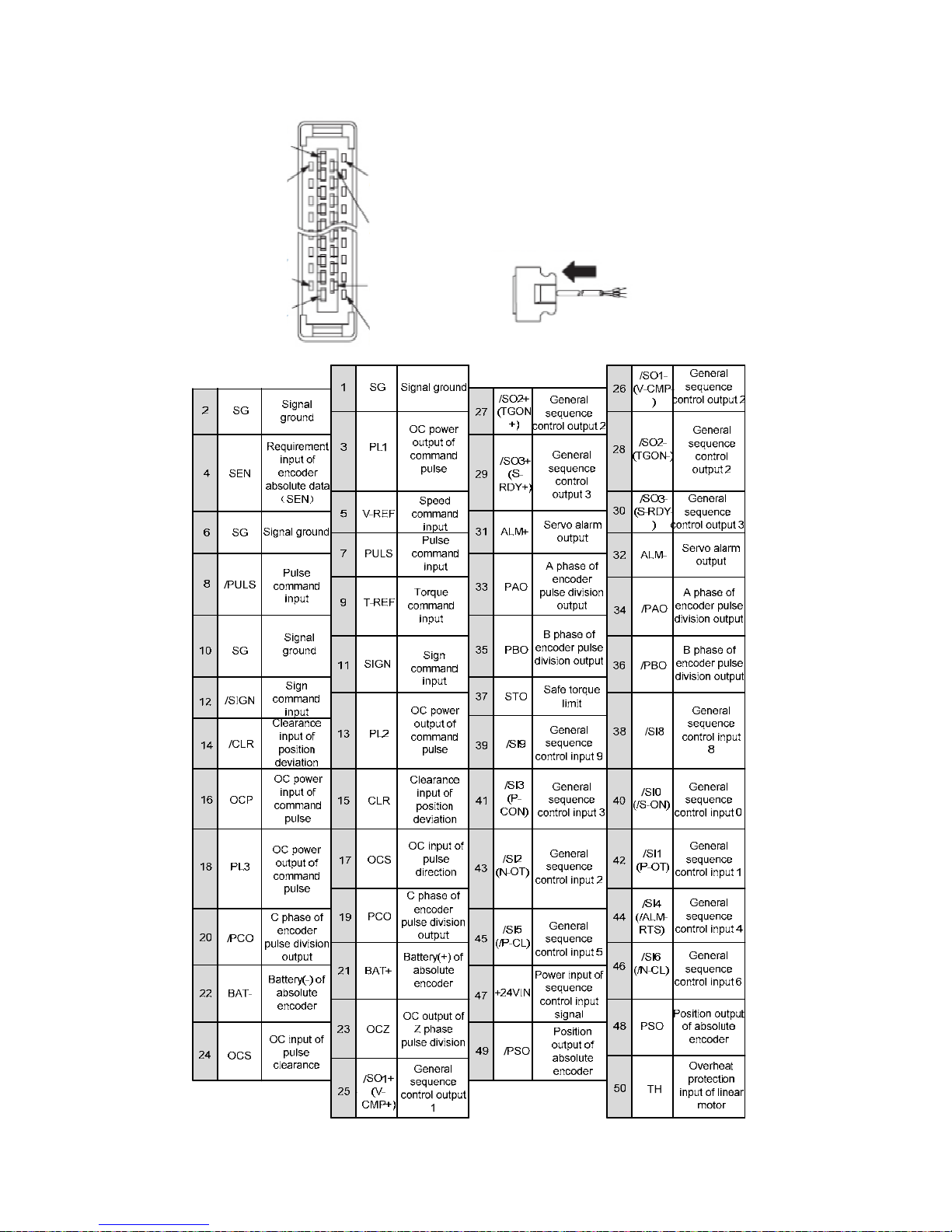
1.3
CN1 Control T erminal
No.1
No.2
No.24
No.25
No.26
No.27
No.49
No.50
The appearance seen from the
arrow direction is shown below.
7
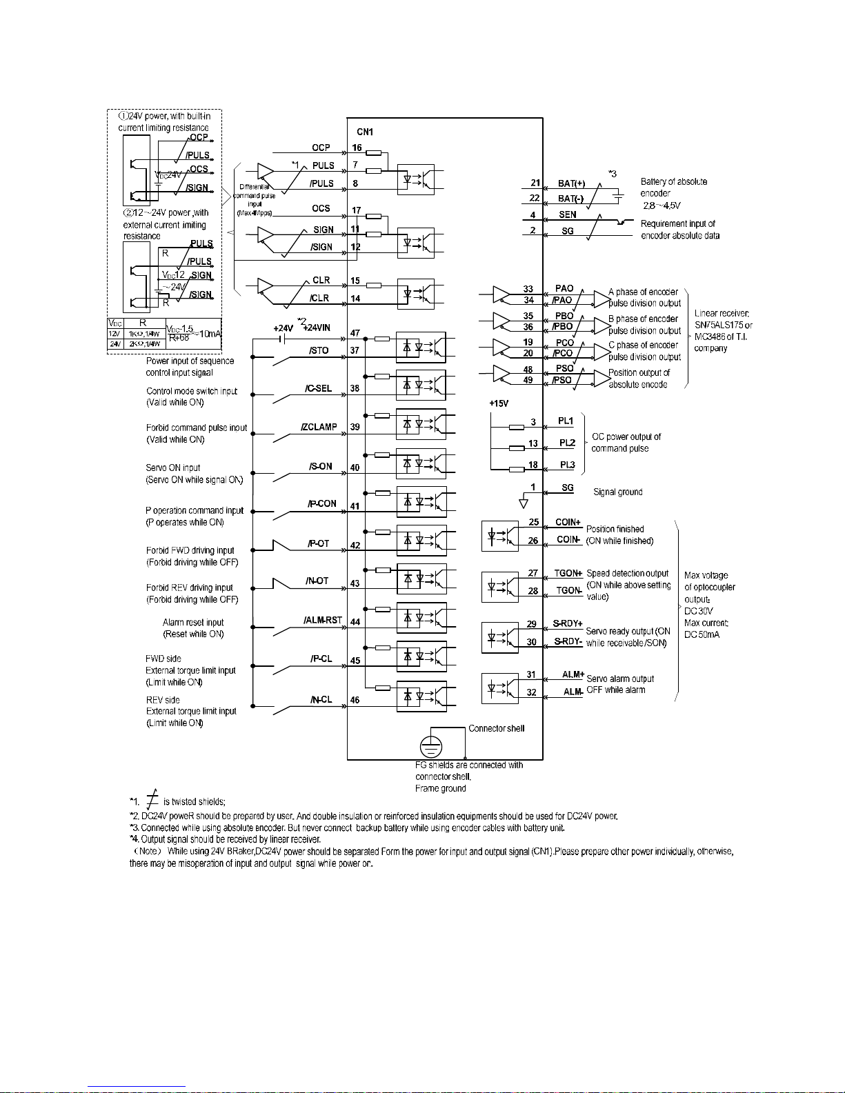
1.4
Position Control Wiring Diagr am
8
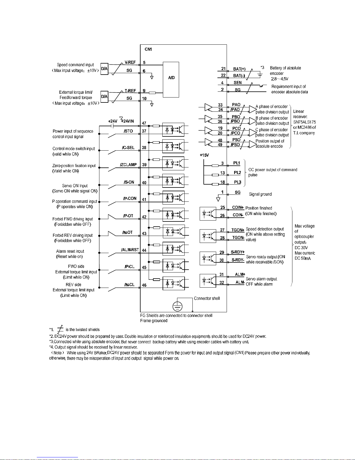
1.5
Speed Control Wiring Dia gram
9
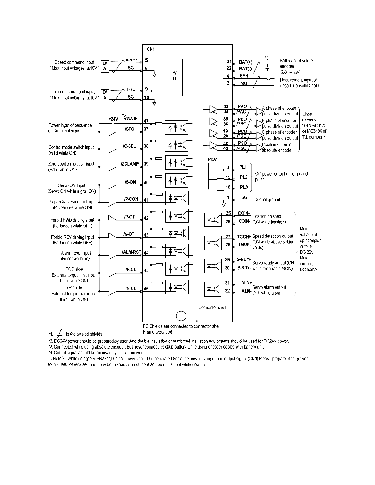
1.6
T orq ue Control Wiring Diagram
 Loading...