

Veichi AC90 User Manual
Manual
AC90 Tension Control Frequency Inverter
Version V1 .1

Version: YEAR2015, V1.1
Shenzhen Veichi Electric Co., Ltd all right reserved. No copy permit. No notify if any modification
More information in compay web: http://www.veichi.com
Shenzhen Veichi Electric CO., LTD
3rdFloor,BlockC,WentaoScienceandTechnologyPark,ShiyanYingrenshi
Community,BaoanDistrict,ShenzhenCity,China.
http: //www.veichi.com
Tel: +86-755-29685610 +86-755-29685611 +86-755-29685612
Fax: +86-755-29685615
Zip: 518108
Mail: veichi@veichi.com

Foreword
Thanks for using AC90 tension control frequency inverter produced by Shenzhen Veichi Electric Co.,Ltd..
AC90 tension control frequency inverter is is a special high-performance vector tension control inverter developed by
our company recently. It adopts advanced torque mode open loop tension control technology. It is not only an
international leader in motor control performance, it also combines tension control industry characteristics, which further
strengthened the product reliability, stability and ease of debugging, can to better meet the demand in the field of
tension control.
This product is to keep constant tension by the output torque control and automatic roll diameter calculation. The
system does not need to install a tension sensor, no need to feedback of the external signal of the current position, or
the tension. It is able to complete the tension control even without need to install speed feedback rotary encoder in most
applications.
To meet the needs of different customers, the product provides two basic control modes. Control modes including:
1: Speed control mode
Inverter controls the speed of the motor by controlling the output frequency. The output torque of the motor is decided
by the load side, but will be limited in the maximum output torque. It is applicable to all types of speed purposes.
2: Torque control mode
The target of the inverter is to control the motor output torque. The motor speed is decided by the load side, but will be
limited in the setting frequency. In this mode, the user can set the tension value, and make tension open-loop control
coming true through the inverter diameter calculation function.
In tension open-loop control, roll diameter calculation is a very important part. Inverter has three roll diameter
calculation methods:
A: Linear speed method.
means linear speed of traction side; means The angular velocity of the rotation of the motor; means
mechanical reduction ratio; means winding roll diameter.
B: Thickness calculation method.
Accumulate the diameter according to the material thickness and cycles of the roll rotation to gain the roll diameter.
C: Time calculation method
Time integral method needs the time from empty roll to full roll, torque for empty roll and torque for full roll. Inverter will
increase torque giving value according to the change of the roll diameter and time.
AC90 tension control inverter can completely replace the torque motors, DC motors, tension controller and be
independent tension control system, which makes the control system more concise, easier to maintain and with better
tension control performance. It is suitable for application to paper, paper processing, printing and dyeing, packaging,
wire and cable, optical fiber cable, adhesive tapes, textile, leather, metal foil processing, fibers, rubber and other
industries.
v
k
r
r
v
k

Contents
Chapter 1 Overview……………………………………………………………………………………... 1
1.1 Safety requirement and cautions……………………………………………………………... 1
1.2 Technical criterion ……………………………………………………………………………… 4
Chapter 2 Before Use………………………………………………………………………………….. 6
2.1 Purchase inspection………………………………………………………………………….. 6
2.2 Nameplate ……………………………………………………………………………………... 6
2.3 Standard models and rated parameters…………………………………………………… 7
Chapter 3 Installation and Wiring……………………………………………………………………. 8
3.1 Safety Precautions………………………………………………………………………….8
3.2 Treatment for inverter after longtime store …………………………………………………9
3.3 Inverter stable running environment………………………………………………………...9
3.4 EMI Protection………………………………………………………………………………... 10
3.5 Machinery installation………………………………………………………………………….13
3.6 Electric installation…………………………………………………………………………….20
Chapter 4 Basic Operation and Trial Run…………………………………………………………..34
4.1 Safety Precautions…………………………………………………………………….……34
4.2 Keyboard layout and functions specification………………………………………………..35
4.3 Basic operation…………………………………………………………………………………37
4.4 Trial run………………………………………………………………………………………...41
Chapter 5 Fault Diagnoses and Processing………………………………………………………..50
5.1 Fault types……………………………………………………………………………………. 50
5.2 Fault information and details ……………………………………………………………... 50
5.3 Fault diagnoses process ……………………………………………………………………54
Chapter 6 Periodic Overhaul and Maintenance…………………………………………………….60
6.1 Safety Precautions…………………………………………………………………………60
6.2 Overhaul……………………………………………………………………………………….60
6.3 Maintenance………………………………………………………………………………...62
Chapter 7 Peripheral Equipments and Options………………………………………………. 65
7.1 Safety Precautions………………………………………………………………………... 65
7.2 Peripheral equipments……………………………………………………………………... 65
7.3 The use of peripheral equipments ………………………………………………………….67
Chapter 8 Quality Guarantee……………………………………………………………………….. 70
8.1 Guarantee time and range…………………………………………………………………..70
8.2 Liability exemption …………………………………………………………………………...70
8.3 Product application …………………………………………………………………………...70
Chapter 9 Function Parameter Specification ............................................................................. 71
9.1 Basic parameters ............................................................................................................. 71
9.2 Operation control parameter ............................................................................................ 80
9.3
Switch quantity terminal parameters ................................................................................ 86
9.4 Analog terminal parameters ............................................................................................ 96
9.5 Keyboard and display parameters ................................................................................. 100

9.6 Motor parameters............................................................................................................. 103
9.7 VC control parameter ....................................................................................................... 105
9.8 V/F control parameters .................................................................................................... 107
9.9 Malfunction and protection parameters ........................................................................... 114
9.10 Machine malfunction code table .................................................................................... 117
9.11 PID parameters .............................................................................................................. 125
9.12 Multi-step, PLC function and swing frequency parameters ........................................... 131
9.13 Communication control function parameters ................................................................. 132
Chapter 10 Appendix .................................................................................................................. 145
10.1 Appendix 1: Function parameter table ............................................................................. 145
10.2 Appendix 2: RS485 communication protocol ................................................................... 179
10.3 Appendix 3: PG card manual ........................................................................................... 186
AC90 TENSION CONTROL FREQUENCY INVERTER MANUAL BASIC OPERATION AND TRIAL RUN
1
Chapter 1 Overview
Thanks for using AC90 tension control frequency inverter produced by Shenzhen Veichi Electric Co.,Ltd..This manual
tells you how to use it perfectly. Please read this manual carefully and fully understand the safety requirement and
cautions before use (installation, wiring, operation, maintain, checking, and etc...).
1.1 Safety requirement and cautions
Pls do totally understand this part before using the inverter.
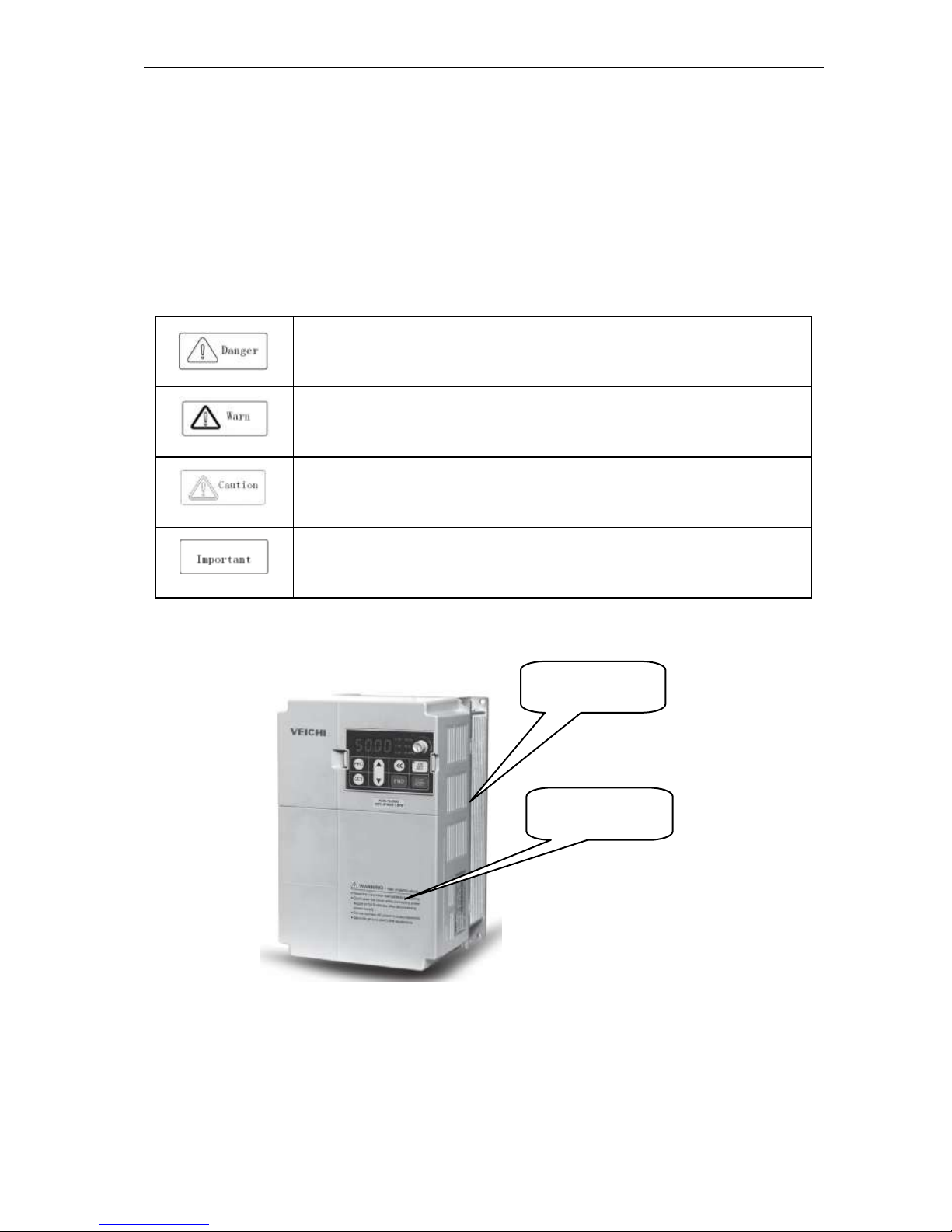
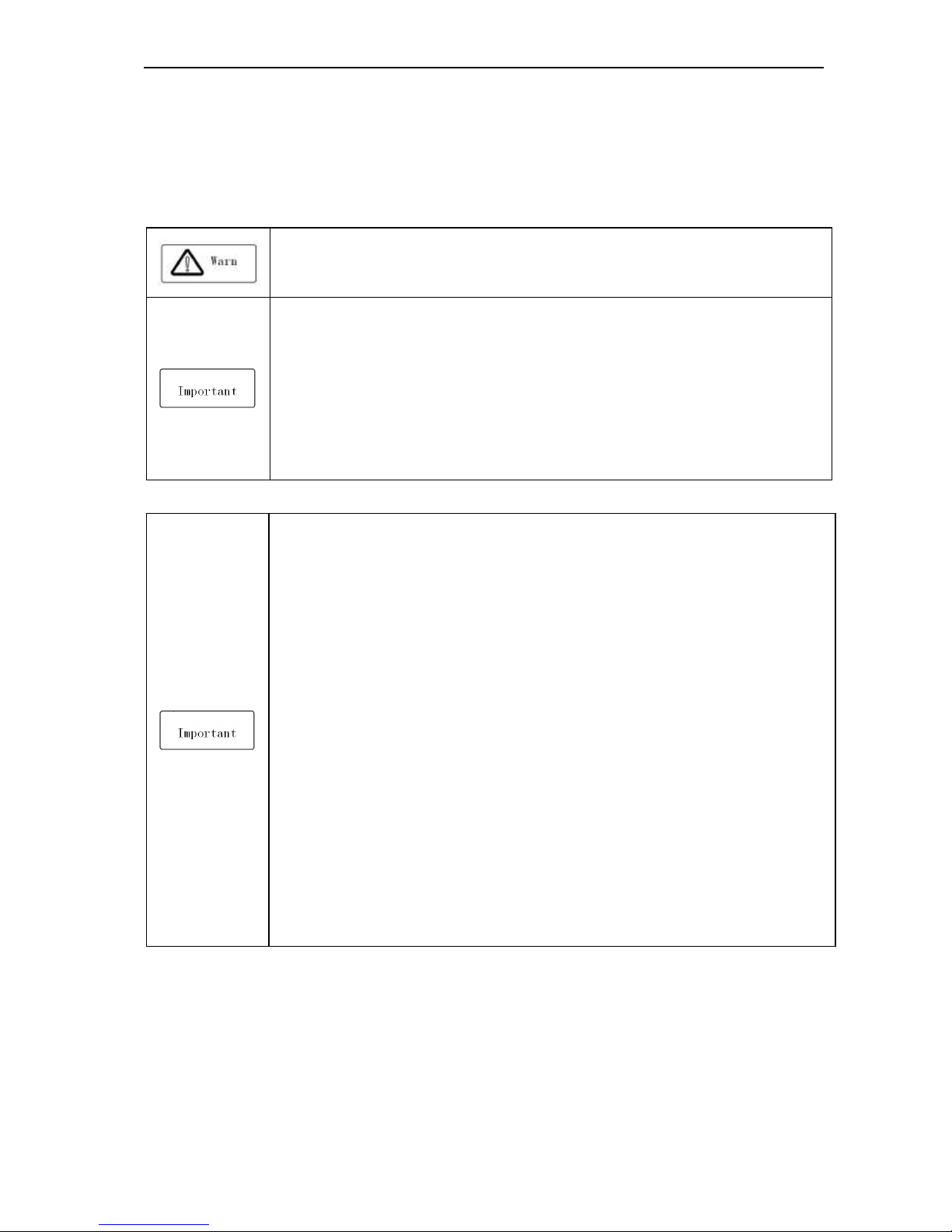
Warning signs and meanings
This manual has used belowing signs that mean there is an important part of security. While observing against the rules,
there is danger of injury even death or machine system damage.
Danger: Wrong operation may cause death or large accident.
Warning: Wrong operation may cause death or large accident.
Caution: Wrong operation may cause minor wound.
Important: Wrong operation may cause the inverter and other machine system damage
Warning signs position
Drawing 1:Warning positions on crust of AC90 series inverter
Warning position 2
Warning position 1
AC90 TENSION CONTROL FREQUENCY INVERTER MANUAL BASIC OPERATION AND TRIAL RUN
2
Operation requirement
Only Professonal trained person are allowed to operate the equipment such as installation, wiring, running, maintain
and etc. “Professonal trained person”in this manual means the workers on this product must experience professional
skill train, must be familiar with installation, wiring, running and maintain and can rightly deal with emergency cases in
use.
Safety guidance
Safety regulations and warning signs come for your security. They are measures to prevent the operator and machine
system from damage. Pls carefylly read this manual before using and strictly observe the refulations and warning signs
while operating. Safety regulations and warning signs are classified into: routine regulation, transport and store
regulation, installation and wiring regulation, running regulation, maintenance regulation, dismantlement and disposal
regulation.
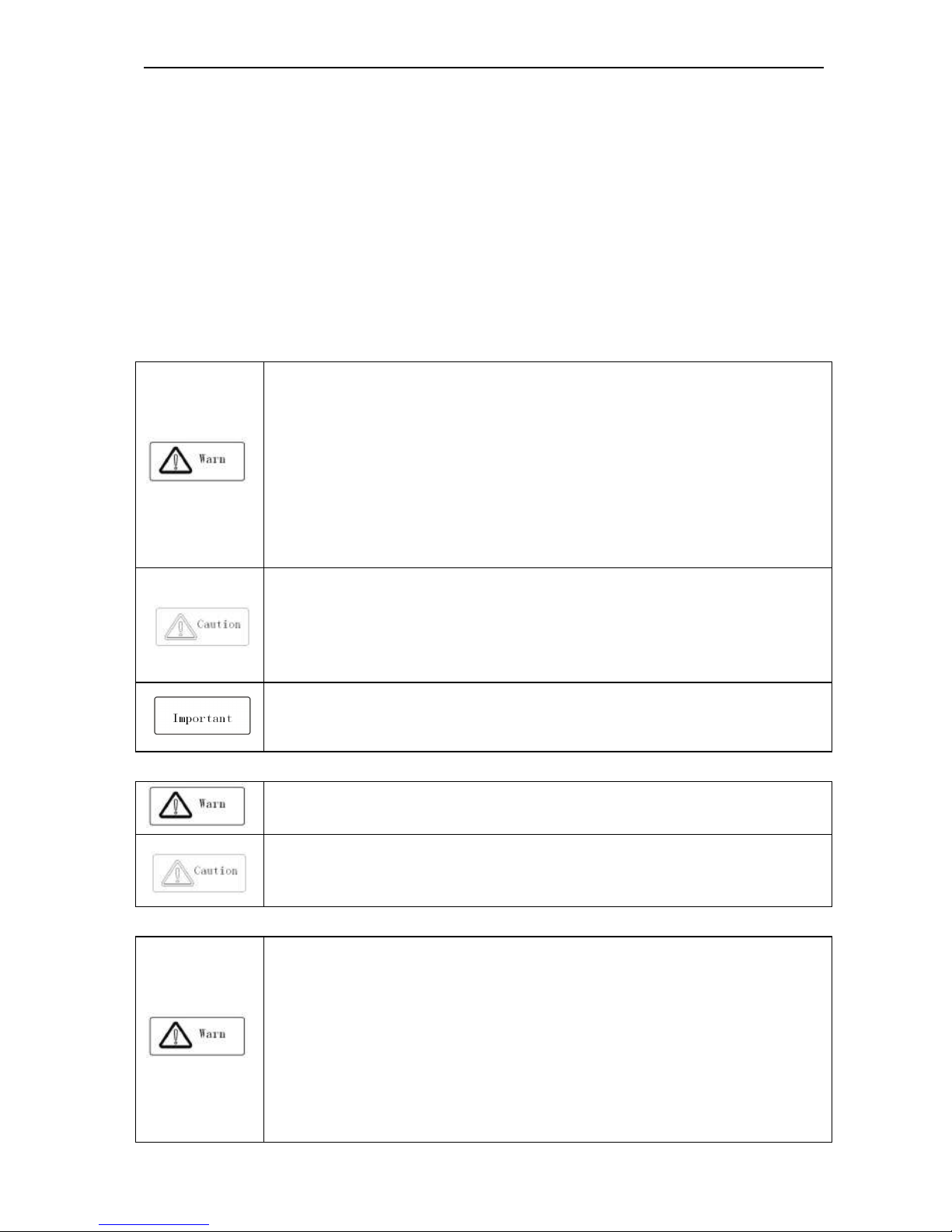
● Routine regulation
● This product carries dangerous voltage and controls driver machine with potential danger. If
you don’t abide by the regulations or requirements in this manual, there is danger of body
injury even death and machine system damage.
● Only qualified personnels are allowed to operate the equipment.this product. Before using, the
operator must be familiar with all safety specifications and operation regulatons in this manual.
Safe and stable work of the product is based on right operation and maintenance.
● Do not wire while the power is conneted. Otherwise, there is danger of death for electric
shock. Before wiring, inspection, maintenance, please cut power supply of all related
equipments and ensure mains DC voltage in safe range. And please operate it after 5 mins.
● Away from children and public.
● Only used in application fields as maker stated. No use in equipments related to special fields
such as emergency, succor, ship, medical treatment, avigation, nuclear and etc.
● Unauthorized alteration or use of accessories which are not sold or recommended by the
maker may cause faults.
● Please make sure this manual is in the final user’hand before using.
● Before installation and debugging pls carefully read and totally understand these safety
regulation and warning signs.
● Transport and store regulation
●Correct transport, store, installation and careful operation an maintenance are important for
inverter safe operation.
● In transport and store process, make sure the inverter is free from impact and vibration. It
must be stored where is dry without corrosive air and conductive dust, and the temperature
must be lower than 60℃.
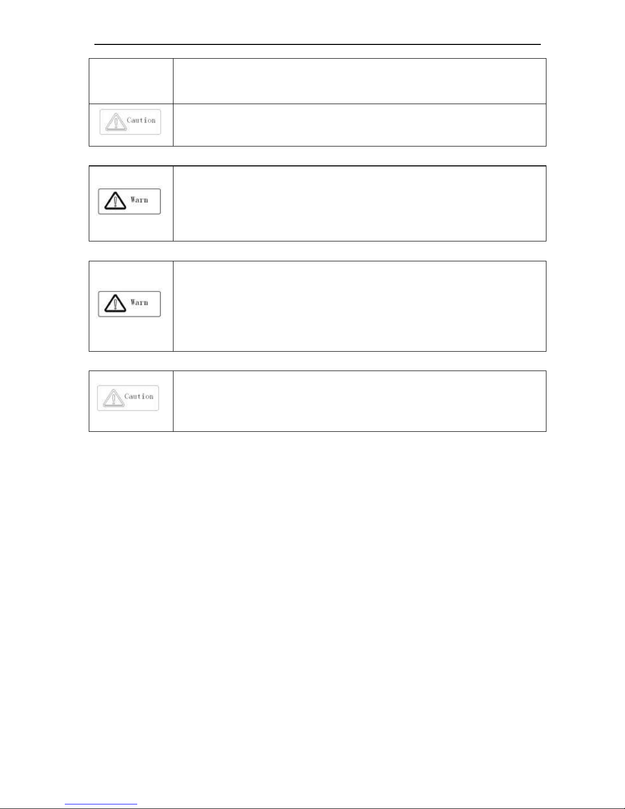
● Installation and wiring regulation
● Only professional trained person can operate it.
● Power wire, motor wire and control wire should be all connected firmly. Earth must be reliable
and earth resistance must be lower than 10Ω.
● Before opening the inverter, please disconnect all related equipment power supply and make
sure the mains DC voltage is in safe range and operate after 5mins.
● Human body electrostatic will damage inner sensitive components seriously. Before
operation, please follow ESD measures. Otherwise, there is danger of iverter damage.
● Inverter output voltage is pulse wave. If components such as capacitor which improves power
factor and pressure-sensitive resistance for anti-thunder and so on are installed at the output
AC90 TENSION CONTROL FREQUENCY INVERTER MANUAL BASIC OPERATION AND TRIAL RUN
3
side, please dismantle them or change to input side.
● No switch components such as breaker and contactor at the output side. (If there must be
one, please make sure the output current is 0 while the switch acting).
● The power supply cable and motor cable specifications must satisfy all conditions in table 3-7
3-8 .
● Run regulation
● Inverter runs at high voltage. So dangerous voltage is in some components inevitably.
● No matter where the fault is, there is danger of serious accident, even human body injury
what means dangerous malfunction possibility. So there must be additional external prevent
measures or other safety devices, such as independent current limiting switch, machinery
fense and so on.
● Maintenance regulation
● Only Shenzhen Veichi Electric co., ltd service department or its authorized service center or
professional person trained and authorized by Veichi can maintain the products. They should
be very familiar with the safety warning and operation gist in this manual.
● Any defective components must be changed in time.
● Before opening the inverter to repair please cut power supply of all related equipments and
ensure mains DC voltage in safe range. And please do operation after 5 mins.
● Dismantlement and disposal regulation
● Packing case can be reused. Please keep them and reuse or send back to maker.
● Dismantled metal components are retractable and can be reused.
● Some components such as electrolytic capacitor are harmful to environment. Please dispose
accronding to environmental protection departments.
AC90 TENSION CONTROL FREQUENCY INVERTER MANUAL BASIC OPERATION AND TRIAL RUN
4
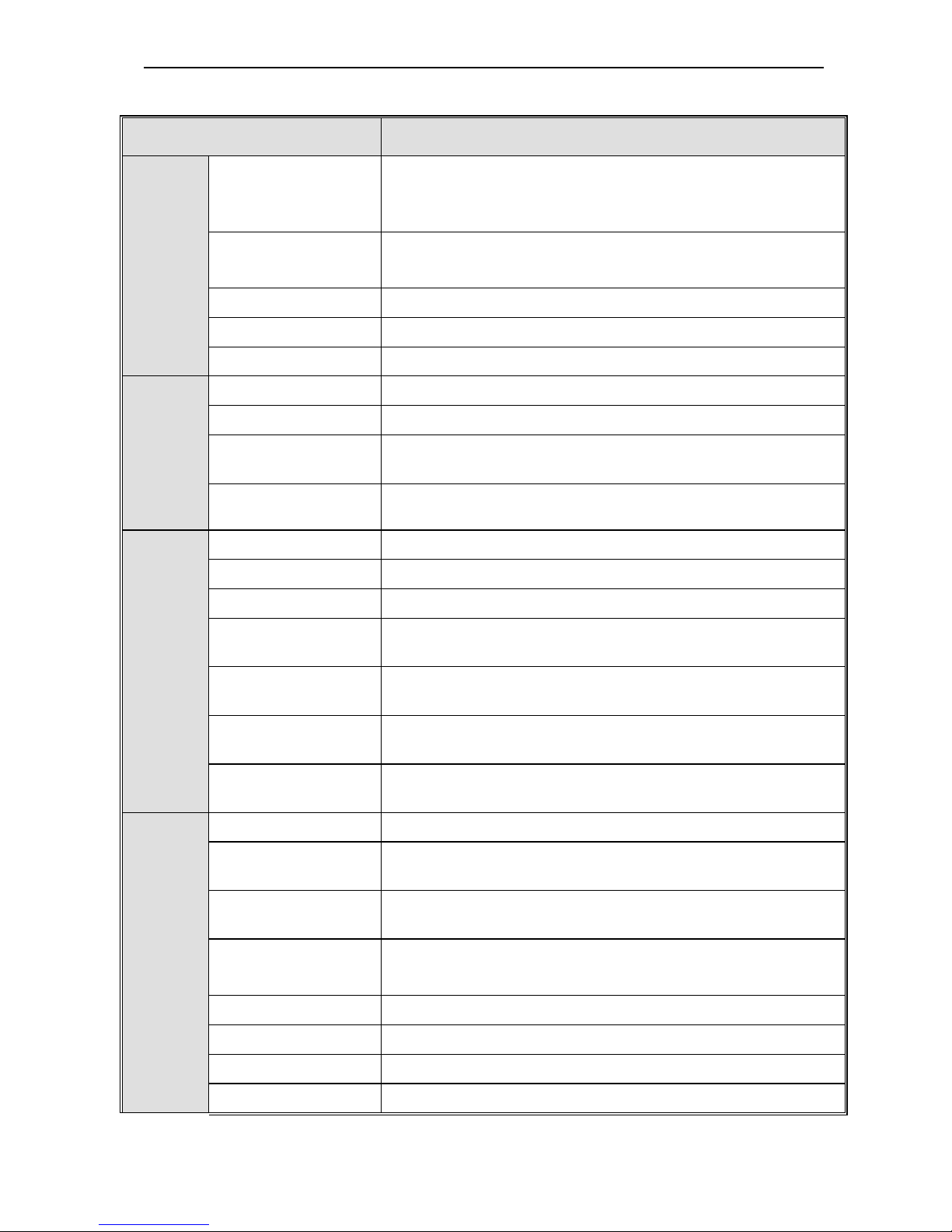
1.2 Technic criterion
Items Criterion
Power
input
Voltage,frequency
Single phase220V 50/60Hz
Three phase380V 50/60Hz Three phase220V 50/60Hz
Three phase660V 50/60Hz Three phase1140V 50/60Hz
Allowable fluctuations
Voltage:320V~440V; voltage unbalance rate:<3%;
Frequency:±5% aberration rate: as IEC61800-2 required
Inrush current Lower than rated current
Power factor ≥0.94(with DC reactor)
Efficiency ≥96%
Output
Output voltage Output under rated condition:3 phase, 0~input voltage, inaccurancy<5%
Output frequency range G type:0-320Hz
Output frequency
accuracy
Max frequency ±0.5%
Overload capacity
G type:150% rated current/1 min,180% rated current/10s,200% rated
current/0.5s
Main
Control
performance
Motor control mode VC without PG, VC with PG, V/F without PG, V/F with PG
Modulate mode Optimized SVPWM mode
Carrier frequency 0.6~15.0kHz,randomized carrier-wave
Speed range
VC without PG: rated load 1:100
VC with PG: rated load 1:1000
Steady speed accuracy
VC without PG: ≤1% rated synchronized speed
VC with PG: ≤0.02% rated synchronized speed
Starting torque
Flux VC without PG: when 0.5Hz, 180% rated torque
Flux VC with PG: when 0Hz, 200% rated torque
Torque response
Flux VC without PG: ≤20ms
Flux VC with PG: ≤10ms
Product
basic
functions
Tension control Tension setting calculation;Tension tape calculation
Roll diameter calculation
Linear speed calculation method;Thickness calculation method; Time integral
calculation method
Torque control
Torque setting calculation; Torque ACC/DEC time; Torque compensation;
Speed limit
Speed control
Frequency setting; ACC/DEC time setting; Run direction setting; Speed
setting; Torque setting
Motor parameter study Rotate auto studay; Static auto studay
Auto voltage adjust Auto keep stable output voltage while the net voltage waves
Auto energy saving run Auto output best voltage according to actual load need to save energy
Auto limit current Auto limit current in running to prevent
AC90 TENSION CONTROL FREQUENCY INVERTER MANUAL BASIC OPERATION AND TRIAL RUN
5
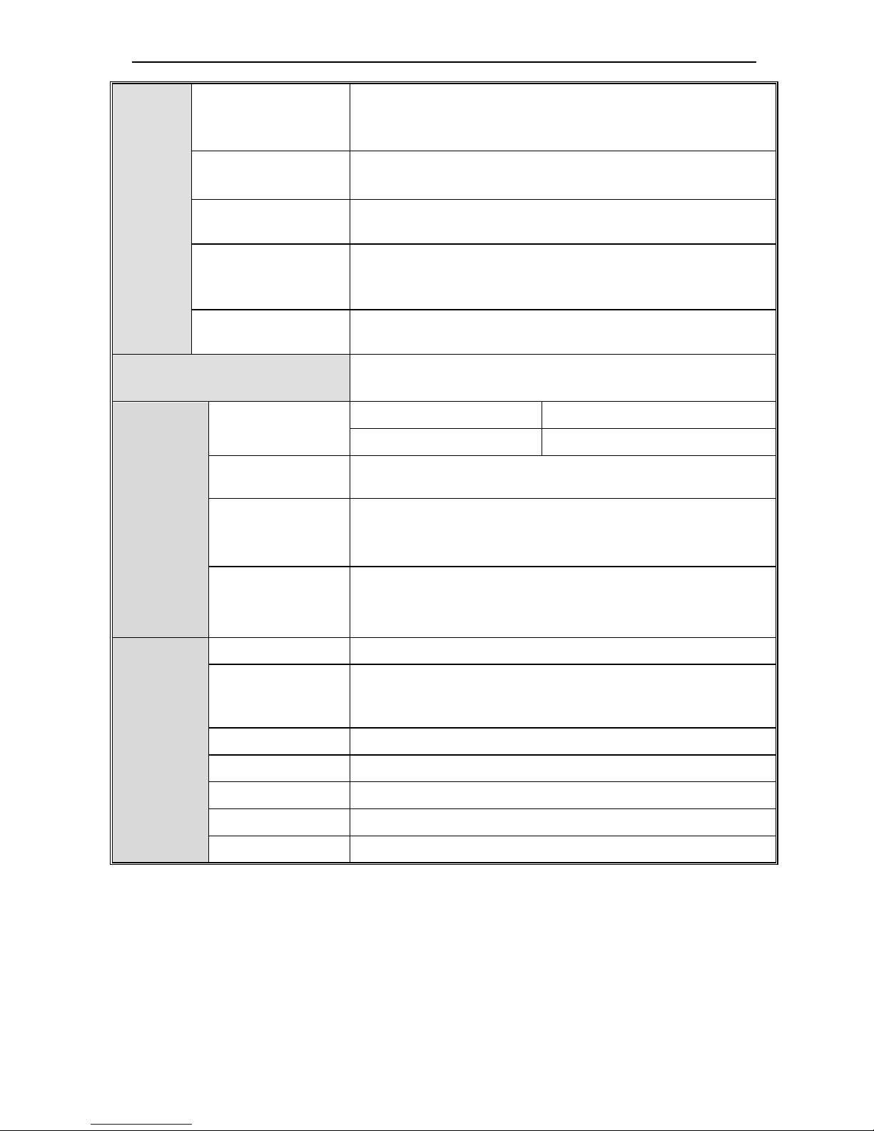
Frequency set channels
Keyboard digital set, keyboard potentionmeter, analog voltage terminal
VS1/VS2, analog current terminal AS, communication given and multi channels
terminal selection, master-slave channels combination.
Feedback input channel
Voltage terminal VS1/VS2, current terminal AS, communication given, pulse
input PUL.
Running command
channel
Operation panel given, external terminal given, communication given.
Input command signal
Start, stop, FOR/REV, JOG, multi-step speed, free stop, reset,
Acceleration/Deceleration time selection, frequency set channel selection,
exterior fault alarm.
Exterior output signal
One relay output, two collector output, 0~10V output,4~20mA
output,frequency pulse output.
Protection function
Overvoltage, undervoltage, current limit, overcurrent, overload, electric
thermalrelay, overheat, overvoltage stall, data protection.
Keyboard
display
LED display
Single file 4 digital tube display Can monitor one state variable
Two file 4 digital tube display Can monitor two state variables
Parameter copy
Can upload or download function code information of inverter to realize fast
parameter copy.
State monitor
Output frequency, given frequency, output current, input voltage, output
voltage, motor speed, PID feedback, PID given value, module temperature,
input/output terminal condition.
Fault alarm
Ouve-voltage, under-voltage, over-current, short circuit, open phase, overload,
overheat, over-voltage speed lost, current limit, or data protection is destroyed;
Fault running state; Fault history.
Environ
ment
Install place Indoor, altitude ≤1000m,no corrosive air or direct sunshine
Temperature,
humidity
-10 ~ +40℃(hanging type)
-10 ~ +45℃(cabinet type)
20%—90%RH(no condensation)
Vibration Under 20Hz≤0.5g
Store temperatue -25—+65℃
Installation Hanging type, cabinet type
Protection IP20
Cooling mode Forced cooling
Table 1-1: Technic criterion
AC90 TENSION CONTROL FREQUENCY INVERTER MANUAL BASIC OPERATION AND TRIAL RUN
6
Chapter 2 Before Use
2.1 Purchase inspection
Pls check whether any package is damaged while receiving the product you ordered. If the package is ok, pls open it
and check the inverter. If damage caused in transport, it is not duty of Veichi company.But please contact Veichi or the
transport company immediately.
After checking the product, please also check if the model is the one you ordered.The model of the product is on the
nameplate “MODEL”column. If the model is not in accordance with your need, please contact the agent or the sales
departments in our company.
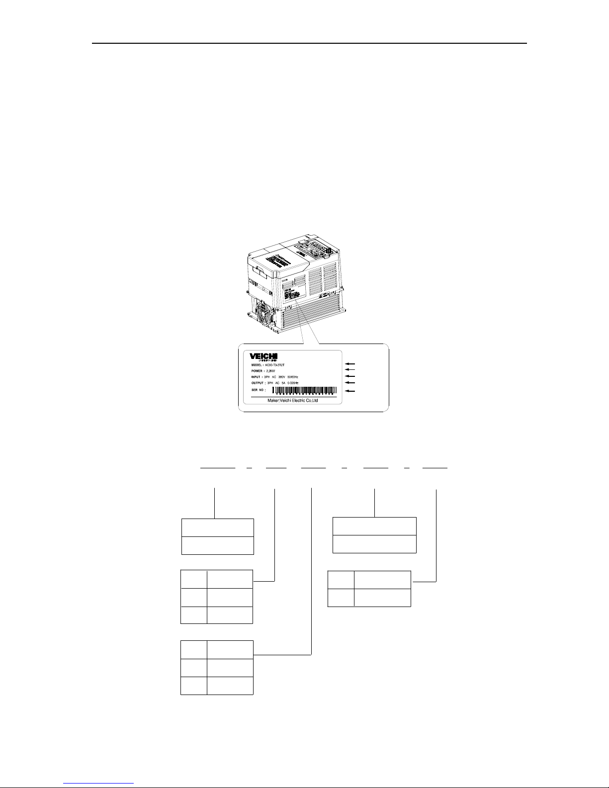
2.2 Nameplate
Nameplate position and content
INPUT
MODEL
POWER SUPPLY
PRODUCTION
OUTPUT
SERIES NO
Drawing2-1:AC90 series inverter nameplate position
Model explainatio
voltagesymbol
Inverter type
symbol
(pls refer drawing 2-1,2-2)
Universal
symbol
380V
3
2
220V
3
(5)
AC90
(1)
T
(2)
2R2
(3)
3-phase
voltage
motor adptor power(kw)
(4)
T
Inverter series
T
S
single-phase
AC90 series
T
Drawing 2-2:AC90 series inverter nameplate meaning and naming rules

AC90 TENSION CONTROL FREQUENCY INVERTER MANUAL BASIC OPERATION AND TRIAL RUN
7
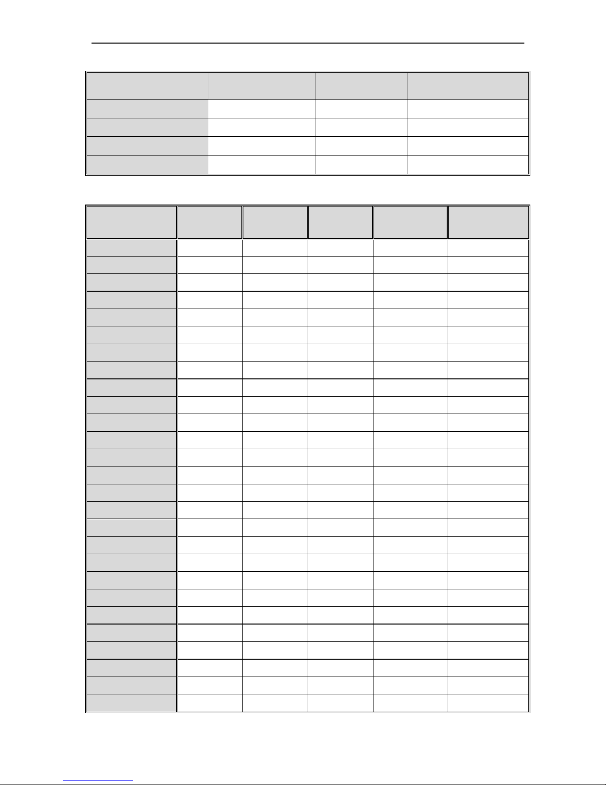
2.3 Standard models and rated parameters
Single phase 220V
Table 2-1:AC90 single phase 220V series inverter models and rated parameters
Three phase 380V
Table 2-2:AC90 three phase 380V series inverter models and rated parameters
Model
Max adaptive
motor
Rated current
Model
Max
adaptive
motor
Rated
current
AC90-S2-R40T 0.4kW 2.5A AC90-S2-1R5T 1.5kW 7A
AC90-S2-R75T 0.75kW 4A AC90-S2-2R2T 2.2kW 10A
Model
Max adaptive
motor
Rated current
Model
Max
adaptive
motor
Rated
current
AC90-T3-R75T 0.75kW 2.5A AC90-T3-110T 110kW 210A
AC90-T3-1R5T 1.5kW 3.7A AC90-T3-132T 132kW 250A
AC90-T3-2R2T 2.2kW 5A AC90-T3-160T 160kW 310A
AC90-T3-004T 4kW 10A AC90-T3-185T 185kW 340A
AC90-T3-5R5T 5.5kW 13A AC90-T3-200T 200kW 380A
AC90-T3-7R5T 7.5kW 17A AC90-T3-220T 220kW 415A
AC90-T3-011T 11kW 25A AC90-T3-250T 250kW 470A
AC90-T3-015T 15kW 32A AC90-T3-280T 280kW 510A
AC90-T3-018T 18.5kW 38A AC90-T3-315T 315kW 600A
AC90-T3-022T 22kW 45A AC90-T3-355T 355kW 670A
AC90-T3-030T 30kW 60A AC90-T3-400T 400kW 750A
AC90-T3-037T 37kW 75A AC90-T3-450T 450kW 800A
AC90-BT3-045T 45kW 90A AC90-T3-500T 500kW 860A
AC90-T3-055T 55kW 110A AC90-T3-560T 560kW 990A
AC90-T3-075T 75kW 150A AC90-T3-630T 630kW 1100A
AC90-T3-090T 90kW 180A AC90-T3-700T 700kW 1260A
AC90 TENSION CONTROL FREQUENCY INVERTER MANUAL BASIC OPERATION AND TRIAL RUN
8
Chapter 3 Installation and Wiring
3.1 Safety Precautions
This chapter explains the warnings for safe use and stable running of the product.
Cautions in use
●While stall the inverter in the closed cabinet, please build in cooling fan, air-condition or other
cooling equipments to ensure the temperature at the air-in port below 40℃. So that the
inverter can work safely and reliably.
●While installing, please use cloth or paper cover the inverter to prevent metal dust, oil, water
and others.And remove it carefully after working.
●While operation, please follow the ESD regulations. Otherwise, the inverter may be damaged.
●While multi inverters are installed in the same cabinet, enlugh space must be left for cooling
fan.
●Inverter can not work over rated range.Otherwise, the inverter may be damaged.
●While transporting the inverter, please hold the firm case. If only hold the pre-cover, there is
danger of inverter main body falling, injury or inverter damage.
Cautions in use motor
●Different motor has different max allowable running speed. Motor can not run over the max
allowable running speed.
●While inverter is running at low speed, the motor auto-cool effect is seriously worse. If motor
runs at low speed for long time, it will be damaged for overheat. If needed, please use special
motor for inverter.
●While constant speed machinery runs at unconstant speed, there maybe sympathetic
vibration. Please install vibration-proof rubber under motor rack or use jumping frequency
control function.
●While using frequency inverter or working frequency power supply to drive, the torque
characteristic are different. Please do confirm the torque characteristic of the equipment
connected.
●The rated current of shift gear motor is different from that of standard motor. Please confirm it
and choose the right frequency inverter. Moreover, please do switch the pole while the inverter
input current is 0. Otherwise it may bring inverter protection or damage.
●The rated current of diving motor is higher than that of standard motor, please confirm it and
choose the right inverter.
●While the wire between motor and inverter is long, the max torque of the motor will reduce for
voltage drop. So please use thick cable while the distance between the motor and the inverter
is long.
AC90 TENSION CONTROL FREQUENCY INVERTER MANUAL BASIC OPERATION AND TRIAL RUN
9
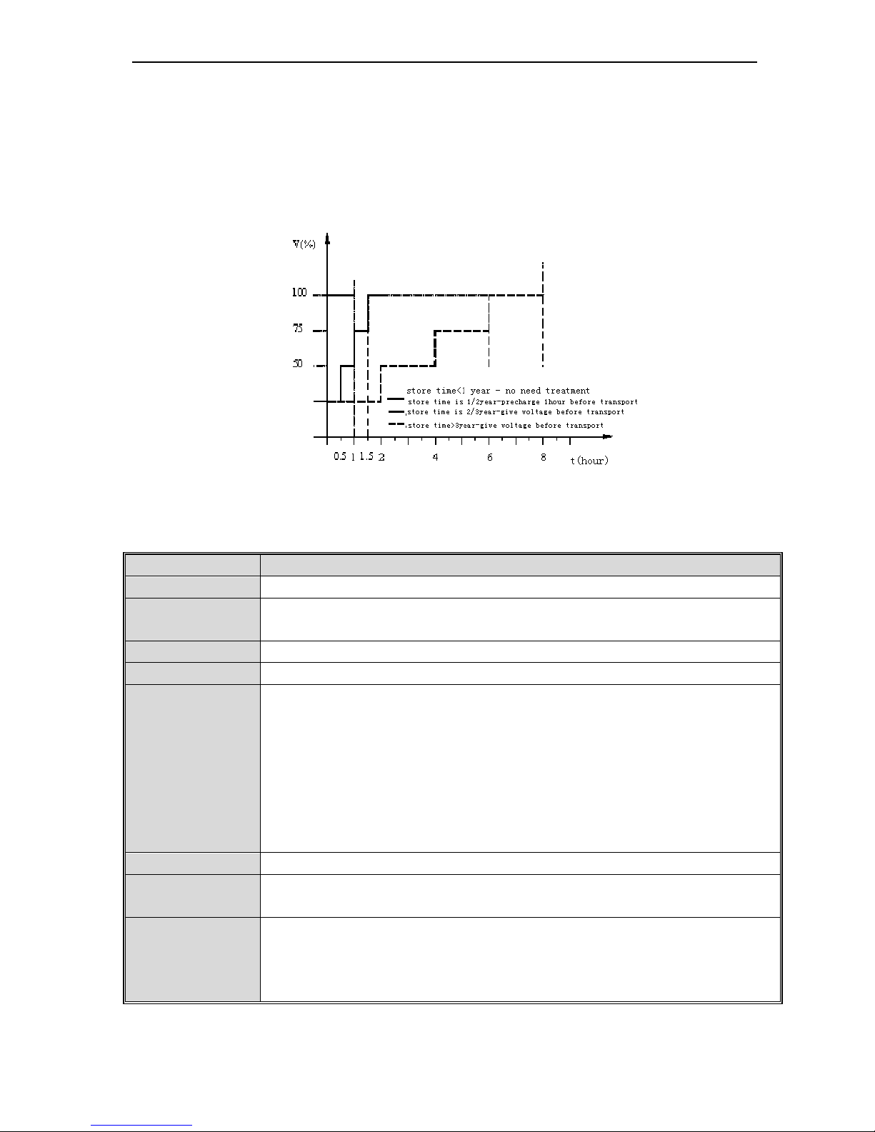
3.2 Treatment for inverter after longtime store
If the inverter store time is over one year, you must precharge the aluminium capacitor in the inverter again and install
the inverter after the aluminium capacitor characteristic recovering. For the specific method, please follow the grads in
belowing chart and give corresponding proportional voltage for every grad more than 30 mins while the inverter is
no-load.
If the input voltage of one grad is at the action critical point of contactor, fan or other equipments, please increase or
reduce the corresponding input voltage for the grad to avoid any component working under critical state.
Chart 3-1: treatment for inverter after longtime store
3.3 Inverter stable running environment
Installation environment is very important to the best use of this product for long time. Pls install this product in the
enviorment as the following chart requirement.
Environment Requirement
Install place Indoor without direct sunshine
Install temperature
-10 ~ +40℃(hanging type)
-10 ~ +45℃(cabinet type)
Store temperature -20 ~ +60℃
Humidity <95%RH, no condensation
Surrounding
Please install the inverter in place as follows:
● Place without oil mist, corrosive gases, flammable gase, dust or etc.
● Place without metal dust, oil, water or etc into inverter (please do not install inverter on
flammable material such as food and etc).
● Place without radioactive material or flammable material.
● Place without poisonous gases or liquid.
● Place with very little salification erosion.
● Place whihout direct sunshine.
Altitude <1000m
Vibration
<10~20Hz:9.8m/s2
<20~55Hz:5.9m/s2
Installation and
cooling
● Inverter can not be installed horizontally must be installed vertically.
● Please independently install high heating equipments such as braking resistor and etc which
can not be installed in the same cabinet with inverter, installed at the air-in port of the inverter
is strictly prohibited.
Chart 3-1:AC90 series inverter running environment condition
AC90 TENSION CONTROL FREQUENCY INVERTER MANUAL BASIC OPERATION AND TRIAL RUN
10
● In order to improve the product stability, pls do not use the inverter where temperature changes sharply. While using
in closed space such as control cabinet, please use cooling fan or air-condition to cool inverter to avoid temperature
over limit range. Please also prevent inverter from freeze, too low temperature may cause components freeze fault.
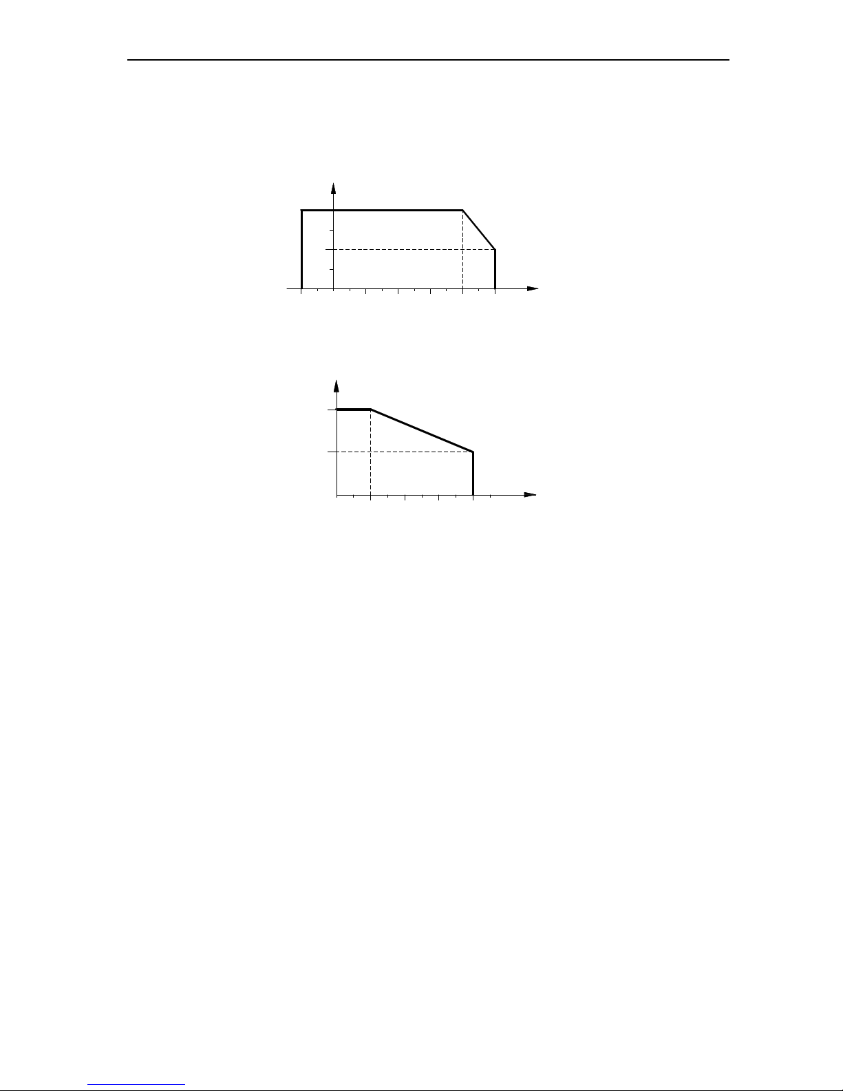
● Derate according to the chart while over temperature limit.
30
25
100
75
50
4020100-10 50
TEMPERATURE(℃)
PERMIT OUTPUT CURRENT(%)
Chart 3-2:AC90 series inverter derating surve while over permit temperature temperature
● Derate according to the chart while over altitude limit.
0
1000 2000 4000
80
100
3000 ALTITUDE(M)
PERMIT OUTPUT CURRENT(%)
Chart 3-3:AC90 series inverter derating surve while over permit altitude
3.4 EMI Protection
The inverter is designed to be used in industrial environment with strong electromagnetic interference. Generally
speaking, if the installation quality is good, it is ensured that the inverter can work safely without fault. Please install the
inverter according to the following rules to ensure stable running and avoid electromagnetic interference impact.
● Ensure that all equipments in the cabinet have been connected reliably to the common Y-type earth point or earth
bus with thick and short cable. The motor earth should be as close as possible. Please do not connect the motor
case to the inverter earth terminal or the protective area of control system.
● Ensure that all equipments connected to the inverter have been reliably connected to the same earth net or Y-type
earth point with thick and short cable.
●The conductor has better to be flat and with multi core, what has lower resistance at high frequency.
●The cutting terminal should be as soigne as possible. Unshielded wire section must be as short as possible.
●In control cable wiring, it should be as far from the power supply cable and motor cable as possible. And independent
cable trough should be used. While the control cable must cross to the power supply cable or motor cable, it should
be 90º vertical cross.
● Ensure that the contactor in the cabinet has wave surge suppresser. Or‘R-C’damping circuit is connected to the
winding of AC contactor. Voltage dependent resistor corresponding to the winding voltage is used. And freewheel
diode or components such as voltage dependent resistor corresponding to the winding voltage are connected to DC
contactor. It is very important while contactor, controlled by output relay of inverter, acts frequently.
● Cable connected to motor should be shielded cable or armoured cable. The two barriers are earthed reliably by
cable grounding card.
● Build noise filters at the input side to reduce electromagnetic interference from other equipments at the power grid
side. The noise filter should be as close to the inverter power input terminal as possible. Meantime, the filter must
earth reliably as the inverter.
AC90 TENSION CONTROL FREQUENCY INVERTER MANUAL BASIC OPERATION AND TRIAL RUN
11
● Build noise filters at the output side to reduce radio interference and inductive disturbance. The noise filter must be
as close to the inverter output terminal as possible. Meantime, the filter must earth reliably as the inverter.
●Anytime, control circuit wire should be shielded cable.
●Add zero phase reactor in power supply wire near inverter input terminal and add zero phase reactor in the motor
wire near inverter output terminal to reduce electromagnetic interference to the inverter efficiently.
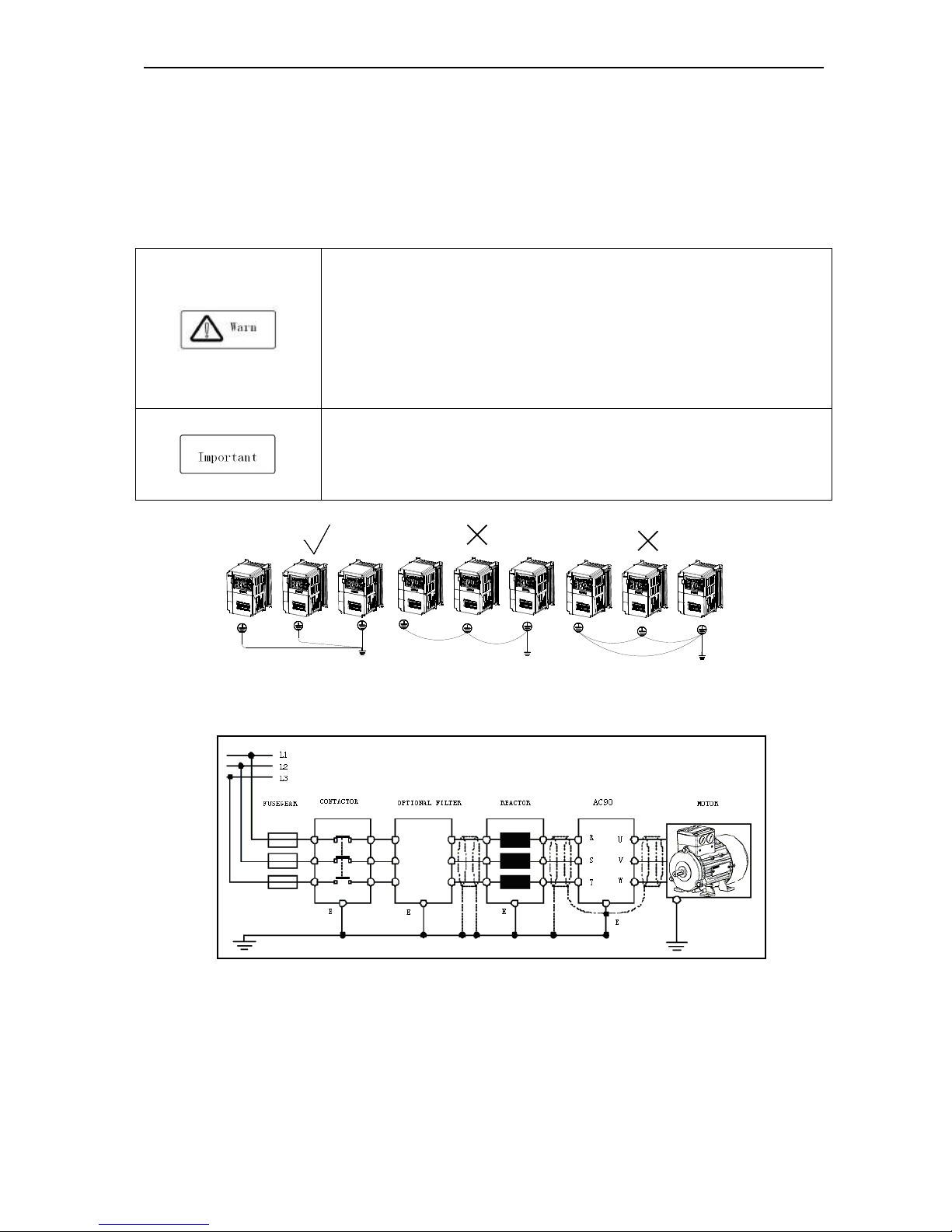
● Earthing Right and reliable earthing is the basic condition of safe and reliable running of the product. For right
earthing, please read the following notice carefully.
●In order to avoid electric shock, earthing cable should be the size as electric
equipment technic standard required and cable length should be as short as
possible. Otherwise, inverter leakage current will cause unstable potential of the
earthing terminal which is far from the earthing point, and electric shock accident will
happen frequently.
●Earth terminal must be earthing. Earth resistance must be below 10Ω. Otherwise,
there is danger of death.
● Please do not share earth cable with welder or other big current/pulse power
equipment. Otherwise, inverter will act abnormally.
●While multi inverters are used at the same time, please do not wind the earth wire to
loop-type. Otherwise, inverter will act abnormally.
Chart 3-4: multi AC90 series inverters united earthing
Chart 3-5:AC90 series inverter system earthing
Remark: motor must earth as close as possible. Motor case can not be connected to the inner earth terminal of the
inverter. It also can not share the earth net with the control system.
AC90 TENSION CONTROL FREQUENCY INVERTER MANUAL BASIC OPERATION AND TRIAL RUN
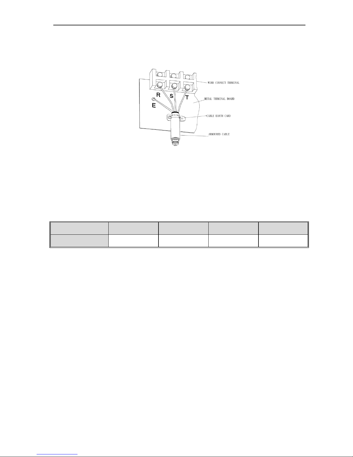
12
Shield of inverter power cable, motor cable, control cable Cable
Shielding layer (reticulate/armoured) should be winded reliably by cable earth card and fix to inverter earth piece by bolt.
Please refer to the following chart.
Chart 3-6:Cable earth card for cables earthing
●Corresponding relationship between inverter/motor cable length and carrier frequency.
While cable distance between inverter and motor is long (especially low frequency output), cable voltage drop will make
motor torque reduce. Further more, cable HF leakage current will increase. Then inverter output current will increase,
that will cause inverter over-current trip. The current detection accuracy and running stability will be impacted. Please
follow as below chart to adjust carrier frequency according to the cable length. While the cable distance is over 100m,
please adopt distributed capacity reduce measure (Such as “no metal conductor covers cable”, “wire each phase cable
apart” and so on).
Cable length <20m 20~50m 50~100m >100m
Carrier frequency 0.6~16kHz 0.6~8kHz 0.6~4kHz 0.6~2kHz
Chart 3-2:Corresponding relationship between inverter/motor cable length and carrier frequency
AC90 TENSION CONTROL FREQUENCY INVERTER MANUAL BASIC OPERATION AND TRIAL RUN
13
3.5 Machinery installation
Installation notice and related requirement
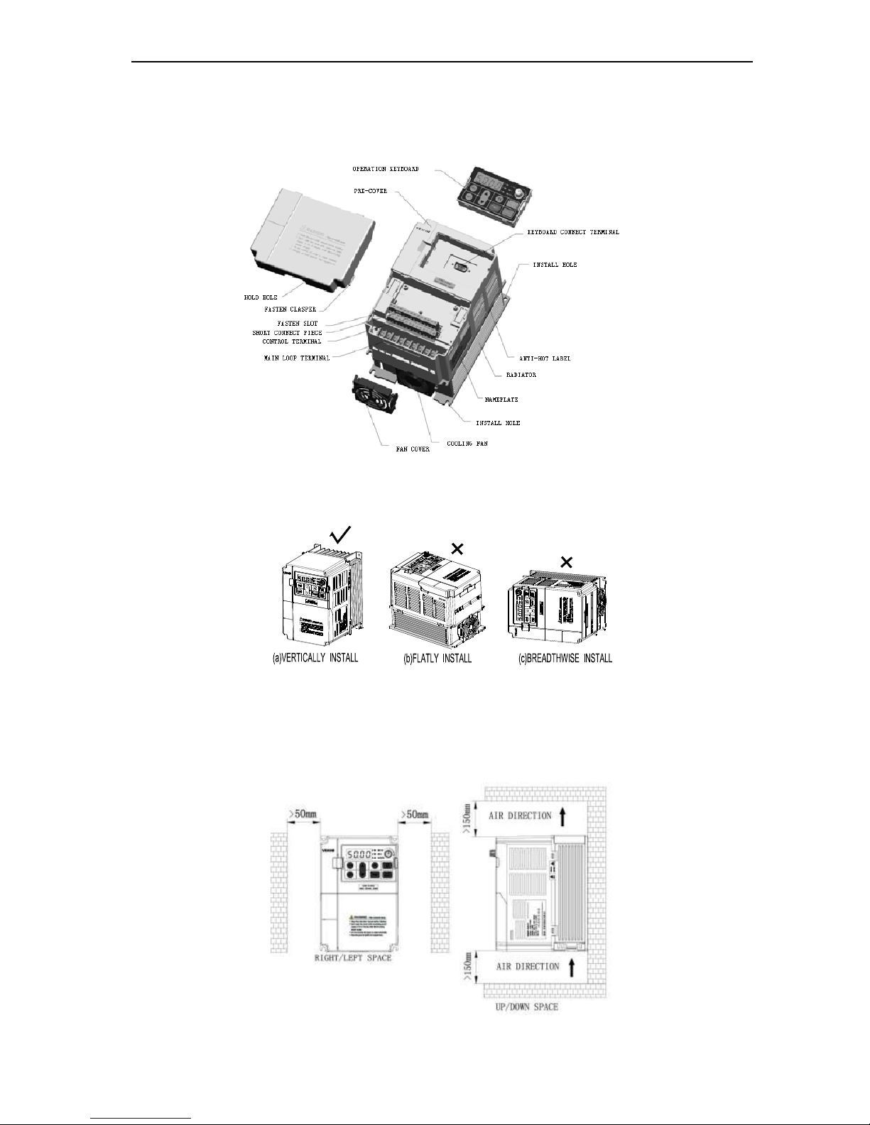
● AC90 inverter components
Chart 3-7:AC90 series inverter components
● Installation direction
To prevent inverter cooling effect reducing, please do install the inverter vertically.
Chart 3-8:AC90 series inverter installation direction
● Installation space
Single machine installation: to ensure enough ventilation and wiring space for inverter cooling, please follow installation
conditions as follows. The back of the inverter should stick to the wall. So that the surrounding air of radiator can flow
freely to ensure the cooling effect.
Chart 3-9:Single AC90 series inverter installation space
AC90 TENSION CONTROL FREQUENCY INVERTER MANUAL BASIC OPERATION AND TRIAL RUN
14
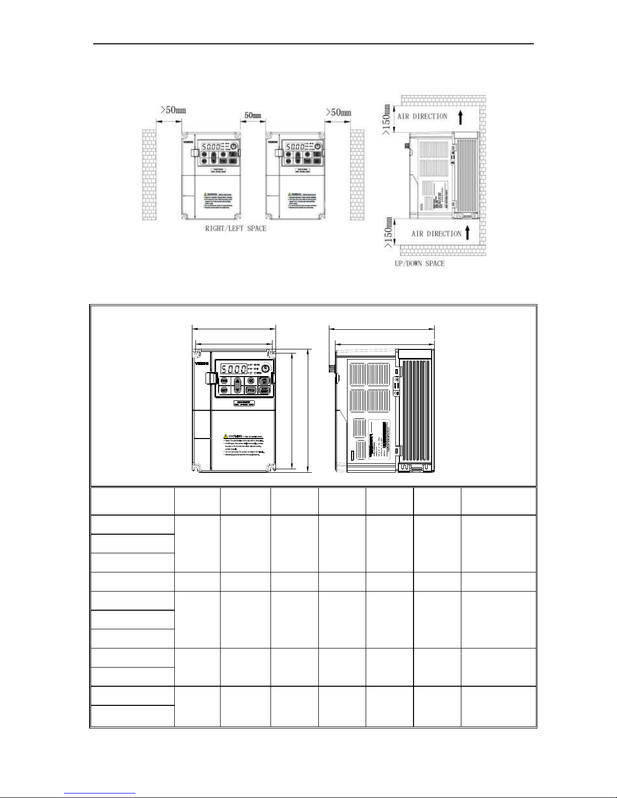
Multi inverters paratactic installation: while installing multi inverters in cabinet, please ensure installation space as
follows.
Chart 3-10: Multi AC90 series inverters paratactic installation space requirement
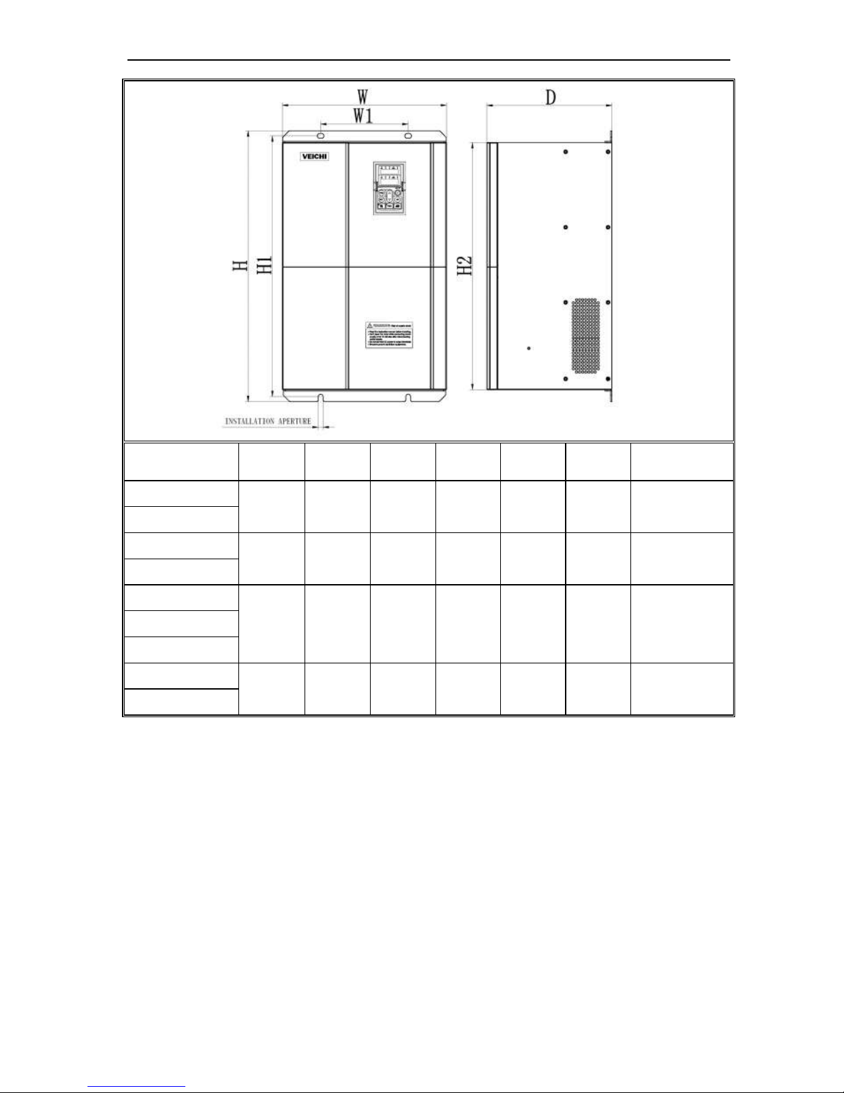
Dimension of inverter and keyboard
W1
W
H1
H
D1
D
MODEL W W1 H H1 D D1
INSTALLATION
APERTURE
AC90-S2-R40T
122 112 182 171 154.5 145 ф5
AC90-S2-R75T
AC90-S2-1R5T
AC90-S2-2R2T 159 147.2 246 236 157.5 148 ф5.5
AC90-T3-R75T
122 112 182 171 154.5 145 ф5
AC90-T3-1R5T
AC90-T3-2R2T
AC90-T3-004T
159 147.2 246 236 157.5 148 ф5.5
AC90-T3-5R5T
AC90-T3-7R5T
195 179 291 275 167.5 158 ф7
AC90-T3-011T
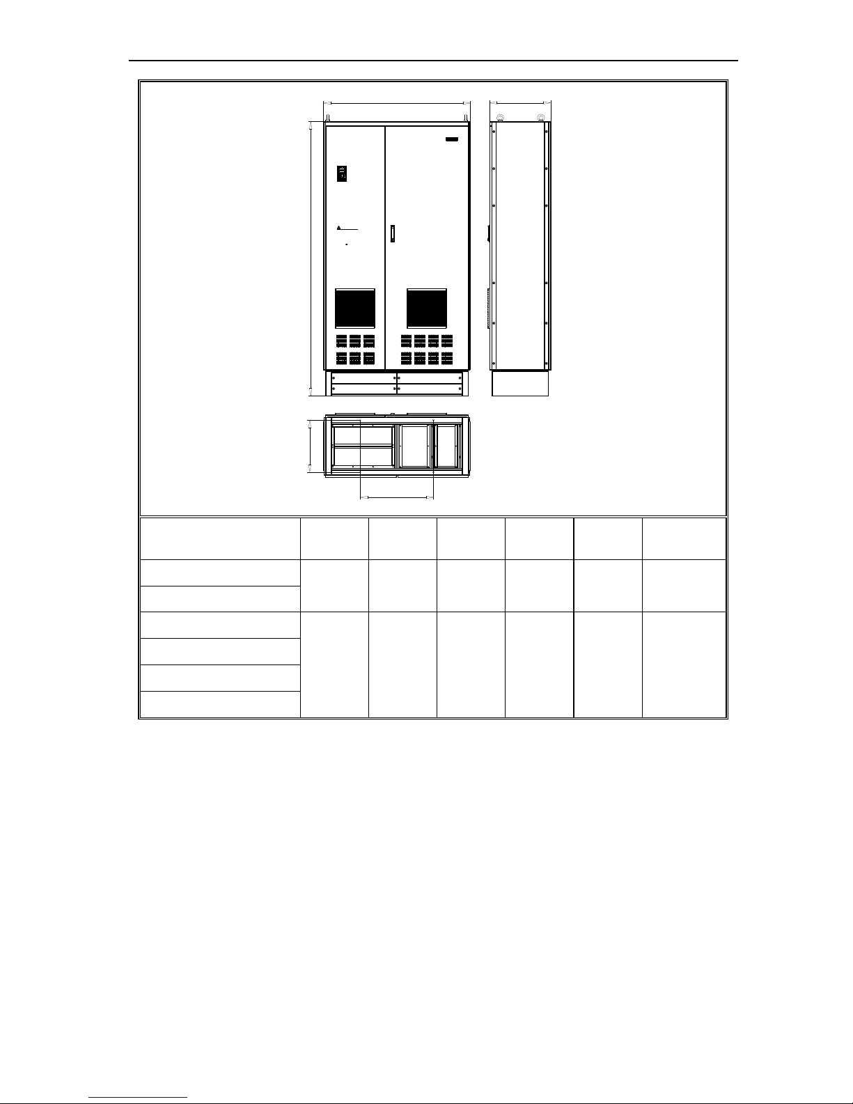
AC90 TENSION CONTROL FREQUENCY INVERTER MANUAL BASIC OPERATION AND TRIAL RUN
15
MODEL W W1 H H1 H2 D
INSTALLATION
APERTURE
AC90-T3-015T
255 160 434 418 390 224 ф7
AC90-T3-018T
AC90-T3-022T
285 200 493 473 445 265 ф9
AC90-T3-030T
AC90-T3-037T
375 200 620 597 567 286 ф11
AC90-T3-045T
AC90-T3-055T
AC90-T3-075T
466 300 760 735 700 320 ф11
AC90-T3-090T
AC90 TENSION CONTROL FREQUENCY INVERTER MANUAL BASIC OPERATION AND TRIAL RUN
16
Risk of electric shock
Please follow the safety instructions
in the manual before installation or
operation.
Wait 10 minutes f or capacitor
discharge after disconnecting
power supply.
Do not conn ect A C power to output
terminals UVW.
To conform to requiremen ts,
make sure to gro und the supply
neutral for 380V c lass .
After open ing the manual switch
between the drive and motor,
please wait 10 m inutes bef ore
inspecting, performing maintenan ce
or wiring the drive .
WARNING
W
H1
H
D
W1
D1
Risk of electric shock
Please follow the safety instruc tions
in the manual befo re insta llation o r
operation.
Wait 10 min utes f or capac itor
discharge after disconnec ting
power supply.
Do not conn ect A C power to output
terminals UVW.
To conform to requiremen ts,
make sure to ground the supply
neutral for 380V cl ass .
After open ing the manual switch
between the drive and motor,
please wait 10 minutes before
inspecting, perfo rming maintenance
or wiring the drive .
WARNING
W
H2
H3
D
W2
H4
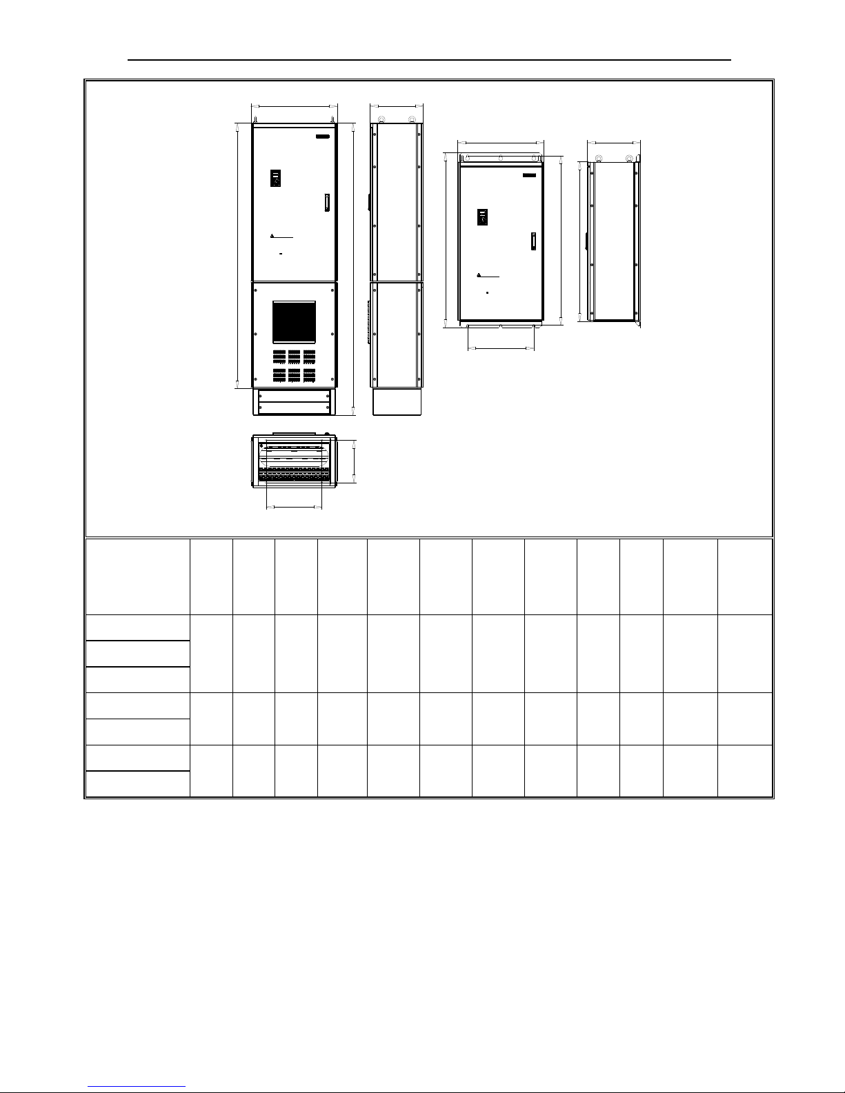
Cabinet inverter
Hang inverter
MODEL W W1 W2
H H1 H2 H3 H4 D D1
installatio
n aperture
of cabinet
inverter
installation
aperture
of hang
inverter
AC90-T3-132T
590 350 430 1800 1600 1160 1050 1123 400 320
ф11 ф14 AC90-T3-160T
AC90-T3-185T
AC90-T3-200T
650 420 500 2200 2000 1318 1200 1276 400 321
ф13 ф16
AC90-T3-220T
AC90-T3-250T
750 400 600 2200 2000 1325 1200 1278 400 320
ф13 ф18
AC90-T3-280T
AC90 TENSION CONTROL FREQUENCY INVERTER MANUAL BASIC OPERATION AND TRIAL RUN
17
W
H
D
W1
D1
Risk of electric shoc k
Please follow the safety instructions
in the manual before installation or
operation.
Wait 10 minutes for capacitor
discharge after disconnecting
power supply.
Do not connect AC power to output
terminals UVW.
To conform to requirements,
make sure to ground the supply
neutral for 380V class.
After opening the manual switch
between the drive and motor,
please wait 10 minutes before
inspecting, performing maintenance
or wiring the drive.
WARNING
MODEL W W1 H D1 D
INSTALLATIO
N APERTURE
AC90-T3-315T
800 400 2200 361 450 ф13
AC90-T3-355T
AC90-T3-400T
1200 600 2200 417 550 ф13
AC90-T3-450T
AC90-T3-500T
AC90-T3-560T
Chart 3-3:AC90 series inverter dimension
AC90 TENSION CONTROL FREQUENCY INVERTER MANUAL BASIC OPERATION AND TRIAL RUN
18
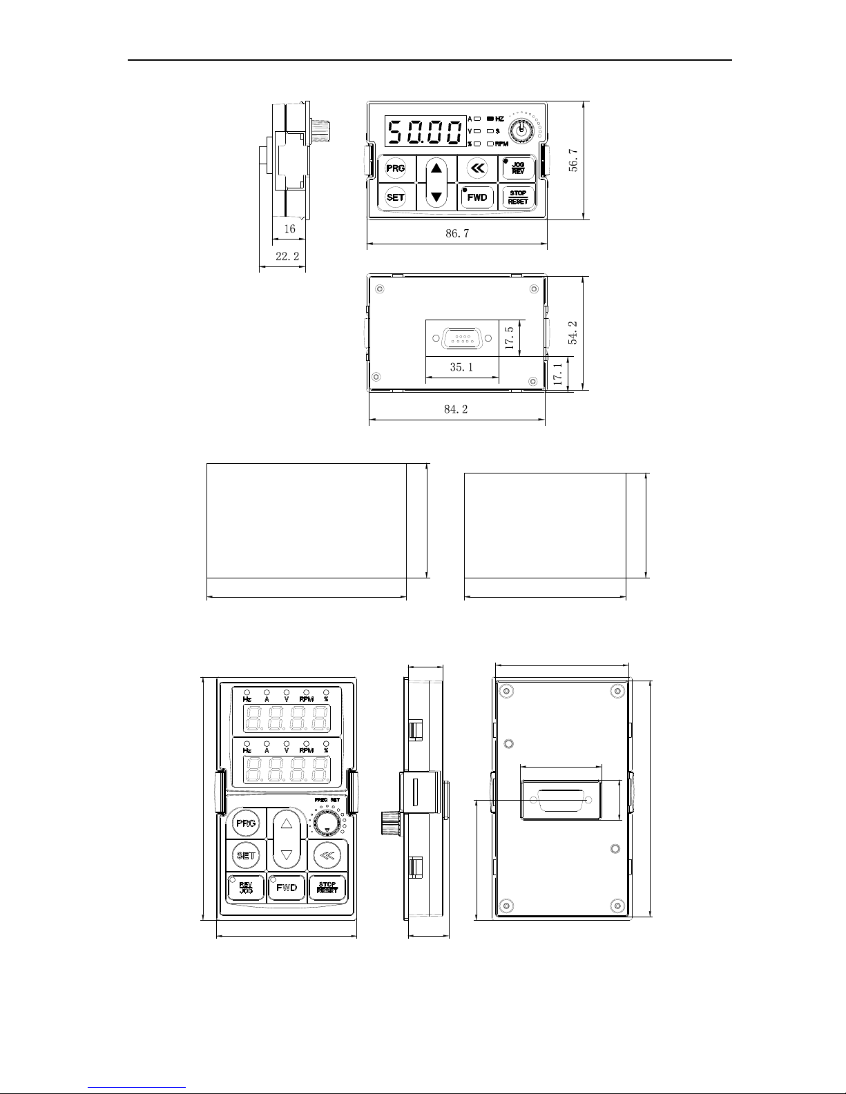
Keyboard dimension
Chart 3-11:AC90 series inverter 1 line LED keyboard dimension
59,5
104,5
54,5
84,5
Mouth keyboard with box
Mouth keyboard without box
Chart 3-12:AC90 series inverter mouth for 1 line LED keyboard dimension
60.6
110.6
16
18.6
63.8
113.8
37
56.2
19
Chart 3-13:AC90 series inverter 2 line LED keyboard dimension
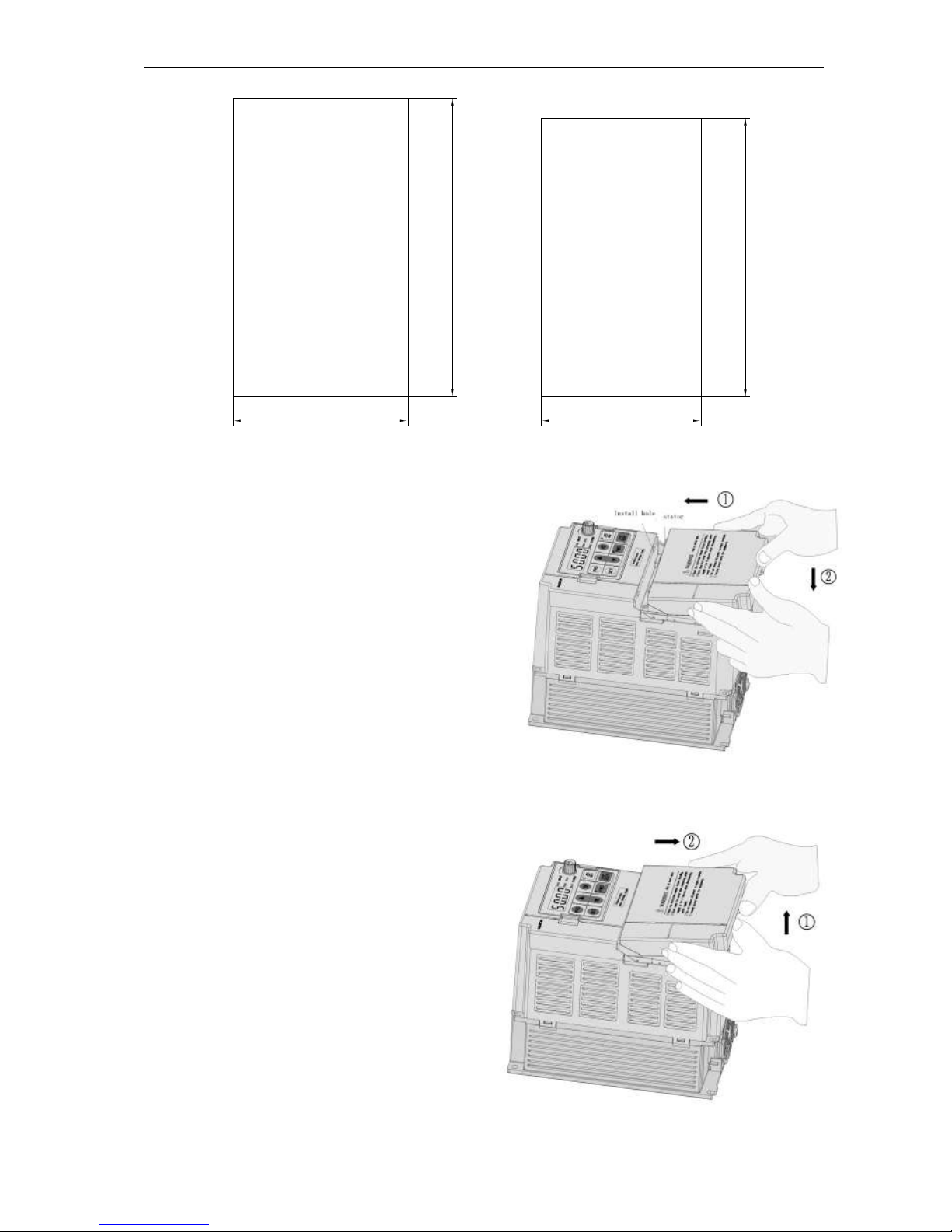
AC90 TENSION CONTROL FREQUENCY INVERTER MANUAL BASIC OPERATION AND TRIAL RUN
19
119
70
Mouth keyboard with box
111
61
Mouth keyboard without box
Chart 3-14:AC90 series inverter mouth for 2 line LED keyboard dimension
Dismantle and install tail-hood
Installation: First the tail-hood upwardly inclines around 15
degrees and inserts the top fixed flat into the fixed hole in
the front cover. Then slightly press the tail-hood downward.
While your hear "Ka", it means that the tail-hood is into the
place.
Chart 3-15:AC90 series inverter tail-hood installation
Dismantlement: At the tail of the frequency inverter, there
is a special dismantlement hole design. Put your finger into
the hole, upwardly pull the cover with a little force until the
buckle between the tail-hood and the crust tear off, and then
remove the tail-hood down.
Chart 3-16:AC90 series inverter tail-hood ismantlement
AC90 TENSION CONTROL FREQUENCY INVERTER MANUAL BASIC OPERATION AND TRIAL RUN
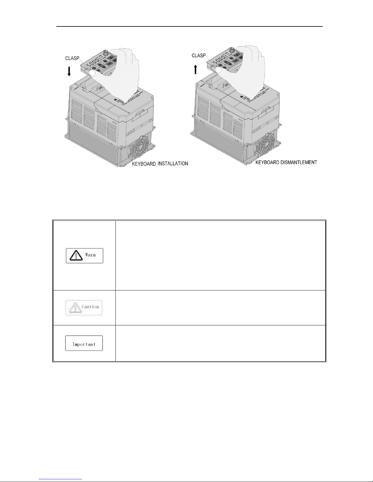
20
Dismantle and install keyboard
Chart 3-17:AC90 series inverter keyboard installation and dismantlement
3.6 Electric installation
This chapter explains the regulations that users have to obey to ensure safe use, best performance and reliable
running.
Safety attention
● Must earth reliably while inverter is running. Otherwise there is danger of casualty and
unstable inverter performance.
● To ensure safe running, only trained professional person can do installation and wiring
job.
● No operation under power connected state. Otherwise there is danger of electric shock
even death.
● Before operation, please cut all related equipments power, ensure that the main circuit
DC current has droped to safe range. And please operate after 5 mins.
● Control cable, power cable and motor cable must be separated. They can not be in the
same cable trough or cable rack.
● This equipment can only be used as the maker states. Please consult Veichi while using
in special case.
● No insulation test for the inverter or the related cable by HV insulation test equipment.
● If the inverter or the peripheral equipment (filer, reactor and etc) needs insulation test,
firstly 500V megohmmeter should be used to test the insulation resistance which should
not be lower than 4MΩ.
AC90 TENSION CONTROL FREQUENCY INVERTER MANUAL BASIC OPERATION AND TRIAL RUN
21
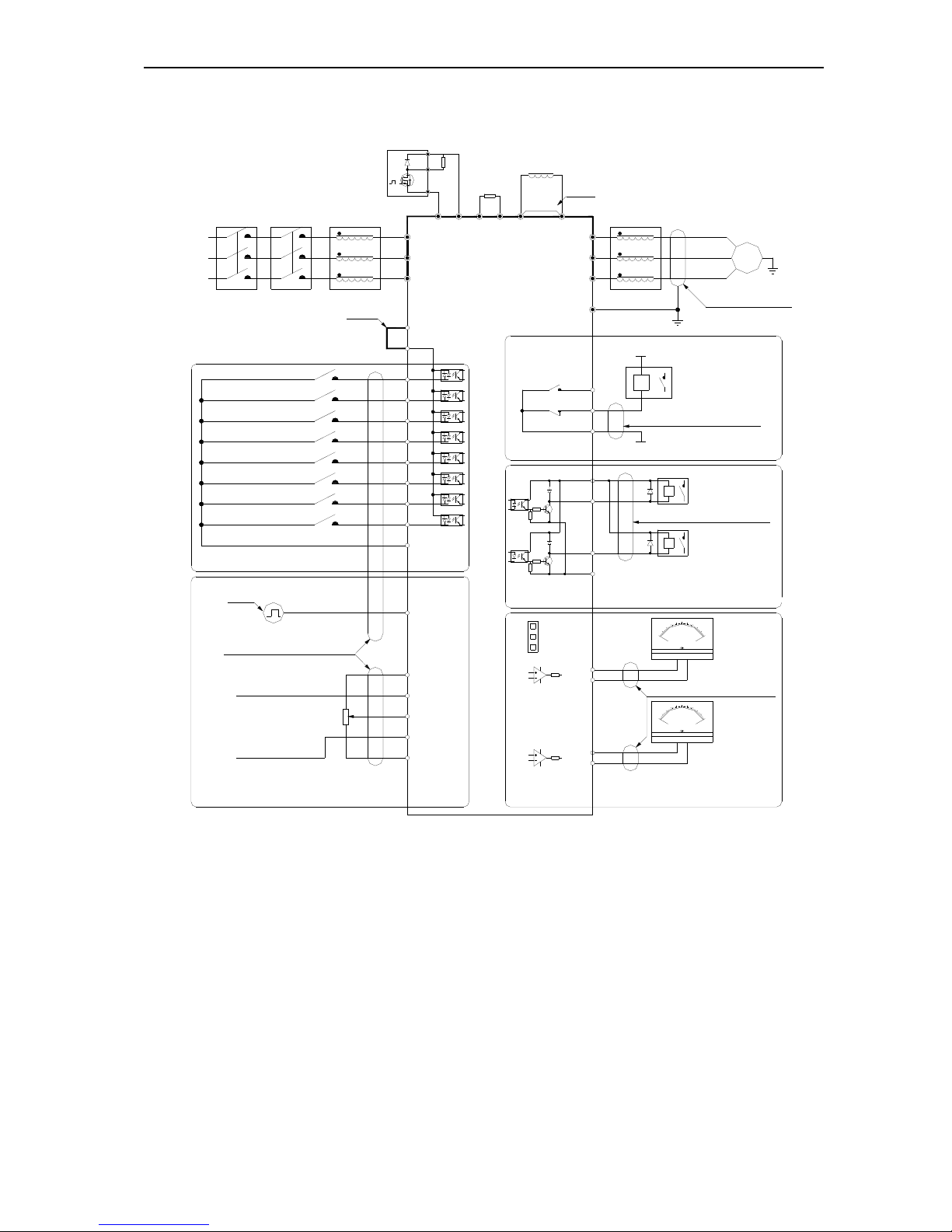
Standard diagram
● Standard diagram
votage analog input
double shielded cable
reverse
forward
double shielded cable
double shielded cable
short connect (note 4)
short connect (note 2)
short connect (note 1)
( )
+
(0~20mA)/(4~20mA)
(
0~5V)/(0~10V)
breaker contactor input reactor
3A/240VAC
5A/30VDC
toggle
switch
J3
J2
J1
double shielded cable
AC0V
AC220V
Passive
connecter
output
COM
Y2
A02
GND
R
T
S
AC90
(-)+( )
PB
+24V
PLC
X2
X1
X5
X6
X4
X3
X8
X7
COM
exterior fa ult output
torque/speed control switch
fault reset
free stop
forward
reverse
multi
function
connect
input
PUL
pulse input
VS1
AS
GND
VS2
AC POWER
INPUT
S
T
R
quency
ntrol input
+10V
current analog input
VR
external braking unit
R
( )
+
P1
external braking
resistance
external DC reactor
output reactor
U
V
W
E
~
M
U
W
V
A01
GND
-
+
_
V
1
0
5
0
+
-
0
10
2
0
mA
_
Y1
+24V
TC
TB
TA
analog
monitor
output
collector
open
output
Chart 3-18:AC90 series inverter standard diagram
Note: 1.While install DC reactor, be sure to dismantle the short connector between terminal P1 and(+).
2.NPN or PNP transistor signal can be selected as input of multi-function input terminal(X1~X8). Inverter
built-in power supply (+24V terminal) or external power supply (PLC terminal) can be choosed as bias
voltage. Factory setting ‘+24V’ short connect with ‘PLC’.
3. Analog monitor output is special output of meters such as frequency meter, current meter, voltage meter
and etc. It can not be used for control operations such as feedback control.
4. As there are multi pulse styles, please refer to the line connect mode description details.
AC90 TENSION CONTROL FREQUENCY INVERTER MANUAL BASIC OPERATION AND TRIAL RUN
22
● Auxiliary terminal output capacity
Terminal Function definition Max output
+10V
10V auxiliary power supply output,constitutes loop
with GND.
50mA
A01/A02 Analog monitor output, constitutes loop with GND.
As frequency,voltage signal, max
output 2mA
+24V
24V auxiliary power supply output,constitutes loop
with COM.
100mA
Y1/Y2
Collector open circuit output can set the
action-object by programme.
DC24V/50mA
TA/ TB/TC
Passive connector output can set the action-object
by programme.
3A/240VAC
5A/30VDC
Chart 3-4:AC90 series inverter auxiliary terminals output capacity
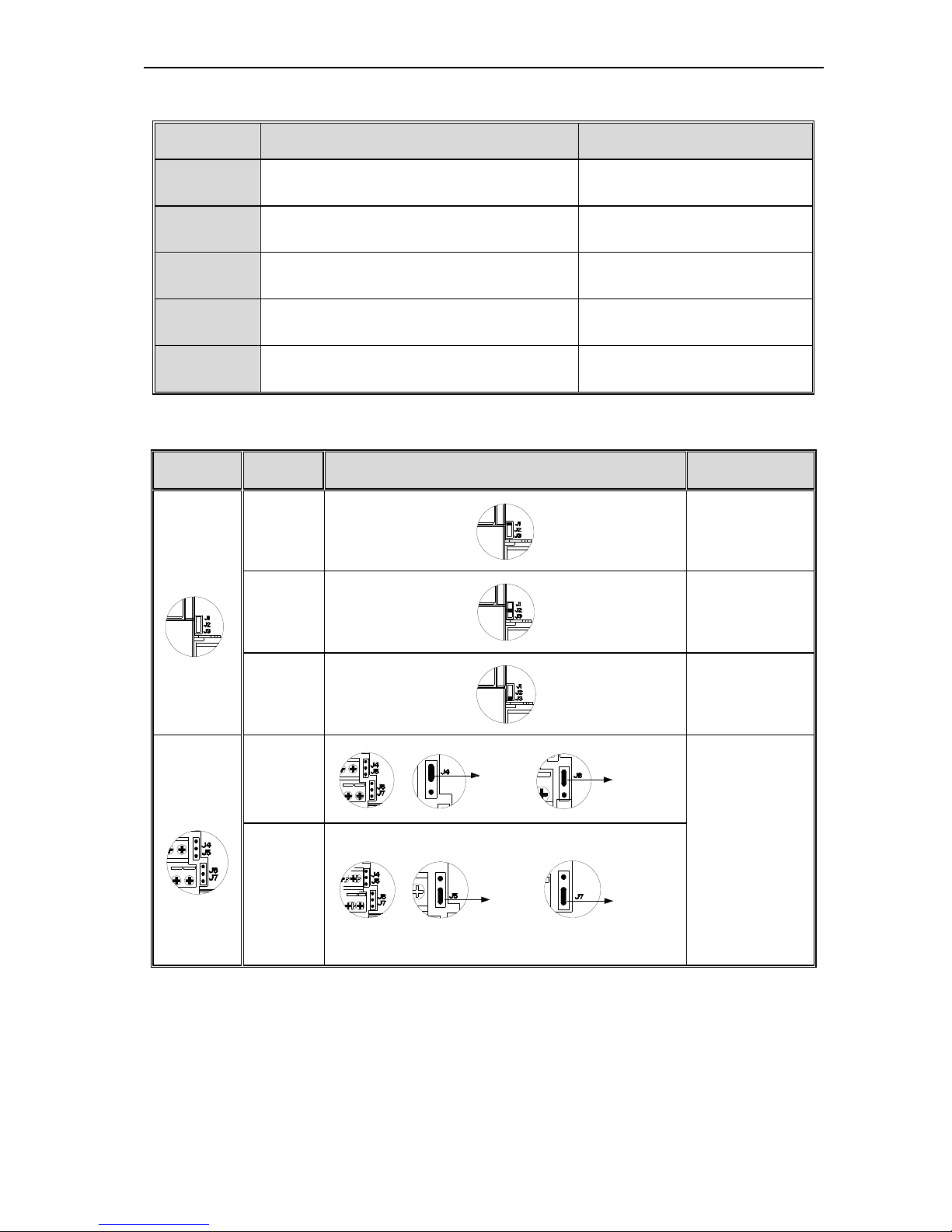
● Switch terminals connection function specification
Switch
terminal
Selectable
position
Picture example
Function
specification
J1
0.2--50kHz
frequency output
J2
0--20mA current
output
4--20mA current
output
J3
0--10V voltage
output
J4 J6
J4 connect
J6 connect
Out track selection
J4 J6 (with PG
card ) Inner
track selection J5
J7 (without PG
card)
J5 J7
J 5 connect
J 7 connect
Chart 3-5:AC90 series inverter switch terminal connection function specification
AC90 TENSION CONTROL FREQUENCY INVERTER MANUAL BASIC OPERATION AND TRIAL RUN
23
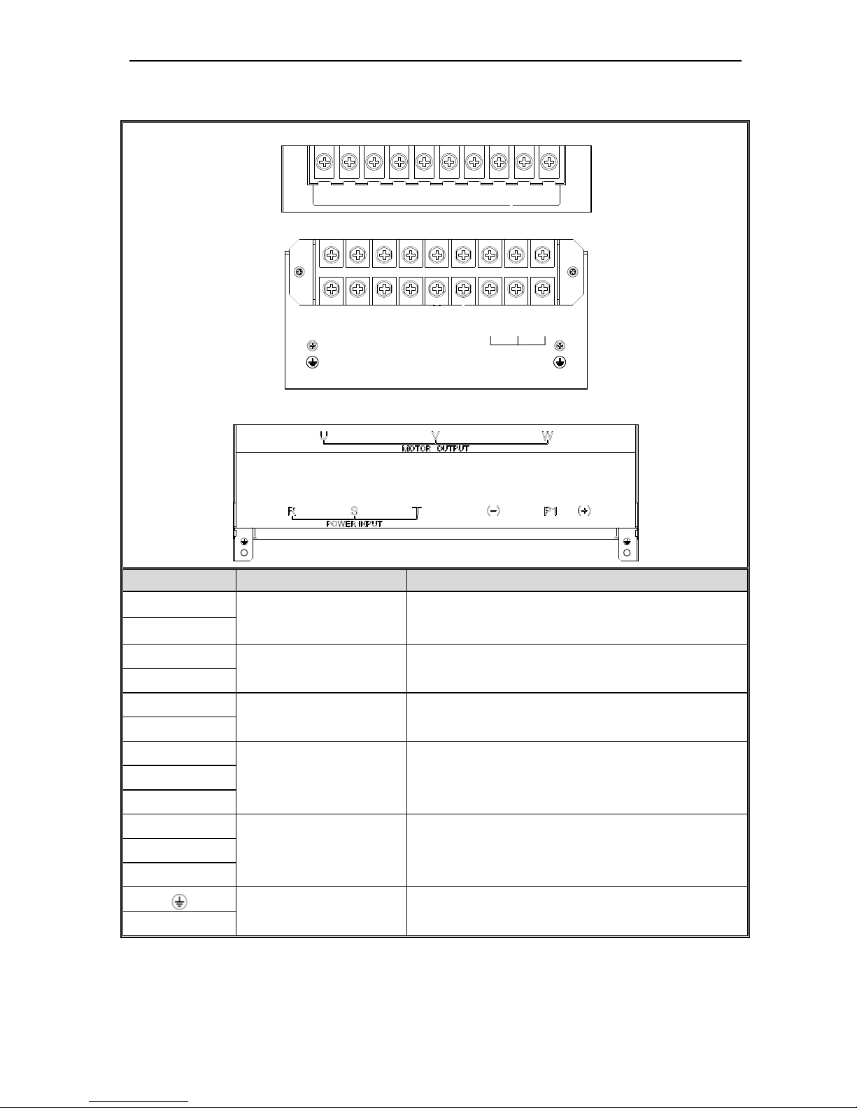
Main circuit terminals
● Main circuit terminals array and definition
Power under 18.5kW main circuit terminals array:
(-)
TSR
PB
UWV
(+)
E
Power under 22~110kW main circuit terminals array:
TSR
P1
UWV
(-)(+)
MOTOR OUTPUT
Power under 132~560kW main circuit terminals array:
Terminal Name Function definition
(-)
DC power terminal
DC power output, (-) means DC bus cathode, (+) means DC
bus anode, used for external braking unit.
(+)
(+)
Braking resistance terminal Used for external braking resistance to realize quick stop.
PB
P1
DC reactor terminal Used for external DC reactor.
(+)
R
Inverter input terminal Used to connect 3-phase AC power supply. S
T
U
Inverter output terminal Used to connect the motor. V
W
Earth Earth terminal, earth resistance<10 OHM
E
Chart 3-6:AC90 series inverter main circuit terminals array and definition
AC90 TENSION CONTROL FREQUENCY INVERTER MANUAL BASIC OPERATION AND TRIAL RUN
24
● 3-phase 380V machine main circuit wiring
Model
Main circuit terminals screw
specifications
Suggested fixed moment
(N·m)
Suggested Copper-core
cable specification mm2
AC90-T3-R75T M4 1.2--1.5 1.5mm2(14)
AC90-T3-1R5T M4 1.2--1.5 2.5mm2(12)
AC90-T3-2R2T M4 1.2--1.5 2.5mm2(12)
AC90-T3-004T M4 1.2--1.5 4mm2(10)
AC90-T3-5R5T M4 1.2--1.5 6mm2(9)
AC90-T3-7R5T M5 2--2.5 6mm2(9)
AC90-T3-011T M5 2--2.5 10mm2(7)
AC90-T3-015T M6 4--6 10mm2(7)
AC90-T3-018T M6 4--6 16mm2(5)
AC90-T3-022T M8 8--10 16mm2(5)
AC90-T3-030T M8 8--10 25mm2(3)
AC90-T3-037T M8 8--10 25mm2(3)
AC90-T3-045T M8 8--10 35mm2(2)
AC90-T3-055T M10 11--13 35mm2(2)
AC90-T3-075T M10 11--13 50mm2(1)
AC90-T3-090T M10 11--13 50mm2(1/0)
AC90-T3-110T M10 11--13 70mm2(2/0)
AC90-T3-132T M10 11--13 95mm2(3/0)
AC90-T3-160T M12 14--16 95mm2(4/0)
AC90-T3-185T M12 14--16 120mm2
AC90-T3-200T M14 17--20 150mm2
AC90-T3-220T M14 17--20 150mm2
AC90-T3-250T M16 20--23 185mm2
AC90-T3-280T M16 20--23 185mm2
AC90-T3-315T M16 20--23 240mm2
AC90-T3-355T M16 20--23 240mm2
AC90-T3-400T M16 20--23 300mm2
AC90-T3-450T M16 20--23 400mm2
AC90-T3-500T M16 20--23 400mm2
AC90-T3-560T M16 20--23 500mm2
Note: Here we suggest to use copper joins as mains electric connectors of machine over 185KW. Pls refer the cut
section area above.
Chart 3-7: Suggested cable diameter and fixed moment 3-phase 380V machine main circuit
AC90 TENSION CONTROL FREQUENCY INVERTER MANUAL BASIC OPERATION AND TRIAL RUN
25
● Single-phase 220V machine main circuit wiring
Model
Main circuit terminals
screw specifications
Suggested fixed
moment (N·m)
Suggested Copper-core
cable specification mm2
AC90-S2-R40T M4 1.2--1.5 1.5mm2(14)
AC90-S2-R75T M4 1.2--1.5 2.5mm2(12)
AC90-S2-1R5T M4 1.2--1.5 2.5mm2(12)
AC90-S2-2R2T M4 1.2--1.5 4mm2(10)
Chart 3-8: Suggested cable diameter and fixed moment single-phase 220V machine main circuit
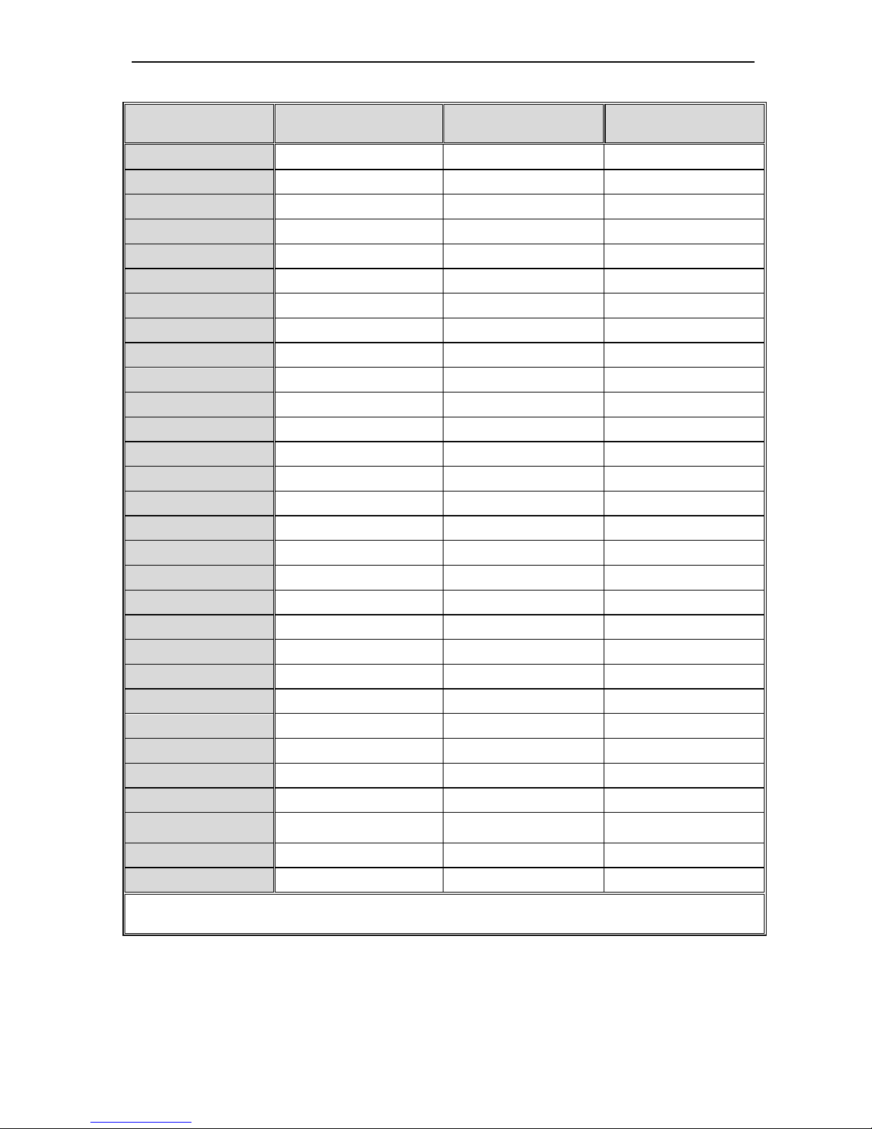
● Suggested main circuit components specification
Model
Contactor
specification
Breaker
specification
DC reactor Input filter Output filter
AC90-T3-R75T 10A 10A ------ NFI-005 NFO-010
AC90-T3-1R5T 10A 10A ------ NFI-005 NFO-010
AC90-T3-2R2T 16A 15A ------ NFI-010 NFO-010
AC90-T3-004T 16A 20A ------ NFI-010 NFO-010
AC90-T3-5R5T 25A 20A ------ NFI-020 NFO-020
AC90-T3-7R5T 25A 30A ------ NFI-020 NFO-020
AC90-T3-011T 32A 40A ------ NFI-036 NFO-036
AC90-T3-015T 40A 50A ------ NFI-036 NFO-036
AC90-T3-018T 50A 60A ------ NFI-050 NFO-050
AC90-T3-022T 50A 75A DCL-50 NFI-050 NFO-050
AC90-T3-030T 63A 100A DCL-80 NFI-080 NFO-080
AC90-T3-037T 80A 125A DCL-100 NFI-100 NFO-100
AC90-T3-045T 100A 150A DCL-110 NFI-100 NFO-100
AC90-T3-055T 125A 175A DCL-125 NFI-150 NFO-150
AC90-T3-075T 160A 200A DCL-150 NFI-150 NFO-150
AC90-T3-090T 220A 250A DCL-200 NFI-200 NFO-300
AC90-T3-110T 220A 300A DCL-200 NFI-200 NFO-300
AC90-T3-132T 250A 400A DCL-300 NFI-300 NFO-300
AC90-T3-160T 300A 500A DCL-300 NFI-300 NFO-300
AC90-T3-185T 400A 600A DCL-400 NFI-400 NFO-400
AC90-T3-200T 400A 700A DCL-400 NFI-400 NFO-400
AC90-T3-220T 630A 800A DCL-500 NFI-600 NFO-600
AC90-T3-250T 630A 1000A DCL-600 NFI-600 NFO-600
AC90-T3-280T 630A 1200A DCL-600 NFI-600 NFO-600
AC90-T3-315T 630A 1200A DCL-800 ------ ------
AC90-T3-355T 800A 1400A DCL-800 ------ ------
AC90-T3-400T 1000A 1600A DCL-1000 ------ ------
 Loading...