

Veichi AC70T-T3-R75-B, AC70T-T3-037-B, AC70T-T3-1R5-B, AC70T-T3-2R2-B, AC70T-T3-004-B User Manual
...

AC70T Crane Purpose VFD Manual
I
CONTENTS
CONTENTS................................................................................................................................I
CHAPTER1OVERVIEW............................................................................................................1
1.1 SAFETYREQUIREMENTANDCAUTIONS......................................................................................1
1.2 BEFOREUSE.........................................................................................................................2
1.3 TECHNICALCRITERION............................................................................................................2
1.4 PRODUCTFEA TURES..............................................................................................................4
CHAPTER2INSTALLA TION.......................................................................................................6
CHAPTER3KEYBOARDLAY O UTANDFUNCTIONSSPECIFICATION........................................13
CHAPTER4FUNCTIONPAR AME T E R TABLE...........................................................................15
4.1 LIFTINGSPECIALPARAME T E RGROUP......................................................................................15
4.2 BASICPAR A M ETER SGROUP...................................................................................................19
4.3 RUNCONTROLPA R A MET E RS.................................................................................................21
4.4 DIGIT ALTERMINALPARA M E T ERGROUP...................................................................................23
4.5 ANALOGTERMINALPAR A MET E R GROUP.................................................................................25
4.6 SYSTEMPAR A METE R GROUP.................................................................................................29
4.7 MOTORPAR A METE R GROUP.................................................................................................32
4.8 MOTORVCPARAM E T E RGROUP............................................................................................33
4.9 MOTORV/FCONTROLPAR A M ETE R ........................................................................................35
4.10 PROTECTIONANDMALFUNCTIONPA R A METE R GROUP...............................................................36
4.11 MULTI‐SPEEDANDPL CFUNCTIONPAR AME T E RGROUP.............................................................41
4.12 COMMUNICAT IONCONTROLFUNCTIONPAR AMET E R GROUP......................................................43
4.13 FAC TORYPAR AME T E RS CORRESPONDINGTOINDUSTRYAPPL ICATIONMACROS...............................45
4.14 LIFTINGMECHANISMDEDICATEDMACRO................................................................................45
4.15 LIGHTLOADSPEEDUPFUNCTION...........................................................................................54
4.16 MULTI‐SPEEDSETTINGINSTRU CTIONS .....................................................................................55
4.17 TERMINALINPUTANDOUTPUTFUNCTIONSELECTION...............................................................56
4.18 MONITORCODE..................................................................................................................58
CHAPTER5FA ULT DIAGNOSESAND TREA TMENTMEASURES...............................................60

AC70T Crane Purpose VFD Manual
II
5.1 FAULTTYPES.......................................................................................................................60
5.2 FAULTINFORMATION...........................................................................................................60
5.3 FAI LURE WARNING..............................................................................................................65
CHAPTER6SELECTIONOFRECOMMENDEDACCESSORIES ...................................................66
6.1 SELECTIONOFBRAKERESISTANCE...........................................................................................66
6.2 SELECTIONOFPGCARD.......................................................................................................66
6.3 INSTRUCTIONOFCLOSE‐LOOPCONTROLMODE........................................................................67
6.4 ENCODERSELECTIONANDINSTALLATIONGUIDANC E..................................................................67
CHAPTER7PERIODICOVERHAULANDMAINTENANCE........................................................69
7.1 OVERHAUL......................................................................................................................... 69
7.2 MAINTENANCE...................................................................................................................70
APPENDIX:MODBUS COMMUNICATIONPR O TOCOL............................................................71

AC70T Crane Purpose VFD Manual
1
Chapter 1 Overview
1.1 Safety requirement and cautions
Please do totally understand this part before using the inverter.
Warning signs and meanings
This manual has used following signs which means there is an important part of security. While observing against the
rules, there is a danger of injury even death or machine system damage.
Danger: Wrong operation may cause death or large accident.
Caution: Wrong operation may cause minor wound.
Operation requirement
Only professionally trained persons can be allowed to operate the equipment. “Professional trained persons “means
the workers must have experience professional trained skill, and must be familiar with installation, wiring, running and
maintain and can rightly deal with emergency cases in use.
Safety guidance
Warning signs come for your security. They are measures to prevent the operator and machine system from damage.
Please carefully read this manual before using and strictly observe the regulations and warning signs while operating.
●Correct transportation, store, installation, careful operation and maintenance are important for inverter safe operation.
In transport and store process, make sure the inverter is free from impact and vibration. It must be stored where is dry
without corrosive air and conductive dust, and the temperature must be lower than 60℃.
● This product carries dangerous voltage and controls driver machine with potential danger. If you don’t abide by the
regulations or requirements in this manual, there is danger of body injury even death and machine system damage.
● Do not wire while the power is connected. Otherwise, there is danger of death for electric shock. Before wiring,
inspection and maintenance, please cut off power supply of all related equipment’s and ensure main DC voltage in
safe range. And please operate it after 5 mins.
● Power wire, motor wire and control wire should be all connected firmly. Earth must be reliable and earth resistance
must be lower than 10Ω.
● Human body electrostatic will damage inner sensitive components seriously. Before operation, please follow ESD
measures. Otherwise, there is danger of inverter damage.
● Inverter output voltage is pulse wave. If components such as capacitor which improves power factor and
pressure-sensitive resistance for anti-thunder and so on are installed at the output side, please dismantle them or
change to input side.
● No switch components such as breaker and contactor at the output side (If there must be one, please make sure the
output current is 0 while the switch acting).
● No matter where the fault is, there is danger of serious accident. So there must be additional external prevent
measures or other safety devices.
●Only used in application fields as maker stated. No use in equipments related to special fields such as emergency,
succor, ship, medical treatment, aviation, nuclear and etc.
● Only Veichi Electric co., ltd service department or its authorized service center can maintain the products. It may
cause product fault while using accessories not authorized or permitted. Any defective components must be
changed in time in maintenance.
AC70T Crane Purpose VFD Manual
2
1.2 Before Use
On receiving your order, please check the package and confirm intact before opening, and check if there’s any
damage, scratch or dirt (damages caused during transportation are not within the company's warranty). If there’s any
damage caused during transportation, please contact us or the transport company immediately. After confirming the
receipt of the goods intact, please re-confirm if the product and your order are consistent.
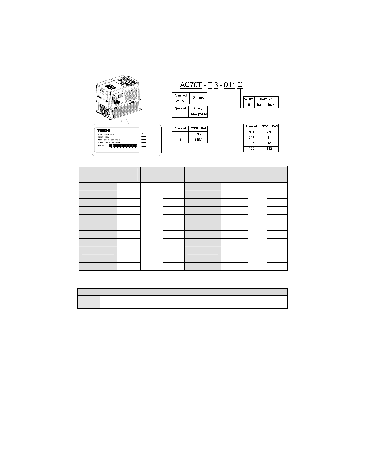
Model
Applicable
motor
Input
VOLT
Rated
Current
Model
Applicable
motor
Input
VOLT
Rated
Current
AC70T-T3-R75-B 0.75KW
3 Phase
380VAC
2.3A
AC70T-T3-037-B 37KW
3 Phase
380VAC
75A
AC70T-T3-1R5-B 1.5KW 3.7A AC70T-T3-045-B 45KW 90A
AC70T-T3-2R2-B 2.2KW 5A AC70T-T3-055-B 55KW 120A
AC70T-T3-004-B 4KW 10A AC70T-T3-075-B 75KW 150A
AC70T-T3-5R5-B 5.5KW 13A AC70T-T3-090-B 90KW 180A
AC70T-T3-7R5-B 7.5KW 17A AC70T-T3-110 110KW 210A
AC70T-T3-011-B 11KW 25A AC70T-T3-132 132KW 250A
AC70T-T3-015-B 15KW 32A AC70T-T3-160 160KW 310A
AC70T-T3-018-B 18KW 38A AC70T-T3-185 185KW 340A
AC70T-T3-022-B 22KW 45A AC70T-T3-200 200KW 380A
AC70T-T3-030-B 30KW 60A
1.3 Technical criterion
Items Criterion
Power
input
Voltage,frequency Three phase 380V 50/60Hz ;
Allowable fluctuations
voltage unbalance rate:<3%; Frequency:±5%; aberration rate: as IEC61800-2
Input
Inverter Model
Output
Power Level
Series No.

AC70T Crane Purpose VFD Manual
3
Inrush current Lower than rated current
Power factor ≥0.94(with DC reactor)
Efficiency ≥96%
Output
Output voltage Output under rated condition: 3 phase, 0~input voltage, inaccuracy<5%
Output frequency
G type:0~600Hz
Output frequency
Max frequency ±0.5%
Overload capacity
G type: 150% rated current/1 min, 180% rated current/10s, 200% rated
Main
Control
performa
nce
Steady speed accuracy V/F without PG , VC without PG, V/F with PG, VC with PG
Starting torque Optimized SVPWM mode
Steady speed accuracy
0.7~16.0kHz
Starting torque VC without PG: rated load 1:100; VC with PG: rated load 1:1000
Steady speed accuracy
VC without PG: ≤2% rated synchronized speed; VC with PG: ≤0.05% rated
Starting torque
VC without PG: when 0.5Hz, 150% rated torque; VC with PG: when 0Hz,
Torque response VC without PG: ≤20ms; VC with PG: ≤10ms
Frequency accuracy Digit setting: max frequency×±0.01%; Analog setting: max frequency×±0.2%
Frequency resolution Digit setting: 0.01Hz; Analog setting: max frequency×0.05%
Basic
functions
DC braking capacity
Starting frequency:0.00~50.00Hz; Braking time:0.0~60.0s; Braking
Torque boost capacity Auto torque upgrade 0.0%~100.0%; Manual torque upgrade 0.0%~30.0%
V/F curve
4 modes: one linearity torque characteristic curve ,one self-setting V/F curve
mode, one drop torque characteristic curve (1.1- 2.0 powers),and square V/F
Acceleration/Decelerati
on curve
2 modes: linear Acceleration/Deceleration and S curve
Acceleration/Deceleration. 4 sets of ACC/DEC, time unit 0.01s selectable,
Rated output voltage
Rely on power supply voltage compensate function, while motor rated voltage
is 100%, set it at the range of 50-100%(output can not over input voltage).
Voltage While power supply voltage fluctuates, it can auto-keep constant output
Auto energy-saving
running
While under V/F control mode, according to load situation, auto-optimize
output voltage to save energy.
Auto-limit current Auto-limit the current while running to prevent over current break trouble.
Instant power off
While instant power off, realize continual operation by bus voltage control.
Standard functions
PID control, speed track, power off restart, jump frequency, upper/lower
frequency limit control, program operation, multi- speed, RS485, analog
Frequency setting
channels
Keyboard digital setting, Analog voltage/current terminal AI1, Analog
voltage/current terminal AI2, Communication given and multi-channel terminal
selection, Main and auxiliary channel combination, expansion card, supporting
Feedback input
channel
Voltage/Current Terminal AI1, Voltage/Current Terminal AI12, Communication
given, Low-speed pulse input PUL, extension card
Running command Operation panel given, external terminal given, communication given,
Input command signal
Start, stop, FWD/REV, JOG, multi-step speed, free stop, reset, ACC/DEC time
selection, frequency given channel selection, exterior fault alarm.
Exterior output signal
1 relay output, 1 collector output, 1 AO output: 0~10V output or 4~20mA
output, or frequency pulse output
Protection function
Overvoltage, under-voltage, current limit, over-current, overload, electric
thermal relay, overheat, overvoltage stall, data protection, rapid speed
Keyboar LED display Single file 5 digital tube display Can monitor one state variable

AC70T Crane Purpose VFD Manual
4
d
display
Two file 5 digital tube display Can monitor two state variables
Parameter copy
Can upload or download function code information of inverter to realize fast
State monitor
Output frequency, given frequency, output current, input voltage, output
voltage, motor speed, PID feedback, PID given value, module temperature
Fault alarm
,Over-voltage, under-voltage, over-current, short circuit, phase failure,
overload, overheat, overvoltage stall, current limit, or data protection
Environ
ment
Install place
altitude ≤ 1000m,above 1000m down the rated amount, each increase of
100m down the rated amount of 1%;no condensation, ice ,rain, snow, hail;
solar radiation below 700W/㎡, air pressure 70-106 kPa
Temperature, humidity
-10~+50℃, above 40℃ down the rated amount, the max temperature:60℃
Vibration
9~200Hz,5.9m/s2(0.6g)
Store temperature -30—+60℃
Installation Hanging type, cabinet type
Protection degree IP20
Cooling mode Forced air cooling
1.4 Product Features
1. Special VFD for lifting: high working efficiency, fast response, good speed regulation performance, stable
operation, no impact and high safety factor.
2. Stall protection function (closed-loop mode): When the actual speed is detected to exceed 115% of the rated
speed during operation, the frequency inverter signal sends a brake signal to achieve emergency braking.
3. Anti-slip protection function (closed loop mode): In the closed loop mode, when the inverter is energized in the
standby state, when the motor is detected to rotate, the function is activated immediately, and the inverter is locked at
the zero speed output, which provides the system operation. It has maximum security.
4. Zero servo hover function (closed loop mode): that is, at zero speed, keeping the brake open and keeping the
lifting mechanism hovering in the air.
5. Full-range torque monitoring function: Torque monitoring during operation, when the torque output is detected,
immediately block the output and achieve emergency stop.
6. Remote monitoring module (extension): realizes remote positioning, online monitoring, remote fault diagnosis
and other functions of mechanical equipment; provides customers with a wider range of value-added services.
7. Light-load high-speed function: When running in the light load or empty hook state, the frequency is
automatically increased (constant power zone) through the built-in load measurement mode calculation, effectively
improving the working efficiency of the lifting machine by 10% to 50%.
8. Output abnormal protection: torque monitoring during operation, when the torque output is detected or no load,
immediately block the output and achieve emergency stop.
9. The rotary operation is stable: the low-speed operation is smooth and coherent, there is no stop-and-go
phenomenon, the gear position is stable, the boom is continuous and smooth, and there is no “pause” phenomenon.
10. Rotary eddy current control: The built-in eddy current controller adopts PWM pulse width modulation to adjust
the output voltage duty ratio in real time according to the operating frequency, which is superior to the traditional eddy
current voltage regulation module.
11. Flexible torque control (slewing): The “soft belt” is powerful and fast, and the boom does not rebound smoothly.
12. Anti-sway function (variable): The swing is limited by dynamically adjusting the frequency of the inverter and the
acceleration/deceleration time. When the object reaches the set speed, the swing is small or basically stops when it
stops.
13. Special brake logic control: realize the special brake logic control through the release frequency, release current,
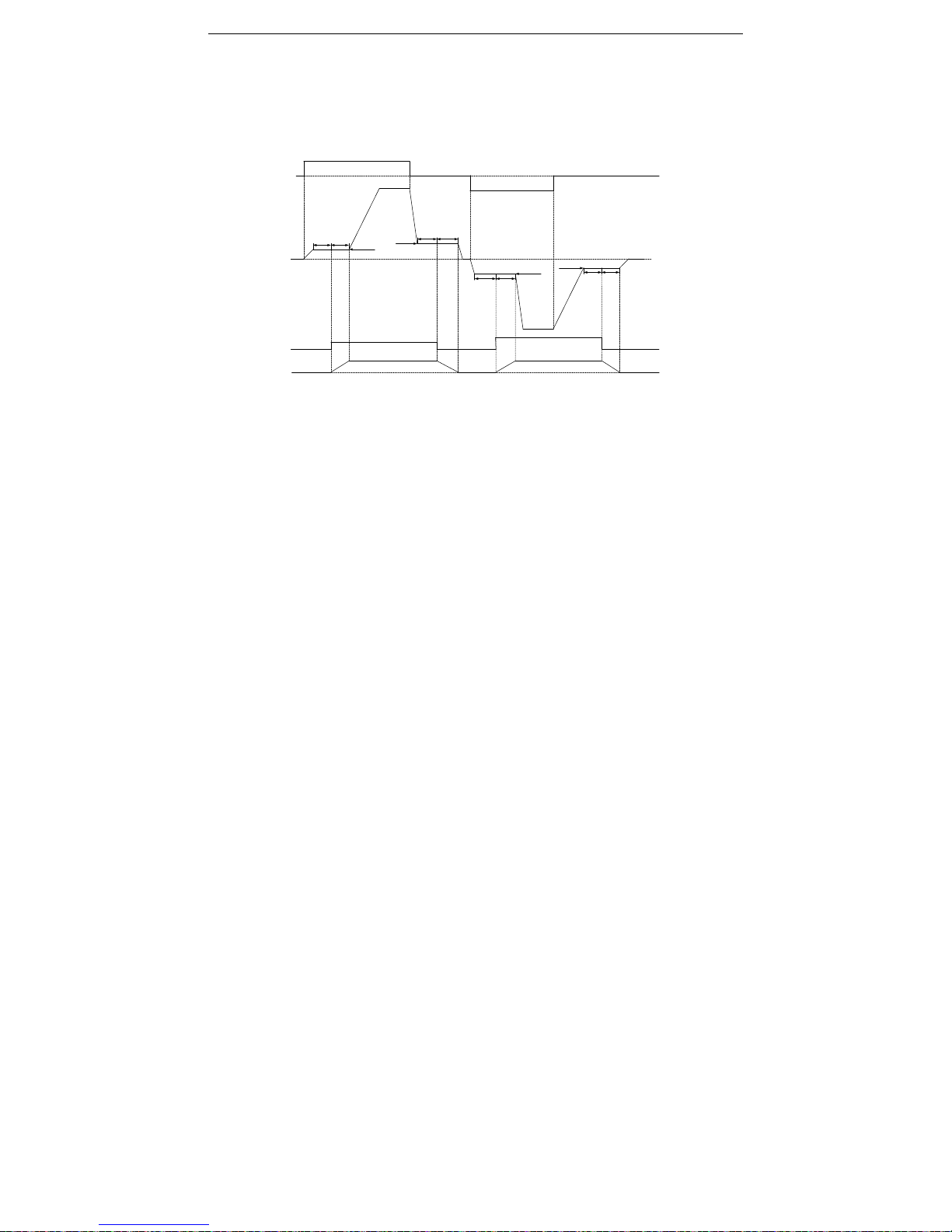
AC70T Crane Purpose VFD Manual
5
brake release time, brake holding time, etc., to ensure the system is safe and reliable.
14. Brake timing description: When the brake is not energized, it is in the state of holding the brake, and must be
released under the condition that the brake is energized; through the release frequency, release current, brake
release time, brake holding brake Time, etc., to achieve a dedicated brake logic control to ensure that the system is
safe and reliable to avoid slipping.
Operatio n
signal
Output
frequency
Brake
signal
Brake
motion
FWD
Up-operation frequency
FF.10 FF.11
FF.06 Release frequency
FF.07 Brake
frequency
FF.12 FF.13
FF.14 FF.15
FF.08 Release
frequency
FF.09 Brake frequency
FF.16 FF.17
ON
ON
OFF
OFF
Down-operation frequency
ON
ON
REV
AC70T Crane Purpose VFD Manual
6
Chapter 2 Installation
This section specifies the considerations necessary for reliable and safe operation of the product by users.
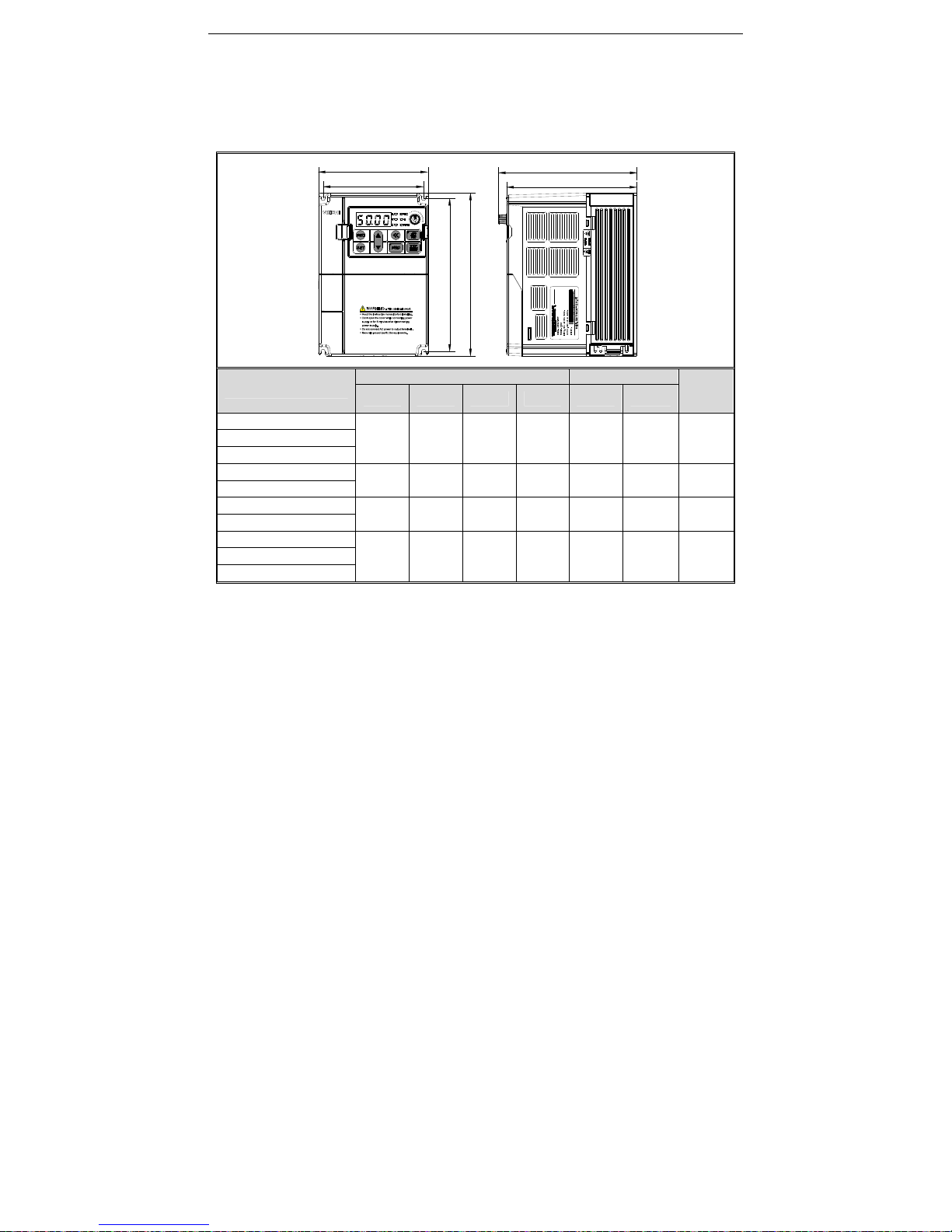
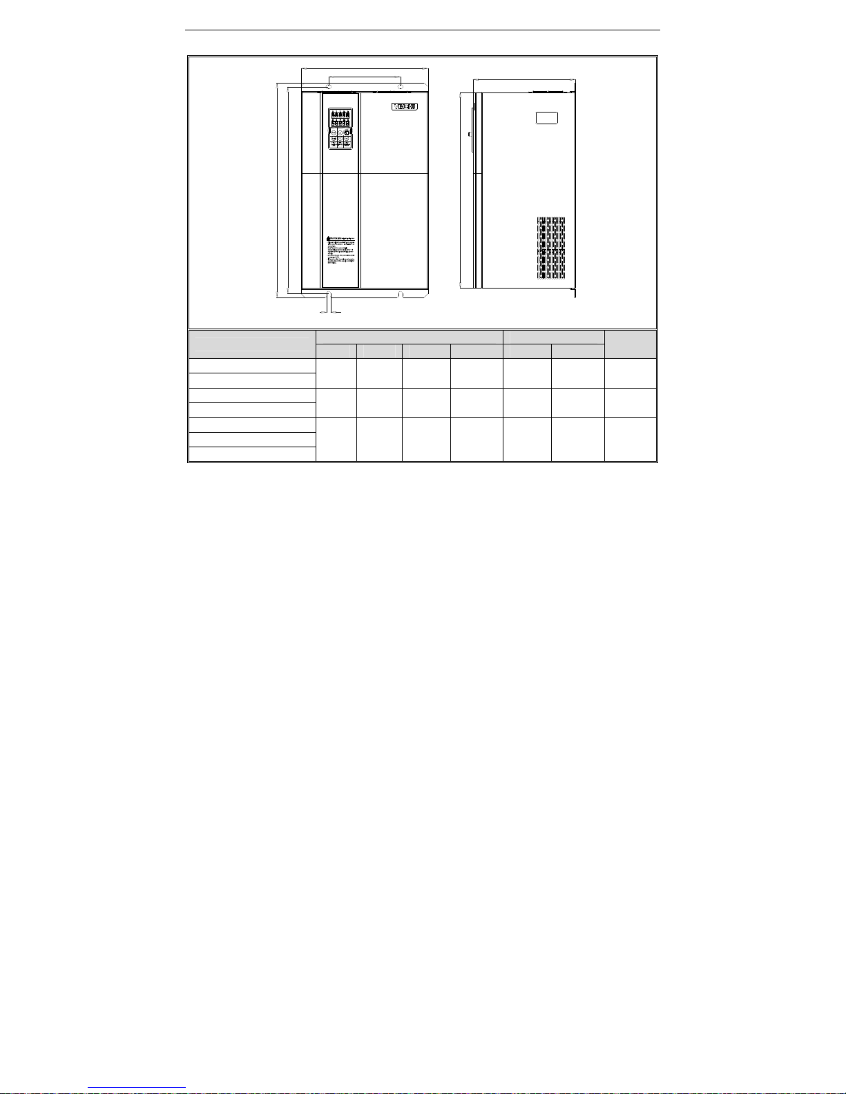
Overall Dimension of Inverter (Plastic)
W
W1
D
D1
H
H1
Model
Overall Dimension Instillation Position
INSTALLATION
APERTURE
W H D D1 W1 H1
AC70T-T3-R75-B
122 182 154.5 145 112 171 ф5
AC70T-T3-1R5-B
AC70T-T3-2R2-B
AC70T-T3-004-B
159 246 157.5 148 147.2 236 ф5.5
AC70T-T3-5R5-B
AC70T-T3-7R5-B
195 291 167.5 158 179 275 ф7
AC70T-T3-011-B
AC70T-T3-015-B
230 330 200 190 208 315 ф7
AC70T-T3-018-B
AC70T-T3-022-B
AC70T Crane Purpose VFD Manual
7
W
W1
D
H
H1
H2
安装孔径
Model
Overall Dimension Instillation Position
INSTALLATION
APERTURE
W H D H2 W1 H1
AC70T-T3-030-B
255 410 225 370 180 395 Ф7
AC70T-T3-037-B
AC70T-T3-045-B
305 570 260 522 180 550 Ф9
AC70T-T3-055-B
AC70T-T3-075-B
380 620 290 564 240 595 ф11 AC70T-T3-090-B
AC70T-T3-110
Installation aperture
AC70T Crane Purpose VFD Manual
8
H1
H
H2
D
W1
W
Model
Overall Dimension Instillation Position INSTALLATI
ON
W H D H2 W1 H1
AC70T-T3-132 500 780 340 708 350 755 ф11
AC70T-T3-160
650 1060 400 950 400 1023 ф16
AC70T-T3-185
AC70T-T3-200
AC70T Crane Purpose VFD Manual
9
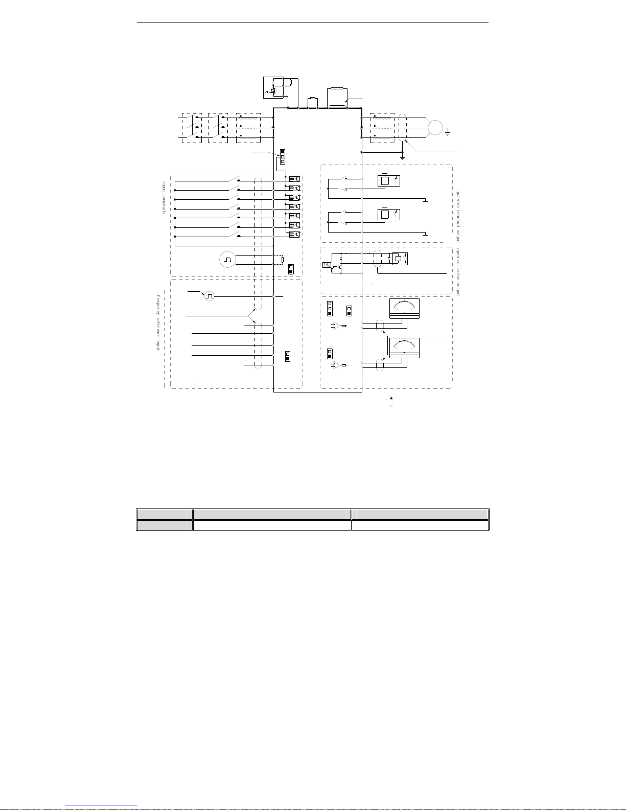
Standard Connection Diagram
● Standard Connection Diagram
Note: 1.When installing DC reactor, make sure to dismantle the short connector between terminal P1 and(+).
2.NPN or PNP transistor signal can be selected as input of multi-function input terminal(X1~X7/PUL).
Inverter built-in power supply (+24V terminal) or external power supply (PLC terminal) can be chosen as
bias voltage. Factory setting ‘+24V’ short connect with ‘PLC’.
3. Analog monitor output is the special output for meters such as frequency meter, current meter and voltage
meter. It can’t be used for control operations such as feedback control.
4. As there are multi pulse styles, please refer to the line connect mode description details.
●
Auxiliary Terminal Output Capacity
Te rm in al Function Definition Max Output
+10V 10V auxiliary power supply output, constitutes loop 50mA
notice 2
notice:default settings in bracket
notice 1
TA1
TB1
TC1
+24V
Y
shielded twisted pair cable
_
mA
2
0
10
0
-
+
0
5
1
0
V
_
+
-
GND
A01
V
W
U
M
~
shielded cables
(near inverter groud )
E
(ground resistor low
than 10
Ω
)
W
V
U
output reactor
DC reactor
brake
resistor
short
circuit
P1
+
( )
R
brake module
voltage model analog input
current model analog input
+10V
R
T
S
AC input
AI
GND
AS
VS
shielded twisted pair line)
input pulse
X7
(reversal jog running)
(forward jog running)
(reversal running)
(forward running)
(free stop)
(fault reset)
(none)
COM
X3
X4
X6
X5
X1
X2
PB
( )
+
(-)
inverter
S
T
R
GND
A02
COM
p
a
s
s
i
v
e
t
e
r
m
i
n
a
l
o
u
t
p
u
t
AC220V
AC0V
K3
K4
max output
3A/240VAC
5A/30VDC
1 +24Vmax output:DC24V/100mA
A01/A02 used as frequency or
voltage output
,max current
2mA
2 VS/AIterminal resistor:75K
Ω
1.+10V terminals max input 50mA
notice:
2 Y max output:DC24V/50mA
notice:
2
stand for control circuit terminal
notice:
stand for main circuit terminal
1
shielded twisted pair
cable(near inverter ground)
input reactorconnector
circuit
breaker
(
0~5V
)/(
0~10V
)
(
0~20mA
)/(
4~20mA
)
3 AS terminal resistor:250
Ω
notice:
+
( )
notice 4
PUL
X7
PUL
+24V
PLC
COM
current/voltage analog input
J1
J2
J3
K1
K2
K5
K6
TA2
TB2
TC2
AC220V
AC0V
o
p
e
n
c
o
l
l
e
c
t
o
r
o
u
t
p
u
t
A+
B-
RS485 communication
120
Ω
K7
K8
analog output monitor
i
n
p
u
t
t
e
r
m
i
n
a
l
s
f
r
e
q
u
e
n
c
y
r
e
f
e
r
e
n
c
e
i
n
p
u
t
AC70T Crane Purpose VFD Manual
10
A0 Analog monitor output, constitutes loop with GND.
Max output 2mA as frequency, voltage
+24V
24V auxiliary power supply output, constitutes loop
100mA
Y
Collector open circuit output; can set the
action-object by program.
DC24V/50mA
TA/ TB /T C
Passive connector output; can set the action-object
by program.
3A/240VAC
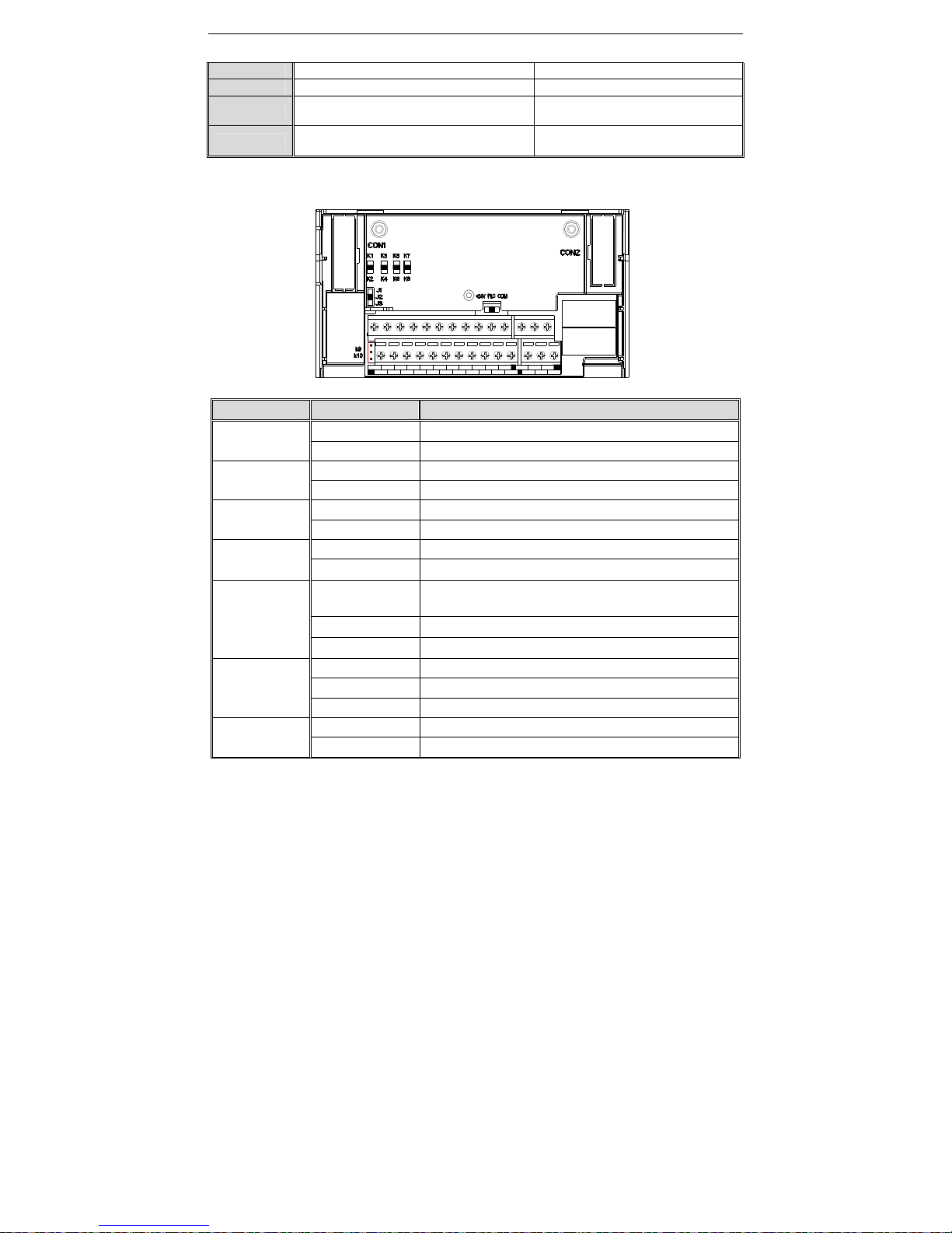
● Connection Function Specification of Switch Terminals
Switch Terminal Selecting Position Function Specification
S1
K1 AO1:0~20mA or 4~20mA current output
K2 AO1:0~10V voltage output
S2
K3 AI:0~20mA or 4~20mA input current
K4 AI: 0~10V input voltage
S3
K5 AO2: 0.0~100kHz (J1 on), open collector circuit output
K6 AO2:0.0~100kHz (J1 on), active source output
S4
K7 RS485: connect with 120Ω terminal resistor
K8 RS485:connect without 120Ω terminal resistor
S5
J1
AO2:0.0~100kHz frequency output(PWM eddy current pulse wav
e
output)
J2 AO2:0~20mA or 4~20mA current output
J3 0~10V voltage output
S6
+24V Short +24V terminal and PLC terminal
PLC PLC terminal receiving external power input
COM Short PLC terminal and COM terminal
S7
K9 Disconnect GND terminal and PE discharge loop
K10 Connect GND terminal and PE discharge loop
AS
VS GND
GNDAO2 AO1
X1
X2
AI +1 0V COM
TC1
PLC TA1
A+ +24V
X7/PULX4X3
X5
TB2X6
TA2
B- Y
TB1
COM TC2
AC70T Crane Purpose VFD Manual
11
Multi-functional Contact Input Connection
● NPN transistor connection mode
Use inner 24V power
+24V
PLC
X1
X2
X4
X3
X7
X6
X5
COM
shielded cable
E
(factory short connect)
E
COM
X5
X6
X7
X3
X4
X2
X1
PLC
+24V
Use innner 24V power
exterior
control
signal
exterior
control
signal
shielded cable
Note:Disconnect '+24V'with'PLC' when using exterior power
exterior 24V power
+
-
+24V
PLC
COM
+24V
PLC
COM
PUL PUL
inverter inverter
NPN Transistor Digital Input Signal Connection Mode
● PNP transistor connection mode
-
+
use exterior 24 power
E
X5
X6
X7
X3
X4
X2
X1
PLC
+24V
Use inner 24V power
COM
Use inner 24V power
shielded cable
exterior
control
signal
+24V
PLC
COM
PUL
inverter
+24V
PLC
COM
exterior
control
signal
shielded cable
E
X5
X6
X7
X3
X4
X2
X1
PLC
+24V
COM
PUL
inverter
PNP Transistor Digital Input Signal Connection Mode
Digital output signal connection
shielded twisted
pair cable
COM
winding
E
Y1
+24V
COM
inverter
exterior 24V power
- +
inverter
shield twisted pair cable
winding
COM
Y1
+24V
E
COM
AC70T Crane Purpose VFD Manual
12
Analog Output Signal Connection
shielded twisted pair cable
shielded twisted pair cable
GND
E
AO1
shielded twisted pair cable
-
+
_
V
1
0
5
0
AO2 terminal use as 0~10V output indicator
inverter
AO1 terminal use as 0~10V output indicator
0
5
1
0
V
_
+
-
AO1terminal use as 0~20mA output indicator
0
10
2
0
mA
_
AO2 terminal use as 0.2~50kHz active source pulse output
kHz
5
0
25
0
-
+
+
-
shielded twisted pair cable
AO2 terminal use as 0~20mA output indicator
0
10
2
0
mA
_
-
+
shielded twisted pair cable
K1
K2
K1
K2
J1
J2
J3
J1
J2
J3
shielded twisted pair cable
AO2 terminal use as 0.2~50kHz open collector circuit pulse output
kHz
5
0
25
0
+
-
J1
J2
J3
K5
K6
bias resistor
-
+
exterior power
inverter
inverter inverter
GND
E
AO2
GND
E
AO2
GND
E
AO2
GND
E
AO2
GND
E
AO2
inverter
inverter
J1
J2
J3
K5
K6
Connection of Pulse Input Signal
connection of passive source pulse signal in put
connection of active source pulse signal input
E
COM
PUL
COM
pulse signal source
shielded twisted pair source
inverter
+24V
PLC
COM
X7
PUL
shielded twisted pair source
pulse signal source
PUL
COM
E
COM
X7
PUL
inverter
+24V
PLC
COM
Ch
a
●
Keyb
o
●
Key f
u
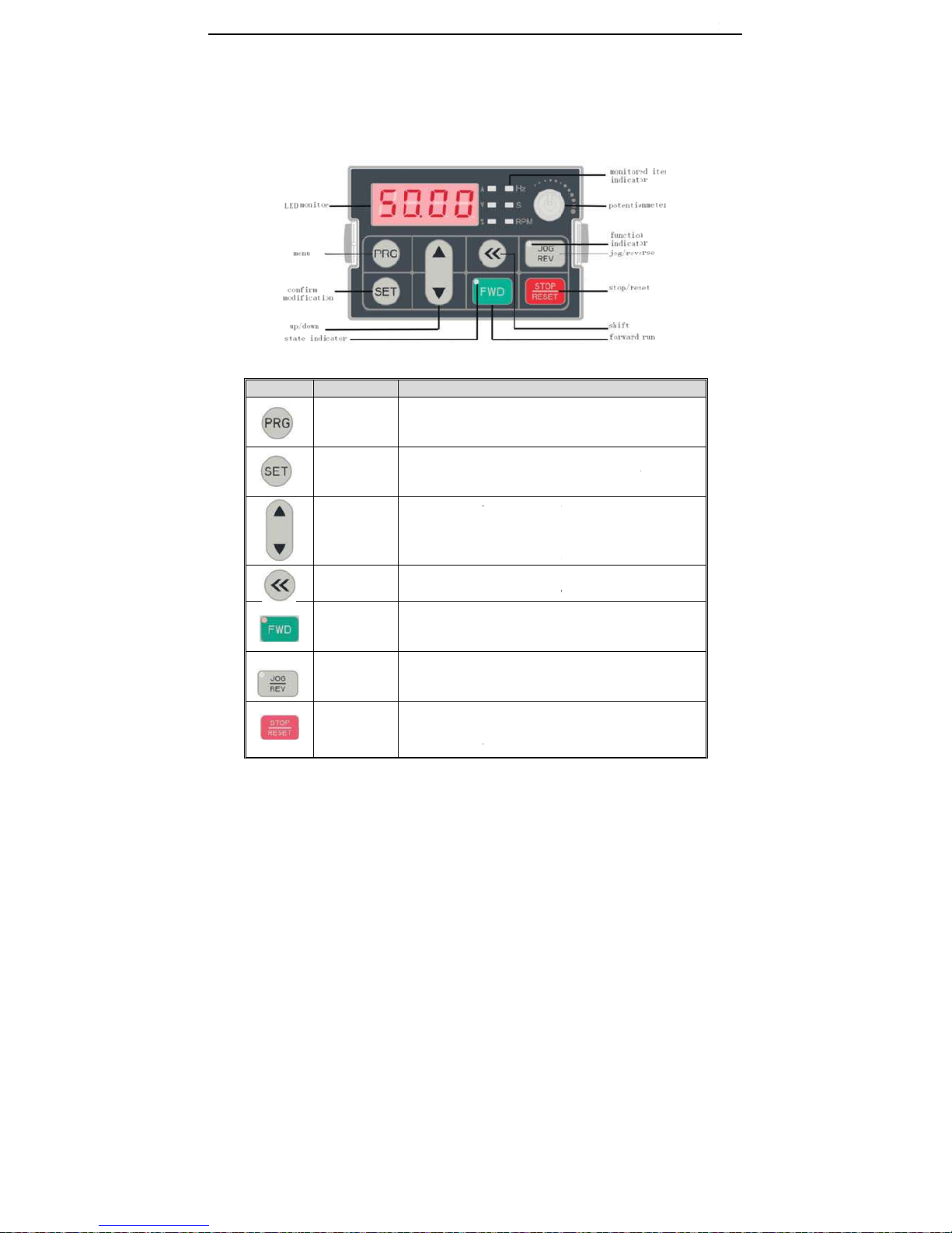
pter 3
K
ard appearance
nction
Key
C
S
eyboard
Name
Menu key
onfirm/modify
key
Up/down key
Shift key
Forward run
key
Jog/reverse
key
top/reset key
13
layout
a
Enter menu whil
e
while modify par
a
sec to enter con
d
Press to modify
p
confirm after mo
d
change LED mo
n
Select paramete
r
modify state. Mo
d
or monitoring sta
t
keyboard and [F
4
Select digit of fun
parameter digits
m
While run/stop is
forward runs, an
d
indicator sparks.
This key can be
d
and indicator is o
f
and indicator is o
n
Machine stops if
p
Its efficiency ran
g
in fault state (no
r
nd func
t
Functi
o
standby or runni
n
meter. While sta
n
ition monitoring i
n
arameter while in
ifying. While stan
d
itoring items at st
o
group in menu in
t
ify given frequen
c
e (While given fr
e
.09] needs to be
s
c
tion No. modifie
d
odified by up/do
w
controlled by key
b
the indicator is a
l
efined by [F4.07]
f if it is defined as
if it is defined as
ress it while run/
s
e is defined by [F
4
eset if fault is not
s
AC70T C
r
ions sp
e
on
g. Press this key
dby or running, p
terface.
menu interface.
P
d
by or running, p
r
op.
terface. Modify p
a
y,PID given whil
e
quency, PID are
s
set.
by up/down key;
w
n key.
oard, press this
k
l
ways on. While r
e
. Press it, machin
e
REVERSE. Mac
h
JOG.
top is controlled
b
4.08]. Inverter re
s
s
olved).
ane Purpose VFD
M
cificatio
n
to return
r
ess for 1
ress again to
ess to
rameter in
at standby
et by
Select
ey, inverter
verse, the
e
reverses
ine will jog
y keyboard.
ets if press it
anual

AC70T C
r
●
Indic
a
r
ane Purpose VFD
M
p
tor light meanin
g
N
a
Unit indicator
light
State
indicator light
Function
indicator light
anual
Keyboard
otentiometer
s
me
Hz
A
V
S
RPM
%
FWD
FWD
FWD
REV/JOG
REV/JOG
14
Can be used as i
n
frequency limit, g
i
State
Spark/On
On
Spark/On
On
On
Spark/On
On
Spark
Off
On
Off
put channel for
g
ven torque, given
Frequency unit
Current unit
Voltage unit
Time un it
Motor speed unit
Percent unit
Forward running
Reverse running
Stop
Jog.
Reverse.
iven frequency, u
PID or PID feed
b
Meaning
pper
ack setting.

AC70T Crane Purpose VFD Manual
15
Chapter 4 Function Parameter Table
This chapter just provides function parameter table. Specifications refer to AC200 technical manual or inquiry the
company.
“●”: Parameter can be changed in the running state.
“〇”: Parameter can’t be changed in the running state.
“×”: Parameter can be read only.
“–”: Factory setting parameter, only factory can set.
“※”: Parameter is related to the model.
Special parameters group
4.1 Lifting special parameter group
NO. Function description Range of settings and definition
Factory
default
Feature Address
FF.00
Application type
selection
0: General
1: hoisting mechanism (closed loop)
2: Translation mechanism
3: Rotating mechanism
4: Construction lift
5: Lifting mechanism (open loop)
5 〇 0xF00
FF.01
Brake mode selection
LED ‘0’ digit: brake release
0: frequency opens
1: frequency and current associated
with opening
LED ‘00’ digit: starting direction
selection
0: The torque is the same as the
running direction
1: The torque is always in the forward
direction
LED ‘000’ digit: stop direction
selection
0: The torque is the same as the
running direction
1: The torque is always in the forward
direction
LED ‘0000’ digit: brake control
frequency jump
0: invalid
1: valid
1001 〇 0xF01

AC70T Crane Purpose VFD Manual
16
FF.02 Run command control
LED ‘0’ digit: reverse control during
operation
0: not allowed to run
1: Allow reverse operation
LED ‘00’ digit: zero-crossing
frequency jump function
0: Invalid 1: Valid
LED ‘000’ digit: Reserved
0010 〇 0xF02
FF.03
Restart waiting delay
during braking
0.00-10.00s 0.30s 〇 0xF03
FF.04
Brake release current
coefficient
10.0-100.0% 30.0% 〇 0xF04
FF.05
Zero crossing
frequency
0.00-10.00Hz 1.00Hz 〇 0xF05
FF.06 Up release frequency 0.00-10.00Hz 2.00Hz 〇 0xF06
FF.07 Up brake frequency 0.00-10.00Hz 2.00Hz 〇 0xF07
FF.08
Down release
frequency
0.00-10.00Hz
2.00Hz
〇 0xF08
FF.09 Down brake frequency 0.00-10.00Hz 2.00Hz 〇 0xF09
FF.10 Delay before the lift 0.00-10.00s 0.20s 〇 0xF0A
FF.11 Delay after the lift 0.00-10.00s 0.10s 〇 0xF0B
FF.12
Delay before the
upward brake
0.00-10.00s 0.00s 〇 0xF0C
FF.13 Delay after the up brake 0.00-10.00s 0.50s 〇 0xF0D
FF.14
Down delay before the
release
0.00-10.00s 0.30s 〇 0xF0E
FF.15
Delay after down
release
0.00-10.00s 0.10s 〇 0xF0F
FF.16 Delay before the brake 0.00-10.00s 0.00s 〇 0xF10
FF.17 Delay after down brake 0.00-10.00s 0.30s 〇 0xF1A
FF.18
-FF.24
Reserved
FF.25
Current judgment
enable during operation
0~1 1 〇 0xF19
FF.26
In-service current
detection
0%~50% 5% 〇 0xF1A

AC70T Crane Purpose VFD Manual
17
FF.27
Running current
detection time
0.000~1.000s 0.400s 〇 0xF1B
FF.28
Light load upscaling
function selection
0: Invalid 1: Judging by current 2:
Judging by weight
0 〇 0xF1C
FF.29
Load measurement
time
0.000~5.000s 1.000s 〇 0xF1D
FF.30
Upward upswing
judg
ment threshold
0.0~80.0% 50.0% 〇 0xF1E
FF.31
Up frequency up
frequency limit
0.00~Max frequency 65.00Hz ● 0xF1F
FF.32
Downward upselling
threshold
0.0~80.0% 50.0% 〇 0xF20
FF.33
Downward frequency
up frequency
0.00~Max frequency 65.00Hz ● 0xF21
FF.34-FF.35 Reserved
FF.36
Rotary flexible control
option
LED ‘0’ digit: rotary flexible control
0: off 1: open
LED ‘00’ digit: flexible control
acceleration and deceleration time
0: off 1: open
LED ‘000’ digit: Reserved
0000 ● 0xF24
FF.37
Flexible control starting
deviation frequency
0.00~20.00Hz 2.50Hz ● 0xF25
FF.38
Flexible control direction
changes deviation
frequency
0.00~20.00Hz 2.50Hz ● 0xF26
FF.39
Flexible control
acceleration time 1
0.00~650.00s 20.00s ● 0xF27
FF.40
Flexible control
deceleration time 2
0.00~650.00s 20.00s ● 0xF28
FF.41
Acceleration/deceleratio
n time 1 switches to the
frequency of
acceleration/deceleratio
n time 2
0.00~Max frequency 0.00Hz ● 0xF29
FF.42
Acceleration/deceleratio
n time 2 switches to the
frequency of
acceleration/deceleratio
n time 3
0.00~Max frequency 0.00Hz ● 0xF2A

AC70T Crane Purpose VFD Manual
18
FF.43
Acceleration/deceleratio
n time 3 switches to
Acceleration/deceleratio
n time 4 frequency
0.00~Max frequency 0.00Hz ● 0xF2B
FF.44 Reserved 0xF2C
FF.45
Eddy current frequency
1
0.00~Max frequency 20.00Hz ● 0xF2D
FF.46
Eddy current frequency
2
0.00~Max frequency 40.00Hz ● 0xF2E
FF.47
Eddy current frequency
3
0.00~Max frequency 40.00Hz ● 0xF2F
FF.48 Zero speed duty cycle 0.00~100.0% 80.00% ● 0xF30
FF.49
Eddy current frequency
1 corresponds to duty
cycle
0.00~100.0% 40.00% ● 0xF31
FF.50 Maximum duty cycle 0.00~100.0% 80.00% ● 0xF32
FF.51
Stop vortex
maintenance time
0.0~3000.0S 60.00s 〇 0xF33
FF.52
Eddy current output
carrier
0.20-4.00kHz 2.00kHz 〇 0xF34
FF.53
Duty cycle polarity
selection
0: Invalid 1: Valid 1 〇 0xF35
FF.54
Shutdown duty cycle
change rate
0.0%/100ms 1.0ms ● 0xF36
FF.55 Brake failure detection 0: Invalid 1: Valid 0 〇 0xF37
FF.56
Brake failure detection
times
0~10 3 〇 0xF38
FF.57
Brake failure detection
torque
0.0~150.0% 100.0% 〇 0xF39
FF.58
Brake failure detection
frequency threshold
0.00~5.00Hz 1.00Hz 〇 0xF3A
FF.59
Brake failure detection
frequency threshold
filtering
0.0~2.000s 0.200s 〇 0xF3B
FF.60
Anti-flow hook function
selection
0: Invalid 1: Valid 0 〇 0xF3C

AC70T Crane Purpose VFD Manual
19
FF.61
Anti-flow hook start
threshold
0.00~5.00Hz 1.00Hz 〇 0xF3D
FF.62
Anti-flow hook
maintenance time
0.0~3000.0s 60.0s 〇 0xF3E
FF.63
Anti-flow hook start
threshold filtering
0.0~2.000s 0.100s 〇 0xF3F
FF.65
-FF.69
Reserved
FF.70
Rotary brake mode
selection
0: electric brake:
1 : power off brake
0 ● 0xF46
FF.72
Encode cable missing
detection
LED ‘0’ digit: A/B phase 0: off 1: on
LED ‘00’ digit: Z phase 0: off 1: on
0001
4.2 Basic parameters group
NO. Function description Range of settings and definition
Factory
default
Feature Address
F0.00 Motor control mode
Asynchronous motor control
mode:
0: V/F control
3: High-performance VC without PG
4: High-performance VC with PG
0 〇 0x000
F0.01 Reserved
0x001
F0.02
Run command channel
0: Keyboard control
1: Terminal control
2: RS485 communication control
3: Optional card
0 ● 0x002
F0.03
Frequency given source
channel A
0: Keyboard number given
1: Keyboard potentiometer given
2: VS voltage analog given
3: AI analog given
4: AS current analog given
5: Terminal pulse PUL given
6: RS485 communication given
0 ● 0x003
F0.04
Frequency given source
channel B
1 ● 0x004
F0.05
Frequency channel B
reference source
0: Max. output frequency as
reference source
0 ● 0x005

AC70T Crane Purpose VFD Manual
20
F0.06
Frequency given source
selection
0: Channel A
1: Channel B
2: Channel A+Channel B
3: Channel A-Channel B
4: Max. value of Channel A and
Channel B
5: Min. value of Channel A and
Channel B
0 ● 0x006
F0.07
Running command
binding
LED“0”digit: keyboard command
instruction binding
LED“00”digit: terminal command
instruction binding
LED“000”digit: communication
command instruction binding
LED“0000”digit: optional card
command instruction binding
0 : no binding
1 : keyboard number given frequency
2 : Keyboard potentiometer given
3 : VS voltage analog given
4 : AI current/voltage analog given
5 : AS current analog given
6 : Terminal pulse PUL given
7: RS485 communication given
8 : Terminal UP/DW control
9 : PID control given
A: Program control (PLC) given
B: Optional card
C: Multi-speed given
0000 ● 0x007
F0.08
Keyboard number
setting frequency
0~upper limit
50.00Hz ● 0x008
F0.09 Max frequency output
upper limit~600.00Hz
50.00Hz 〇 0x009
F0.10
Upper limit frequency
source selection
0: Upper limit frequency digital given
1: Keyboard potentiometer given
2: Terminal VS analog given
3:Terminal AI analog given
4: Terminal AS analog given
5: Terminal pulse PUL given
6: RS485 communication given
0 ● 0x00A
F0.11
Upper frequency limit
digital setting
Lower limit frequency~max
frequency
50.00Hz ● 0x00B
F0.12 Lower limit frequency
0.00~upper limit frequency
0.00Hz ● 0x00C
 Loading...