

Veichi AC70-T3-R75G/1R5P, AC70-T3-7R5G/011P, AC70-T3-018G/022P, AC70-T3-015G/018P, AC70-T3-022G/030P User Manual
...

Contents
Chapter1 Overview .............................................................................................................................................. 1
1.1 Safety Requirement and Cautions ............................................................................................................ 1
1.2 Technical Criterion ..................................................................................................................................... 4
Chapter 2 Before Use .......................................................................................................................................... 7
2.1 Purchase Inspection .................................................................................................................................. 7
2.2 Nameplate ................................................................................................................................................. 7
2.3 Rated Output Current ................................................................................................................................ 8
Chapter 3 Installation and Wiring ...................................................................................................................... 9
3.1 Safety Precautions .................................................................................................................................... 9
3.2 Treatment for Inverter after Longtime Store .............................................................................................. 9
3.3 Inverter Stable Running Environment ..................................................................................................... 10
3.4 EMI Protection ......................................................................................................................................... 11
3.5 Machinery Installation .............................................................................................................................. 13
3.6 Electric Installation ................................................................................................................................... 22
Chapter 4 Basic Operation and Trial Run ....................................................................................................... 37
4.1 Safety Precautions .................................................................................................................................. 37
4.2 Keyboard Layout and Function Specification .......................................................................................... 38
4.3 Basic Operation ....................................................................................................................................... 40
4.4 Trial Run .................................................................................................................................................. 45
Chapter 5 Fault Diagnoses and Processing ................................................................................................... 50
5.1 Fault Types .............................................................................................................................................. 50
5.2 Fault Information and Details .................................................................................................................. 50
5.3 Fault Diagnoses Process ........................................................................................................................ 54
Chapter 6 Periodic Overhaul and Maintenance ............................................................................................. 60
6.1 Safety Precautions .................................................................................................................................. 60
6.2 Overhaul .................................................................................................................................................. 60
6.3 Maintenance ............................................................................................................................................ 61
Chapter 7 Peripheral Equipments and Options ............................................................................................. 64
7.1 Safety Precautions .................................................................................................................................. 64
7.2 Peripheral Equipments ............................................................................................................................ 64
7.3 The Use of Peripheral Equipments ......................................................................................................... 66
Chapter 8 Function Parameter Specification ................................................................................................. 69
8.1 Basic Parameters Specification .............................................................................................................. 69
8.2 External Terminal Parameters................................................................................................................. 93
8.3
.Special Function Parameters ............................................................................................................... 108
Chapter 9 Appendix ......................................................................................................................................... 119
9.1 Appendix 1: Function Code Simple List ................................................................................................ 11 9
9.2 Appendix 2: RS485 Communication Protocol ....................................................................................... 135
9.3 Appendix 3: LCD Keyboard Manual ...................................................................................................... 141
AC70 VC CONTROL FREQUENCY INVERTER MANUAL OVERVIEW
1
Chapter 1 Overview
Thanks for using AC70 series sensorless vector control frequency inverter produced by Veichi Electric co.,ltd. This
manual introduces you how to use it perfectly. Please read this manual carefully and fully understand the safety
requirement and cautions before use (installation, wiring, operation, maintain, checking, and etc...).
1.1 Safety Requirement and Cautions
Pls do totally understand this part before using the inverter.
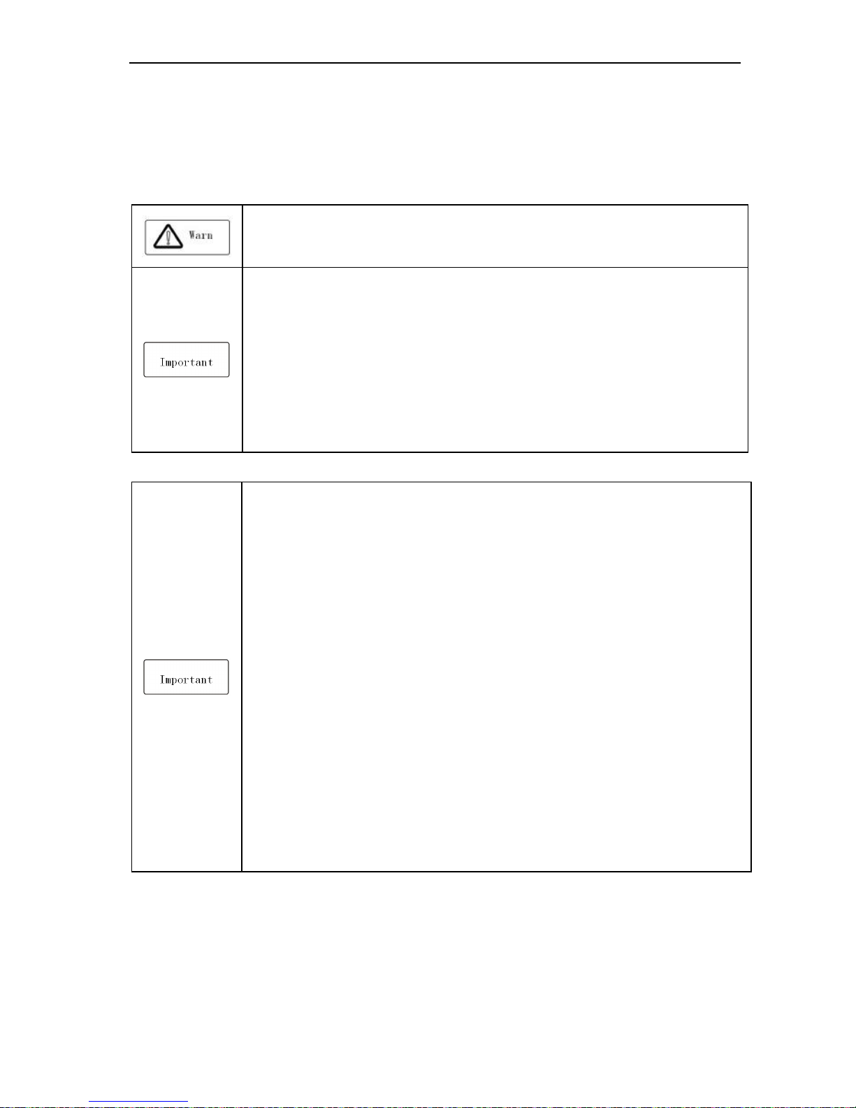
Warning signs and meanings
This manual has used below signs that mean there is an important part of security. While observing against the rules,
there is danger of injury even death or machine system damage.
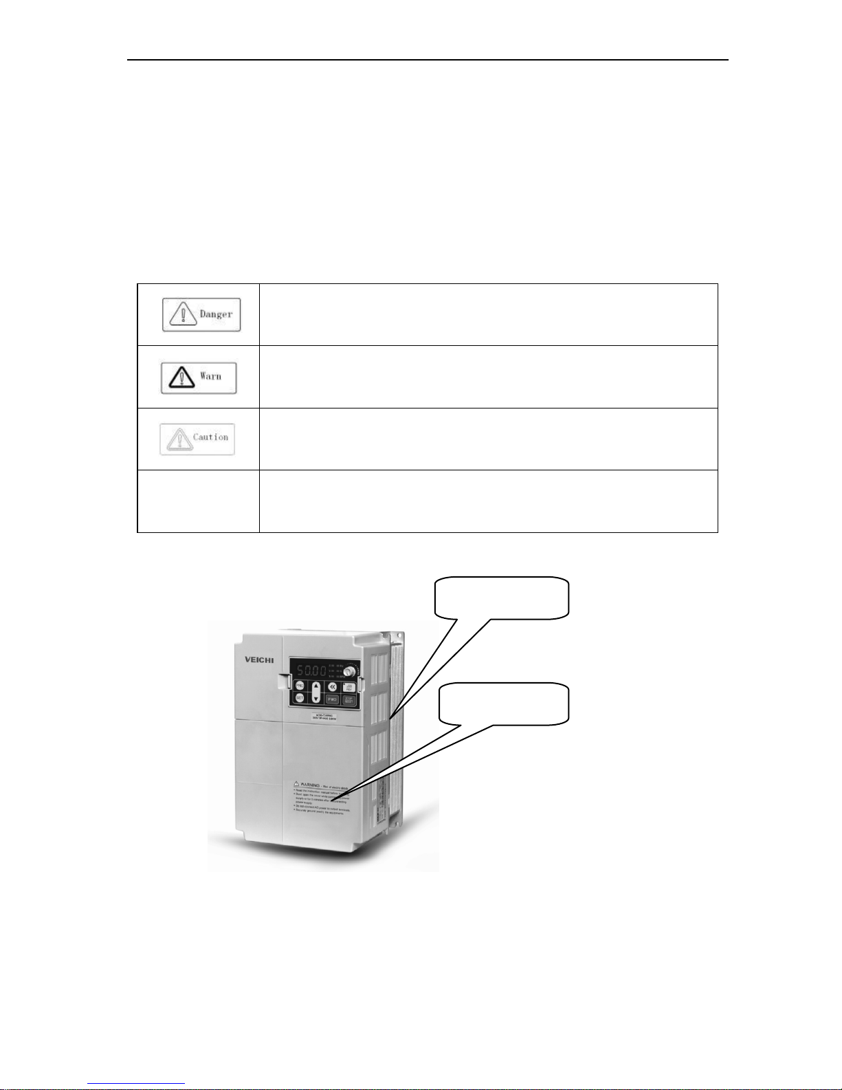
Danger: Wrong operation may cause death or large accident.
Warning: Wrong operation may cause death or large accident.
Caution: Wrong operation may cause minor wound.
Important: Wrong operation may cause the inverter and other machine system damage
Warning signs position
Drawing 1:Warning positions on crust of AC70 series inverter
Warning position 2
Warning position 1
AC70 VC CONTROL FREQUENCY INVERTER MANUAL OVERVIEW
2
Operation requirement
Only Professional trained person are allowed to operate the equipment such as installation, wiring, running, maintain
and etc. “Professional trained person”in this manual means the workers on this product must experience professional
skill train, must be familiar with installation, wiring, running and maintain and can rightly deal with emergency cases in
use.
Safety guidance
Safety regulations and warning signs come for your security. They are measures to prevent the operator and machine
system from damage. Please carefully read this manual before using and strictly observe the warning signs while
operating. Safety regulations and warning signs are classified into: routine regulation, transport and store regulation,
installation and wiring regulation, running regulation, maintenance regulation, dismantlement and disposal regulation.
● Routine regulation
● This product carries dangerous voltage and controls driver machine with potential danger. If
you don’t abide by the regulations or requirements in this manual, there is danger of body
injury even death and machine system damage.
● Only qualified personnel are allowed to operate the equipment.this product. Before using, the
operator must be familiar with all safety specifications and operation regulations in this
manual. Safe and stable work of the product is based on right operation and maintenance.
● Do not wire while the power is connected. Otherwise, there is danger of death for electric
shock. Before wiring, inspection, maintenance, please cut power supply of all related
equipments and ensure mains DC voltage in safe range. And please operate it after 5 mins.
● Away from children and public.
● Only used in application fields as maker stated. No use in equipments related to special fields
such as emergency, succor, ship, medical treatment, aviation, nuclear and etc.
● Unauthorized alteration or use of accessories which are not sold or recommended by the
maker may cause faults.
● Please make sure this manual is in the final user’ hand before using.
● Before installation and debugging please carefully read and totally understand these safety
regulation and warning signs.
● Transport and store regulation
●Correct transport, store, installation and careful operation an maintenance are important for
inverter safe operation.
● In transport and store process, make sure the inverter is free from impact and vibration. It
must be stored where is dry without corrosive air and conductive dust, and the temperature
must be lower than 60℃.
● Installation and wiring regulation
● Only professional trained person can operate it.
● Power wire, motor wire and control wire should be all connected firmly. Earth must be reliable
and earth resistance must be lower than 10Ω.
● Before opening the inverter, please disconnect all related equipment power supply and make
sure the mains DC voltage is in safe range and operate after 5mins.
● Human body electrostatic will damage inner sensitive components seriously. Before
operation, please follow ESD measures. Otherwise, there is danger of inverter damage.
● Inverter output voltage is pulse wave. If components such as capacitor which improves power
factor and pressure-sensitive resistance for anti-thunder and so on are installed at the output
side, please dismantle them or change to input side.
AC70 VC CONTROL FREQUENCY INVERTER MANUAL OVERVIEW
3
● No switch components such as breaker and contactor at the output side. (If there must be
one, please make sure the output current is 0 while the switch acting).
● The power supply cable and motor cable specifications must satisfy all conditions in table 3-7
3-8 .
● Run regulation
● Inverter runs at high voltage. So dangerous voltage is in some components inevitably.
● No matter where the fault is, there is danger of serious accident, even human body injury
what means dangerous malfunction possibility. So there must be additional external prevent
measures or other safety devices, such as independent current limiting switch, machinery
and so on.
● Maintenance regulation
● Only Shenzhen Veichi Electric co., ltd service department or its authorized service center or
professional person trained and authorized by Veichi can maintain the products. They should
be very familiar with the safety warning and operation gist in this manual.
● Any defective components must be changed in time.
● Before opening the inverter to repair please cut power supply of all related equipments and
ensure mains DC voltage in safe range. And please do operation after 5 mins.
● Dismantlement and disposal regulation
● Packing case can be reused. Please keep them and reuse or send back to maker.
● Dismantled metal components are retractable and can be reused.
●
Some components such as electrolytic capacitor are harmful to environment. Please dispose
according to environmental protection departments.
AC70 VC CONTROL FREQUENCY INVERTER MANUAL OVERVIEW
4
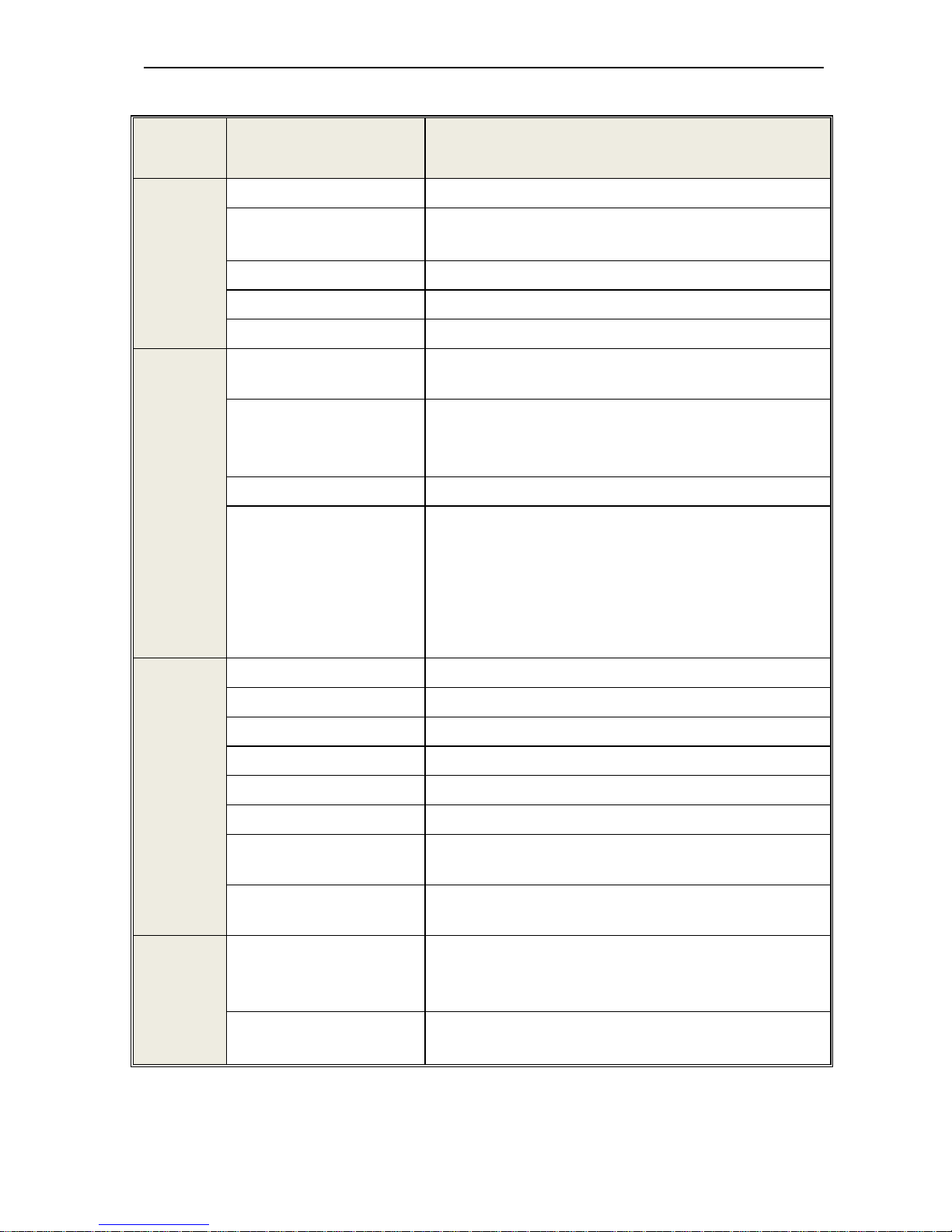
1.2 Technical Specification
Te ch .
Specification
Items Description
Power Input
Voltage, frequency single phase 220V, 3 phase, 220V,380V, 660V and 1140V
Allowable fluctuations
Voltage:<±15%; frequency±5%
Distortion of voltage to confirm to IEC61800-2
Closing striking current
less than rated current
Power Factor
≥0.94( integrated DC reactor)
Efficiency
≥96%
Power
Output
Output Voltage
3 Phase, 0~Input voltage, tolerance less than 5% in standard
rating condition
Frequency Control Range
G type: 0 to 400Hz, P type: 0-400Hz, Z type: 0-400Hz, L type:
0-400Hz,
H type: 0-3000Hz.
Output frequency accuracy
±5% of maximum frequency
Overload Tolerance
Z type: 150% rated current for 60 sec, 180% rated current for 30
sec, 250% rated current for instantaneous
G, H, L type model: 150% of rated output current for 60 sec,180% of
rated current for 10s, 2 00% of rated current for instantaneous
P type: 120% rated current 60 sec, 150% rated current for
instantaneous
Key Control
performance
Motor Control Mode Open loop sensorless vector control without PG, V/F control
Control system
Optimized Space Vector PWM Modulation
Carrier frequency
0.6~15kHz, Randomly-modulated carrier
Speed control range
OLV without PG with rated load: 1:100,
Stable speed control accuracy
OLV without PG: less than 1% rated synchronous speed
Torque response
OLV without PG control mode: ≤20ms
Frequency Accuracy
(Temperature Fluctuation)
Digital inputs: maximum × ±0.01%
Analog inputs: maximum × ± 0.2%
Frequency Setting Resolution
Digital inputs: 0.01 Hz
Analog inputs: 0.5% of maximum output frequency
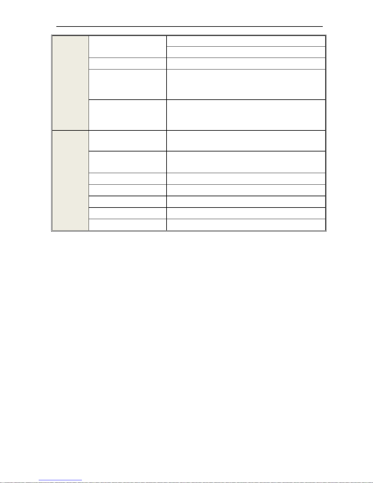
Standard
Function
DC Braking
Starting Frequency: 0.00 to 50.00Hz,
Braking Time: 0.0 to 60.0s
Braking current: 0.0 to 150% rated current
Torque boost
Auto torque boost:0.0% to 100%
Manual torque boost: 0.0% to 25%

AC70 VC CONTROL FREQUENCY INVERTER MANUAL OVERVIEW
5
V/F curve
5 kinds curve programmable setting:1 user setting, 1 of linear
characteristic torque curve setting. 3 kinds derating torque
setting( 1.5 power, 1.7 power, 2.0 Power curve )
Accel / Decel. curve
Two kinds curve: line Accel/Decel, S curve Accel/Decel.
4 Aceel/Decel time unit is 0.1s, maximum time 6500.0s
Rated output voltage
Power voltage compensation is available, setting range from 50 to
100%( rated voltage), the output voltage can't over than input
AVR( Auto Voltage Regulation
automatic voltage regulation for keeping output voltage stable when
fluctuation of grid
Auto energy saving running
Optimized the output voltage according the load to achieve energy
saving
Auto current limit
Auto current limit during running mode to avoid trip occurs
frequently
Momentary Power Loss with
no stop running function
To achieve continuous running with regenerative enery and DC bus
voltage regulation when momentary power loss
Standard Function
PID control, Carrier frequency adjustable, current limiter, Speed
Search, Momentary Power Loss restart,8 Step Speed (max), 3-wire
Sequence, Slip Compensation, Frequency Jump, Upper/lower
Limits for Frequency Reference, DC Injection Braking at Start and
Stop, Energy Saving Control, Modbus Comm RS485, Fault Restart,
job function, Cooling Fan on/off Switch, timing stop, high pulse
output, programmable auto running, swing frequency, counter,
frequency arriving detect and frequency lever detect.
Frequency Setting Methods
Keypad digital setting, potentiometer of keypad, analog voltage
terminal VS1, analog voltage terminal VS2, analog current terminal
AS, RS485 communication and multiple terminal, main and auxiliary
composition setting.
Feedback Input Channel
voltage terminal VS1, VS2, current terminal AS, communication ,
and pulse input PUL
Running command channel keypad given, external terminal given, communication given
Input command signal
Start, Stop, FEW/Reverse, Job, Multiple speed, free stop, Reset,
Accel/Decel time, Frequency set point channel, External fault
Output signal
2 Photo coupler relays: 2 (24 V, up to 50 mA)
1 Contact relays: 1 (250 Vac/up to 1 A, 30 Vdc/up to 1 A)
0-10V output, 4 to 20mA output
Frequency pulse output
Protection function
Overvoltage, under voltage, current limit, over current, overload,
electric thermal relay, overheat, Stall prevention, parameter lock
AC70 VC CONTROL FREQUENCY INVERTER MANUAL OVERVIEW
6
keypad
Display
LED Display
One line digit-segments LED display to monitor 1 running status
Double line digit-segment display to monitor 1 running status
Parameters copy upload and download parameter code to achieve easy copy
Monitor Function
Output frequency, Frequency set point, Out current, Output voltage,
motor speed, PID feedback value, PID given setting, IGBT module
temperature, I/O terminal status.
Alarms
Overvoltage, under voltage, over current, short circuit, phase loss,
over load, over heat, stall prevention, current limit, parameter lock
damage, running status at present alarm, past trip alarm
Environment
Installation Site
Indoor, Altitude should less than 1000m, Free corrosive gases and
direct sunlight
Running Temperature,
humidity
-10~+40°C ( wall mounting),
20% to 95% RH (No condensation)
Vibration Less than 0.5g when frequency less than 20Hz
Storage Temperature -25—+65°C
Installation mode Wall-mounted mode, floor stand cabinet install
Protection Degree IP20
Cooling Method Forced air-cooling
Table 1: Technical Specification
AC70 VC CONTROL FREQUENCY INVERTER MANUAL BEFORE USE
7
Chapter 2 Before Use
2.1 Purchase Inspection
Pls check whether any package is damaged while receiving the product you ordered. If the package is ok, pls open it
and check the inverter. If damage caused in transport, it is not duty of Veichi company. But please contact Veichi or the
transport company immediately.
After checking the product, please also check if the model is the one you ordered.The model of the product is on the
nameplate “MODEL”column. If the model is not in accordance with your need, please contact the agent or the sales
departments in our company.
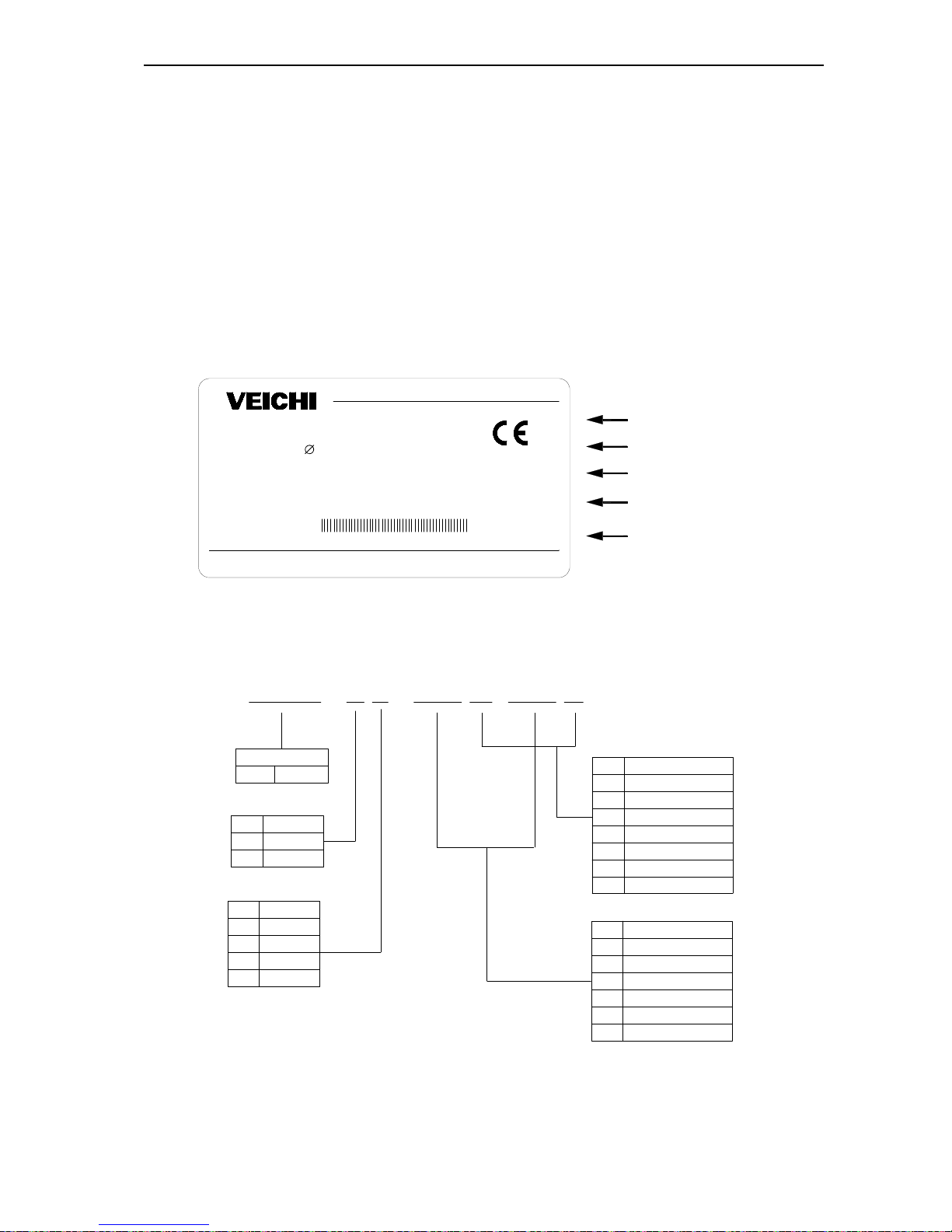
2.2 Nameplate
Nameplate position and content
MODEL: AC70-T3-011G/015P
SOURCE: 3
380V 50/60Hz
OUTPUT1
: 11KW 25A 0.00-400.0Hz
SER NO:
OUTPUT2
: 15KW 32A 0.00-400.0Hz
G models output
Model
P models output
Input power
Production series no
******************
Chart 2-1: AC70 series inverter nameplate
Model explanation
AC70 - T 3 - 011 G /015 P
2 220V
3 380V
6 660V
G
P
Z
7R5
011
015
7.5
11
15
018
022
030
18.5
22
30
L
11
1140V
H
AC70
GD
PD
Cabinet with base
Cabinet with base
code
voltage class
T
three phase
S
single phase
code
voltage class
code
inverter type
general format
blower and water pump
plastic machine
draw bench
mid inverter governor
code
fit power of motor(kW)
General use
inverter series
Chart 2-2: AC70series inverter nameplate meaning and naming rules

AC70 VC CONTROL FREQUENCY INVERTER MANUAL BEFORE USE
8
2.3 Rated Output Current
Input voltage 220V 380V 660V 1140V
Rated power (kw) Rated output current (A)
0.4 2.5
0.75 4 2.3
1.5 7 3.7
2.2 10 5.0
4 16 10
5.5 20 13
7.5 30 17 10
11 42 25 15
15 55 32 18
18.5 70 38 22
22 80 45 28
30 110 60 35
37 130 75 45 25
45 160 90 52 31
55 200 110 63 38
75 260 150 86 52
90 320 180 98 58
110 380 210 121 75
132 420 250 150 86
160 550 310 175 105
185 600 340 198 115
200 660 380 218 132
220 720 415 235 144
250 470 270 162
280 510 330 175
315 600 345 208
355 670 380 220
400 750 430 260
450 810 466 270
500
860 540 325
560 990 600 365
630 1100 680 400
AC70 VC CONTROL FREQUENCY INVERTER MANUAL INSTALLATION AND WIRING
9
Chapter 3: Installation and Wiring
3.1 Safety Precautions
This chapter explains the warnings for safe use and stable running of the product.
Cautions in use
●While install the inverter in the closed cabinet, please build in cooling fan, air-conditioner or
other cooling equipment to ensure the temperature at the air-in port below 40℃. So that the
inverter can work safely and reliably.
●While installing, please use cloth or paper cover the inverter to prevent metal dust, oil, water
and others.And remove it carefully after working.
● While operation, please follow the ESD regulations. Otherwise, the inverter may be
damaged.
● While multi inverters are installed in the same cabinet, enough space must be left for cooling
fan.
●Inverter can not work over rated range.Otherwise, the inverter may be damaged.
●While transporting the inverter, please hold the firm case. If only hold the pre-cover, there is
danger of inverter main body falling, injury or inverter damage.
Cautions in use motor
●Different motor has different max allowable running speed. Motor can not run over the max
allowable running speed.
●While inverter is running at low speed, the motor auto-cool effect is seriously worse. If motor
runs at low speed for long time, it will be damaged for overheat. If needed, please use special
motor for inverter.
●While constant speed machinery runs at inconstant speed, there maybe sympathetic vibration.
Please install vibration-proof rubber under motor rack or use jumping frequency control
function.
●While using frequency inverter or working frequency power supply to drive, the torque
characteristic are different. Please do confirm the torque characteristic of the equipment
connected.
●The rated current of shift gear motor is different from that of standard motor. Please confirm it
and choose the right frequency inverter. Moreover, please do switch the pole while the inverter
input current is 0. Otherwise it may bring inverter protection or damage.
●The rated current of diving motor is higher than that of standard motor, please confirm it and
choose the right inverter.
●While the wire between motor and inverter is long, the max torque of the motor will reduce for
voltage drop. So please use thick cable while the distance between the motor and the inverter
is long.
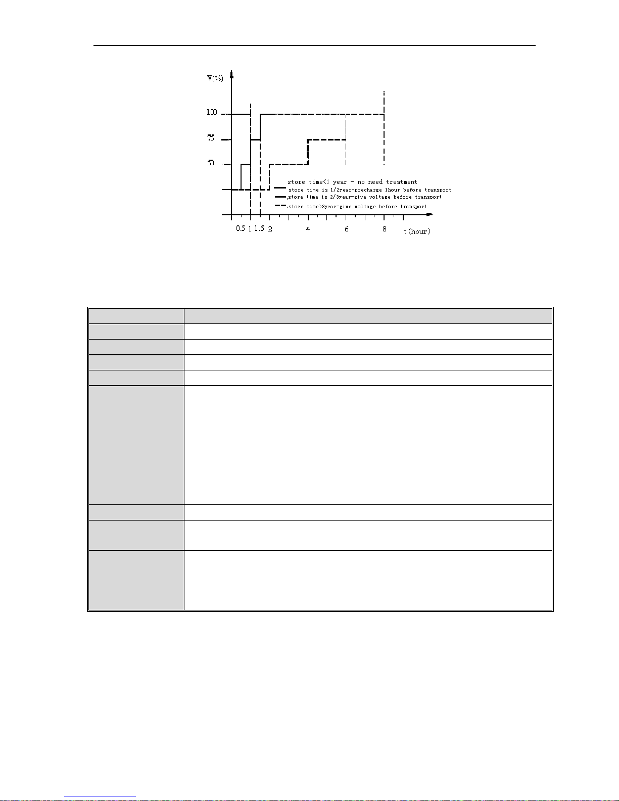
3.2 Treatment for Inverter after Longtime Store
If the inverter store time is over one year, you must pre-charge the aluminum capacitor in the inverter again and install
the inverter after the aluminum capacitor characteristic recovering. For the specific method, please follow the grads in
the chart below and give corresponding proportional voltage for every grad more than 30 mins while the inverter is
no-load.
If the input voltage of one grad is at the action critical point of contactor, fan or other equipment, please increase or
reduce the corresponding input voltage for the grad to avoid any component working under critical state.
AC70 VC CONTROL FREQUENCY INVERTER MANUAL INSTALLATION AND WIRING
10
Chart 3-1: treatment for inverter after longtime store
3.3 Inverter Stable Running Environment
Installation environment is very important to the best use of this product for long time. Pls install this product in the
environment as the following table requirement.
Environment Requirement
Install place Indoor without direct sunshine
Install temperature -10 ~ +40℃
Store temperature -20 ~ +60℃
Humidity <95%RH, no condensation
Surrounding
Please install the inverter in place as follows:
● Place without oil mist, corrosive gases, flammable gas, dust or etc.
● Place without metal dust, oil, water or etc into inverter (please do not install inverter on
flammable material such as food and etc).
● Place without radioactive material or flammable material.
● Place without poisonous gases or liquid.
● Place with very little salification erosion.
● Place whihout direct sunshine.
Altitude <1000m
Vibration
<10~20Hz:9.8m/s2
<20~55Hz:5.9m/s2
Installation and
cooling
● Inverter can not be installed horizontally must be installed vertically.
● Please independently install high heating equipments such as braking resistor and etc which
can not be installed in the same cabinet with inverter, installed at the air-in port of the inverter
is strictly prohibited.
Table 3-1:AC70 series inverter running environment condition
● In order to improve the product stability, pls do not use the inverter where temperature changes sharply. While
using in closed space such as control cabinet, please use cooling fan or air-condition to cool inverter to avoid
temperature over limit range. Please also prevent inverter from freeze, too low temperature may cause components
freeze fault.
AC70 VC CONTROL FREQUENCY INVERTER MANUAL INSTALLATION AND WIRING
11
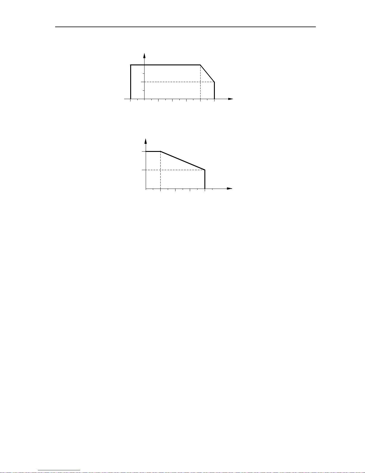
● Derate according to the chart while over temperature limit.
30
25
100
75
50
4020100-10 50
TEMPERATURE(℃)
PERMIT OUTPUT CURRENT(%)
Chart 3-2:AC70 series inverter derating surve while over permit temperature
● Derate according to the chart while over altitude limit.
0 1000 2000 4000
80
100
3000 ALTITUDE(M)
PERMIT OUTPUT CURRENT(%)
Chart 3-3:AC70 series inverter derating surve while over permit altitude
3.4 EMI Protection
The inverter is designed to be used in industrial environment with strong electromagnetic interference. Generally
speaking, if the installation quality is good, it is ensured that the inverter can work safely without fault. Please install the
inverter according to the following rules to ensure stable running and avoid electromagnetic interference impact.
● Ensure that all equipments in the cabinet have been connected reliably to the common Y-type earth point or earth
bus with thick and short cable. The motor earth should be as close as possible. Please do not connect the motor
case to the inverter earth terminal or the protective area of control system.
● Ensure that all equipments connected to the inverter have been reliably connected to the same earth net or Y-type
earth point with thick and short cable.
● The conductor has better to be flat and with multi core, what has lower resistance at high frequency.
●The cutting terminal should be as soigne as possible. Unshielded wire section must be as short as possible.
● In control cable wiring, it should be as far from the power supply cable and motor cable as possible. And
independent cable trough should be used. While the control cable must cross to the power supply cable or motor
cable, it should be 90º vertical cross.
● Ensure that the contactor in the cabinet has wave surge suppresser. Or‘R-C’damping circuit is connected to the
winding of AC contactor. Voltage dependent resistor corresponding to the winding voltage is used. And freewheel
diode or components such as voltage dependent resistor corresponding to the winding voltage are connected to DC
contactor. It is very important while contactor, controlled by output relay of inverter, acts frequently.
● Cable connected to motor should be shielded cable or armoured cable. The two barriers are earthed reliably by
cable grounding card.
● Build noise filters at the input side to reduce electromagnetic interference from other equipments at the power grid
side. The noise filter should be as close to the inverter power input terminal as possible. Meantime, the filter must
earth reliably as the inverter.
● Build noise filters at the output side to reduce radio interference and inductive disturbance. The noise filter must be
as close to the inverter output terminal as possible. Meantime, the filter must earth reliably as the inverter.
AC70 VC CONTROL FREQUENCY INVERTER MANUAL INSTALLATION AND WIRING
12
● Anytime, control circuit wire should be shielded cable.
● Add zero phase reactor in power supply wire near inverter input terminal and add zero phase reactor in the motor
wire near inverter output terminal to reduce electromagnetic interference to the inverter efficiently.
● Earthing Right and reliable earthing is the basic condition of safe and reliable running of the product. For right
earthing, please read the following notice carefully.
●In order to avoid electric shock, earthing cable should be the size as electric
equipment technique standard required and cable length should be as short as
possible. Otherwise, inverter leakage current will cause unstable potential of the
earthing terminal which is far from the earthing point, and electric shock accident will
happen frequently.
●Earth terminal must be earthing. Earth resistance must be below 10Ω. Otherwise,
there is danger of death.
● Please do not share earth cable with welder or other big current/pulse power
equipment. Otherwise, inverter will act abnormally.
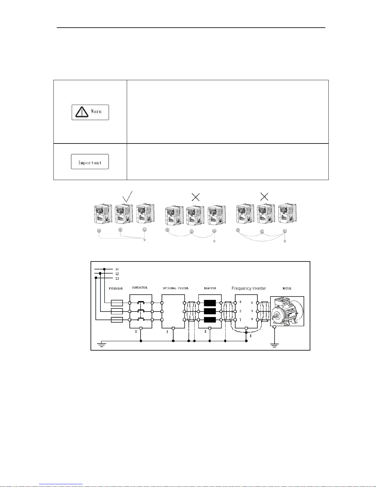
●While multi inverters are used at the same time, please do not wind the earth wire to
loop-type. Otherwise, inverter will act abnormally.
Chart 3-4: multi AC70 series inverters united earthing
Chart 3-5:AC70 series inverter system earthing
Remark: motor must earth as close as possible. Motor case can not be connected to the inner earth terminal of the
inverter. It also can not share the earth net with the control system.
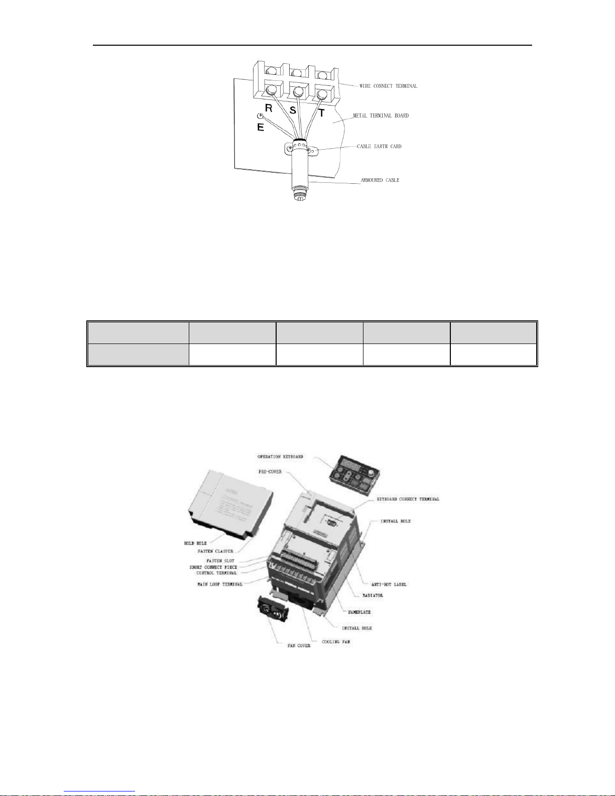
● Shield of inverter power cable, motor cable, control cable Cable
Shielding layer (reticulate/armoured) should be winded reliably by cable earth card and fix to inverter earth piece by bolt.
Please refer to the following chart.
AC70 VC CONTROL FREQUENCY INVERTER MANUAL INSTALLATION AND WIRING
13
Chart 3-6:Cable earth card for cables earthing
●Corresponding relationship between inverter/motor cable length and carrier frequency.
While cable distance between inverter and motor is long (especially low frequency output), cable voltage drop will make
motor torque reduce. Further more, cable HF leakage current will increase. Then inverter output current will increase,
that will cause inverter over-current trip. The current detection accuracy and running stability will be impacted. Please
follow as below table to adjust carrier frequency according to the cable length. While the cable distance is over 100m,
please adopt distributed capacity reduce measure (Such as “no metal conductor covers cable”, “wire each phase cable
apart” and so on).
Cable length <20m 20~50m 50~100m >100m
Carrier frequency 0.7~15kHz 0.7~8kHz 0.7~4kHz 0.7~2kHz
Table 3-2: Corresponding relationship between inverter/motor cable length and carrier frequency
3.5 Machinery Installation
Installation notice and related requirement
● AC70 inverter components
Chart 3-7:AC70 series inverter components
AC70 VC CONTROL FREQUENCY INVERTER MANUAL INSTALLATION AND WIRING
14
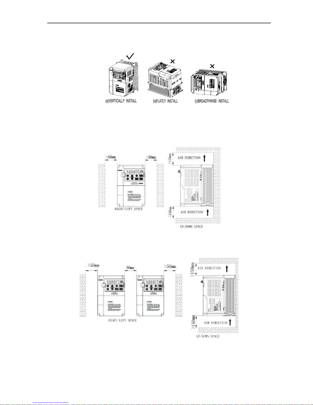
● Installation direction
To prevent inverter cooling effect reducing, please do install the inverter vertically.
Chart 3-8:AC70 series inverter installation direction
● Installation space
Single machine installation: to ensure enough ventilation and wiring space for inverter cooling, please follow installation
conditions as follows. The back of the inverter should stick to the wall. So that the surrounding air of radiator can flow
freely to ensure the cooling effect.
Chart 3-9:Single AC70 series inverter installation space
Multi inverters paratactic installation: while installing multi inverters in cabinet, please ensure installation space as
follows.
Chart 3-10: Multi AC70 series inverters paratactic installation space requirement
AC70 VC CONTROL FREQUENCY INVERTER MANUAL INSTALLATION AND WIRING
15
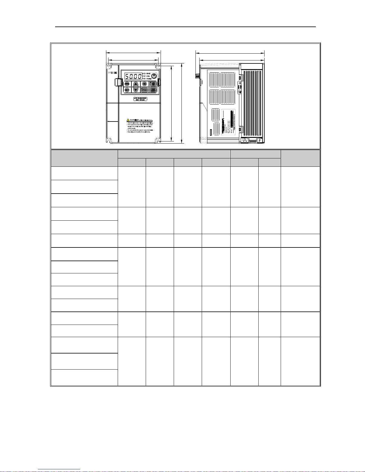
Dimension of Inverter and Keyboard
W
W1
D
D1
H
H1
Inverter model
Inverter size Install size
Install
aperture
W H D D1 W1 H1
AC70-S2-R40G
122 182 154.5 145 112 171 ф5 AC70-S2-R75G
AC70-S2-1R5G
AC70-S2-2R2G
159 246 157.5 148 147.2 236 ф5.5
AC70-S2-004G
AC70-S2-5R5G 195 291 167.5 158 179 275 ф7
AC70-T3-R75G/1R5P
122 182 154.5 145 112 171 ф5
AC70-T3-1R5G/2R2P
AC70-T3-2R2G/004P
AC70-T3-004G/5R5P
159 246 157.5 148 147.2 236 ф5.5
AC70-T3-5R5G/7R5P
AC70-T3-7R5G/011P
195 291 167.5 158 179 275 ф7
AC70-T3-011G/015P
AC70-T3-015G/018P
(plastic cover machine)
230 330 200 190 208 315 Ф7
AC70-T3-018G/022P
(plastic cover machine)
AC70-T3-022G/030P
(plastic cover machine)
AC70 VC CONTROL FREQUENCY INVERTER MANUAL INSTALLATION AND WIRING
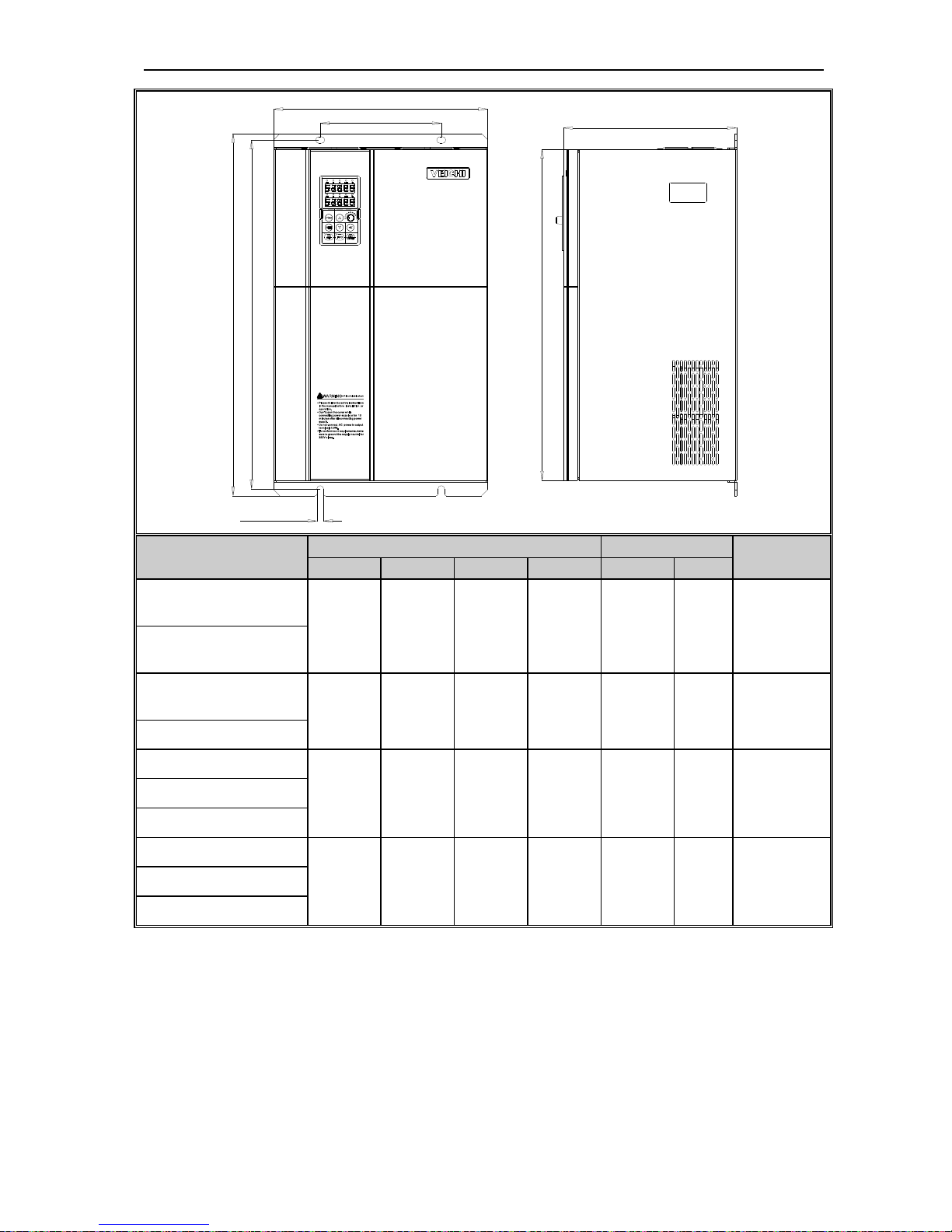
16
W
W1 D
H
H1
H2
Install aperture
Inverter model
Inverter size Install size
Install
aperture
W H D H2 W1 H1
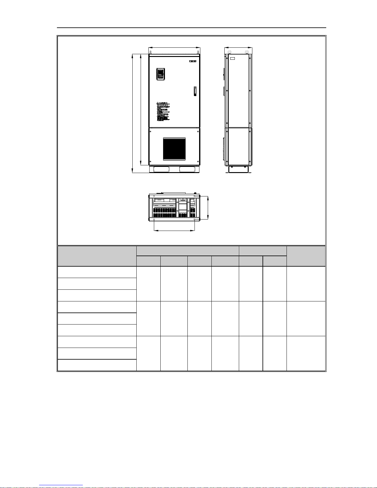
AC70-T3-015G/018P
(steel cover machine)
235 345 200 311 160 331.5
ф7
AC70-T3-018G/022P
(steel cover machine)
AC70-T3-022G/030P
(steel cover machine)
255 410 225 370 180 395 Ф7
AC70-T3-030G/037P
AC70-T3-037G/045P
305 570 260 522 180 550 Ф9 AC70-T3-045G/055P
AC70-T3-055G/075P
AC70-T3-075G/093P
380 620 290 564 240 595 ф11 AC70-T3-093G/110P
AC70-T3-110G/132P
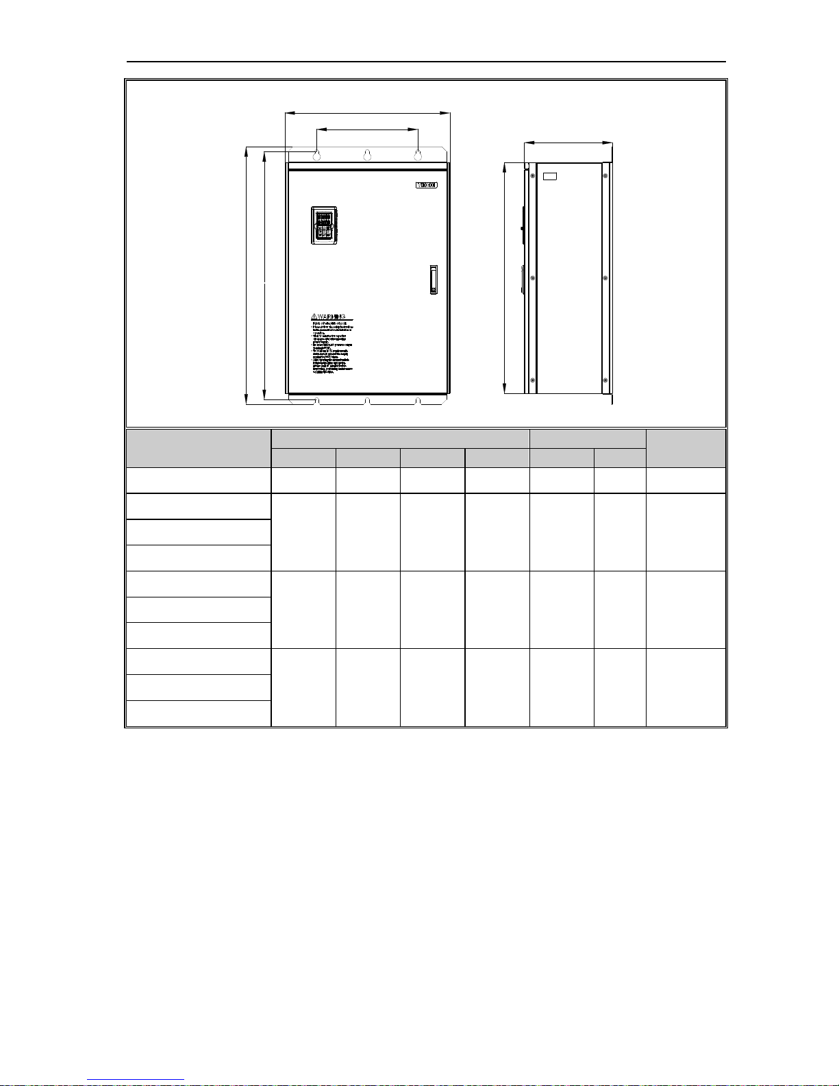
AC70 VC CONTROL FREQUENCY INVERTER MANUAL INSTALLATION AND WIRING
17
H1
H
H2
D
W1
W
Inverter model
Inverter size Install size
Install
aperture
W H D H2 W1 H1
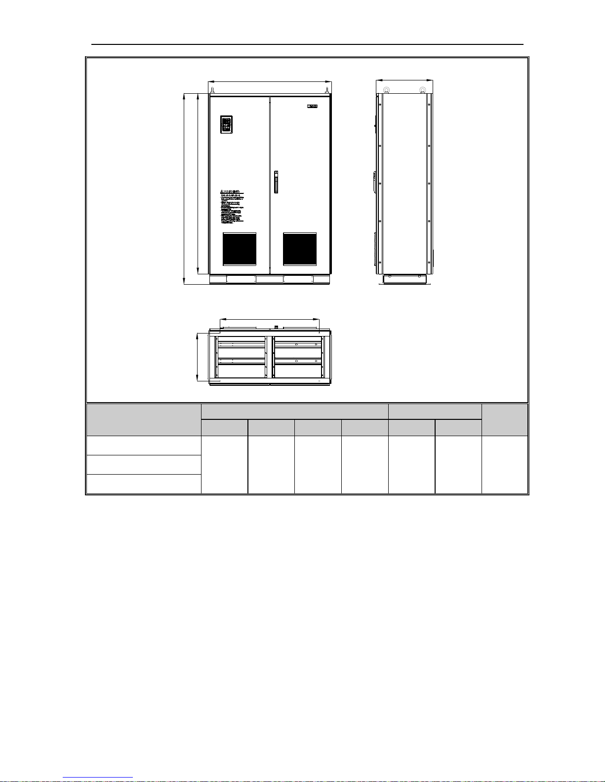
AC70-T3-132G/160P 500 780 340 708 350 755 ф11
AC70-T3-160G/185P
650 1060 400 950 400 1023 ф16 AC70-T3-185G/200P
AC70-T3-200G/220P
AC70-T3-220G/250P
750 1170 400 1050 460 1128 ф18 AC70-T3-250G/280P
AC70-T3-280G/315P
AC70-T3-315G/355P
850 1280 450 1150 550 1236 ф20 AC70-T3-355G/400P
AC70-T3-400G/450P
NOTE: Without build-in dc reactor
AC70 VC CONTROL FREQUENCY INVERTER MANUAL INSTALLATION AND WIRING
18
D1
W1
D
W
H
H1
Inverter model
Inverter size Install size
Install
aperture
W H D H1 W1 D1
AC70-T3-160GD/185PD
650 1600 400 1500 492 332 ф14 AC70-T3-185GD/200PD
AC70-T3-200GD/220PD
AC70-T3-220GD/250PD
750 1700 400 1600 582 332 ф14 AC70-T3-250GD/280PD
AC70-T3-280GD/315PD
AC70-T3-315GD/355PD
850 1800 450 1700 622 382 ф14 AC70-T3-355GD/400PD
AC70-T3-400GD/450PD
NOTE: With build-in dc reactor
AC70 VC CONTROL FREQUENCY INVERTER MANUAL INSTALLATION AND WIRING
19
H
H1
D1
W1
D
W
Inverter model
Inverter size Install size
Install
aperture
W H D H1 W1 D1
AC70-T3-450G/500P
1200 1850 550 1750 960 466 ф14 AC70-T3-500G/560P
AC70-T3-560G/630P
Table 3-3:AC70 series inverter dimension
AC70 VC CONTROL FREQUENCY INVERTER MANUAL INSTALLATION AND WIRING
20
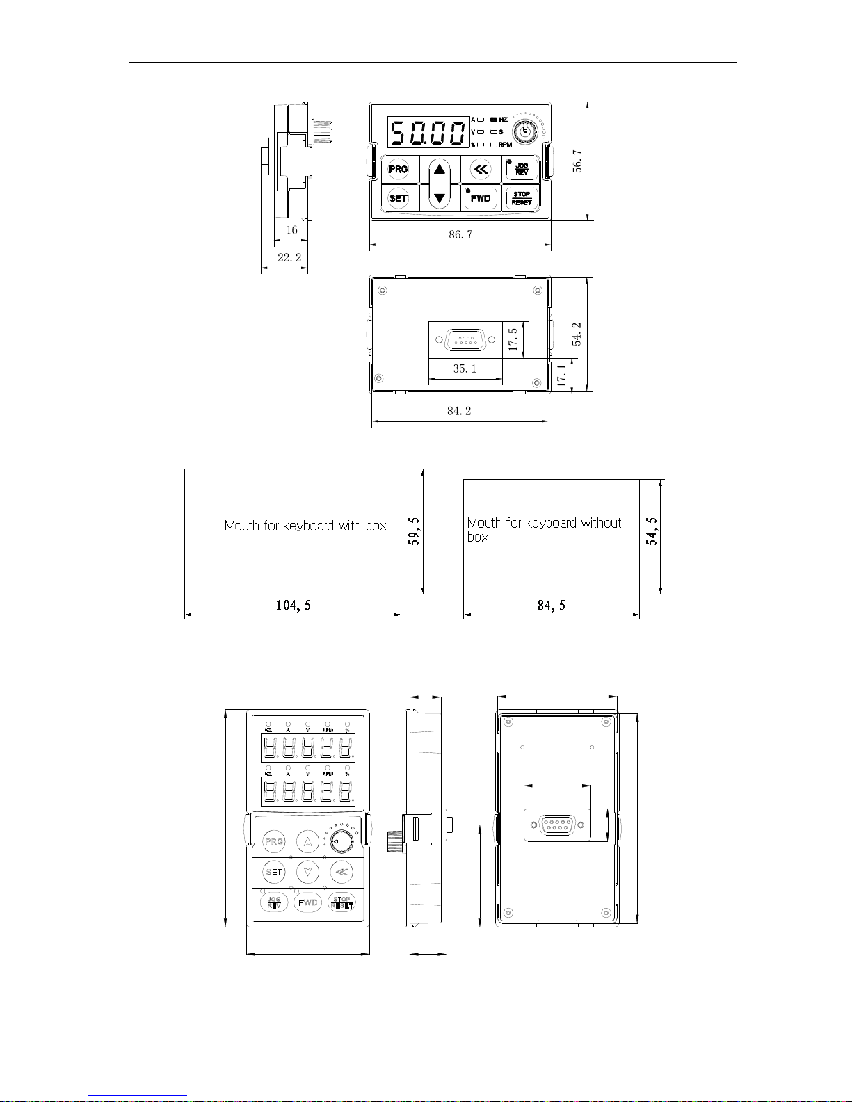
Keyboard dimension
Chart 3-11:AC70 series inverter 1 line LED keyboard dimension
Chart 3-12:AC70 series inverter mouth for 1 line LED keyboard dimension
114.5
65.5
19.5
16.5
17.1
110.5
63.5
35.6
53.75
Chart 3-13:AC70 series inverter 2 line LED keyboard dimension
AC70 VC CONTROL FREQUENCY INVERTER MANUAL INSTALLATION AND WIRING
21
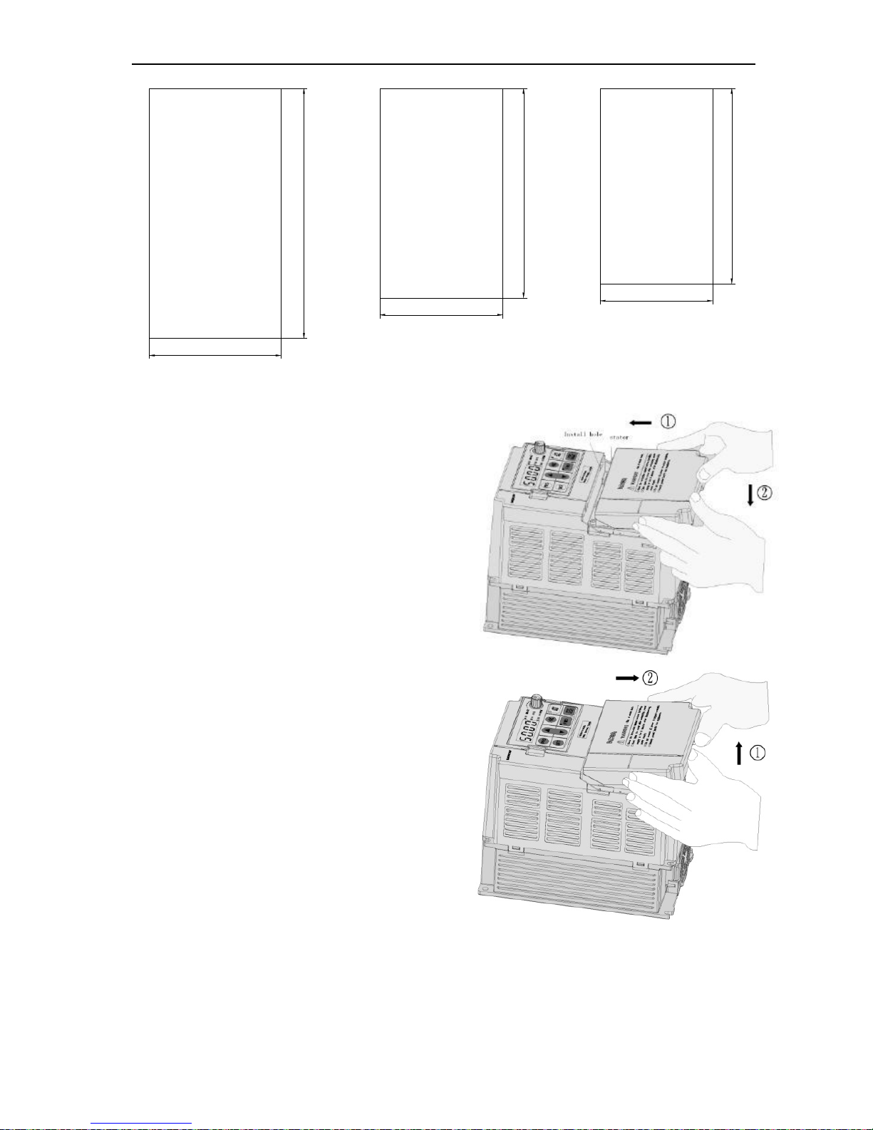
119
70
111
64
142
75
Mouth for keyboard with box
AC70-T3-160G/630P
Mouth for keyboard with box
AC70-T3-015G/132P
Mouth for keyboard with box
Chart 3-14:AC70 series inverter mouth for 2 line LED keyboard dimension
Note: LCD keyboard total same size as LED keyboard.
Dismantle and install tail-hood
Installation: First the tail-hood upwardly inclines around 15
degrees and inserts the top fixed flat into the fixed hole in the
front cover. Then slightly press the tail-hood downward. While
your hear "Ka", it means that the tail-hood is into the place.
Chart 3-15:AC70 series inverter tail-hood installation
Dismantlement: At the tail of the frequency inverter, there is a
special dismantlement hole design. Put your finger into the
hole, upwardly pull the cover with a little force until the buckle
between the tail-hood and the crust tear off, and then remove
the tail-hood down.
Chart 3-16:AC70 series inverter tail-hood dismantlement
AC70 VC CONTROL FREQUENCY INVERTER MANUAL INSTALLATION AND WIRING
22
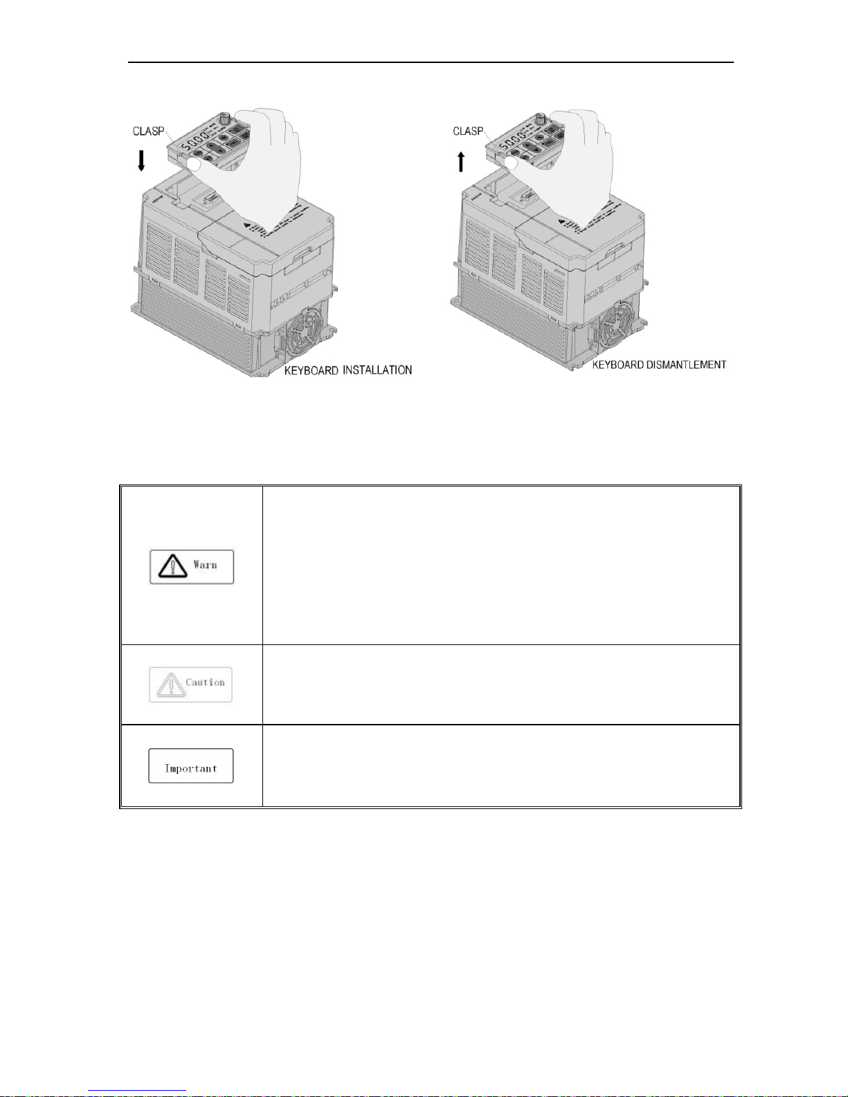
Dismantlement and installation of keyboard
Chart 3-17:AC70 series inverter keyboard installation and dismantlement
3.6 Electric Installation
This chapter explains the regulations that users have to obey to ensure safe use, best performance and reliable
running.
Safety precaution
● Must earth reliably while inverter is running. Otherwise there is danger of casualty and
unstable inverter performance.
● To ensure safe running, only trained professional person can do installation and wiring
job.
● No operation under power connected state. Otherwise there is danger of electric shock
even death.
● Before operation, please cut all related equipments power, ensure that the main circuit
DC current has dropped to safe range. And please operate after 5 mins.
● Control cable, power cable and motor cable must be separated. They can not be in the
same cable trough or cable rack.
● This equipment can only be used as the maker states. Please consult Veichi while using
in special case.
● No insulation test for the inverter or the related cable by HV insulation test equipment.
● If the inverter or the peripheral equipment (filer, reactor and etc) needs insulation test,
firstly 500V megohmmeter should be used to test the insulation resistance which should
not be lower than 4MΩ.
AC70 VC CONTROL FREQUENCY INVERTER MANUAL INSTALLATION AND WIRING
23
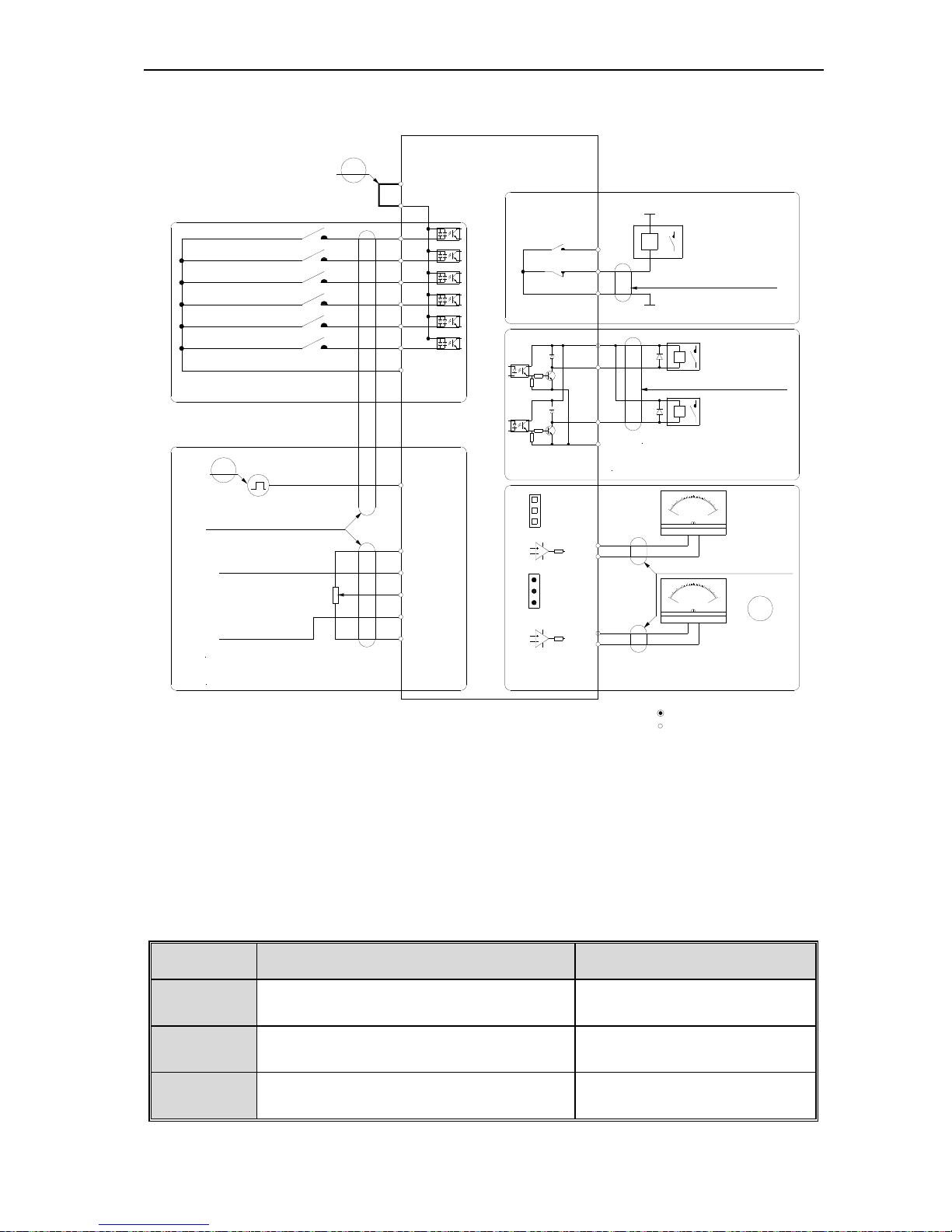
Standard diagram
● Standard diagram
Note1
Note:multiple function digtal input default
setting
TA
TB
TC
+24V
Y1
_
mA
2
0
10
0
-
+
0
5
1
0
V
_
+
-
GND
A01
VR
VR mini
2Kohm
Analog curr ent Input
+10V
Frequency reference setting input
VS2
GND
AS
VS1
twisted-pair shielding line
(grounding nearby)
pulse input
PUL
Multi-function digital input
COM
X3
X4
X6
X5
X1
X2
PLC
+24V
Frequency Inverter
GND
A02
coil
Y2
COM
passive source output
AC220V
AC0V
J1
J2
J3
switch
Maximum output:
3A/240VAC
5A/30VDC
2. VS1/VS2 terminal resistor valuve 89ohm
1 Maximum output 50mA +10V input terminalNote
:
2 Maximum output of Y1/Y2 DC24V/50mA
Note
:
Mark:
1. stand for main loop terminal
(Forward Run/Stop)
(0~5V)/(0~10V)
(0~20mA)/(4~20mA)
3AS terminal resistor valuve 250ohm
J4
J5
(Reverse Run/Stop)
(Jog run forward)
(Jog run Reverse)
(Free stop)
(Fault reset)
Note3
Analog voltage Input
twisted-pair shielding line
(grounding nearby by inverter)
twisted-pair shielding
line (grounding nearby by inverter)
Note: 1
Maximum output of +24V
terminal-DC 24v/100mA
Pin
switch
coil
coil
twisted-pair shielding
line (grounding nearby by inverter)
Note2
Note: Maximum output is 2mA when
A01/A02 as for frequency voltage signal
output
2. stand for control loop terminal
collector type status output
analog monitor signal output
Chart 3-18:AC70 series inverter standard diagram
Note: 1.NPN or PNP transistor signal can be selected as input of multi-function input terminal(X1~X6). Inverter
built-in power supply (+24V terminal) or external power supply (PLC terminal) can be chosen as bias
voltage. Factory setting ‘+24V’ short connect with ‘PLC’.
2. Analog monitor output is special output of meters such as frequency meter, current meter, voltage meter
and etc. It can not be used for control operations such as feedback control.
3. As there are multi pulse styles, please refer to the line connect mode description details.
● Auxiliary terminal output capacity
Terminal Function definition Max output
+10V
10V auxiliary power supply output, constitutes loop
with GND.
50mA
A01/A02 Analog monitor output, constitutes loop with GND.
As frequency,voltage signal, max
output 2mA
+24V
24V auxiliary power supply output, constitutes loop
with COM.
100mA
AC70 VC CONTROL FREQUENCY INVERTER MANUAL INSTALLATION AND WIRING
24
Y1/Y2
Collector open circuit output, can set the
action-object by program.
DC24V/50mA
TA/ TB/TC
Passive connector output,can set the action-object
by program.
3A/240VAC
5A/30VDC
Table 3-4:AC70 series inverter auxiliary terminals output capacity
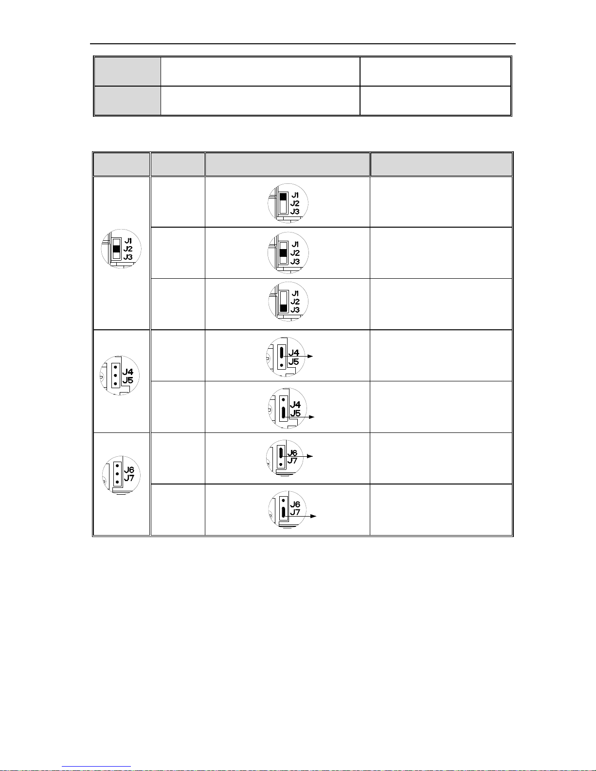
● Switch terminals connection function specification
Switch
terminal
Optional
position
Picture example Function specification
(K2)
J1
(AO2)
0.0~50kHz open collect pole pulse
frequency output
J2
(AO2)
0~20mA current output or
4~20mA current output
J3
(AO2)
0~10V voltage output
(K1)
J4
J4 connect
(AO1)
0~10V voltage output
J5
J5 conne
(AO1)
0~20mA current output or
4~20mA current output
(K3)
J6
J6 conne
RS485 communication initial port
connect matching resistor 120Ω
J7
J7 conne
Matching resistor disconnect
Table 3-5:AC70 series inverter switch terminal connection function specification
AC70 VC CONTROL FREQUENCY INVERTER MANUAL INSTALLATION AND WIRING
25
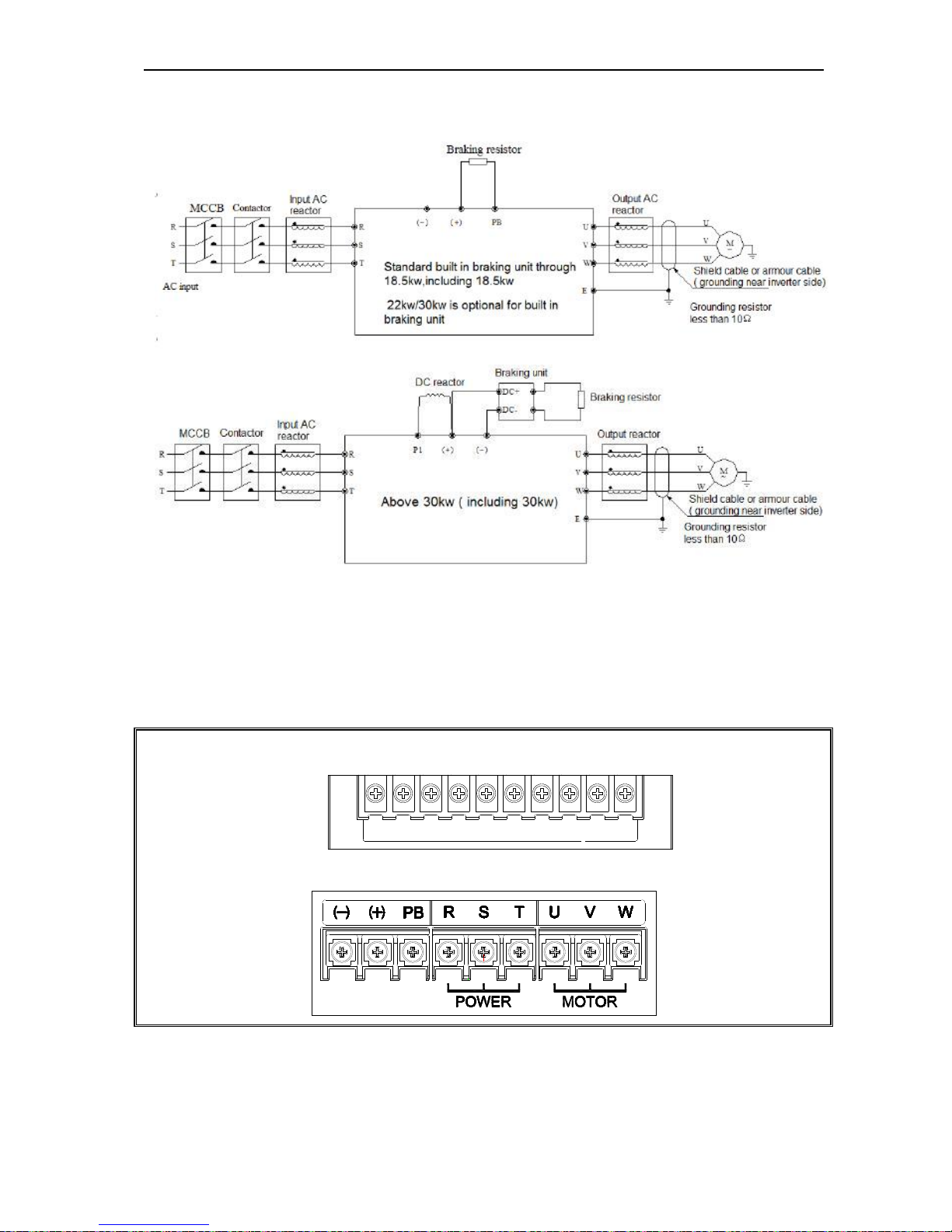
Main circuit wiring
● Main circuit wiring
Chart 3-19:AC70 frequency inverter main circuit wiring
Note: 1, Fuse, dc reactor, braking unit, braking resistor, input actor, input filter,output reactor, output filter are optional
parts, please refer to “peripheral equipment”.
2, P1 terminal and (+) short connect. If need add dc reactor, please take away the short connect part between P1 and
(+).
Main circuit terminals
● Main circuit terminals array and definition
Arrangement sequence of main circuit terminal with 18.5kW or less power(15 ~ 18.5KW for steel cover machine)
(-)
TSR
PB
UWV
(+)
E
Arrangement sequence of main circuit terminal with 15-22KW(15~22KW for plastic cover machine)
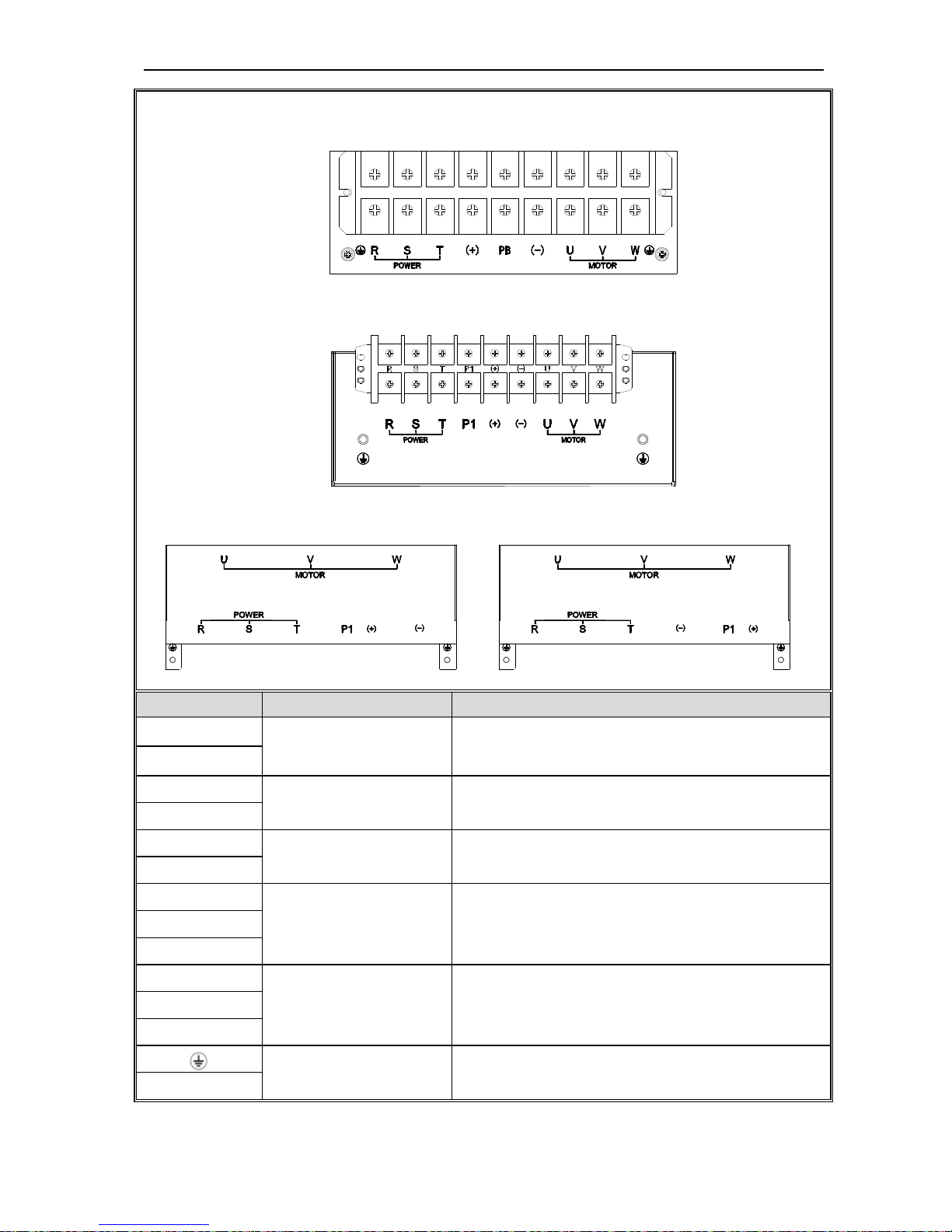
AC70 VC CONTROL FREQUENCY INVERTER MANUAL INSTALLATION AND WIRING
26
Arrangement sequence of main circuit terminal with 22~30KW (standard machine without PB terminal)(22KW for steel
cover machine)
Arrangement sequence of main circuit terminal with 37~110kW
Arrangement sequence of main circuit terminal with 132kW: Arrangement sequence of main circuit terminal with 160~560kW
Terminal Name
(-)
DC power terminal
DC power output, (-) means DC bus cathode, (+) means DC
bus anode, used for external braking unit.
(+)
(+)
Braking resistance terminal Used for external braking resistance to realize quick stop.
PB
P1
DC reactor terminal Used for external DC reactor.
(+)
R
Inverter input terminal Used to connect 3-phase AC power supply. S
T
U
Inverter output terminal Used to connect the motor. V
W
Earth Earth terminal, earth resistance<10 OHM
E
Table 3-6:AC70 series inverter main circuit terminals array and definition
AC70 VC CONTROL FREQUENCY INVERTER MANUAL INSTALLATION AND WIRING
27
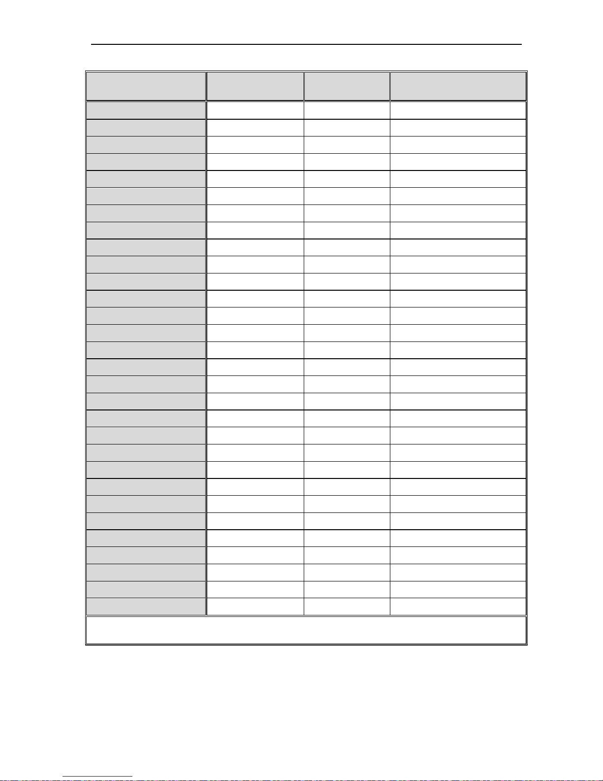
● 3-phase 380V machine main circuit wiring
Model
Main circuit terminals
screw specifications
Suggested fixed
moment (N·m)
Suggested Copper-core cable
specification mm
2
(AWG)
AC70-T3-R75G/1R5P M4
1.2~1.5
1.5mm2(14)
AC70-T3-1R5G/2R2P M4 1.2~1.5 2.5mm2(12)
AC70-T3-2R2G/004P M4
1.2~1.5
2.5mm2(12)
AC70-T3-004G/5R5P M4 1.2~1.5 4mm2(10)
AC70-T3-5R5G/7R5P M4
1.2~1.5
6mm2(9)
AC70-T3-7R5G/011P M5 2~2.5 6mm2(9)
AC70-T3-011G/015P M5
2~2.5
10mm2(7)
AC70-T3-015G/018P M6 4~6 10mm2(7)
AC70-T3-018G/022P M6
4~6
16mm2(5)
AC70-T3-022G/030P M8 8~10 16mm2(5)
AC70-T3-030G/037P M8
8~10
25mm2(3)
AC70-T3-037G/045P M8 8~10 25mm2(3)
AC70-T3-045G/055P M8
8~10
35mm2(2)
AC70-T3-055G/075P M10 11~13 35mm2(2)
AC70-T3-075G/093P M10
11~13
50mm2(1)
AC70-T3-093G/110P M10 11~13 50mm2(1/0)
AC70-T3-110G/132P M10
11~13
70mm2(2/0)
AC70-T3-132G/160P M10 11~13 95mm2(3/0)
AC70-T3-160G/185P M12
14~16
95mm2(4/0)
AC70-T3-185G/200P M12 14~16 120mm2
AC70-T3-200G/220P M12
14~16
150mm2
AC70-T3-220G/250P M12 14~16 150mm2
AC70-T3-250G/280P M12
14~16
185mm2
AC70-T3-280G/315P M12 14~16 185mm2
AC70-T3-315G/355P M16
20~23
240mm2
AC70-T3-355G/400P M16 20~23 240mm2
AC70-T3-400G/450P M16
20~23
300mm2
AC70-T3-450G/500P M16 20~23 400mm2
AC70-T3-500G/560P M16
20~23
400mm2
AC70-T3-560G/630P M16 20~23 500mm2
Note: Here we suggest to use copper joins as mains electric connectors of machine over 185KW. Pls refer the cut
section area above.
Table 3-7: Suggested cable diameter and fixed moment 3-phase 380V machine main circuit
AC70 VC CONTROL FREQUENCY INVERTER MANUAL INSTALLATION AND WIRING
28
● Single-phase 220V machine main circuit wiring
Model
Main circuit terminals
screw specifications
Suggested fixed
moment (N·m)
Suggested Copper-core cable
specification mm2 (AWG)
AC70-S2-R40G M4 1.2~1.5 1.5mm2(14)
AC70-S2-R75G M4 1.2~1.5 2.5mm2(12)
AC70-S2-1R5G M4 1.2~1.5 2.5mm2(12)
AC70-S2-2R2G M4 1.2~1.5 4mm2(10)
Table 3-8: Suggested cable diameter and fixed moment single-phase 220V machine main circuit
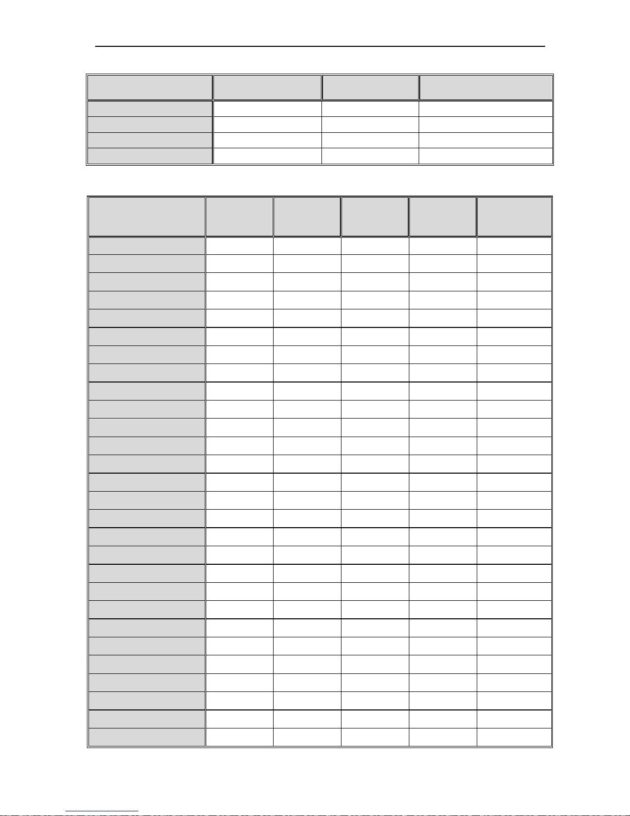
● Suggested main circuit components specification
Model
Contactor
specification
Breaker
specification
DC reactor Input filter Output filter
AC70-T3-R75G/1R5P 10A 10A ------ NFI-005 NFO-010
AC70-T3-1R5G/2R2P 10A 10A ------ NFI-005 NFO-010
AC70-T3-2R2G/004P 16A 15A ------ NFI-010 NFO-010
AC70-T3-004G/5R5P 16A 20A ------ NFI-010 NFO-010
AC70-T3-5R5G/7R5P 25A 20A ------ NFI-020 NFO-020
AC70-T3-7R5G/011P 25A 30A ------ NFI-020 NFO-020
AC70-T3-011G/015P 32A 40A ------ NFI-036 NFO-036
AC70-T3-015G/018P 40A 50A ------ NFI-036 NFO-036
AC70-T3-018G/022P 50A 60A ------ NFI-050 NFO-050
AC70-T3-022G/030P 50A 75A DCL-50 NFI-050 NFO-050
AC70-T3-030G/037P 63A 100A DCL-80 NFI-080 NFO-080
AC70-T3-037G/045P 80A 125A DCL-100 NFI-100 NFO-100
AC70-T3-045G/055P 100A 150A DCL-110 NFI-100 NFO-100
AC70-T3-055G/075P 125A 175A DCL-125 NFI-150 NFO-150
AC70-T3-075G/093P 160A 200A DCL-150 NFI-150 NFO-150
AC70-T3-093G/110P 220A 250A DCL-200 NFI-200 NFO-300
AC70-T3-110G/132P 220A 300A DCL-200 NFI-200 NFO-300
AC70-T3-132G/160P 250A 400A DCL-300 NFI-300 NFO-300
AC70-T3-160G/185P 300A 500A DCL-300 NFI-300 NFO-300
AC70-T3-185G/200P 400A 600A DCL-400 NFI-400 NFO-400
AC70-T3-200G/220P 400A 700A DCL-400 NFI-400 NFO-400
AC70-T3-220G/250P 630A 800A DCL-500 NFI-600 NFO-600
AC70-T3-250G/280P 630A 1000A DCL-600 NFI-600 NFO-600
AC70-T3-280G/315P 630A 1200A DCL-600 NFI-600 NFO-600
AC70-T3-315G/355P 630A 1200A DCL-800 ------ -----AC70-T3-355G/400P 800A 1400A DCL-800 ------ -----AC70-T3-400G/450P 1000A 1600A DCL-1000 ------ -----AC70-T3-450G/500P 1000A 2000A DCL-1000 ------ ------
 Loading...