

Veichi AC300-T3-2R2G, AC300-T3-5R5G, AC300-T3-1R5G, AC300-T3-011G, AC300-T3-018G Technical Manual
...
CONTENT
CHAPTER1OVERVIEW...................................................................................1
CHAPTER2BEFOREUSE.................................................................................7
CHAPTER3INSTALLATIONANDWIRING.........................................................9
CHAPTER4BASICOPERATIONANDTRIALRUN.............................................30
CHAPTER5FAULT DIAGNOSESANDPROCESSING..........................................33
CHAPTER6PERIODICOVERHAULANDMAINTENANCE.................................44
CHAPTER7PERIPHERALEQUIPMENTSANDOPTIONS...................................48
CHAPTER8FUNCTIONPAR AM E TE R SPECIFICATIONS....................................53
CHAPTER9FUNCTIONPAR AM E TE R TABLE..................................................149
APPENDIX1:AC300IOEXPANSIONCARDMANUAL....................................177
APPENDIX2:PGCARDMANUAL................................................................181
AC300 Series Vector Control Inverter Manual Overview
1
Chapter 1 Overview
Thanks for purchasing the AC300 series vector control inverter which designed and manufactured by VEICHI Electric.
This manual describes how to use this product correctly for good returns. Please read this manual carefully before
using the product (installation, wiring, operation, maintenance, inspection, etc.). In addition, please use this product
after fully understanding the safety precautions described in this manual.
1.1 Safety requirement and cautions
Please use the product after fully understanding the safety precautions described in this manual to ensure safe,
reliable and reasonable use of this product.
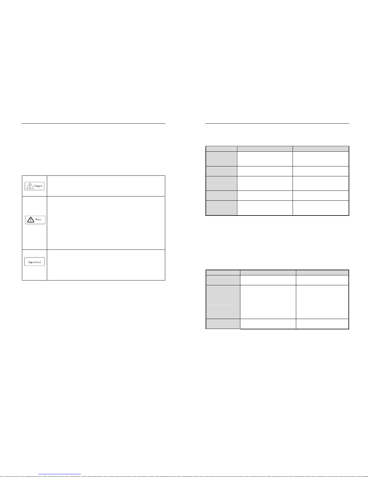
Warning signs and meanings
This manual has used following signs which means there is an important part of security. While observing against the
rules, there is a danger of injury even death or machine system damage.
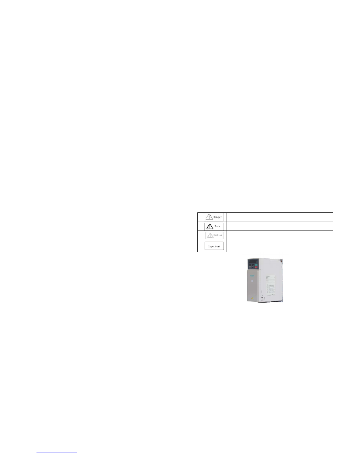
Danger: Wrong operation may cause death or large accident.
Warni ng: Wrong operation may cause death or large safety incident.
Caution: Wrong operation may cause minor wound.
Important: Wrong operation may cause damage to this product and associated systems.
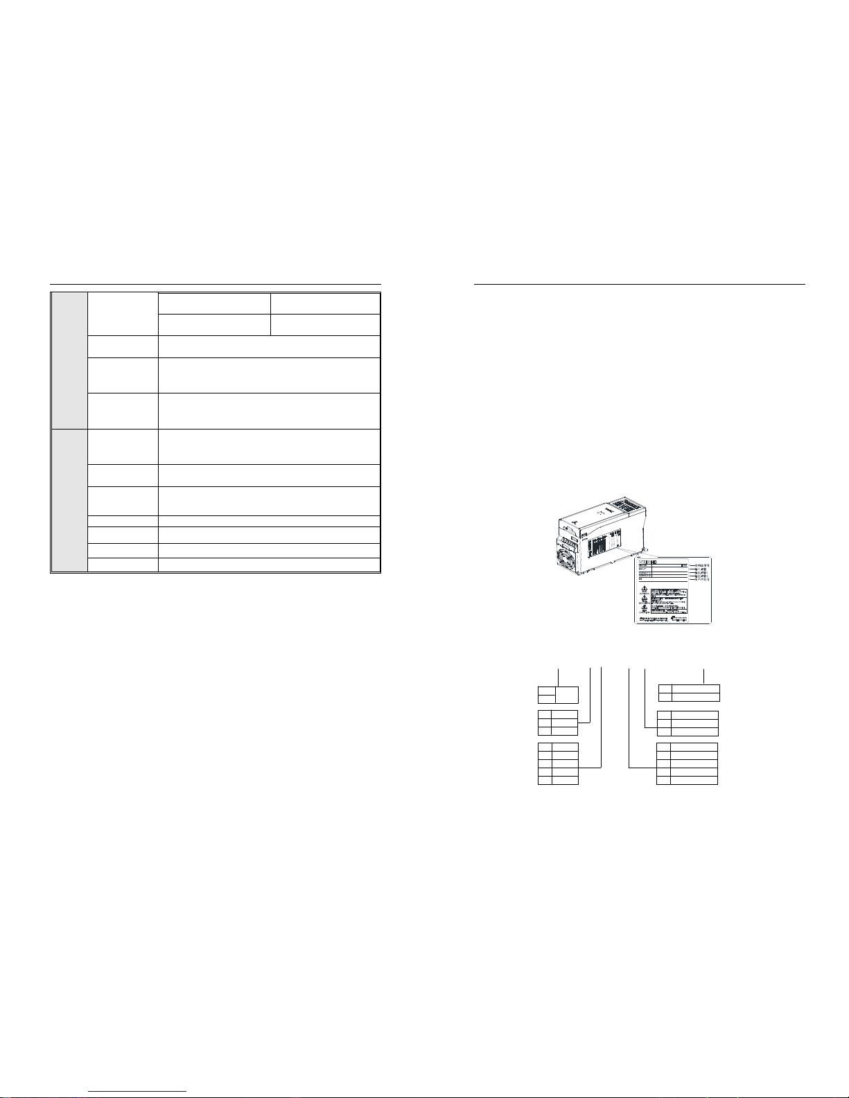
Figure 1-1 AC300 series inverter shell warning mark position
Operation requirement
Only professionally trained persons can be allowed to operate the equipment. “Professional trained persons “means
the workers must have experience professional trained skill, and must be familiar with installation, wiring, running and
AC300 Series Vector Control Inverter Manual Overview
2
maintain and can rightly deal with emergency cases in use.
Safety guidance
Safety rules and warning signs come for your security. They are measures to prevent the operator and machine
system from damage. Please carefully read this manual before using and strictly observe the regulations and warning
signs while operating. Safety rules and warning signs are divided into the following categories: general guidance,
guidance for transportation and storage, instructions for installation wiring, instructions for operation, instructions for
maintenance, and guidance for disassembly and disposal.
General guidance
This product carries dangerous voltage and controls driver machine with potential
danger. If you don’t abide by the regulations or requirements in this manual, there
is danger of body injury even death and machine system damage.
Only trained personnel are allowed to operate this product. Before using this
product, please be familiar with all the safety and operating instructions in this
manual. Correct operation and maintenance is a reliable guarantee of this product.
Do not wire while the power is connected. Otherwise, there is danger of death for
electric shock. Before wiring, inspection and maintenance, please cut off power
supply of all related equipment’s and ensure main DC voltage in safe range. And
please operate it after 5 mins.
Prevent children and the public from near the product.
This product can only be used in accordance with the manufacturer's intended,
and may not be used in special fields such as emergency, rescue, shipbuilding,
medical, aviation, nuclear facilities, etc. without permission.
Unauthorized modifications and use of spare parts recommended by the
manufacturer of this product may result faults.
Be sure to deliver this manual to the actual user so that the actual user can read
this manual carefully before use.
Before installing and debugging the inverter, please be sure to read and fully
understand these safety rules and warning signs.
Transportation and storage instructions
Correct transportation, store, installation, careful operation and maintenance are
important for inverter safe operation.
In transport and store process, make sure the inverter is free from impact and
vibration. It must be stored where is dry without corrosive air and conductive dust,
and the temperature must be lower than 60℃.
Guide to installing wiring
AC300 series vector control inverter manual Overview
3
Only trained professionals can operate this product.
Power wire, motor wire and control wire should be all connected firmly. Earth
must be reliable and earth resistance must be lower than 10Ω.
Before turning on the inverter panel, please cut off the power of all related
equipment and confirm that the DC voltage of the main circuit has dropped to a
safe level. Wait for 5 minutes before related operations.
Human body electrostatic will damage inner sensitive components seriously.
Before operation, please follow ESD measures. Otherwise, there is danger of
inverter damage.
Inverter output voltage is pulse wave. If components such as capacitor which
improves power factor and pressure-sensitive resistance for anti-thunder and
so on are installed at the output side, please dismantle them or change to input
side.
No switch components such as breaker and contactor at the output side (If
there must be one, please make sure the output current is 0 while the switch
acting).
● The power cable and motor cable specifications which connected to the inverter
must meet the conditions shown in Table 3-7 3-8 of this manual.
Operational guidance
The frequency inverter operation at high voltages , dangerous voltages are
inevitably present on certain parts of the product.
Regardless of where the fault occurs in the control device, it can cause major
accidents or even personal injury and potentially dangerous faults. Therefore,
additional external precautions or other means for ensuring safe operation must
be taken, for example: Install independent current limiting switch, mechanical
protection and other devices.
In order to ensure that the overload protection of the motor can operate correctly,
the motor parameters of the input inverter must be similar to the actual motor .
Maintenance guidance
Only Veichi Electric co., ltd service department or its authorized service center
can maintain the products. It may cause product fault while using accessories
not authorized or permitted.
Any defective components must be changed in time in maintenance.
Before turning on the equipment for maintenance, make sure to disconnect the
power supply and confirm that the DC voltage of the main circuit has dropped to
a safe level. Wait 5 minutes before related work.
AC300 series vector control inverter manual Overview
4
Guidance on disassembly and waste disposal
The package of the inverter can be reused. Please keep the package for future
use or return it to the manufacturer.
The removed metal parts can recyclable.
Some devices may badly affect the environment, such as electrolytic capacitors,
please handle devices in accordance with the requirements of the environmental
protection department.
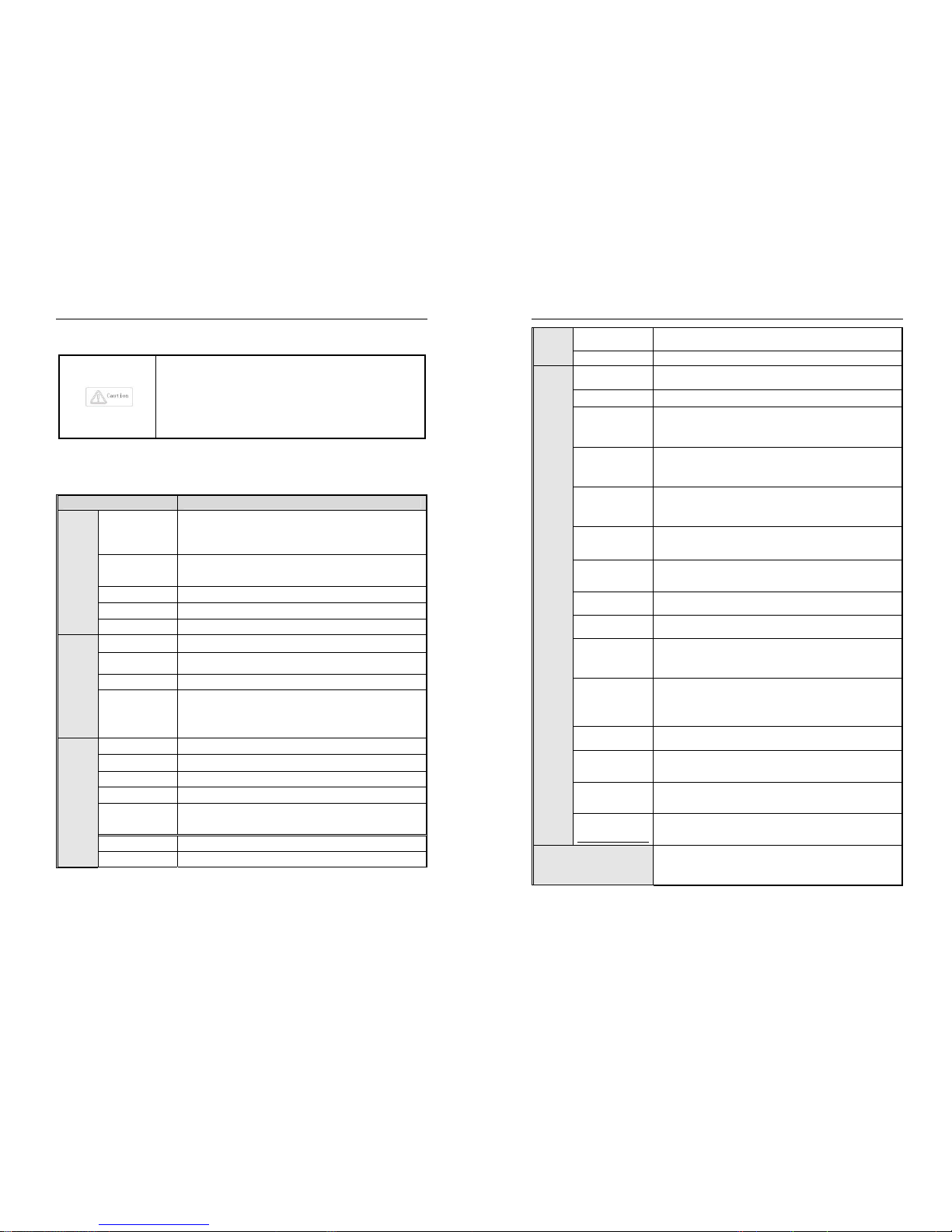
1.2 Technical Specifications
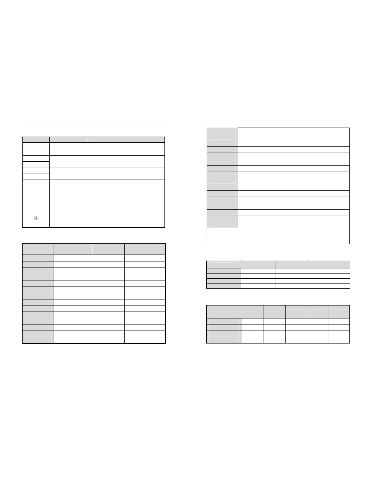
Table 1-1: Technical Specifications
Items Specifications
Powerin
put
Voltage, frequency
Single phase 220V 50/60Hz Three phase 380V 50/60Hz
Three phase 220V 50/60Hz Three phase 660V 50/60Hz
Three phase 1140V 50/60Hz Three phase 480V 50/60Hz
Allowable fluctuations
voltage unbalance rate:<3%; Frequency:±5%; aberration rate: as
IEC61800-2 required
Inrush current Lower than rated current
Power factor ≥0.94(with DC reactor)
Efficiency ≥96%
Output
Output voltage Output under rated condition: 3 phase, 0~input voltage, inaccuracy<5%
Output frequency
range
G/P type:0~600Hz
Output frequency
Max frequency ±0.5%
Overload capacity
G type: 150% rated current/1 min, 180% rated current/10s, 200% rated
current/0.5s
P type: 120% rated current/1 min, 140% rated current/10s, 150% rated
current/0.5s
Main
Controlper
formance
Motor control mode V/F without PG , VC without PG, V/F with PG, VC with PG
Modulation mode Optimized SVPWM mode
Carrier frequency
0.7~16.0kHz
Speed control range VC without PG: rated load 1:100; VC with PG: rated load 1:1000
Steady speed
accuracy
VC without PG: ≤2% rated synchronized speed; VC with PG: ≤0.05% rated
synchronized speed
Starting torque
VC without PG: when 0.5Hz, 150% rated torque; VC with PG: when 0Hz,
Torque response VC without PG: ≤20ms; VC with PG: ≤10ms
AC300 series vector control inverter manual Overview
5
Frequency accuracy Digit setting: max frequency×±0.01%; Analog setting: max frequency×±0.2%
Frequency resolution Digit setting: 0.01Hz; Analog setting: max frequency×0.05%
Basic
functions
DC braking capacity
Starting frequency:0.00~50.00Hz; Braking time:0.0~60.0s; Braking
current:0.0~150.0% rated current
Torque boost
Auto torque upgrade 0.0%~100.0%; Manual torque upgrade 0.0%~30.0%
V/F curve
4 modes: one linearity torque characteristic curve ,one self-setting V/F curve
mode, one drop torque characteristic curve (1.1- 2.0 powers),and square V/F
curve mode.
Acceleration/Deceler
ation curve
2 modes: linear Acceleration/Deceleration and S curve
Acceleration/Deceleration. 4 sets of ACC/DEC, time unit 0.01s selectable,
longest time: 650.00s.
Rated output voltage
Rely on power supply voltage compensate function, while motor rated
voltage is 100%, set it at the range of 50-100%(output can not over input
voltage).
Voltage
auto-adjustment
While power supply voltage fluctuates, it can auto-keep constant output
voltage.
Auto energy-saving
running
While under V/F control mode, according to load situation, auto-optimize
output voltage to save energy.
Auto-limit current Auto-limit the current while running to prevent over current break trouble.
Instant power off
treatment
While instant power off, realize continual operation by bus voltage control.
Standard functions
PID control, speed track, power off restart, jump frequency, upper/lower
frequency limit control, program operation, multi- speed, RS485, analog
output, frequency impulse output.
Frequency setting
channels
Keyboard digital setting, Analog voltage/current terminal AI1, Analog
voltage/current terminal AI2, Communication given and multi-channel
terminal selection, Main and auxiliary channel combination, expansion card,
supporting different modes switch
Feedback input
channel
Voltage/Current Terminal AI1, Voltage/Current Terminal AI12, Communication
given, Low-speed pulse input PUL, extension card
Running command
channel
Operation panel given, external terminal given, communication given,
expansion card given
Input command
signal
Start, stop, FWD/REV, JOG, multi-step speed, free stop, reset, ACC/DEC
time selection, frequency given channel selection, exterior fault alarm.
Exterior output
signal
1 relay output, 1 collector output, 1 AO output: 0~10V output or 4~20mA
output, or frequency pulse output
Protection function
Overvoltage, under-voltage, current limit, over-current, overload, electric
thermal relay, overheat, overvoltage stall, data protection, rapid speed
protection, input/output phase failure protection
AC300 series vector control inverter manual Overview
6
Keyboar
d display
LED display
Single file 5 digital tube display Can monitor one state variable
Two file 5 digital tube display Can monitor two state variables
Parameter copy
Can upload or download function code information of inverter to realize fast
parameter copy.
State monitor
Output frequency, given frequency, output current, input voltage, output
voltage, motor speed, PID feedback, PID given value, module temperature
etc. monitor parameters.
Fault alarm
,Over-voltage, under-voltage, over-current, short circuit, phase failure,
overload, overheat, overvoltage stall, current limit, or data protection
destroyed; Fault running state; Fault history.
Environ
ment
Install place
altitude ≤ 1000m,above 1000m down the rated amount, each increase of
100m down the rated amount of 1%;no condensation, ice ,rain, snow, hail;
solar radiation below 700W/㎡, air pressure 70-106 kPa
Temperature,
humidity
-10~+50℃, above 40℃ down the rated amount, the max temperature:60℃
(no load running)
Vibration
9~200Hz,5.9m/s2(0.6g)
5%—95%RH (no condensation)
Store temperature -30—+60℃
Installation Hanging type, cabinet type
Protection degree IP20
Cooling mode Forced air cooling
AC300 Series Vector Control Inverter Manual Before Use
7
Chapter 2 Before Use
2.1 Purchase Inspection
On receiving your order, please check the package and confirm intact before opening, and check if there’s any
damage, scratch or dirt (damages caused during transportation are not within the company's warranty). If there’s any
damage caused during transportation, please contact us or the transport company immediately.
After confirming the receipt of the goods intact, please re-confirm if the product and your order are consistent. Model
of the product is on the "MODEL" column. If you find the product model is not the one you ordered, please contact the
dealer you purchased the product or the sales department of VEICHI immediately.
2.2 Nameplate
Nameplate Position and Content
Model Specification
Series
-
B
Code
V-level
2
220V
3
380V
6 660V
Code
V-Level
T
Tri-phase
S
One-phase
Code Inverter Type
G
Heavy load
Code
motor power(KW)
7R5
011
7.5
11
018
132
18.5
132
11
1140V
A
C300
P
Light load
Code
Code Accessory Type
B
Brake unit
AC300
T 3
- 011 G /015P-
AC300 Series Vector Control Inverter Manual Before Use
8
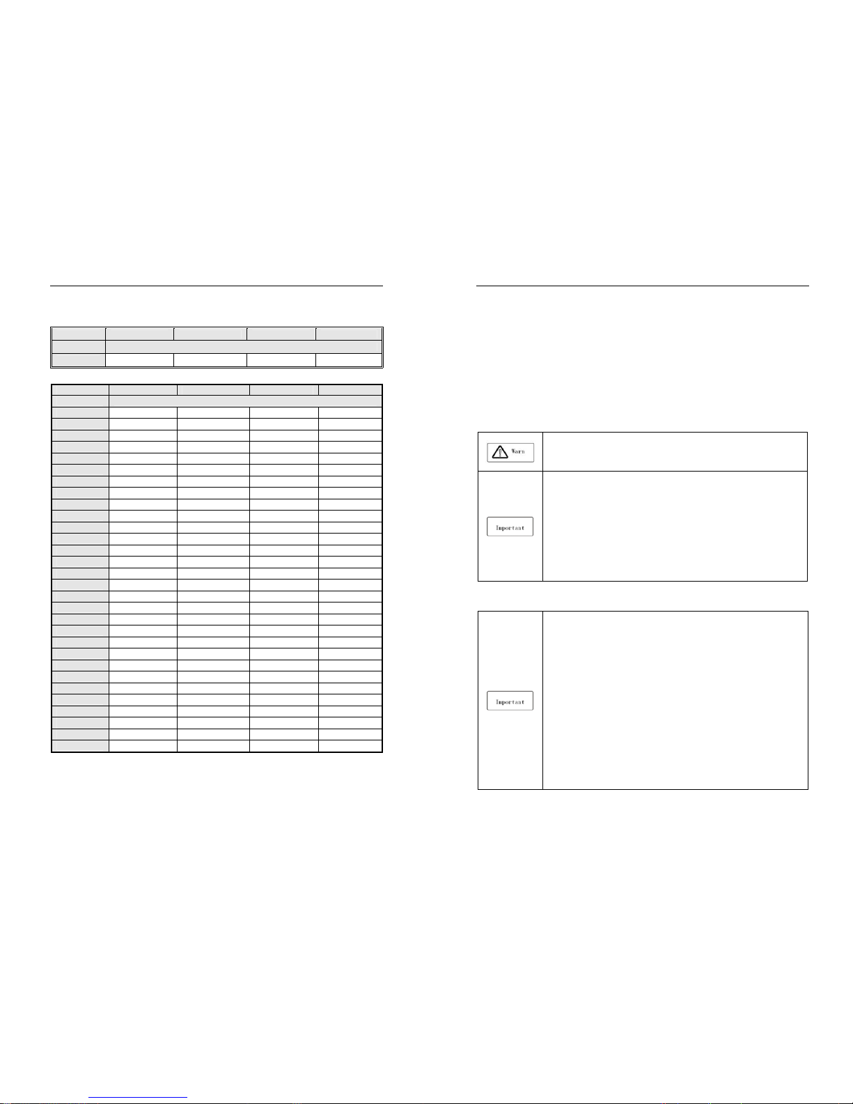
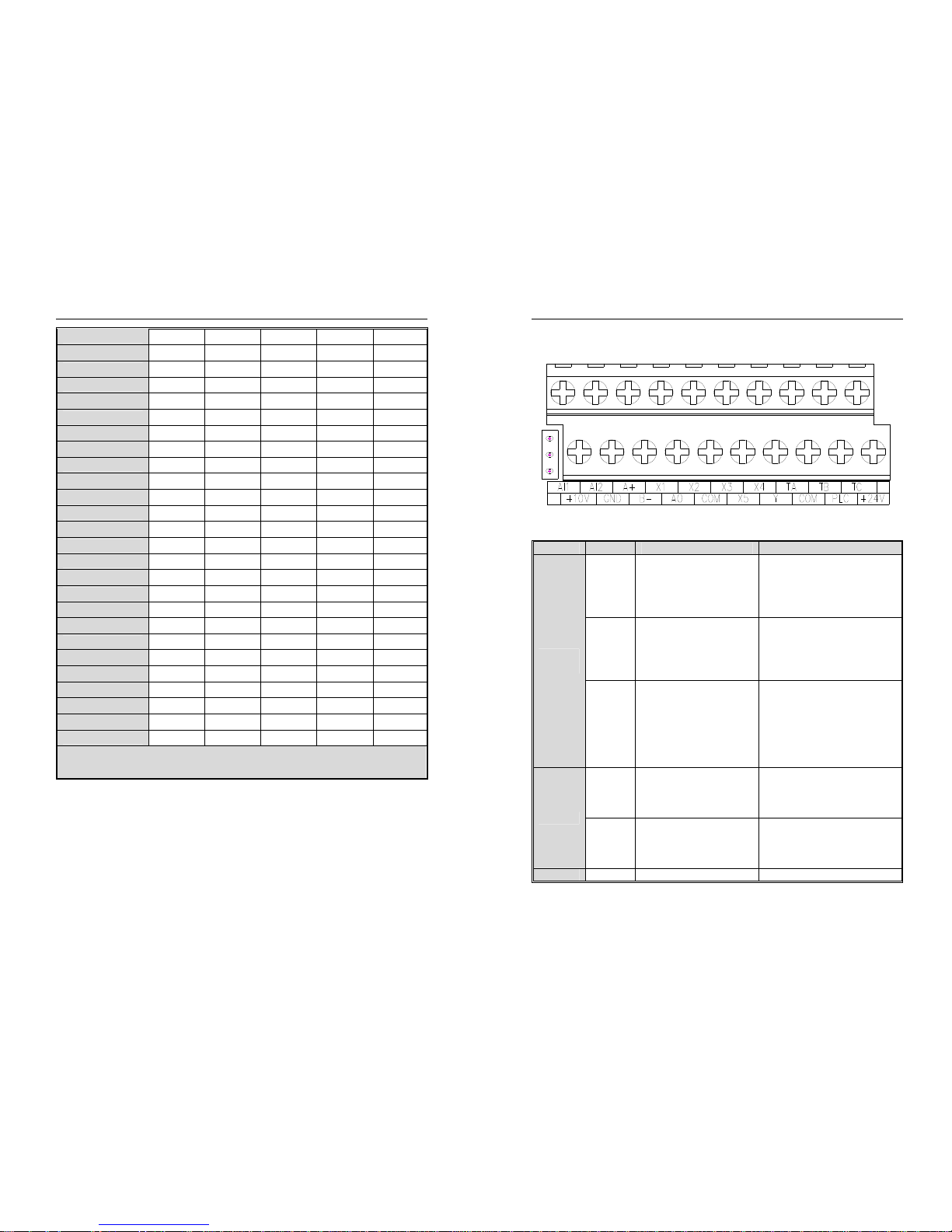
2.3 Inverter Rated Output Current
Input Voltage 220V 380V 660V 1140V
Rated Power Rated Output Current (A)
0.75 4 3
Input Voltage 220V 380V 660V 1140 V
Rated Power Rated Output Current (A)
1.5 7 4
2.2 10 6.0
4 16 10
5.5 20 13
7.5 30 17 10
11 42 25 15
15 55 32 18
18.5 70 38 22
22 80 45 28
30 110 60 35
37 130 75 45 25
45 160 90 52 31
55 200 110 63 38
75 260 150 86 52
90 320 180 98 58
110 380 210 121 75
132 420 250 150 86
160 550 310 175 105
185 600 340 198 115
200 660 380 218 132
220 720 415 235 144
250 470 270 162
280 510 330 175
315 600 345 208
355 670 380 220
400 750 430 260
450 810 466 270
500
860 540 325
560 990 600 365
630 1100 680 400
AC300 Series Vector Control Inverter Manual Installation and Wiring
9
Chapter 3 Installation and Wiring
3.1 Safety Precautions
This chapter explains the warnings that must be followed to ensure that the user can safely use the product,
maximize the performance of the inverter, and ensure reliable operation of the inverter.
Cautions in use
:
● While install the inverter in the closed cabinet, please build in cooling fan, air-conditioner
or other cooling equipment to ensure the temperature at the air-in port below 40℃. So that
the inverter can work safely and reliably.
● While installing, please use cloth or paper cover the inverter to prevent metal dust, oil,
water and others.And remove it carefully after working.
● While operation, please follow the ESD regulations. Otherwise, the inverter may be
damaged.
● While multi inverters are installed in the same cabinet, enough space must be left for
cooling fan.
● Inverter cannot work over rated range. Otherwise, the inverter may be damaged.
● While transporting the inverter, please hold the firm case. If only hold the pre-cover, there
is danger of inverter main body falling, injury or inverter damage.
Cautions in use motor
● Different motor has different max allowable running speed. Motor can not run over the
max allowable running speed.
● While inverter is running at low speed, the motor auto-cool effect is seriously worse. If
motor runs at low speed for long time, it will be damaged for overheat. If needed, please use
special motor for inverter.
● While constant speed machinery runs at inconstant speed, there maybe sympathetic
vibration. Please install vibration-proof rubber under motor rack or use jumping frequency
control function.
● While using frequency inverter or working frequency power supply to drive, the torque
characteristic are different. Please do confirm the torque characteristic of the equipment
connected.
● The rated current of diving motor is higher than that of standard motor, please confirm it
and choose the right inverter.
● While the wire between motor and inverter is long, the max torque of the motor will reduce
for voltage drop. So please use thick cable while the distance between the motor and the
inverter is long.
AC300 Series Vector Control Inverter Manual Installation and Wiring
10
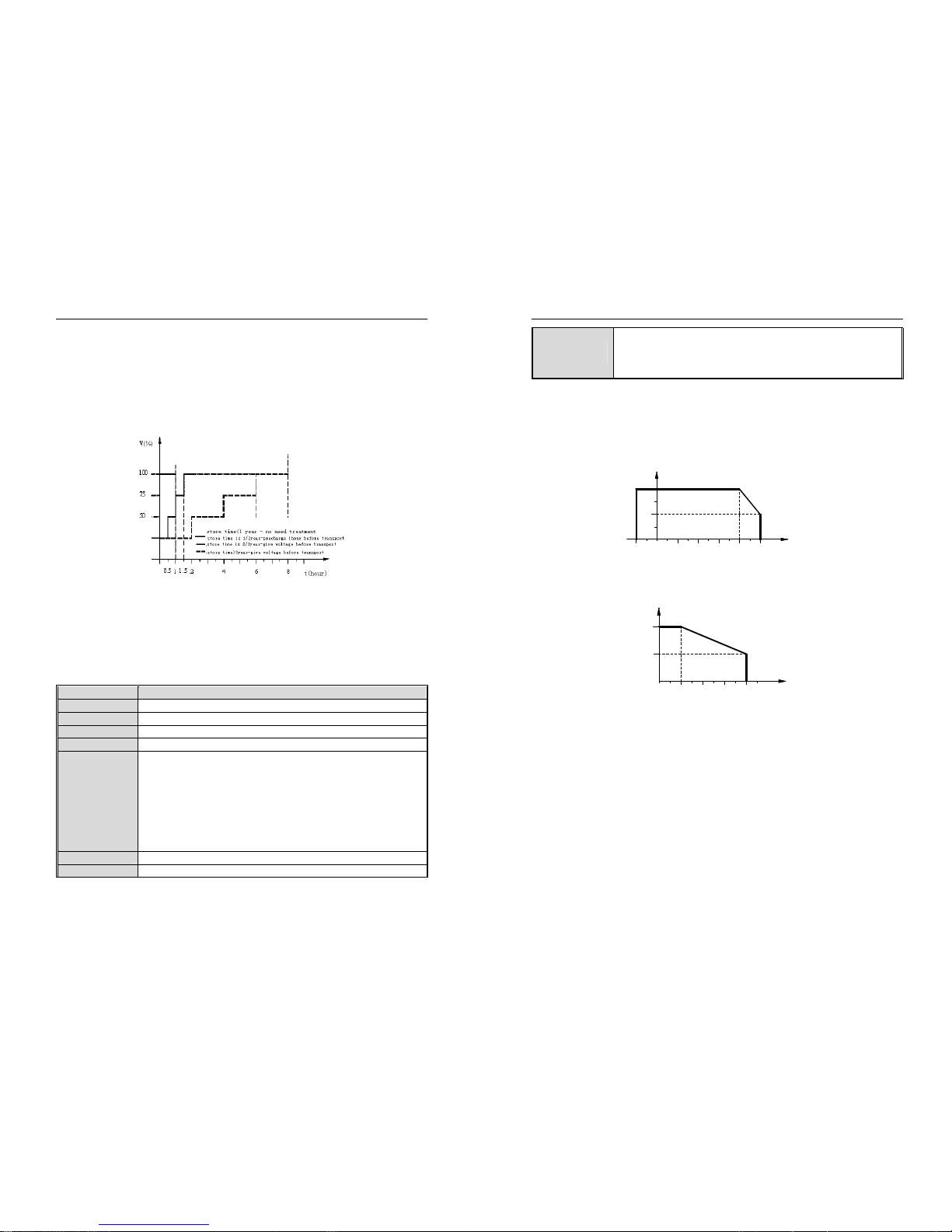
3.2 Treatment for Inverter after Longtime Store
If the inverter store time is over one year, you must pre-charge the aluminum capacitor in the inverter again and
install the inverter after the aluminum capacitor characteristic recovering. For the specific method, please follow the
grads in the chart below and give corresponding proportional voltage for every grad more than 30 mins while the
inverter is no-load.
If the input voltage of one grad is at the action critical point of contactor, fan or other equipment, please increase or
reduce the corresponding input voltage for the grad to avoid any component working under critical state.
Chart 3-1: treatment for inverter after longtime store
3.3 Inverter Stable Running Environment
Installation environment is very important to the best use of this product for long time. Pls install this product in the
environment as the following table requirement.
Table 3-1: Environmental conditions required for reliable operation of AC300 series inverters
Environment Requirement
Install place Indoor without direct sunshine
Install temperature -10 ~ +40℃
Store temperature -30 ~ +60℃
Humidity <95%RH, no condensation
Surrounding
Please install the inverter in place as follows:
● Place without oil mist, corrosive gases, flammable gas, dust or etc.
● Place without metal dust, oil, water or etc into inverter (please do not install inverter on
flammable material such as food and etc).
● Place without radioactive material or flammable material.
● Place without poisonous gases or liquid.
● Place with very little salification erosion.
● Place without direct sunshine.
Altitude <1000m, down power for use over 1000 meters
Vibration At 9 to 200 Hz, 5.9 m/s2 (0.6 g)
AC300 Series Vector Control Inverter Manual Installation and Wiring
11
Installation and
cooling
● Inverter can not be installed horizontally must be installed vertically.
● Please independently install high heating equipment such as braking resistor and etc
which can not be installed in the same cabinet with inverter, installed at the air-in port of
the inverter is strictly prohibited.
● In order to improve the product stability, do please not use the inverter where temperature changes sharply. While
using in closed space such as control cabinet, please use cooling fan or air-condition to cool inverter to avoid
temperature over limit range. Please also prevent inverter from freeze, too low temperature may cause components
freeze fault.
● Derate according to the chart while over temperature limit.
30
25
100
75
50
402010
0
-10 50
TEMPERATURE(℃)
PERMIT OUTPUT CURRENT(%)
Chart 3-2:AC300 series inverter derating curve while over permit temperature
● Derate according to the chart while over altitude limit.
0
1000 2000 4000
80
100
3000 ALTITUDE(M)
PERMIT OUTPUT CURRENT(%)
Chart 3-3:AC300 series inverter derating curve while over permit altitude
3.4 EMI Protection
The inverter is designed to be used in industrial environment with strong electromagnetic interference. Generally
speaking, if the installation quality is good, it is ensured that the inverter can work safely without fault. Please install the
inverter according to the following rules to ensure stable running and avoid electromagnetic interference impact.
● Ensure that all equipment in the cabinet have been connected reliably to the common Y-type earth point or earth
bus with thick and short cable. The motor earth should be as close as possible. Please do not connect the motor case
to the inverter earth terminal or the protective area of control system.
● Ensure that all equipment connected to the inverter have been reliably connected to the same earth net or Y-type
earth point with thick and short cable.
● The conductor has better to be flat and with multi core, what has lower resistance at high frequency.
AC300 Series Vector Control Inverter Manual Installation and Wiring
12
● The cutting terminal should be as soigne as possible. Unshielded wire section must be as short as possible.
● In control cable wiring, it should be as far from the power supply cable and motor cable as possible. And
independent cable trough should be used. While the control cable must cross to the power supply cable or motor cable,
it should be 90º vertical cross.
● Ensure that the contactor in the cabinet has wave surge suppresser. Or‘R-C’damping circuit is connected to the
winding of AC contactor. Voltage dependent resistor corresponding to the winding voltage is used. And freewheel diode
or components such as voltage dependent resistor corresponding to the winding voltage are connected to DC contactor.
It is very important while contactor, controlled by output relay of inverter, acts frequently.
● Cable connected to motor should be shielded cable or armoured cable. The two barriers are earthed reliably by
cable grounding card.
● Build noise filters at the input side to reduce electromagnetic interference from other equipments at the power grid
side. The noise filter should be as close to the inverter power input terminal as possible. Meantime, the filter must earth
reliably as the inverter.
● Build noise filters at the output side to reduce radio interference and inductive disturbance. The noise filter must be
as close to the inverter output terminal as possible. Meantime, the filter must earth reliably as the inverter.
● Anytime, control circuit wire should be shielded cable.
● Add zero phase reactor in power supply wire near inverter input terminal and add zero phase reactor in the motor
wire near inverter output terminal to reduce electromagnetic interference to the inverter efficiently.
● Earthing Right and reliable earthing is the basic condition of safe and reliable running of the product. For right
earthing, please read the following notice carefully.
● In order to avoid electric shock, earthing cable should be the size as electric
equipment technique standard required and cable length should be as short as
possible. Otherwise, inverter leakage current will cause unstable potential of the
earthing terminal which is far from the earthing point, and electric shock accident will
happen frequently.
● Earth terminal must be earthing. Earth resistance must be below 10Ω.
Otherwise, there is danger of death.
● Please do not share earth cable with welder or other big current/pulse power
equipment. Otherwise, inverter will act abnormally.
● While multi inverters are used at the same time, please do not wind the earth
wire to loop-type. Otherwise, inverter will act abnormally.
AC300 Series Vector Control Inverter Manual Installation and Wiring
13
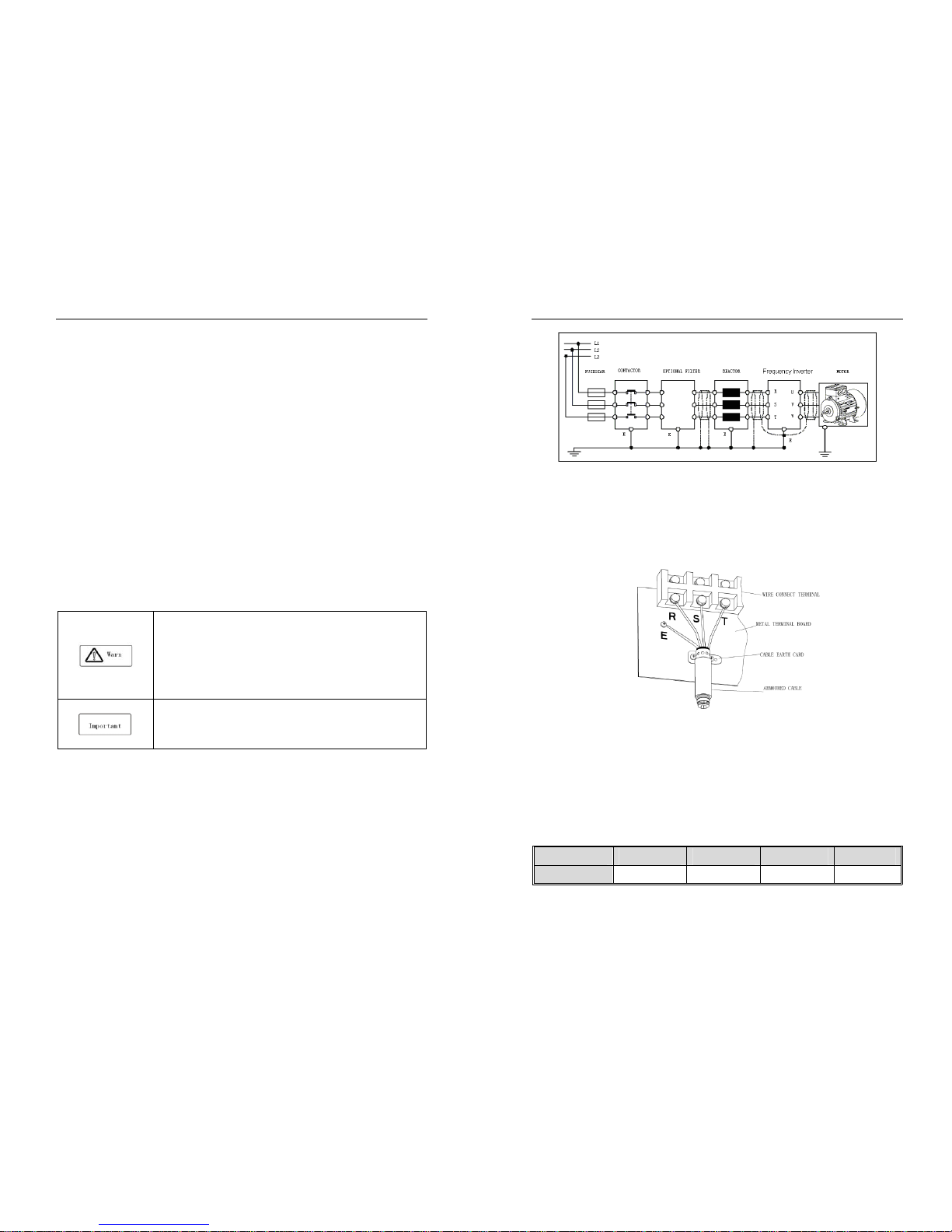
Chart 3-4:AC300 series inverter system grounding
Remark: motor must earth as close as possible. Motor case can not be connected to the inner earth terminal of the
inverter. It also can not share the earth net with the control system.
Shield of inverter power cable, motor cable and control cable
Shielding layer (reticulate/armoured) should be winded reliably by cable earth card and fix to inverter earth piece by
bolt. Please refer to the following chart.
Chart 3-5: Cable earth card for cables grounding
Corresponding relationship between inverter/motor cable length and carrier frequency
While cable distance between inverter and motor is long (especially low frequency output), cable voltage drop will
make motor torque reduce. Further more, cable HF leakage current will increase. Then inverter output current will
increase, that will cause inverter over-current trip. The current detection accuracy and running stability will be impacted.
Please follow as below table to adjust carrier frequency according to the cable length. While the cable distance is over
100m, please adopt distributed capacity reduce measure (Such as “no metal conductor covers cable”, “wire each phase
cable apart” and so on).
Table 3-2: Corresponding relationship between inverter/motor cable length and carrier frequency
Cable length <20m 20~50m 50~100m >100m
Carrier frequency 0.7~16kHz 0.7~8kHz 0.7~4kHz 0.7~2kHz
AC300 Series Vector Control Inverter Manual Installation and Wiring
14
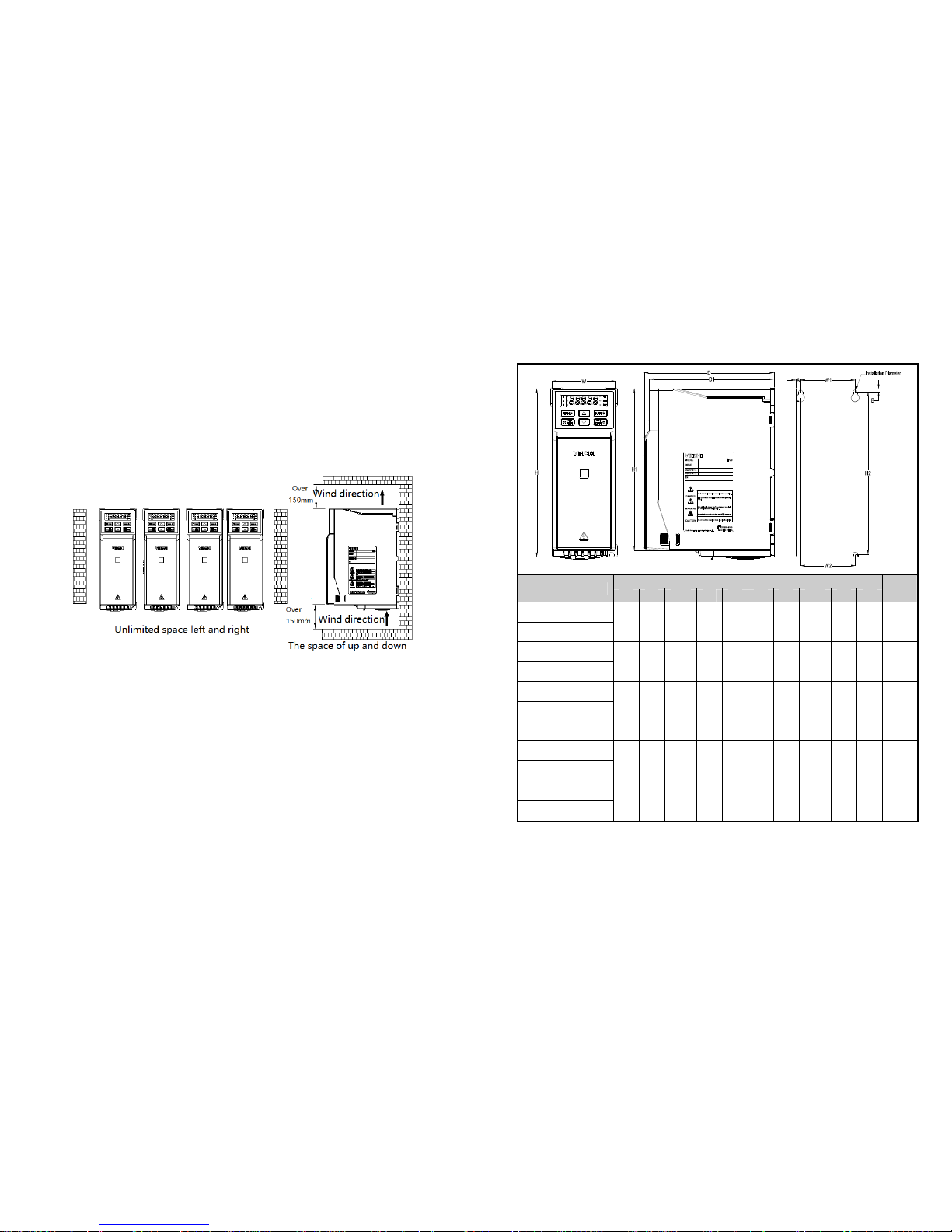
3.5 Machinery Installation
Installation notice and related requirement:
● Installation direction
To prevent inverter cooling effect reducing, please do install the inverter vertically.
● Installation space
Single machine installation: to ensure enough ventilation and wiring space for inverter cooling, please follow
installation conditions as follows. The back of the inverter should stick to the wall. So that the surrounding air of radiator
can flow freely to ensure the cooling effect.
Chart 3-6: Inverters paratactic installation space requirement
AC300 Series Vector Control Inverter Manual Installation and Wiring
15
Dimension of Inverter and Keyboard
MODEL
Overall Dimension(mm) Installation Dimension(mm)
Apertu
re
W H H1 D D1 W1 W2 H2 A B
AC300-T/S2-R75G-B
76 200 192 155 149 65 65 193 5.5 4 ф3-M4
AC300- T/S2-1R5G-B
AC300- T/S2-2R2G-B
100 242 231 155 149 84
86.
5
231.5 8 5.5 ф3-M4
AC300- T/S2-004G-B
AC300-T3-R75G/1R5P-B
76 200 192 155 149 65 65 193 5.5 4 ф3-M4 AC300-T3-1R5G/2R2P-B
AC300-T3-2R2G-B
AC300-T3-004G/5R5P-B
100 242 231 155 149 84
86.
5
231.5 8 5.5 ф3-M4
AC300-T3-5R5G/7R5P-B
AC300-T3-7R5G/011P-B
116 320 307.5 175 169 98 100 307.5 9 6 ф3-M5
AC300-T3-011G/015P-B
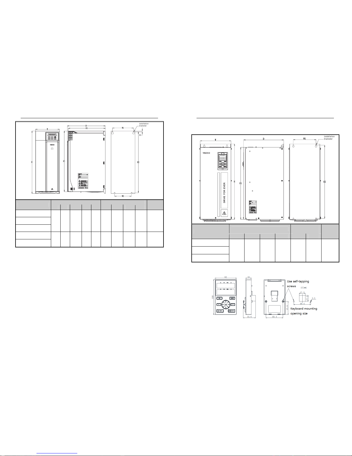
AC300 Series Vector Control Inverter Manual Installation and Wiring
16
MODEL
Overall Dimension(mm) Installation Dimension(mm)
Aperture
W H H1 D D1 W1 W2 H2 B
AC300-T3-015G/018P -B
142 383 372 225 219 125 100 372 6 ф4-M5 AC300-T3-018G/022P-B
AC300-T3-022G/030P-B
AC300-T3-30G/037P
172 430 / 255 219 150 150 416.5 7.5 ф4-M5
AC300-T3-037G/045P
AC300 Series Vector Control Inverter Manual Installation and Wiring
17
Overall Dimension of Inverter (Steel)
MODEL
Overall Dimension(mm)
Installation
Dimension(mm)
Aperture
W H H1 D W1 H2
AC300-T3-045G/055P
240 560 535 310 176 544 ф4-M6 AC300-T3-055G/075P
AC300-T3-075G/090P
External keyboard shape and opening size
Note: LCD is fully compatible with LED keyboard size and opening size.
AC300 series keyboard and opening size
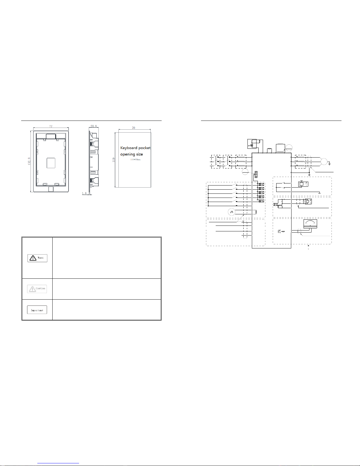
AC300 Series Vector Control Inverter Manual Installation and Wiring
18
AC300 Keyboard pocket opening size
3.6 Electric Installation
This chapter explains the regulations that users have to obey to ensure safe use, best performance and reliable
running.
Safety precaution
● Must earth reliably while inverter is running. Otherwise there is danger of casualty and
unstable inverter performance.
● To ensure safe running, only trained professional person can do installation and wiring
job.
● No operation under power connected state. Otherwise there is danger of electric shock
even death.
● Before operation, please cut all related equipments power, ensure that the main circuit
DC current has dropped to safe range. And please operate after 5 mins.
● Control cable, power cable and motor cable must be separated. They can not be in the
same cable trough or cable rack.
● This equipment can only be used as the maker states. Please consult Veichi while
using in special case.
● No insulation test for the inverter or the related cable by HV insulation test equipment.
● If the inverter or the peripheral equipment (filer, reactor and etc) needs insulation test,
firstly 500V megohmmeter should be used to test the insulation resistance which
should not be lower than 4MΩ.
AC300 Series Vector Control Inverter Manual Installation and Wiring
19
Standard Connection Diagram
Note2
Note:Function description in brackets is
factory default
Note1
Analog monitoring
signal output
TA
TB
TC
+24V
Y
Shielded cable (the
end close to VFD
grounding)
_
mA
2
0
10
0
-
+
V
W
U
M
~
Shielded cable or armoured cable
(the end close to VFD grounding)
E
(The grounding resistance
is less than 10 ohms)
W
V
U
Output Rector
External DC Rector
External
Brake
Resistor
Short
Piece
P1
+
( )
R
External Brake Unit
+10V
Frequency control input
R
T
S
AC POWER INPUT
GND
AI1
AI2
Shielded cable (the end close to
VFD grounding)
Multi function contact input
(REV JOG)
(FWD JOG)
(Reverse)
(Forward)
(Free STOP)
COM
X3
X4
X5
X1
X2
PB
( )+(-)
VFD
S
T
R
GND
A0
Coil
COM
Passive contact
output
AC220V
AC0V
Coil
MAX Output Of Contact:
3A/240VAC
5A/30VDC
1.MAX Output of +24V Port:DC24V/100mA
Note:When output type of AO port as
frequency and Voltage,
Maximum Output:2mA
2.Inner resistance of AI1/AI2 Port
1.MAX Output of +10V port :50mANote:
2.Max Output of Y Port :DC24V/50mA
Note:
represent control circuit terminals.
represent main circuit terminals;
Legend:
1.Symbol
Shielded cable
(the end close
to VFD grounding)
Input Rector
ContactorMCCB
+
( )
PUL
+24V
PLC
COM
Analog Voltage/Current quantity input
A+
B-
RS485 Differential
Communication
120Ω
Open collector(OC)
state output
Analog Voltage/Current quantity input
2.Symbol
Chart 3-8:AC300 series inverter standard diagram
Note:
When installing DC reactor, make sure to dismantle the short connector between terminal P1 and (+).
NPN or PNP transistor signal can be selected as input of multi-function input terminal (X1~X5/PUL) .
Inverter built-in power supply (+24V terminal) or external power supply (PLC terminal) can be chosen as
bias voltage. Factory setting ‘+24V’ short connect with ‘PLC’, which locates between RJ45 and
terminals.
● Auxiliary terminal output capacity
AC300 Series Vector Control Inverter Manual Installation and Wiring
20
Ter min al Function definition Max output
+10V
10V auxiliary power supply output, constitutes loop with
GND.
50mA
A0 Analog monitor output, constitutes loop with GND.
As frequency,voltage signal, max
output 2mA
+24V
24V auxiliary power supply output, constitutes loop with
COM.
100mA
Y
Collector open circuit output, can set the action-object by
program.
DC24V/50mA
TA/ TB/ TC
Passive connector output,can set the action-object by
program.
3A/240VAC
5A/30VDC
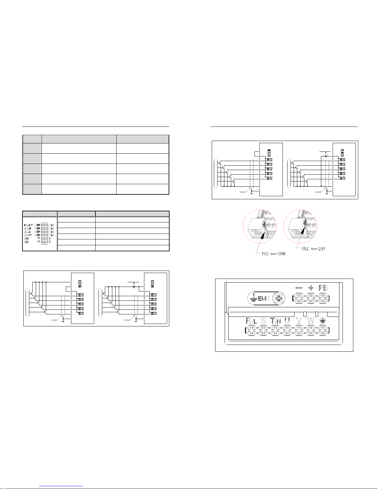
● Function Specification of Switch Terminals
Switch Terminal Selecting Position Function Specification
RS485 Terminal Resistor RS485 Communication :connect with 120Ω terminal
A
O Output- frequency
A
O2: 0.0~100kHz frequency output
A
O Output- Current
A
O2: 0~20mA current output or 4~20mA current output
A
O Output- Volt age 0~10V voltage output
A
I1 Input- Current/Voltage AI1: Input 0~20mA or 0~10V
A
I2 Input- Current/Voltage AI2: Input 0~20mA or 0~10V
● Multi-function input point connection
PNP transistor connection mode:
-
+
External power supply
E
X5
X3
X4
X2
X1
PLC
+24V
Enabled external 24V power supply
COMCOM
Enabled inner 24V power supply
+24V
PLC
X1
X2
X4
X3
X5
Shield Cable
E
External control signals
+24V
PLC
COM
+24V
PLC
COM
VFD VFD
External control signals
Shield Cable
AC300 Series Vector Control Inverter Manual Installation and Wiring
21
NPN transistor connection mode:
Enabled inner 24V power sup ply
+24V
PLC
X1
X2
X4
X3
X5
COM
Shield Cable
E
(Default short connected )
E
COM
X5
X3
X4
X2
X1
PLC
+24V
Enabled external 24V power supply
External control signals
Shield Cable
Note:
Jumper between"+24V"and"PLC" need be removed
when external 24V power supply was chosen.
External 24V power supply
+
-
+24V
PLC
COM
+24V
PLC
COM
VFD VFD
External control signals
Jumper cap "+24V", "PLC", "COM" connection diagram:
Main circuit wiring
● Main circuit wiring
Terminals array and definition:
AC300 Series Vector Control Inverter Manual Installation and Wiring
22
Table 3-3: Main circuit terminal arrangement and definition of AC300 series inverter
Ter min al Name Definition
(-)
DC power terminal
DC power output, (-) means DC bus cathode, (+) means
DC bus anode, used for external braking unit.
(+)
(+)
Braking resistance terminal Used for external braking resistance to realize quick stop.
PB
P1
DC reactor terminal Used for external DC reactor.
(+)
R
Inverter input terminal Used to connect 3-phase AC power supply. S
T
U
Inverter output terminal Used to connect the motor. V
W
Earth Earth terminal, earth resistance<10 OHM
E
● 3-phase 380V machine main circuit wiring
Table 3-4: Suggested cable diameter and fixed moment 3-phase 380V machine main circuit
Model
Main circuit terminals
screw specifications
Suggested fixed
moment (N·m)
Suggested Copper-core
cable specification mm
2
AC300-T3-R75G M4 1.2~1.5 1.5mm2(14)
AC300-T3-1R5G M4 1.2~1.5 2.5mm2(12)
AC300-T3-2R2G M4 1.2~1.5 2.5mm2(12)
AC300-T3-004G M4 1.2~1.5 4mm2(10)
AC300-T3-5R5G M4 1.2~1.5 6mm2(9)
AC300-T3-7R5G M5 2~2.5 6mm2(9)
AC300-T3-011G M5 2~2.5 10mm2(7)
AC300-T3-015G M6 4~6 10mm2(7)
AC300-T3-018G M6 4~6 16mm2(5)
AC300-T3-022G M6 4~6 16mm2(5)
AC300-T3-030G M8 8~10 25mm2(3)
AC300-T3-037G M8 8~10 25mm2(3)
AC300-T3-045G M8 8~10 35mm2(2)
AC300-T3-055G M10 11~13 35mm2(2)
AC300 Series Vector Control Inverter Manual Installation and Wiring
23
AC300-T3-075G M10 11~13 50mm2(1)
AC300-T3-090G M10 11~13 50mm2(1/0)
AC300-T3-110G M10 11~13 70mm2(2/0)
AC300-T3-132G M10 11~13 95mm2(3/0)
AC300-T3-160G M12 14~16 95mm2(4/0)
AC300-T3-185G M12 14~16 120mm2
AC300-T3-200G M12 14~16 150mm2
AC300-T3-220G M12 14~16 150mm2
AC300-T3-250G M12 14~16 185mm2
AC300-T3-280G M12 14~16 185mm2
AC300-T3-315G M16 20~23 240mm2
AC300-T3-355G M16 20~23 240mm2
AC300-T3-400G M16 20~23 300mm2
AC300-T3-450G M16 20~23 400mm2
AC300-T3-500G M16 20~23 400mm2
AC300-T3-560G M16 20~23 500mm2
Note:
Here we suggest using copper joins as mains electric connectors of machine over 185KW. Please
refer the cut section area above.
● Single-phase 220V machine main circuit wiring
Table 3-5: Suggested cable diameter and fixed moment single-phase 220V machine main circuit
Model
Main circuit terminals
screw specifications
Suggested fixed
moment (N·m)
Suggested Copper-core cable
specification mm2 (AWG)
AC300-S2-R40G M4 1.2~1.5 1.5mm2(14)
AC300-S2-R75G M4 1.2~1.5 2.5mm2(12)
AC300-S2-1R5G M4 1.2~1.5 2.5mm2(12)
AC300-S2-2R2G M4 1.2~1.5 4mm2(10)
● Suggested main circuit components specification
Table 3-6: Suggested mains fittings for 3-phase 380V machine
Model
Contactor
specification
Breaker
specification
DC reactor Input filter Output filter
AC300-T3-R75G 10A 10A ------ NFI-005 NFO-010
AC300-T3-1R5G 10A 10A ------ NFI-005 NFO-010
AC300-T3-2R2G 16A 15A ------ NFI-010 NFO-010
AC300-T3-004G 16A 20A ------ NFI-010 NFO-010
AC300 Series Vector Control Inverter Manual Installation and Wiring
24
AC300-T3-5R5G 25A 20A ------ NFI-020 NFO-020
AC300-T3-7R5G 25A 30A ------ NFI-020 NFO-020
AC300-T3-011G 32A 40A ------ NFI-036 NFO-036
AC300-T3-015G 40A 50A ------ NFI-036 NFO-036
AC300-T3-018G 50A 60A ------ NFI-050 NFO-050
AC300-T3-022G 50A 75A ------ NFI-050 NFO-050
AC300-T3-030G 63A 100A DCL-80 NFI-080 NFO-080
AC300-T3-037G 80A 125A DCL-100 NFI-100 NFO-100
AC300-T3-045G 100A 150A DCL-110 NFI-100 NFO-100
AC300-T3-055G 125A 175A DCL-125 NFI-150 NFO-150
AC300-T3-075G 160A 200A DCL-150 NFI-150 NFO-150
AC300-T3-090G 220A 250A DCL-200 NFI-200 NFO-300
AC300-T3-110G 220A 300A DCL-200 NFI-200 NFO-300
AC300-T3-132G 250A 400A DCL-300 NFI-300 NFO-300
AC300-T3-160G 300A 500A DCL-300 NFI-300 NFO-300
AC300-T3-185G 400A 600A DCL-400 NFI-400 NFO-400
AC300-T3-200G 400A 700A DCL-400 NFI-400 NFO-400
AC300-T3-220G 630A 800A DCL-500 NFI-600 NFO-600
AC300-T3-250G 630A 1000A DCL-600 NFI-600 NFO-600
AC300-T3-280G 630A 1200A DCL-600 NFI-600 NFO-600
AC300-T3-315G 630A 1200A DCL-800 ------ ------
AC300-T3-355G 800A 1400A DCL-800 ------ ------
AC300-T3-400G 1000A 1600A DCL-1000 ------ ------
AC300-T3-450G 1000A 2000A DCL-1000 ------ ------
AC300-T3-500G 1000A 2000A DCL-1200 ------ ------
AC300-T3-560G ------ 2000A DCL-1200 ------ ------
Note: For DC reactor, input filter, output filter and other components specification details and circuit mode, please
refer chapter 7 “peripheral equipments and options”
AC300 Series Vector Control Inverter Manual Installation and Wiring
25
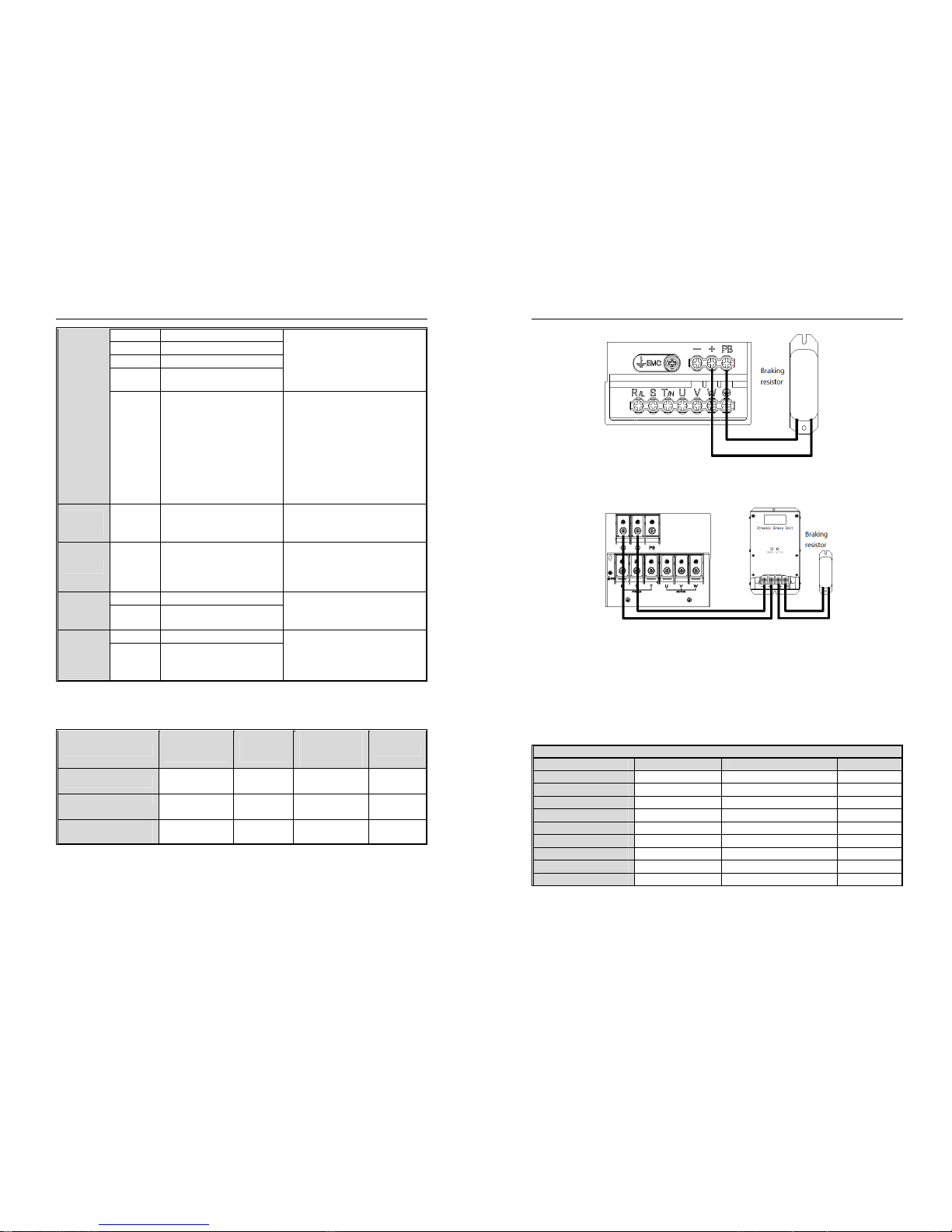
Control loop terminals
● Control loop terminals array
Table 3-7:AC300 series inverter control loop terminals array and definition
Sort Term in al Name Function definition
Power
supply
+10V-GND External +10V power supply
Provide +10V power supply to the outside,
the maximum output current: 50 mA is
generally used as external potentiometer
working power supply, potentiometer
resistance range: 1KΩ ~ 5KΩ
+24V-COM External +24V power supply
Provides +24V power supply to the
outside, generally used as digital input
and output terminal working power supply
and external sensor power supply
Maximum output current: 100 mA
PLC
External
common terminal
Factory default connection with +24V
When using X1~X5/PUL to drive the
external signal, the PLC needs to be
connected to the external power supply
and disconnected from the +24V power
supply (see "+24V", "PLC", "COM"
connection diagram for details)
Analog input
AI1-GND Voltage or current type analog input
1. Input current range: DC 0V ~ 10V / 0mA
~ 20mA
2. Voltage type input impedance: 100KΩ
3. Current input impedance: 500Ω
AI2-GND Voltage or current type analog input
1. Input current range: DC 0V ~ 10V / 0mA
~ 20mA
2. Voltage type input impedance: 100KΩ
3. Current input impedance: 500Ω
Digital input X1-PLC Multi-function contact input 1 Optocoupler isolation, compatible with
AC300 Series Vector Control Inverter Manual Installation and Wiring
26
X2-PLC Multi-function contact input 2 bipolar inputs.
1. Input impedance: 4.4 KΩ
2. High-level input voltage range: 10 ~
30V
3. Low-level input voltage range: 0 ~ 8V
X3-PLC Multi-function contact input 3
X4-PLC Multi-function contact input 4
X5-PLC
Multi-function contact input 5
X5/PUL-PLC Multi-function contact input 5 / high
speed pulse input
In addition to the features of X1 ~ X4, X5
can also be used as a high-speed pulse
input channel
(separate model).
1. Optocoupler isolation, compatible with
bipolar input, maximum input frequency:
100KHZ
2. Input impedance: 1.5KΩ
3. Pulse input level range: 10 ~ 30V
Analog
output
AO1-GND Analog output 1
1. Output voltage range: DC 0V ~ 10V
2. Output current range: DC 0mA ~ 20mA
3. Pulse output range: 0 ~ 50kHz
Digital output Y-C OM Digital output 1
Optocoupler isolation, open collector
output
1. Output voltage range: DC 0V ~ 30V
2. Output current range: DC 0mA ~ 50mA
Relay output
TA-T C Normally open terminal Contact drive capability:
240VAC, 3A
30VDC, 5A
TB-TC Normally closed terminal
communicati
on
Terminal
A+ Communication terminal A+ RS485 communication interface.
Select the RS485 communication access
120ohm terminal resistance by the toggle
switch S4 (see Table 3-5 for details)
B- Communication terminal B-
● Control loop terminal wiring specification
Table 3-8: Control loop terminal wiring specification
Ter min al
Bolt specification
(mm)
Fixed moment
(N·m)
Cable
specification
(mm2)
Cable type
A+ B- M2.5 0.4~0.6 0.75
Twisted-pair
shielded cable
+10V GND A0 AI1 AI2
M2.5 0.4~0.6 0.75
Twisted-pair
shielded cable
+24V COM Y TA TB TC PLC
X1 X2 X3 X4 X5/PUL
M2.5 0.4~0.6 0.75 Shielded cable
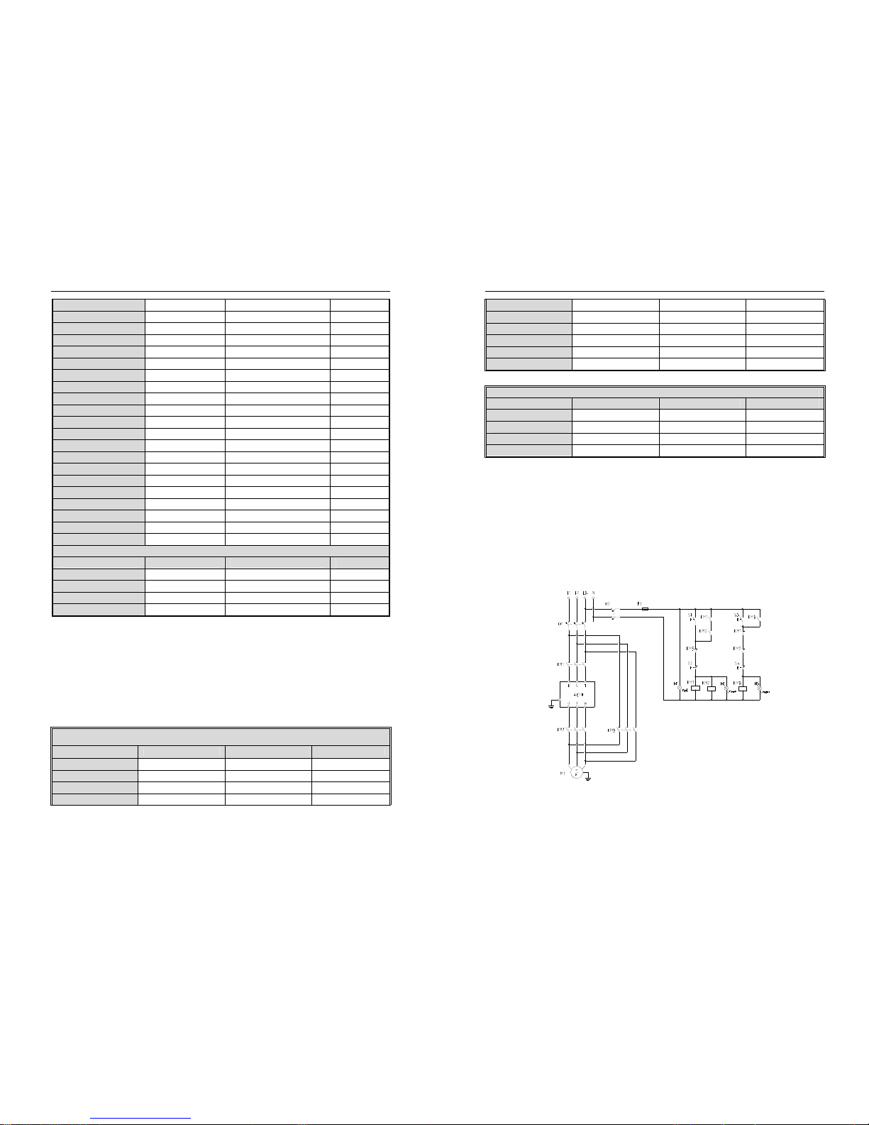
Braking unit (braking resistance) connection
● Brake resistance wiring of machine with 22KW or less power:
AC300 Series Vector Control Inverter Manual Installation and Wiring
27
Fig 3-9: AC300 series frequency inverter brake resistance wiring of machine with 22KW or less power
● Brake resistance wiring of machine with 30KW or above
Fig 3-10: AC300 Series Frequency Inverter Brake resistance wiring of machine with 30KW or above
● Suggested braking resistance specification parameters
Braking resistance value and power in the chart are decided according to common inertia load and intermittent
braking mode. While used in large inertia occasion or long time frequent brake occasion, please adjust resistance value
and power according to the inverter specification and the rated parameter of braking unit. If any problem, please consult
customer service department of Veichi Electric Com., Ltd.
Table 3-9: Suggested braking resistance specification parameters of AC300 series inverter
Three-phase 380V
Motor power(kW) Resistance value(Ω) Resistance power(W)
Braking torque
0.75 kW 750Ω 150W 100%
1.5 kW 400Ω 300W 100%
2.2 kW 250Ω 400W 100%
4.0 kW 150Ω 500W 100%
5.5 Kw 100Ω 600W 100%
7.5 kW 75Ω 780W 100%
11 k W 5 0Ω 1,200W 100%
15 kW 40Ω 1,500W 100%
18.5 kW 32Ω 2,000W 100%
AC300 Series Vector Control Inverter Manual Installation and Wiring
28
22 kW 32Ω 2,000W 100%
30 kW 24Ω 3,000W 100%
37 kW 20Ω 3,700W 100%
45 kW 16Ω 4,500W 100%
55 kW 13Ω 5,500W 100%
75 kW 9Ω 7,500W 100%
90 kW 6.8Ω 9,300W 100%
110 kW 6.2Ω 11,000W 100%
132 kW 4.7Ω 13,000W 100%
160 kW 3.9Ω 15,000W 100%
185 kW 3.3Ω 17,000W 100%
200 kW 3Ω 18,500W 100%
220 kW 2.7Ω 20,000W 100%
250 kW 2.4Ω 22,500W 100%
280 kW 2Ω 25,500W 100%
315 kW 1.8Ω 30,000W 100%
355 kW 1.5Ω 33,000W 100%
400 kW 1.2Ω 42,000W 100%
450 kW 1.2Ω 42,000W 100%
500 kW 1Ω 42,000W 100%
560 kW 1Ω 50,000W 100%
Single-phase 220V
Motor power(kW) Resistance value(Ω) Resistance power(W)
Braking moment
0.4 kW 400Ω 100W 100%
0.75 kW 200Ω 120W 100%
1.5 kW 100Ω 300W 100%
2.2 kW 75Ω 300W 100%
● Build-in braking unit max braking performance
Braking unit of AC300 series product with low power can be selected according to the suggested braking
resistance specification parameters in table 3-11. In large inertia or long time frequent brake occasion, the
moment maybe should be increased. The max braking power is showed in the following table, the range of
which can not be over in use. Otherwise the equipment maybe destroyed. If any problem, please consult Veichi
Electric Com., Ltd customer service department.
Table 3-10:AC300 series inverter build-in braking unit max braking power
Three-phase380V
Inverter model Motor power Max braking current Min resistance
AC300-T3-R75G 0.75 kW 3.5A 200Ω
AC300-T3-1R5G 1.5 kW 3.5A 200Ω
AC300-T3-2R2G 2.2 kW 7A 100Ω
AC300-T3-004G 4 kW 10A 75Ω
AC300 Series Vector Control Inverter Manual Installation and Wiring
29
AC300-T3-5R5G 5.5 KW 10A 75Ω
AC300-T3-7R5G 7.5 kW 14A 50Ω
AC300-T3-011G 11 kW 17A 40Ω
AC300-T3-015G 15 kW 23A 30Ω
AC300-T3-018G 18.5 kW 28A 25Ω
AC300-T3-022G 22 kW 28A 25Ω
Three / Single-phase 220V
Inverter model Motor power Max braking current Min resistance
AC300-T/S2-R40G 0.4 kW 3.8A 100Ω
AC300-T/S2-R75G 0.75 kW 3.8A 100Ω
AC300-T/S2-1R5G 1.5 kW 6.5A 60Ω
AC300-T/S2-2R2G 2.2 kW 10.5A 40Ω
Standby control system
Frequency inverter is composed of semiconductor, passive electronic component and driving part. All of them have
useful time, which means these parts may happen characteristic change or out of use in normal working environment.
And it will cause product fault. To avoid production stop led by the fault, we suggest preparing standby control system
when using the inverter.
Chart 3-11 is a standby control system for manual switch to power supply driving motor at inverter fault. Standby
control systems such as power supply Y/Δ step-down start way driving motor, power supply self-coupling reduction
voltage start mode driving motor, power supply soft start mode driving motor or standby inverter system can be chose to
use according the actual requirement and environment.
Chart 3-11: Standby control system of power supply directly driving mode
AC300 Series Vector Control Inverter Manual Basic Operation and Trial Run
30
Chapter 4 Basic Operation and Trial Run
4.1 Safety Precautions
● No wiring while power supply is connected.Otherwise there is danger of electric shock.
● No operation while the cover is open.Otherwise, there is danger of electric shock.
● Please ensure reliable earth. Otherwise, there is danger of electric shock and fire.
● Before wiring please cut power supply of all related equipments and ensure main DC
voltage in safe range. And please do operation after 5 mins.
● Only professional trained person is allowed to operate this product.
● Please do not dismantle the inverter cover while it is electrified. Otherwise, there is
danger of electric shock.
● Please do not touch the printed circuit board of the inverter while it is electrified.
Otherwise, there is danger of electric shock.
● Please ensure reliable mains cable connection. If the mains cable is loose, thereis
danger of fire caused by joint overheat.
● Before electrifying, please check the power voltage again. Wrong power voltage can
cause fault or damage the inverter, even cause fire.
● Please do not install inverter on flammable material or attach flammable material to the
inverter. Before electrifying, please clear the surroundings.
Important
● While operation, please follow the ESD regulations. Otherwise, the inverter maybe
damaged.
● Please don’t cut the power directly while the inverter drives the motor running. The
power can’t be cut until the motor totally stop. Otherwise, the inverter maybe damaged.
● Please don’t cut or connect motor while the inverter drives the motor running. The motor
can’t be cut or connect until the inverter output is 0. Otherwise, the inverter maybe
damaged.
● Control cable should be twisted-pair shielded cable. The barrier should be connected to
the inverter earth terminal reliably to prevent the inverter from abnormal working.
● Unprofessional person can not operate, install, wiring, debug and maintain.
● Change, dismantle or maintain without permission may cause inverter damage. This
case is not in our quality assurance range.
AC300 Series Vector Control Inverter Manual Basic Operation and Trial Run
31
4.2 Keyboard layout and functions specification
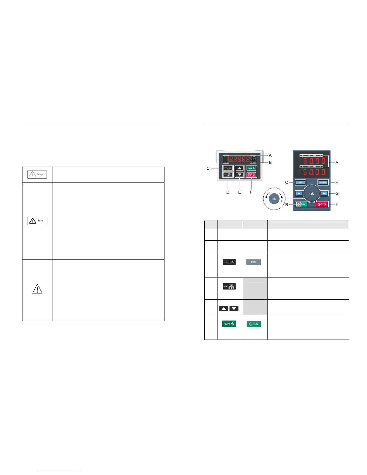
● Keyboard name
Integrated keyboard (37KW and below Double-line keyboard (37KW or more machine)
●Key function
Integrated
keyboard
Double-line
keyboard
Function
A
Unit indicator
Hz: Frequency A: Current V: Voltage V/A: Voltage or
current RPM: Speed %: Percentage
B
Status Indicator
On: Forward running status Blinking: Reverse running status Off:
Stop status
C
Menu
Menu
Enter the function menu interface during standby or running;
press this button to exit the modification when the parameter is
modified; press the button (1 second) during standby or running
to enter the status interface directly.
D
Set/Shift
Set function: After modifying the value, press this key to confirm
the modified value.
Shift function: long press this button (1 second) to move the
operation bit, long press is not loose, then cyclic shift
E
Up, Down
The up key increases the operation value and the down key
decreases the operation value.
F
Run
Run
When the run/stop is controlled by the keyboard, press this
button to turn the inverter forward. The status indicator is always
on during forward run, and the status indicator is flashing during
reverse run.

AC300 Series Vector Control Inverter Manual Basic Operation and Trial Run
32
Stop/Reset Stop/Reset
When the command given channel is keyboard control, press
this key to stop the inverter; the parameter [F04.08] can be used
to define whether other command channels are valid; the
inverter resets when pressing the key in fault status.
G
Digital potentiometer: clockwise to increase the operating value,
counterclockwise to decrease the operating value
Set key: After modifying the value, press this key to confirm the
modified value.
Left/Right Shift
Move left and right operation bits
H
Jog/Reverse
Select the function of the key by parameter [F04.07], 0: reverse
1: jog
● Number word comparison table
Table 4-1: Digital Text Comparison Table
AC300 Series Vector Control Inverter Manual Fault Diagnoses and Processing
33
Chapter 5 Fault Diagnoses and Processing
This chapter explains the display content and processing of the inverter fault, alarm and operation fault. It also simply
explains the bad situation caused by inverter or motor fault and how to solve it. For the adjustment guide in trial run,
please refer this chapter too.
5.1 Fault Types
Type Inverter action while fault happens
External fault
In certain application occasions, external related equipments fault signals are considered in
the inverter control system as usage of monitoring, protection or switch control. At this time,
if one multi function terminal is defied as “external fault”, the inverter stops output alarm
signal.
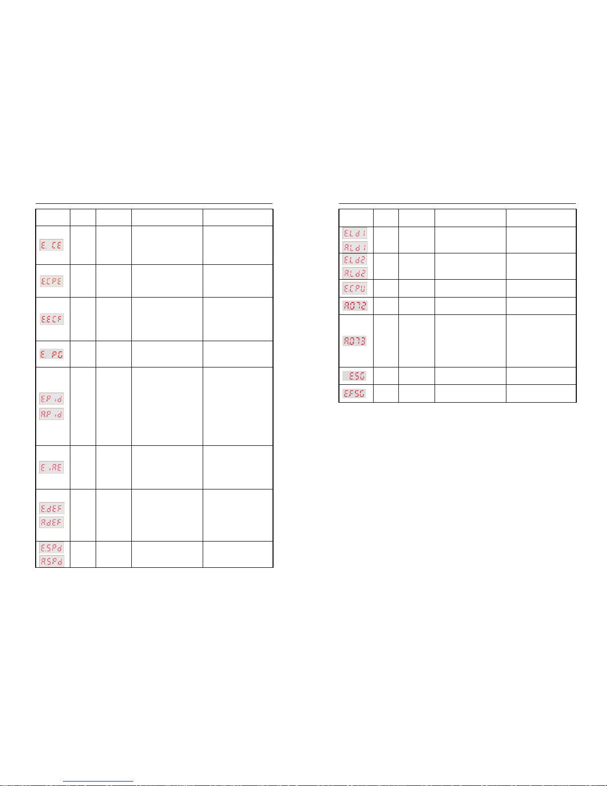
5.2 Fault Information and Details
Chart 5-1: Fault information and details
Keyboard
display
Commu
nication
code
Fault type Possible causes Treatment
64
Too low
voltage while
stop
● Power supply is too low
● Voltage detection circuit is
abnormal
● Check input power,clear
fault.
● Seek support from factory.
10
Too low
voltage in run
● Power supply is too low
● Power capacitance is too
small, or there is big impact
current in the power grid.
● Inner DC main contactor is
not connect well
● Check input power,clear
fault.
● Improve power supply.
● Seek support from factory.
7
Accel.
over-voltage
● Power voltage fluctuation
over limit.
● Start when motor is running .
● Detect power voltage and
clear fault.
● Restart motor until it
completely stop.Set E-30 as
1or2.

AC300 Series Vector Control Inverter Manual Fault Diagnoses and Processing
34
8
Decel.
over-voltage
● Deceleration time is too short.
● Load potential energy or
inertia is too large.
● Power voltage fluctuation
over limit.
● Prolong Deceleration time.
● Reduce load inertia or
improve inverter capacitance or
add braking unit.
● Detect power voltage and
clear fault.
9
Constant
speed
over-voltage
● Power voltage fluctuation
over limit.
● Detect power voltage and
clear fault.
● Install input reactor.
28
Over-voltage
while stop
● Power voltage fluctuation
over limit.
● Check input power,clear
fault.
● Seek support from factory.
4
Accel.
over-current
● Acceleration time is too short.
● Start running motor.
● V/F curve setting is not
suitable.Or torque boost too
high.
● Inverter capacitance is too
small.
● Prolong acc time.
● Restart motor until it totally
stop.Set E-30 as 1or2.
● Reset V/F curve or torque
boost value.
● Select inverter with right
capacitance.
5
Decel.
over-current
● Deceleration time is too short.
● Load potential energy or
inertia is too large.
● Power voltage fluctuation
over limit.
● Prolong Deceleration time.
● Connect external braking
resistance or braking unit.
● Select inverter with right
capacitance.
6
Constant
speed
over-current
● Sudden load change.
● Power grid voltage is too low.
● Check load change and clear
it.
● Check input power,clear
fault.
11
Motor
over-load
● V/F curve setting is not
suitable. Or torque boost too
high.
● Power grid voltage is too low.
● incorrect overload protection
setting.
● Locked-rotor run or too heavy
load.
● Universal motor long time low
speed run.
● Reset V/F curve or torque
boost value.
● Check input power,clear
fault.
● Unreasonable H-56 setting.
● Adjust load or select inverter
with right capacitance.
● If need long time low speed
run, please choose special
motor for inverter.
12
Inverter
over-load
● Load is too heavy.
● Acceleration time is too short.
● Start running motor.
● V/F curve setting is not
● Select inverter with right
capacitance.
● Prolong acceleration time
● Restart motor until it totally
AC300 Series Vector Control Inverter Manual Fault Diagnoses and Processing
35
suitable.Or torque boost too
high.
stop.Set E-30 as 1or2.
● Reset V/F curve or torque
boost value.
1/2/3
System
abnormality
● Acceleration time is too short.
● Short circuit between inverter
output phases or earth.
● Module is damaged.
● Electromagnetic disturb.
● Prolong acceleration time.
● Check periphery equipments
and restart after fault cleared.
● Seek support from factory.
● Check system wiring, earth,
shield and deal as required.
16
Inverter
over-heat
● Temperature is too high.
● Air channel is blocked.
● Fan connection parts is loose.
● Fan is damaged.
● Temperature detection circuit
fault
● Make the environment
meeting the requirement.
● Clear the air channel.
● Check and re-connect the
wire
● Change the same new fan.
● Seek support from factory.
17
Rectifier
bridge
over-heat
20
Motor
detection fault
● Detection overtime
● Perform static detection while
motor is running.
● Capacitance difference is too
big between motor and inverter.
● Motor parameter setting
mistake.
● Check motor connection
wire.
● Detect after motor stop
totally.
● Change inverter model.
● Reset parameter according
to nameplate.
21/69
Memory fault
● Electromagnetic disturb in
memory period.
● EEPROM damage.
● re-input and save.
● Seek support from factory.
30 Reserved ●Seek support from factory.
13
/65
Input phase
missing
● 3 input phase missing
● Check 3phase input power
and phase.
● Check 3phase input power
wiring.
14
Output phase
missing
● 3 phase output of inverter
missing connection with motor
● Check wire between inverter
and motor, earth and motor
insulation.
-
Output
Ground
● The output side of the inverter
is shorted to ground.
● Check wiring and motor
insulation.
19
Current
detection fault
● Detect circuit fault.
● Phase imbalance
● Seek for technique support.
● Check motor and wiring.
17
Inverter
external fault
● Peripheral equipment fault
protection.
●Check peripheral equipment.
E.PAn
Keyboard ● Keyboard wire fault. ● Check keyboard wire
AC300 Series Vector Control Inverter Manual Fault Diagnoses and Processing
36
connect fault ● Keyboard component
damage.
● Seek support from factory.
18
RS485
communicatio
n fault
● Baud rate not right.
● Communication connection
not right.
● Communication format not
right.
● Set right Baud rate
● Check communication wiring
● Check Communication
format
E.CPE
Parameter
copy fault
● Parameter copy
communication is fault.
● Copy keyboard is not match
the inverter.
● Check wire.
● Select the specified external
keyboard model.
-
Expansion
card
connection is
abnormal
● The expansion card
communicates with the inverter
for timeout;
● The expansion card does not
match the drive.
● Check the connector and
re-plug the cable;
● Use the expansion card of
the specified model.
27
PG card
connection is
abnormal
● PG card and inverter
connection failure
● Check connection
29
/66
PID feedback
fault
● PID feedback disconnection
alarm upper limit is set
improperly
● PID feedback disconnection
alarm lower limit is set
improperly
● Lose PID feedback wiring
● Feedback sensor failure
● Feedback input loop fault
● Confirm the sensor status
and replace the sensor if it is
damaged.
● Correct wiring
● Confirm the set values of
F11.27 and F11.28
31
Initial position
angle learning
failed
● Check motor parameters
● Check the motor parameters;
● Learn after the motor is
stationary;
● Seek technical support from
manufacturers.
32
/70
Speed
deviation is
too large
●Checkout time or check level
setting is unreasonable
● Motor parameter is abnormal
● Check the motor parameters
and re-learn again;
● Check the F10.24/F10.25
parameter settings;
● Seek technical support from
manufacturers.
33
/71
Speed
protection
● FA.27/FA.28 parameter
setting is abnormal
● Motor parameter is abnormal
● Check the motor parameters
and re-learn again;
● Check the F10.27/F10.28
AC300 Series Vector Control Inverter Manual Fault Diagnoses and Processing
37
● Check the F6 group vector
control parameters
parameter settings;
34
/67
Load
protection 1
● The checkout time or check
level setting is unreasonable
● Check the F10.18/F10.19
parameter settings;
35
/68
Load
protection 2
● The checkout time or check
level setting is unreasonable
● Check the F10.20/F10.21
parameter settings;
36
CPU
time out
● CPU timing timeout
● Seek technical support from
manufacturers.
72
GPS lock
machine
● GPS timing timeout
● Seek technical support from
manufacturers.
73
GPS
disconnection
● GPS communication
disconnection
● Whether the GPS expansion
card is connected properly;
● GPS communication card is
arrears;
● Seek technical support from
manufacturers.
40
Fan short
circuit
● Fan short circuit ● Check if the fan is smooth
39
Motor short to
ground
● Motor short circuit to ground
● Check if the motor is shorted
to ground
AC300 Series Vector Control Inverter Manual Fault Diagnoses and Processing
38
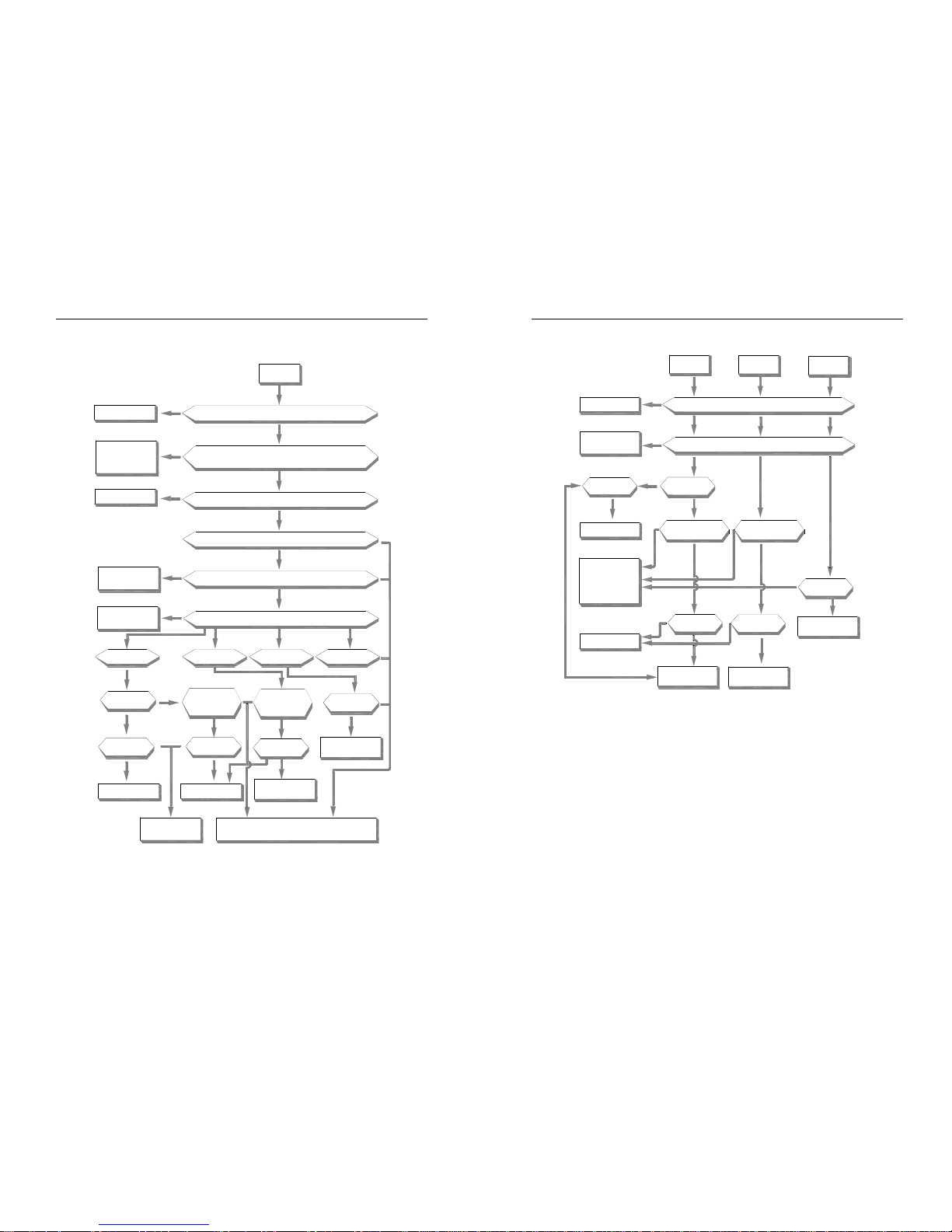
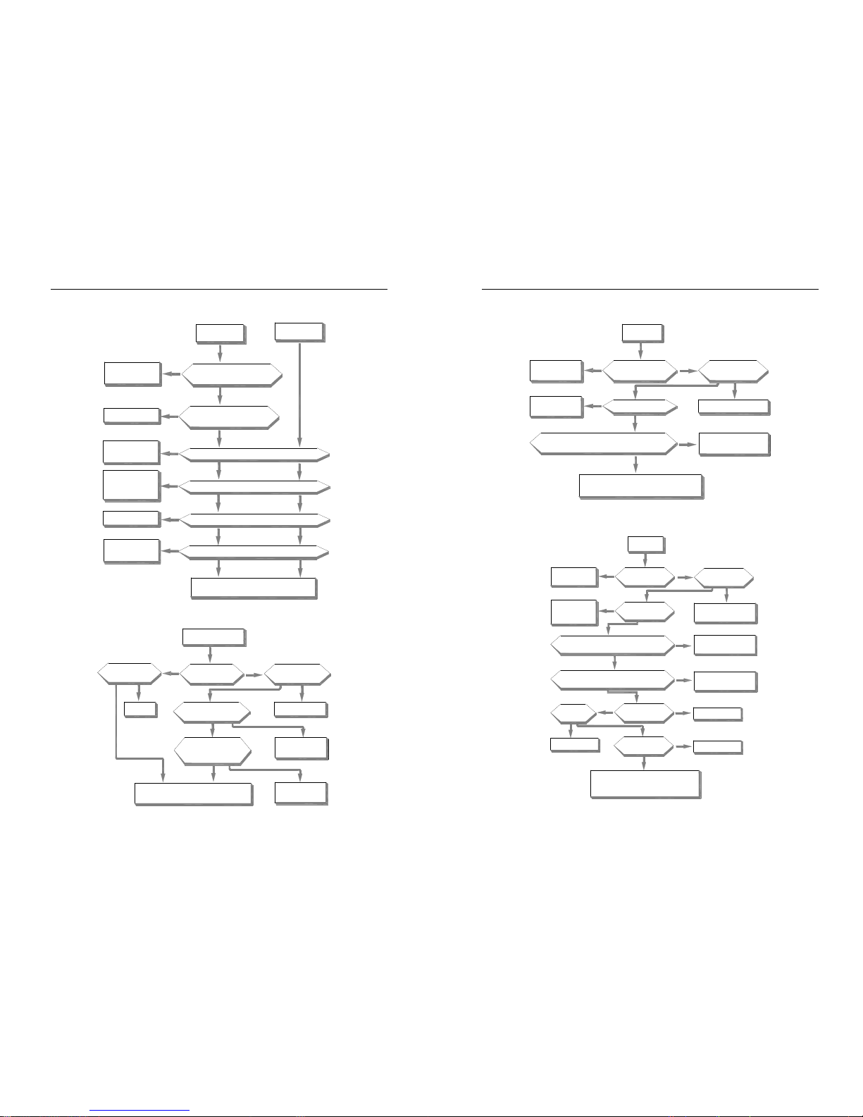
5.3 Fault Diagnoses Process
System fault diagnoses process
reduced or not
valuecan be
system fault
yes
yes
yes
yes
yes
yes
yes
yes
yes
yes
yes
yes
yes
yes
yes yes
yes
yes
no
no
no
no
no
no no
no
no
no
no
no
no
no
Clear short circuit
Whether there is short circuit between outo ut terminal U/V/W and the motor
Short the cable or
add outout reactor
Cable between output te rminal U/V/W and motor
is too long that leakage current cause inverter protection
Clear disturbance
Is there serious electroma gnetic disturbance?
While disconnect output wire and run,whether there is system fault alarm
Three phase outout voltage balance is ok or not?
Whether overload or not?
Connect load and
operate as follows
Reduce load or
enhance power
Display E.SC
while start
Display E.SC
while stop
Display E.SC while
constant speed
Display E.SC while
machine stop
Torque enhance value
is suitable or not
Whether acceleration
time is too short
Whether deceleration
time is too short
Whether load
change suddently
Torque enhance
ACC time can be
prolonged or not
Dec time can be
prolonged or not
Reduce load change
or enhance power
Reduce
Prolong setting time
Check braking mode,
seek tec support
Reduce load or
enhance power
Inverter fault or misaction caused by
noises.Pls find technic support
AC300 Series Vector Control Inverter Manual Fault Diagnoses and Processing
39
Over-current diagnoses process
Check braking mode
and seek for technic support
Reduce load change
or improve power
Reduce load change
or improve power
Whether set longer
decelerationtime
Set longer acceleration
time or not?
Prolong setting time
Whether load
changes suddently
May fault or misaction
caused by noise.Please
find technic support
Is deceleration
time set too short?
Is acceleration time
set too short?
Reduce the value
Whether torque
enhance value is too
Can be reduced?
Reduce load or
enhance power
Whether load is too large
Whether short circuit between output terminal
U/V/W and motor or earth circuit
Clear short circuit
no
no
no
no
no
no
no
no
no
no
no
no
yes
yes
yes
yes
yes
yes
yes
yes
yes
Constant speed
over curent E.0C3
Decelerate over
curent E.0C2
Accelerate over
curent E.0C1
AC300 Series Vector Control Inverter Manual Fault Diagnoses and Processing
40
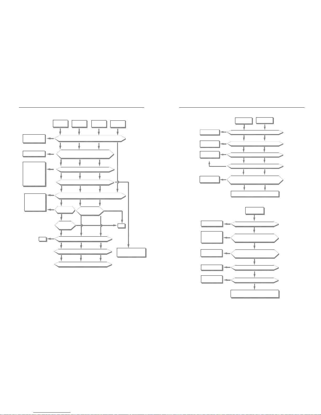
Over-voltage diagnoses process
ACC over
voltage(OU1)
DCC over
voltage(OU2)
Constant speed
over voltage(OU3)
Stop state over
voltage(OU4)
Fower votage in fixed range or not
no
no
no
no
no
no
no
no
no
no
no
no
no
no
no
no no
no
yes
yes
yes
yes
yes
yes
yes yes
yes
yes
yes
yes
yes
yes
yes
yes
Reduce power voltage
into fixed range
Clear short circuit
Phase or earth short cirsuit bwteen U/V/W and motor
Whether it stops while restart the motor
Whether act while load suddently changes to"0"
Whether DC circuit voltage of main loop is above protection value while act
Maybe inverter fault or
misact.Plese seek for
technic support
Whether act while
suddently stop ACC
Can prolong DCC time or not
prolong
ACC time can be
prolong or not
Load intertia can be reduced or not
Whether used braking unit or DC braking function
Please check braking unit and seek for technic support
Use braking unit or DC
braking function
Reduce
Stop motor and restart.
Or DC braking,then start
(E-30:1). Or speed track
start(E-30:2)
AC300 Series Vector Control Inverter Manual Fault Diagnoses and Processing
41
Low-voltage supply
yes
yes
yes
yes
yes
yes yes
no
no
no
no
no
no
no
no
Whether power off,including instant power off
Restart after reset
Change fault component
and correct bad contact
Is there any fault component or bad contact in power circuit
Whether power voltage is in fixed range as required
Is there any big load start or st op under the same power supply
votage between DC circuit P+ and N- in
main loop is over E-55 setting or not
Maybe inverter fault.please seek for tec hnic support
Modify power supply
system as required
Adjust E-55 setting
Voltage is too low
while stop Lu1
Voltage is too low
while running Lu2
Inner inverter over-heat
Whether cooling fan works normally
Whether temperature display(C-09)is
the same as the actual temperature
Whether load and carried frequency
E-20 setting are too high
Whether air cooling channels are air-logged
Whether the temperature is within the fixed range as required
Change fan
Maybe temperature ditection
circuit fault.please seek for
technic support
Reduce load and
carried frequency
Clear the air-logged channel
Adjust the temperature to
the fixed range as required
Maybe machine fault or misact.seek for technic support
no
no
no
no
no
yes
yes
yes
yes
yes
Inner inverter
overheat OH
AC300 Series Vector Control Inverter Manual Fault Diagnoses and Processing
42
Over-load
yesyes
yes
yes
no
no
no
no
no
no
no
yes
yes
yes
no
no
Change torque improving
or V/F curve setting
Prolong ACC/DCC time
Restart after motor stop or
change start mode E-30
to 1/2
Reduce load or
improve capacity
Correct setting value
Change externa
lthermal relay
Maybe inverter fault or misact.Please seek fo r technic support
Whether torque improving or V/F curve setting is suitable
Whether ACC/DCC time is too short
Whether the motor stops while restart
Whether load too high
Whether electric thermal relay overload
relay setting E-50 is suiable
Whether electric thermal relay overload
characteristic matches the motor overload
characteristic
Motor overload OL1
Inverter overload OL2
No display
Inverter keyboard
LED no display
Whether keyboard
connect line is reliable
Whether power indicater
linght on power board is
on or not
Whether circuit breaker
at power side is connect to
contacter
connect
connect
Whether power input
terminals R/S/T is normal
Whether there is short connect
or DC reactor between terminals
P1 and P+l
Maybe
inverter fault or motor heat
caused by noise.Please find technic support
Short connect or
connect DC reactor
yes
yes
yes
yes
yes
no
no
no
no
no
Find our the fault cause
and clear the fault
AC300 Series Vector Control Inverter Manual Fault Diagnoses and Processing
43
Motor heat
motor heat
Adjust torque imporoving
value and V/F characteristic
Whether torque improving and V/
F characteristic are suitable or not
Whether motor continuously
run at low speed
Reduce load or
improve capacity
Whether load is too large
Use special motor for inverter
Whether output terminals U/V/W output
voltage /current three phase balance well
no
no
no
no
yes
yes
yes
yes
Maybe motor fault
Maybe inverter fault or motor heat caused by
noise.Please find technic support
Motor does not rotate
no
no
no
no
no
no
yes
no
yes
yes
yes
yes
yes
yes
yes
yes
should be red uced.If there i s braking or brake uni,
please check whet her it is loose
Maybe motor i s locked because of too large load.Load
value is suitable
Whether torque improvin g
Improve torque
improving value
Motor fault
Whether
wiring is
correct or not
Whether load
is too large
Is there voltag e output on output terminal U/V/W
and three phase balance ok or not?
Correct connect
Maybe inverter fault .Please
find technic su pport
It works after co rrect the
upper frequency or given
frequency
It works after ch ecking the
cause and slving the problem
Have input frequ ency
signal or not
It works after c hecking
the cause and solving
the problem
Have input command
signal or not
Whether keyboard
displays fault information
Work after solving
fault and reset
Motor does
not work
Whether upper frequency limit E-10 or given frequency
is lower than the start frequency E-28 setting
AC300 Series Vector Control Inverter Manual Periodic Overhaul and Maintenance
44
Chapter 6 Periodic Overhaul and Maintenance
6.1 Safety Precautions
This chapter explains the safety rules in overhaul and maintenance.
● No operation under power connected state. Otherwise, there is danger of electric shock even
death.
● Before operation, please cut all related equipments power, ensure that the main circuit DC
current has droped to safe range. And please operate after 5 mins.
● No operation while cover/panel is dismantled. Otherwise there is danger of electric shock
even death.
● Do not dismantle the cover or PCB under power connected state. Otherwise there is danger
of electric shock death.
● Only professional person can maintain or change fittings. Otherwise, there is danger.
Do not wear loose clothes when install, debug, maintain. Related protective tools and
safeguard should be adopted.
● Tighten screw according to named torque. If main circuit wire connection is loose, there is
danger of overheat fire.
● Machine and motor earth must be reliable. Otherwise, there is danger of electric shock if
touch the cover.
● While operation, please follow the ESD regulations. Otherwise, the inverter maybe damaged.
● Do not change the circuit or structure of the inverter. Otherwise, the inverter maybe
damaged.
● Please confirm the rotate direction while no-load. Wrong direction can bring body injury or
huge wealth loss.
● Do not use damaged machine. Otherwise, there is danger of accident.
6.2 Overhaul
Frequency inverter is composed by semi-conductive components, passive electronic component and motive
component. All of these components have useful life. Even under normal working environment, some of the
components can not work after the life time. To avoid malfunction, daily checking, periodic overhaul, component
changing and other maintenance should be carried out to prevent. We suggest one overhaul every 3-4 months after
installation. The overhaul period should be shortened while under cases as below:
High temperature, high altitude;
Start and stop frequently;
AC power supply or load fluctuate badly;
With serious vibration or impact;
With dust, metal dust, salt, vitriol, chlorine;
AC300 Series Vector Control Inverter Manual Periodic Overhaul and Maintenance
45
Bad storage environment;
● Daily checking
To avoid machine damage and to prolong life time, please check the following items everyday.
Items Checking content Treatment
Power supply
Check if power supply meets the
requirement and whether there is
lack-phase.
Treat it as nameplate explains.
Surroundings
Check whether it meets the table3-1
requirement.
Make sure the problem and solve it.
Cooling system
Check whether the inverter or the motor
heat or change color abnormally and
cooling fan working state.
Check whether it overload. Tighten screw.
Check whether cooling fan is dirty or stall
rotate.
Motor
Check if there is abnormal vibration or
noise.
Tighten machine and electric connection
and lubricate the machine components.
Load
Check whether output current is over the
rated value of the motor or the inverter and
has lasted for a period.
Make sure whether it overload and
whether the machine model is right.
Cautions:
No operation under power connected state. Otherwise, there is danger of electric shock death. Before
operating, please cut all related equipments power, ensure that the main circuit DC current has dropped
to safe range. And please operate after 5 mins.
● Periodic overhaul
Under normal state, one overhaul every 3 or 4 months is ok. Please confirm the actual overhaul period according to
the machine use condition and work circumstance while using the machine.
Main circuit:
Items Checking content Treatment
Whole
● Check insulated resistance;
● Check circumstance.
● Tighten and change bad component;
● Clear and improve circumstance.
Electric connection
● Check whether the wire and connector
color changes, whether there is disrepair,
crack color change or aging in insulated
layer.
● Check whether the connect terminals
are frayed, damaged or loose.
● Earth checking.
● Change bad wire.
● Fasten terminals and change bad
terminals.
● Measure earth resistance and fasten
earth terminals.
Mechanical connection
● Check if there is abnormal vibration or
noise or something is loose.
● Tighten, lubricate and change the bad
components.

AC300 Series Vector Control Inverter Manual Periodic Overhaul and Maintenance
46
semi-conductive
component
● Check whether there is dust or rubbish.
● If there is obvious out change
● Clean operation environment
● Change damaged component
Electrolytic capacitor
● Whether there is liquid leak, color
change or crack. Whether the safety valve
outcrop, inflation, creak or liquid leak.
● Change damaged component
Peripheral equipment
● Peripheral equipment outlook and
insulation checking.
● Clear and change damaged component.
PCB
● Peculiar smell color change, bad
rust and connector checking.
● Fasten connector
● Clear PCB
● Change damaged PCB
Cooling system
● Check whether the fan is damaged
or blocked up.
● Whether rubbish and dust is stuck
to the heatsink .
● Is air inlet/outlet blocked? Or is
there something sticking to the
inlet/outlet.
● Clean operation environment
● Change damaged component
Keyboard
● Whether it is damaged. Check
whether display is complete.
● Change damaged component
Motor
● Check if there is abnormal vibration
or noise.
● Tighten machine and electric connection
and lubricate the machine components.
Cautions:
No operation under power connected state. Otherwise, there is danger of electric shock death. Before
operating, please cut all related equipments power, ensure that the main circuit DC current has dropped
to safe range. And please operate after 5 mins.
6.3 Maintenance
All equipments and components have useful life. Right maintenance can prolong the lifetime. But it can not avoid
damage. Please change the components before their lifetime over.
Component Useful lifetime
Fan 2~3year
Electrolytic capacitor 4~5 year
PCB 8~10 year
● Fan
While changing fan, please use original fan. You can contact Veichi company or the dealer. There are inverter
AC300 Series Vector Control Inverter Manual Periodic Overhaul and Maintenance
47
models with many fans in one machine. To prolong these machines’ lifetime, you had better to change all fans while
changing the cooling fan.
Cautions:
No operation under power connected state. Otherwise, there is danger of electric shock death. Before
operating, please cut all related equipments power, ensure that the main circuit DC current has dropped to safe
range. And please operate after 5 mins.
While the inverter is working, the heatsink temperature will be higher as the consumption. To prevent
from scald, please do not touch the heatsink and do not change the fan until the temperature being safe.
To ensure the best performance of the inverter, please use the original fan.
● Other components
The replacement of the other components has strict requirements on maintenance technic and product familiarity.
And they can not be used without strict detection after replacement. So we suggest the user not to replace the other
inner components. If they need to change indeed, please contact to the dealer or the sales department of Veichi electric
company.
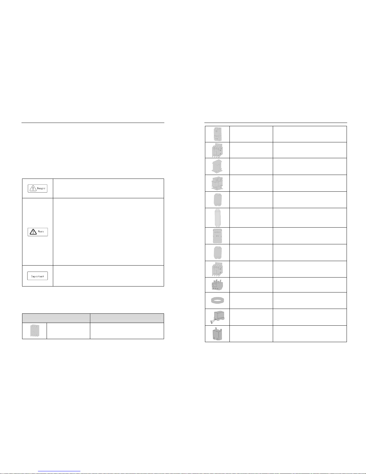
AC300 Series Vector Control Inverter Manual Peripheral Equipments and Options
48
Chapter 7 Peripheral Equipments and Options
7.1 Safety Precautions
User must obey to the following safety rules and related requirements while using the peripheral equipments and
selecting components.
● No operation under power connected state. Otherwise, there is danger of electric
shock.
● Before operation, please cut all related equipments power, ensure that the main circuit
DC current has dropped to safe range. And please operate after 5 mins.
● No operation while cover/panel is dismantled. Otherwise, there is danger of electric
shock.
● Do not dismantle the cover or PCB under power connected state. Otherwise, there is
danger of electric shock.
● Only professional person can install, debug or maintain the peripheral equipments and
options. Otherwise, there is danger.
● Do not ware loose clothes when install, debug, maintain. Rated protective tools and
safeguard should be adopted.
● Do not change wire, dismantle jumping wire, optional card, or change cooling fan while
the inverter is running. Otherwise, there is danger of electric shock.
● Tighten screw according to named torque. If main circuit wire connection is loose, there
is danger of overheat fire.
● Earth of the peripheral equipments and options must be reliable to prevent human body
injury.
● While operation, please follow the ESD regulations. Otherwise, the inverter maybe
damaged.
● Do not cut the power supply while the inverter is outputting voltage. Otherwise, the
inverter maybe damaged.
7.2 Peripheral Equipments
Normal peripheral equipments are showed as follows. To order the peripheral equipments, please consult our dealer
or sales department.
Peripheral equipment Functions
Breaker
Protect power system and prevent malfunction impact
other equipments working when short-circuit happens. And
over-load protection.
AC300 Series Vector Control Inverter Manual Peripheral Equipments and Options
49
Leakage current breaker
Earth protection prevent electric shock(suggest to use the
type which can prevent high-frequency leakage current)
Electromagnetic contactor
Separate power and inverter indeed and realize basic
relay control.
AC input reactor
Improve power side factor and isolate the noise
disturbance to the frequency inverter from the power side.
DC reactor Restrain ultra harmonics and improve power factor.
Input side noise filter
Reduce frequency inverter disturbance to the power and
reduce the power grid disturbance.
Braking resistor Passive energy consume unit of electric braking.
Consumption braking unit
Electric braking control unit, controlling the braking
resistance consume the regenerated electric power of the
motor efficiently.
Output side noise filter Reduce the output side wire electromagnetic disturbance.
Standby system Standby system for inverter malfunction.
Heat relay Protect the motor while over load.
0-phase reactor
Reduce electromagnetic disturbance of the frequency
inverter (suitable for input/output side).
Main loop surge absorption unit
Restrain surge voltage while main loop switch components
act.
Winding surge absorption unit Restrain surge voltage when the AC contactor acts.
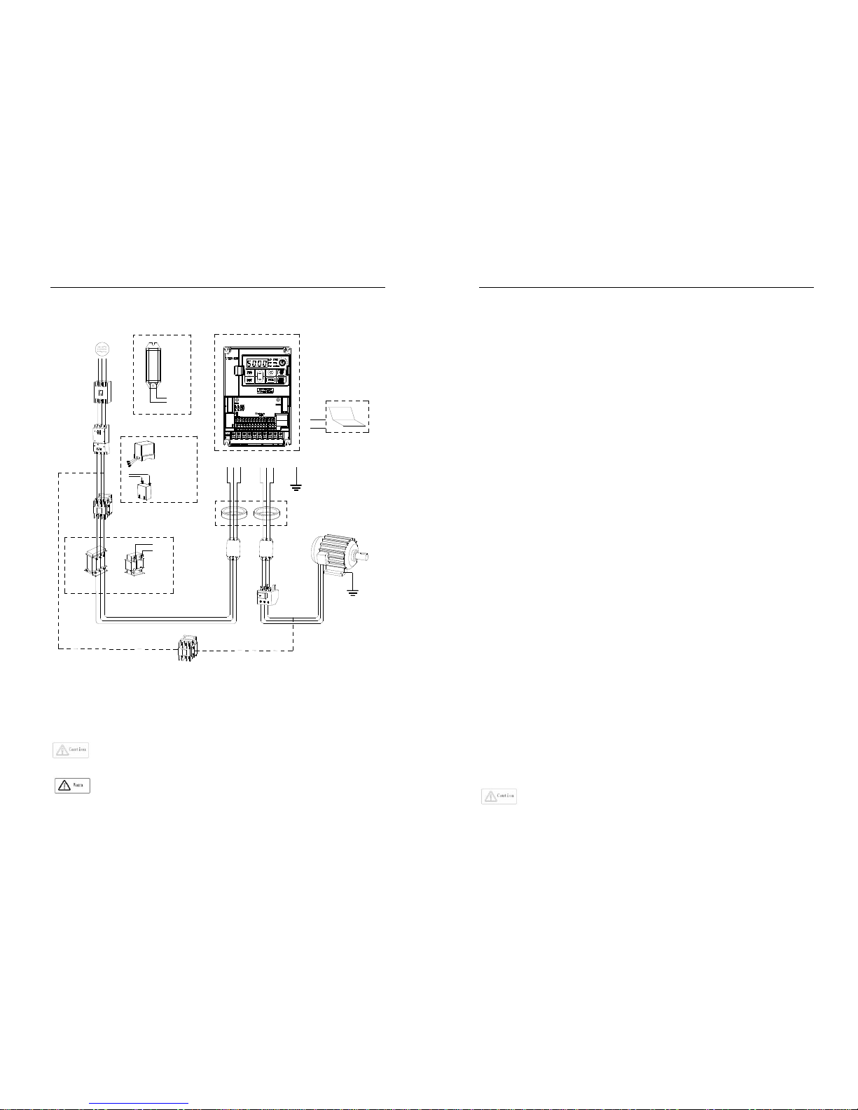
AC300 Series Vector Control Inverter Manual Peripheral Equipments and Options
50
7.3 The use of peripheral equipments
N(-)
P(+)PBR
S
T
UV
W
E
Inverter
Motor
Earthing
Zero-phase rector
Output side
noise filter
Input side noise
filter
DC rector
Contactor
Main loop surge
absorbale unit
Leakge current
breaker
A+
B-
Control sysytem standby
support PC
tool(software)
R
E
S
T
U
V
W
(+)
P1
AC rector
power
Breaker
PB
P(+)
Braking resistance
Braking unit
Winding surge
absorbable unit
Surge restrainer
①
②
③
④
⑤
⑥
⑦
⑧
⑨
⑩
Rector
Earthing
Heat relay
VECHI
www.veichi.com
Chart 7-1: Peripheral equipments connetion
Note:
Wiring breaker
To ensure wiring safe, protect power system and prevent malfunction impact other equipment
working when short-circuit happens, and protect while over-load, please do use wiring breaker between power supply
and main loop power input terminals R,S,T.
While choosing the breaker, the capacitance should be about 1.5-2 times of the rated output current of
the frequency inverter. Please compare the time characteristic of breaker and the characteristic of the
inverter protection (150% of the rated output current, one minute). Make sure there will be no skip.
Before main loop wiring, make sure to cut the breaker and electromagnetic contactor.
Otherwise, there is danger of electric shock.
AC300 Series Vector Control Inverter Manual Peripheral Equipments and Options
51
Leakage current breaker
The frequency inverter outputs peak voltage high-speed switch square wave, so there is high frequency leakage
current. For earth protection to prevent electric shock and leakage current fire, please install leakage current breaker.
Usually, one frequency inverter will bring 100mA leakage current (while the power cable length is 1m). If the length
prolongs 1m, there will be 5mA more leakage current. So please use leakage current breaker special for high frequency
leakage at the power input side of the frequency inverter. The factors which impact leakage current are as follows:
Capacitance of inverter;
Carrier frequency;
Motor cable type and wire length;
EMI/RFI filter.
To protect human body and inverter, please choose leakage current breaker which can use AC/DC power and can
reply high frequency leakage current. There should be one leakage current breaker with more than 200mA sensitive
current for every frequency inverter. If the frequency inverter outputs different wave, the high frequency leakage current
will be higher, what will make the breaker malfunction. At this case, please take following treatments:
Improve the sensitive current of the leakage current breaker;
Reduce the carrier frequency of the inverter.
Electromagnetic contactor
Electromagnetic contactor is a peripheral equipment what is set to separate power and inverter connection. While
inverter protective function is acting or carrying out emergency stop operation, the main loop power can be cut by
peripheral equipment. Please do not connect the electromagnetic switch or electromagnetic contactor to output circuit.
Otherwise, the inverter maybe damaged. While the power recovers after instant stop, if it needs to prevent the inverter
to auto-restart, please install electromagnetic contactor for control at the input side.
AC input reactor and DC reactor
To restrain current sharp change and high hypo harmonic current, it needs to use AC input reactor and DC reactor. It
can also improve power factor at the input side. In the following cases, AC input reactor or DC reactor must be used
(use both will bring better effect).
Need to restrain ultra harmonics current and improve power side factor;
Need to switch input phase capacitance;
When frequency inverter is connected to large capacitance power transformer (600kVA above);
Silicon-controlled converters such as DC motor driver are connected to the same power system.
If user has higher requirement on other harmonic restraint, please connect the external DC reactor .Before
connecting the external DC reactor, make sure to dismantle the short connector between the terminals P1 and (+).
Surge restrainer
Surge restrainer is divided to winding surge restrainer and main loop surge restrainer according to the use position.
Pls choose the right one which is suitable for the occasion. The aim of surge restrainer installation is restraining the
surge voltage brought by switch components such as inductive load which is surrounding the frequency inverter
(electromagnetic contactor, electromagnetic relay, electromagnetic valve, electromagnetic winding, electromagnetic
detent). Do not connect the surge restrainer to the output side of the frequency inverter. Otherwise, the frequency
inverter will be damaged.
Input side noise filter
Rectifier bridge of the inverter is uncontrolled rectifier. And input current is discontinuous impulse current. So the
harmonic current noise signal, what flows to power wire from the inverter inner, maybe bring bad impact on the
surrounding machines (radio, phone, noncontact switch, sensor). This time, we suggest to instal input side noise filter to
lighten the noise into the power wire. Besides, it can also reduce noise from the power wire into the frequency inverter.
Please use the special noise filter for the frequency inverter and the connection wire between the filter

AC300 Series Vector Control Inverter Manual Peripheral Equipments and Options
52
and the inverter should be as short as possible.
Output side noise filter
The frequency inverter outputs square wave with high-speed peak value voltage switch. So there is high-speed dv/dt
conver on the output cables that will produce a large number of radio disturbance and inductive signal. By installation
noise filter at the output side, the impact can be relieved. Please do not install the into phase capacitance and the noise
filter to the output circuit. Otherwise, there is danger of damage to the frequency inverter.
phase reactor
0-phase reactor is used for reducing the electromagnetic interference of the frequency inverter, which is suitable for
the input side and output side. It equals to a three-phase common mode inductance. In actual use, according to the
actual magnetic core size and cable specification, it is better to make sure 3-5 circles winding ratio to bring the best
performance.
Braking reactor or braking unit
Renewable electricity consumption unit, please see the sixth part of the chapter three “electric installation”.
Heat relay
Please install the heat relay at the output side of the frequency inverter. When the motor enters into overload state, it
will cut the power source to protect the motor. While using one frequency inverter to drive one motor, it is unnecessary
to install heat relay. The motor overload protection current [F10.16] of the frequency will work. While using one
frequency inverter to drive multiple motors or the motor is drove directly by the power grid, please install heat relay
between the inverter and the motor. While installing the heat relay, please design to cut the sequence control circuit of
the MC at the main loop iuput side by the connection spot of the relay or design to input the heat relay action into the
frequency inverter as the exterior malfunction. And please pay attention to the following tips to avoid heat relay
malfunction and motor overheating at low speed.
Run at low speed
One frequency inverter run multiple motors
Motor cable is very long
Detect malfunction mistakenly for carrier frequency is too higher.
Low speed and heat relay
In normal case, the heat relay is suitable for the universal motor. While using the frequency inverter to run the
universal motor (standard motor), the motor current is 5-10% higher, comparing with the commercial power supply.
Besides, at low speed, even in the motor rated current range, the cooling capability of the fan drove by the motor axis
will reduce, which will bring motor overheat. So please set the motor overheat protection current [F10.16] in the
frequency inverter to be valid.
Motor cable is longer
While the motor cable is longer and the carrier frequency is higher, impacted by the leakage current, the heat relay
maybe malfunction. To avoid it, please reduce the carrier frequency or set higher detection value of the heat relay.
Before enhance the detection value, do confirm whether there is other cause for the motor overheat. Otherwise, there is
danger.
AC300 Series Vector Control Inverter Manual Function Parameter Specifications
53
Chapter 8 Function Parameter Specifications
8.1 Basic Parameters
F00.00 Motor control mode Setting range: 0~8 Defaul t: 0
Asynchronous motor control mode:(AM):
0: V/F control
When the frequency (F) is adjustable, the ratio of the control frequency to the voltage (V) is kept constant.
The control mode is used for speed control without requiring fast response and high precision.
3: High-performance VC without PG
There is without speed sensor vector control, which is used for speed control that requires high precision.
Under this mode control, the torque can respond fastly even without using the speed feedback signal of the motor, and
a large torque can be obtained when the low speed motor is running. For better control, please make motor parameter
auto-tuning.
4: High-performance VC with PG
There is vector control with speed sensor, which is used for speed control of fast torque response and high
performance torque control.
Mainly used for high-precision speed control, torque control, simple servo control and other places where strict control
performance is required. For better control, please make motor parameter auto-tuning. In order to receive the speed
feedback signal of the motor, you need to use the PG option card.
In order to receive the speed feedback signal of the motor, you need to use the PG optional card.
Synchronous motor control mode(PM):
6: High-performance VC without PG
The permanent magnet synchronous motor has no PG feedback vector control. Through the software algorithm, the
complete model and observer of the permanent magnet synchronous motor are built in, and the magnetic pole position
and speed of the motor are observed in real time.
The mode requires complete no-load identification of the motor, which is suitable for occasions where the
acceleration/deceleration time is high and the load is an impact load.
7: High-performance VC with PG
The permanent magnet synchronous motor has speed sensor control, featuring dynamic response and high control
performance. It can perform torque control and weak magnetic high-speed operation, and can be used for high-power
servo control.
1, 2, 5: Reserved
AC300 Series Vector Control Inverter Manual Function Parameter Specifications
54
Notes:
1. PG refers to the speed encoder, used as PG vector control, generally with photoelectric encoder or rotary
transformer, need to select the corresponding PG card according to PG type and parameters, see function
code [F05.30];
2. When selecting the vector control mode, before the first run, first input the motor parameters correctly
and perform automatic motor parameter tuning to obtain the correct motor parameters. For details, please
refer to the detailed description of the "F05" motor parameter group.
3. The parameters of the vector control parameter group should be correctly set to ensure good steady state
and dynamic control performance. For the parameter setting and adjustment of the vector control
parameter group, please refer to the detailed description of the "F06" parameter group.
4. When selecting the vector control mode, it should be noted that the inverter can only drive one motor at
the same time; and the inverter capacity and the motor capacity level cannot be too different, the inverter
can be two or smaller than the motor power level. Failure to do so may result in reduced control
performance or the drive system may not function properly.
F00.01 Reserved
F00.02 Run command channel
Setting range: 0~3
Default: 0
Uses for selecting inverter running, stop and running direction command input channel.
0: keypad control
Running and stop of inverter control by forward running key PRG , stop key STOP/RESET of operator keypad. When
[F04.07] parameter set to 1, REV/JOG is defined for JOG running.
1: terminal control
Running, stop and rotation direction of inverter control by terminal . See [F02.00~F02.09] for details. See [F02.23] for
the terminal operation control mode and [F02.24] for the terminal startup protection.
2: RS485 communications port control
The running command is given by the host computer through communication. For communication parameter settings,
please refer to the F13 communication control parameter group.
When the peer-to-peer broadcast communication, the slave selects the run command transmitted by the host as the
run command, please refer to [F13.09] for instructions.
When Modbus RS485 communication is valid, the running command is set and modified by address 0x3001/0x2001.
See Appendix 2: Modbus Communication Protocol for details.
When the Profibus-DP communication is valid, the running command is set and modified by the corresponding
address, see the Profibus-DP card instruction manual of the optional card.
3: Option card
The operation and stop of the inverter are controlled by the external optional card communication. For the installation
method and parameter setting of the optional card, please refer to the instruction manual of the same box with the
optional card.
Note:
1. STOP/RESET of keypad, reset command from control terminal or RS485 communication are all enabled
AC300 Series Vector Control Inverter Manual Function Parameter Specifications
55
when fault reset.
Tips:
2. The function of the STOP/RESET button of the keyboard can be selected. When external terminal control
or communication control, it can be defined as the function of stop button, please refer to parameter
[F04.08]; when using external terminal for running control, if using STOP of keyboard When the /RESET
key is stopped, the inverter will stop and block the external terminal running command. At this time, the
external terminal stop command must be input to unlock, and the external terminal running command is
valid again. The communication control is the same.
F00.03 Frequency given source channel A Setting range: 0~11 Default: 0
F00.04 Frequency given source channel B Setting range: 0~11 Default: 2
Select the given source of the inverter set frequency in [F00.03], [F00.04]; [F00.06] sets the relationship between
channel A and channel B.
0: Keyboard number given
The set frequency is given by the parameter [F00.08] keyboard digital setting frequency; the current setting value of
the parameter [F00.08] can be quickly modified by selecting the [F04.09] LED single digit selection keyboard up/down
keys; Value power-down storage and up/down key action limit selection can be found in parameter [F04.09].
1: Reserved
2: Voltage/Current analog AI1 given
3: Voltage/Current analog AI2 given
The set frequency is given and modified by the input analog quantity AI1, AI2. By linearizing the input analog quantity
value, the calibration 100% corresponds to the maximum frequency. For details, see “F03” parameter group analog
quantity processing.
4: Reserved
5: Terminal pulse PUL given
The set frequency is given and modified by the control terminal (PUL) input pulse signal; by linearizing the input
pulse signal, the calibration is 100% corresponding to the maximum frequency, see parameter [F02.27~F02.33] for
details.
6: RS485 communication given
The set frequency is given by the communication method. For the communication parameter setting, please refer to
the F13 communication control parameter group.
When the peer-to-peer broadcast communication, the slave selects the host to transmit the given frequency or output
frequency as the set frequency, please refer to [F13.09] for instructions. When Modbus RS485 communication is valid,
the set frequency can be set and modified by address 0x3000/0x2000. See Appendix 2: Modbus Communication
Protocol.
When the Profibus-DP communication is valid, the set frequency is set and modified by the corresponding address.
See the Profibus-DP card instruction manual of the optional card.
When the CAN-RS485 communication is valid, the set frequency is set and modified by the corresponding address.
See the instruction manual of the optional CAN-RS485 card.
 Loading...