

Veichi AC300-T3-R75G, AC300-T3-5R5P-B, AC300-T3-1R5P-B, AC300-T3-2R2G-B, AC300-T3-004G User Manual
...
2018

CONTENT
Chapter 1 Overview ............................................................................................................ ............................................. 1
1.1 Safety requirement and cautions ...................................................................................................................................................... 1
1.2 Before Use .......................................................................................................................................................................................... 1
1.3 T echnical criterion ............................................................................................................................................................................... 2
Chapter 2 Installation ...................................................................................................................................................... 4
Chapter 3 Keyboard layout and functions specification .......................................................................................... 8
Chapter 4 Function Parameter Table ........................................................................................................................... 9
4.1 Basic parameters ............................................................................................................................................................................... 9
4.2
Terminal of Input and Output Function Selection ..........................................................................................................................30
4.3 Monitor Code ....................................................................................................................................................................................31
4.4 Fault Code ........................................................................................................................................................................................33
Chapter 5 Periodic Overhaul and Maintenance ........................................................................................................ 34
5.1 Overhaul ............................................................................................................................................................................................34
5.2 Maintenance .....................................................................................................................................................................................35
Appendix: Modbus Communication Protocol .......................................................................................................... 36

1
Chapter 1 Overview
1.1 Safety requirement and cautions
Please do totally unders tand this par t before usin g the inverter.
Warning signs and meanings
This manual has used fo llowing s igns which me ans ther e is an importan t part of secu rity. While observing against the r ules, the re is a danger of
injury even death or machine system damage.
Danger: Wrong operation may cause death or large accident.
Caution: Wrong o peration may cause minor wound.
Operation requirement
Only professionally trained persons can be allowed to operate the equipment. “Profess ional trained persons “m eans the workers mus t have
experience professional trained sk ill, and mus t be fami liar with installatio n, wiring , running a nd mainta in and ca n rightly dea l wi th emergency cases
in use.
Safety guidance
Warning signs come for your s ecurity. They are measures to prev ent the opera tor and m achine system from damage. P lease care fully read this
manual before using and strict ly observe th e regula tions and w arning si gns while operating.
●Correct transpor tation, store, instal lation , careful operation and main tenance are imp ortant for inverter s afe operation. In transport and store
process, make sure the inverter is free from imp act and v ibration. It mus t be stored where is dry without corros ive air and conduc tive dust, and
the temperature must be lower than 60℃.
● This product carries d angerous vol tage and c ontrols dr iver machine with poten tial danger. If you don’t abide by the r egulations or requirements in
this manual, there is da nger of b ody in jury even death and mach ine syste m damage.
● Do not wire while th e power is connec ted. Otherwise , ther e is dan ger of dea th for e lectric sh ock. Before wiring, inspection an d mainte nance,
please cut off power s upply o f all rel ated equipm ent’s and ensure mai n DC vol tage in sa fe range . And p lease oper ate it after 5 mins.
● Power wire, mo tor wire a nd control wire shou ld be al l connecte d firmly. Earth must be reliable and ear th resistance mus t be lower than 10Ω.
● Human body e lectrostatic will damage inner sensi tive components seriously. Before operation, please fo llow ESD m easures. Otherwise, there is
danger of inverter damage.
● Inverter output vo ltage is p ulse wave . If components s uch as capac itor which improves p ower factor and press ure-sensitive res istance for
anti-thunder and so on a re installed at the output side , please disman tle them or change to input si de.
● No switch c omponents such as breaker and contactor at the output side ( If there must be one, pleas e make s ure the o utput cur rent is 0 whil e the
switch acting).
● No matter whe re the fault is , there is danger of serious accide nt. So there must be additional external preven t measures or oth er safety devices.
●Only used in applica tion fields as mak er stated. No use in equipmen ts related to spec ial fields s uch as emerge ncy, succor, ship, medical
treatment, aviation, nuclear and etc.
● Only Veichi Electric co., ltd service departmen t or its authorized service center can mai ntain the products. It may cause p roduct faul t while using
accessories not authorized or permi tted. Any defective components must be changed in time in main tenance.
1.2 Before Use
On receiving your order, please check the package and confirm in tact be fore opening, and check i f there’s any damag e, scratch o r dirt (damages
caused during transportation are n ot with in the company 's warrant y). If there’s any damage caused d uring tr ansportation, please contac t us or the
transport company immediately. After confirming the receip t of the goods intact, pleas e re-confirm if the produc t and your order are consisten t.
2
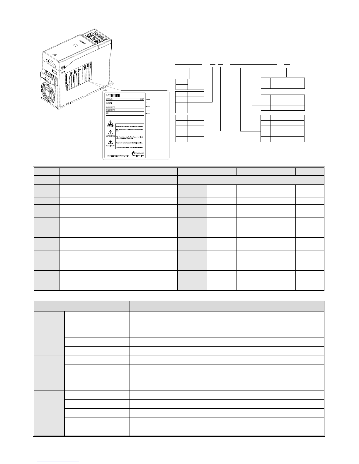
VFD Model
Input Model
Input Model1
Input Model2
Serial No.
Product
Series
AC300 - T 3 - 011 G /015P-B
Symbol
Voltage
2220V
3380V
6660V
T 3-Phase
S
Single
Phase
Code
VFD Type
G
General
Code
Adaptive motor (KW)
7R5
011
7.5
11
018
132
18.5
132
11
1140V
AC300
P
Blower & Pump
Symbol
Code
Accessories type
BBrake Unit
Phase
Symbol
Voltage 220V 380V 660V 1140V Voltage 220V 380V 660V 1140V
Power Rated Output Current (A) Power Rated Output Current (A)
0.75 4 3
110 380
210
121
75
1.5 7 4
132 420
250
150
86
2.2 10 6
160 550
310
175
105
4 16 10
185
600
340
198
115
5.5 20 13
200 660
380
218
132
7.5 30 17 10
220 720
415
235
144
11 42 25 1
5
250
470
270
162
15 5
5
32 1
8
280
510
330
175
18.5 70 38 22
315
600
345
208
22 80 45 2
8 355
670
380
220
30 110 60 3
5
400
750
430
260
37 130 75 4
5
25
450
810
466
270
45 160 90 52
31
500
860
540
325
55 200 110 6
3
38
560
990
600
365
75 260 150 8
6
52
630
1100
680
400
90 320 180 9
8
58
710
1260
760
450
1.3 T echnical criterion
Items Criterion
Power
input
Voltage ,frequency Three phase 380V 50/60Hz ,
Allowable fluctuations voltage unbalance rate:<3%; Frequency:±5%; aberration rate: as IEC6 1800-2 required
Inrush current Lower than rated current
Power factor ≥0.94(with DC reactor)
Efficiency ≥96%
Output
Output voltage Output under rated cond ition: 3 phase , 0~input voltage, inaccuracy<5%
Output frequency range G type:0~600Hz
Output frequency accuracy Max frequency ±0.5%
Overload capacity G type: 150% rated current/1 min, 180 % rated curren t/10s, 200% r ated curren t/0.5s
Main
Control
performance
Steady speed accuracy V/F without PG , VC without PG, V/F with PG , VC w ith PG
Starting torque Optimized SVPWM mode
Steady speed accuracy
0.7~16.0kHz
Starting torque VC without PG: rated load 1:100; VC with PG: r ated load 1:1000
Steady speed accuracy VC without PG: ≤2% rated synchron ized speed; VC with PG : ≤0.05% rated synchronized speed
3
Starting torque VC without PG: when 0.5Hz, 150% rated torque; VC with P G: when 0Hz, 200% rated torque
Torque response VC without PG: ≤20ms; VC w ith PG : ≤10ms
Frequency accuracy Digit setting: max fre quency×±0.01%; A nalog settin g: max freq uency×±0.2 %
Frequency resolution Digit setting: 0.01Hz; Analog se tting: max frequency×0 .05%
Basic
functions
DC braking capacity Starting frequency:0.00~50.00Hz; Braking time:0.0~60.0s; Braking current:0.0~150.0% rated current
Torque boost capacity Auto torque upgrade 0.0%~100.0%; Manual torque upgrade 0 .0%~30.0%
V/F curve
4 modes: one linearity torque char acteristic c urve ,one se lf-settin g V/F cur ve mode, one drop
torque characteristic curve (1.1 - 2.0 powe rs),and square V/F curve mode.
Acceleration/Deceleration
curve
2 modes: linear Acceleration/Dec eleration and S curve Acceleration/D ecelerat ion. 4 se ts of
ACC/DEC, time unit 0.01s selectable , longest time: 650 .00s.
Rated output voltage
Rely on power supply voltage compensate function, w hile motor ra ted voltag e is 100%, se t it at
the range of 50-100%(outp ut can no t over inpu t voltage).
Voltage auto-adj ustment While power supply voltage fluctuates, i t can auto-keep constan t output v oltage.
Auto energy-saving running
While under V/F control mode, accord ing to load situation, auto-op timize outpu t voltage to save
energy.
Auto-limit current Auto-limit the current whi le running to preven t over curren t break trouble.
Instant power off tre atment While instant power off, realize continual oper ation by b us voltage control.
Standard functions
PID control, speed track, power off res tart, jump fr equency, upper/lower frequency limit control ,
program operation, multi- speed , RS485, analo g output, freq uency impuls e output.
Frequency setting channels
Keyboard digital setting, Analog voltage/curren t termina l AI1, Analog voltage/current terminal AI2,
Communication given and multi-chann el termina l selection , Main and auxiliary chan nel
combination, expansion card, supporting differen t modes swi tch
Feedback input channel
Voltage /Current Terminal AI1, Voltage/Current Terminal AI12 , Communication given, Low-s peed
pulse input PUL, extension c ard
Running command channel Operation panel given, extern al termina l given, communica tion given , expansion card given
Input command signal
Start, stop, FWD/REV, JOG, multi-step speed, free stop, res et, ACC /DEC time se lection,
frequency given channel selec tion, exterior faul t alarm.
Exterior output signal
1 relay output, 1 collector ou tput, 1 AO output: 0~10V output or 4~20 mA output, or frequency
pulse output
Protection function
Overvoltage, under-voltage, current l imit, over-current, ove rload, electric thermal relay, overheat,
overvoltage stall, data protec tion, rapid spe ed protecti on, inp ut/output pha se failure protection
Keyboard
display
LED display
Single file 5 digital tube display Can monitor one state variable
Two file 5 digi tal tube display Can monitor two state variables
Parameter copy Can upload or download functi on code in formation o f inverter to realiz e fast param eter copy.
State monitor
Output frequency, given frequency , outpu t current, input vol tage, output v oltage, motor speed,
PID feedback, PID given value, module temperature etc. monitor parameters.
Fault alarm
,Over-voltage, under-voltage, over-current, s hort circui t, phase failure, overload, overhea t,
overvoltage stall, current limit, or da ta protection destroyed; Fault running state; Fault history.
Environme
nt
Install place
altitude ≤ 1000m,above 1000m down the rated amount, each increase of 100m down the r ated
amount of 1%;no condensation, ic e ,rain, snow, hail; solar radiation below 700W/㎡, air pressure
70-106 kPa
T emperature, humidity
-10~+50 , above 40 down the rated amount, t℃℃ he max temperature:60 (no load runni ng)℃
Vibration
9~200Hz,5.9m/s2(0.6g)
Store temperature -30—+60℃
Installation Hanging type, cabinet type
Protection degree IP20
Cooling mode Forced air cooling
4
Chapter 2 Installation
This section specifies the co nsiderations necessary for reliab le and sa fe operati on of the product by users.
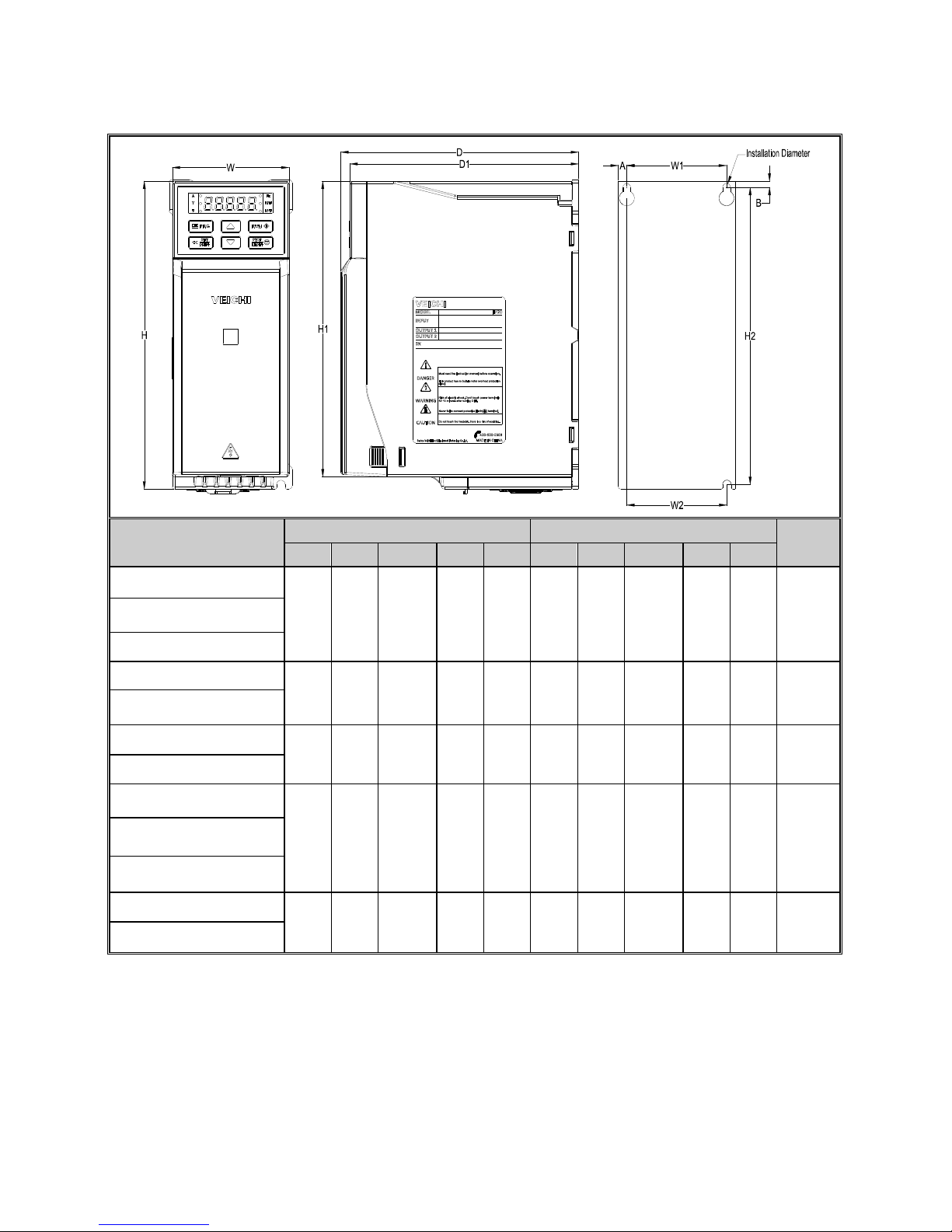
Overall Dimension of Inverter (Plastic)
MODEL
Overall Dimension(m m) Installation Dimension(mm)
Apertu
re
W H H1 D D1 W1 W2 H2 A B
AC300-T3-R75G/1R5P-B
76 200 192 155 149 65 65 193 5.5 4 ф3-M4
AC300-T3-1R5G/2R2P-B
AC300-T3-2R2G-B
AC300-T3-004G/5R5P-B
100 242 231 155 149 84 86.5 231.5 8 5.5 ф3-M4
AC300-T3-5R5G/7R5P-B
AC300-T3-7R5G/01 1P-B
116 290 277.5 175 169 98 100 277.5 9 6 ф3-M5
AC300-T3-01 1G/015P-B
AC300-T3-015G/018P-B
140 360 349.5 225 219 120 120 350 10 6
ф4-M5
AC300-T3-018G/022P-B
AC300-T3-022G/030P-B
AC300-T3-030G/037P
172 430 / 225 219 150 150 416 11 7.5 ф4-M5
AC300-T3-037G/045P
5
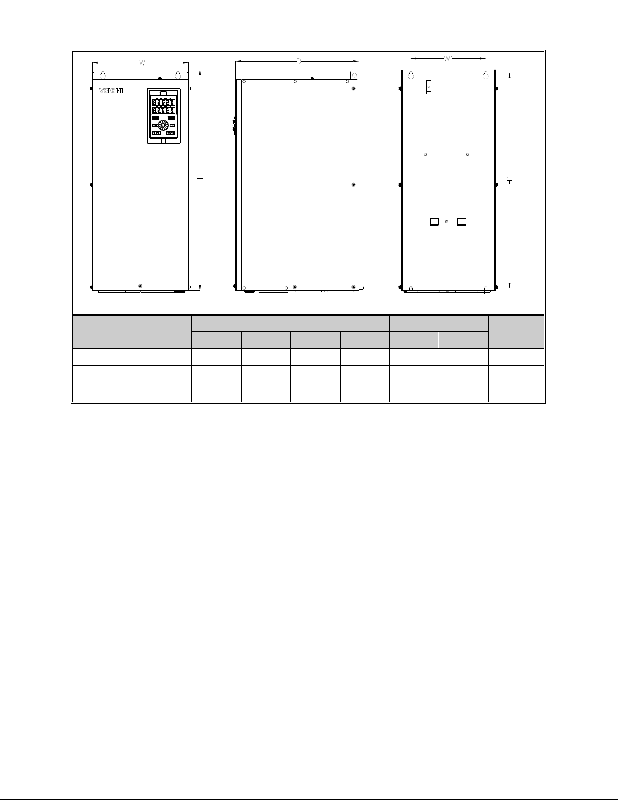
Overall Dimension of Inverter (Ste el)
安装直径
MODEL
Overall Dimension(m m)
Installation
Aperture
W H D H2 W1 H1
AC300-T3-045G/055P 225 523 290 500 176 509 ф7
AC300-T3-055G/075P 225 523 290 500 176 509 ф7
AC300-T3-075G/090P 240 570 340 535 176 551 ф9
Installati on Di amet er
6
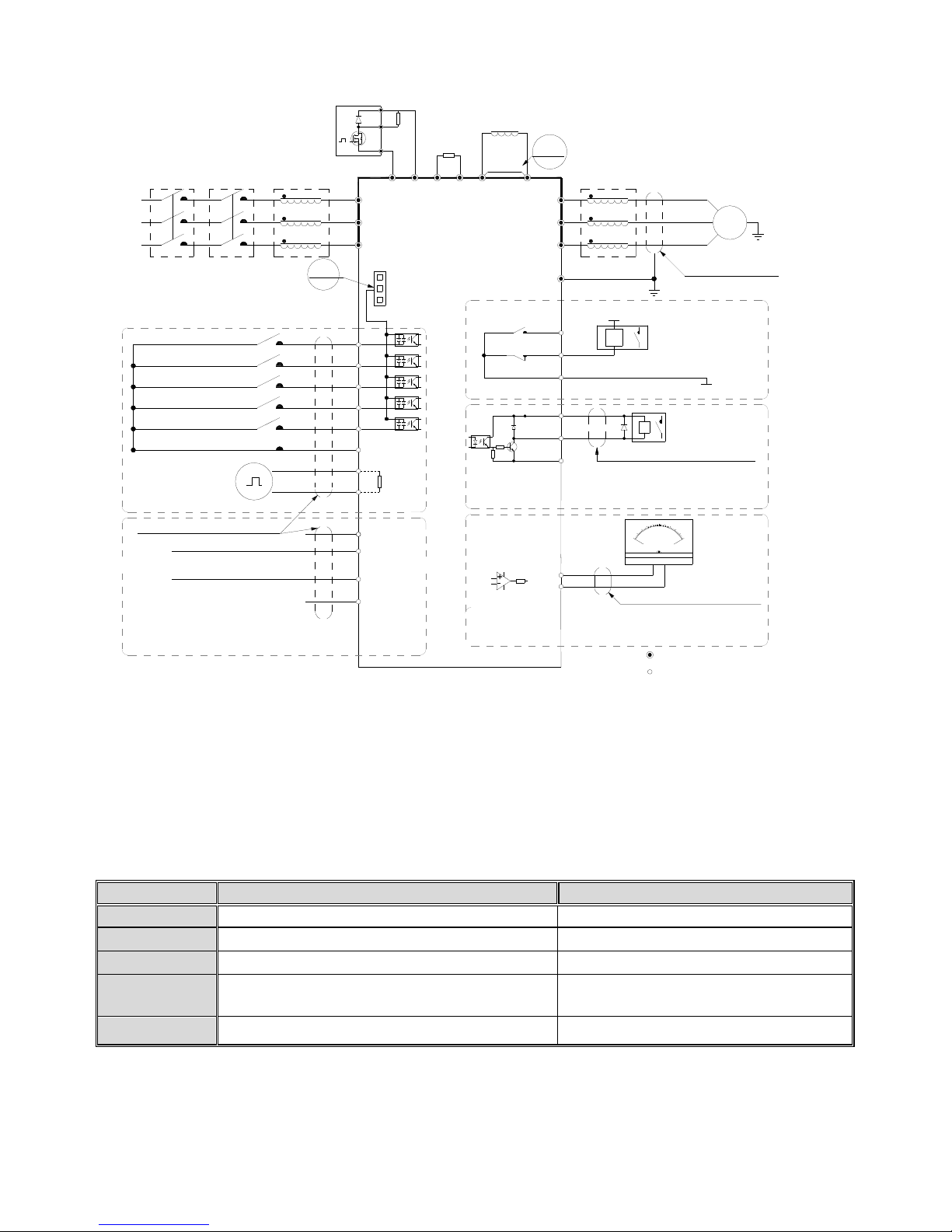
Standard Connection Diagram
Note2
Note:Function description in brackets is
factory default
Note1
Analog monitoring
signal output
TA
TB
TC
+24V
Y
Shielded cable (the
end close to VFD
grounding)
_
mA
2
0
10
0
-
+
V
W
U
M
~
Shielded cable or armoured cable
(the end close to VFD grounding)
E
(The grounding resistance
is less than 10 ohms)
W
V
U
Output Rector
External DC Rector
External
Brake
Resistor
Short
Piece
P1
+
( )
R
External Brake Unit
+10V
Frequency control input
R
T
S
AC POWER INPUT
GND
AI1
AI2
Shielded cable (the end close to
VFD grounding)
Multi function contact input
(REV JOG)
(FWD JOG)
(Reverse)
(Forward)
(Free STOP)
COM
X3
X4
X5
X1
X2
PB
( )
+
(-)
VFD
S
T
R
GND
A0
Coil
COM
Passive contact
output
AC220V
AC0V
Coil
MAX Output Of Contact:
3A/240VAC
5A/30VDC
1.MAX Output of +24V Port:DC24V/100mA
Note:When output type of AO port as
frequency and Voltage,
Maximum Output:2mA
2.Inner resistance of AI1/AI2 Port
1.MAX Output of +10V port :50mANote:
2.Max Output of Y Port :DC24V/50mA
Note:
represent control circuit terminals.
represent main circuit terminals;
Legend: 1.Symbol
Shielded cable
(the end close
to VFD grounding)
Input Rector
ContactorMCCB
+
( )
PUL
+24V
PLC
COM
Analog Voltage/Current quantity input
A+
B-
RS485 Differential
Communication
120Ω
Open collector(OC)
state output
Analog Voltage/Current quantity input
2.Symbol
Note: 1.When installing DC r eactor, make sure to dismantle the shor t connector be tween terminal P1 and (+).
2. NPN or PNP transistor signa l can be selected as input o f multi-functio n inpu t terminal (X1~X5/P UL) . Inver ter built-in power supply
(+24V terminal) or external po wer supply (PLC terminal) can be c hosen as b ias voltage. Factory setting ‘+24V’ sho rt connect with
‘PLC’, which locates between RJ4 5 and terminals.
3. Anal og monito r output is the special output for m eters suc h as fr equency meter, current meter and voltage meter. It can’t be used for
control operations such as fee dback contr ol.
4. As ther e are mu lti puls e styles, pleas e refer to the line conn ect mode de scription de tails.
●
Auxiliary Terminal Output Capacity
Terminal Function Definition Max Output
+10V 10V auxiliary powe r supply output, cons titutes loop with G ND. 50mA
A0 Analog monitor output, constitu tes loop wi th GN D. Max output 2mA as frequency, voltage signal
+24V
24V auxiliary power supply outpu t, constitutes loop with C OM.
100mA
Y
Collector open circuit ou tput; can set the action-o bject by
program.
DC24V/50mA
TA/TB /TC Passive connector output; can set the action-obj ect by program . 3A/240V AC
7
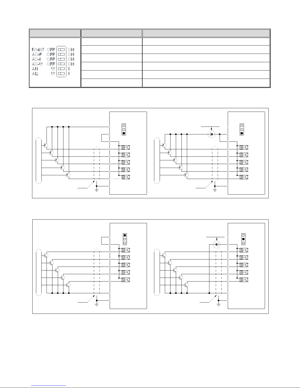
● Fu nction Speci fication of Swi tch Terminals
Switch T erminal Selecting P osition Function Specificati on
RS485 T erminal Resistor
RS485 Communication :connect with 120Ω terminal resistor
AO Output- frequency AO2: 0.0~100kHz frequency output
AO Output- Current AO2: 0~20mA current outpu t or 4~20mA current output
AO Output- Vol tage 0~10V voltage o utput
AI1 Input- Current/Voltage AI1: Input 0~20mA or 0~10V
AI2 Input- Current/Voltage AI2: Input 0~20mA or 0~10V
● Multi-function input point connection
PNP transistor connecti on mode
-
+
External power supply
E
X5
X3
X4
X2
X1
PLC
+24V
Enabled external 24V power supply
COMCOM
Enabled inner 24V power supply
+24V
PLC
X1
X2
X4
X3
X5
Shield Cable
E
External control signals
+24V
PLC
COM
+24V
PLC
COM
VFD VFD
External control signals
Shield Cable
NPN transistor connection mode
Enabled inner 24V power supply
+24V
PLC
X1
X2
X4
X3
X5
COM
Shield Cable
E
(Default short connected )
E
COM
X5
X3
X4
X2
X1
PLC
+24V
Enabled external 24V power supply
External control signals
Shield Cable
Note:
Jumper between"+24V"and"PLC" need be removed
when external 24V power supply was chosen.
External 24V power supply
+
-
+24V
PLC
COM
+24V
PLC
COM
VFD VFD
External control signals
8
Chapter 3 Keyboard layout and functions specification
●Keyboard Appe arance
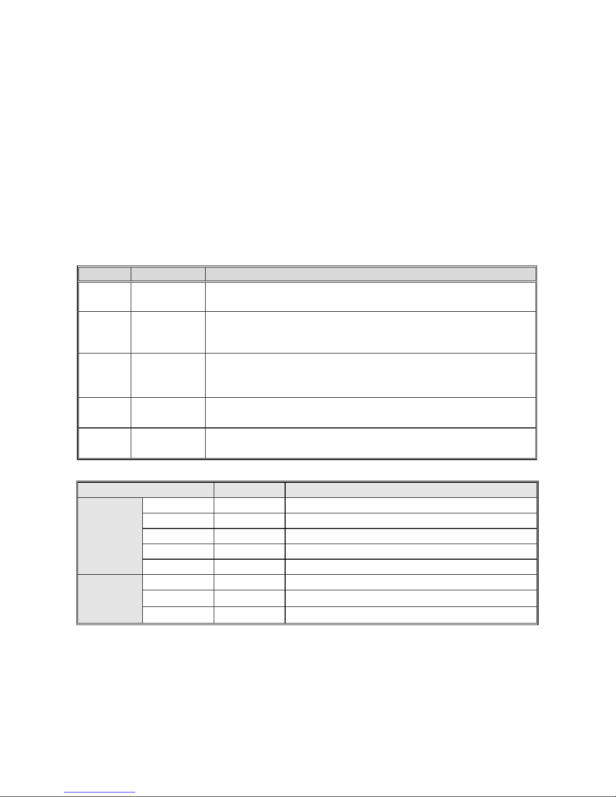
●Key function
Key Name Function
Menu key
Enter menu while standby or running . Presses this key to return while m odify param eter . W hile
standby or running, press for 1 sec to enter condition moni toring interface.
Confirm/Shift key
Press to modify parameter while in menu in terf ace. Press again to confirm a fter modifying ;
Press this key for 1 Sec to shift digit, and long press to cycle. Each digit flashes three time to
shift to next digit.
Up/down key
Select parameter group in menu interface. Modify par ameter in modify state. Modify g iven
frequency , ID given whi le at s tandby or moni toring sta te (While g iven freq uency, PID are set by
keyboard and [F4.09] needs to be set.
Run key
While run/stop is controlled by keyboard , press th is key, inverter forward runs, and the in dicator
is always on. While reverse, the indicator sparks.
Stop/reset key
Machine stops if press it while run/stop is controlled by keyboar d. Its effici ency range is defined
by [F4.08]. Inverter resets if press it in fault state (no reset if fault is not solved).
●Indicator Definition
Name State Meaning
Unit indicator
light
Hz Flas h / On Frequency unit
A On Current unit
V On Voltage unit
RPM On Motor speed unit
% Flash / On Percent unit
State
indicator light
RUN On Forward running
RUN Flash Reverse running
RUN Off Stop
9
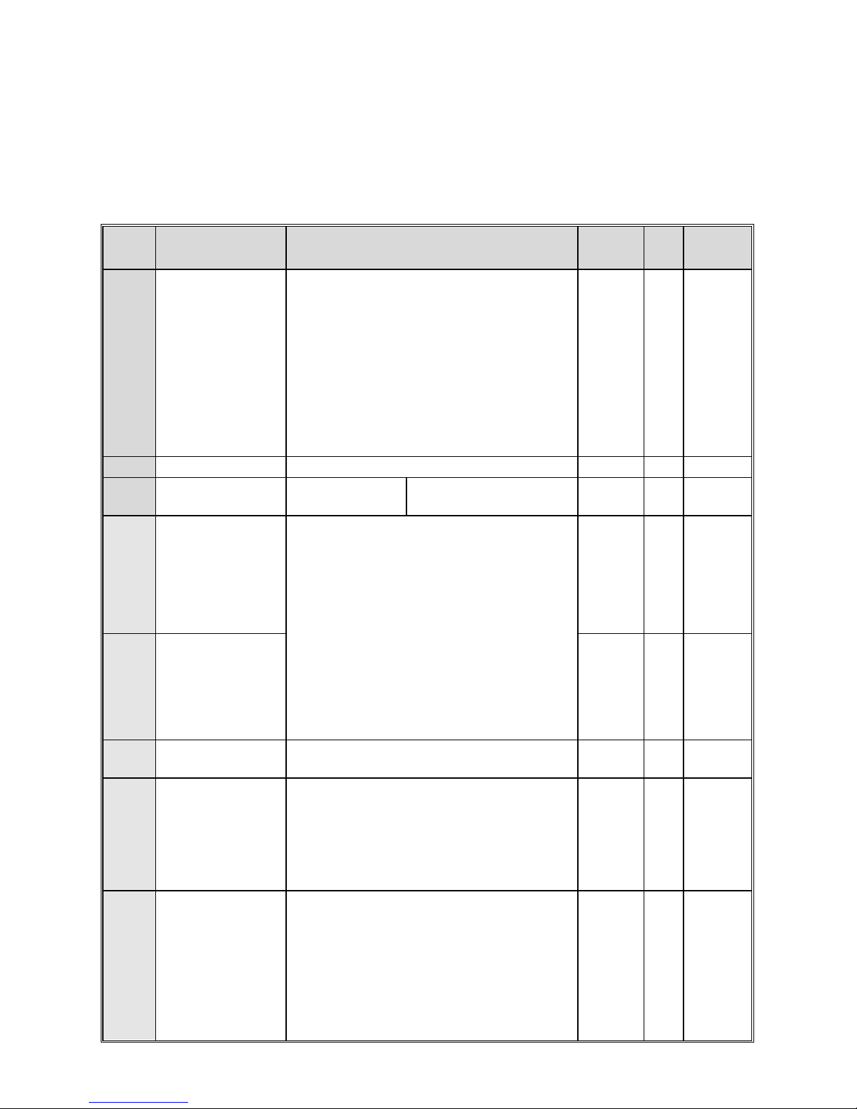
Chapter 4 Function Parameter Table
This chapter just provide s func tion parameter table. Specifica tions refer to AC200 technical manual or inquiry the compa ny.
“●”: Parameter can be changed in the running state.
“〇”: Parameter can’t be changed in the running state.
“×”: Parameter can be read only.
“–”: Factory setting parameter , only factory can set.
“※”: Parameter is related to the model.
4.1 Basic parameters
NO. Function description Range of settings and definition
Factory
default
Fea
ture
Address
F00.00 Motor control mode
Asynchronous motor control mode:
0: V/F control
3: High-performance VC without PG
4: High-performance VC with PG
Synchronous motor contro l mode:
6: High-performance VC without PG
7: VC with PG
Other control:
8:Voltage frequency separation outpu t
1/2/5: Reserved
0 〇 0x000
F00.01 Reserved 0x001
F00.02 Run command channel
0: Keyboard control
1: T erminal control
2: RS485 communication control
3: Reserved
0 ● 0x002
F00.03
Frequency given
source channel A
0: Keyboard number given
1: Reserved
2: Voltage/Current a nalog AI1 given
3: Voltage/Current a nalog AI2 given
4: Reserved
5: T erminal pulse PUL given
6: RS485 communication given
7: Terminal UP/DW control
8: PID control given
9: Program control (PLC) given
10: Optional card
11: Mul ti-steps speed giv en
0 ● 0x003
F00.04
Frequency given
source channel B
1 ● 0x004
F00.05
Frequency channel B
reference source
0: Max. output frequency as reference source
1: Set frequency of channel A as reference source
0 ● 0x005
F00.06
Frequency given
source selection
0: Channel A
1: Channel B
2: Channel A+ Channel B
3: Channel A- Channel B
4: Max. value of Channel A and Channel B
5: Min. value of Channel A and Channe l B
0 ● 0x006
F00.07
Running Command
Binding
LED“0”digit: keyboard command instruction binding
LED“00”digit: terminal command instruction binding
LED“000”digit: communication command instruction
binding
LED“0000”digit: optional card command instruction
binding
0 : no binding
1 : keyboard number given frequency
0000 ● 0x007
10
2 : Reserved
3 : Voltage /Current an alog AI1 given
4 : Voltage /Current an alog AI2 given
5 : Reserved
6 : Terminal pulse PUL given
7: RS485 communication given
8 : Terminal UP/DW cont rol
9 : PID control given
A: Program control (PLC) given
B: Optional card
C: Multi-steps speed given
F00.08
Keyboard digital setting
frequency
0~upper limit 50.00Hz ● 0x008
F00.09 Max frequency output upper limit~600.00Hz 50.00Hz 〇 0x009
F00.10
Upper limit frequency
source selection
0: Upper limit frequency digital given
1: Reserved
2: Voltage/Current a nalog AI1 give
3: Voltage/Current a nalog AI2 given
4: Reserved
5: T erminal pulse PUL given
6: RS485 communication given
7: Optional card
0 ● 0x00A
F00.1 1
Upper frequency limit
digital setting
Lower limit frequency~max frequency 50.00Hz ● 0x00B
F00.12 Lower limit frequency 0.00~upper limit frequency 0.00Hz ● 0x00C
F00.13
Lower limit frequency
running mode
0: Stop output, enter into pa use runnin g state
1: Run at lower limit frequency
1 〇 0x00D
F00.14 ACC time 1 0.01~650.00s
Model set
※ 0x00E
F00.15 DEC time 1 0.01~650.00s
Model set
※ 0x00F
F00.16
Rotary direction
selection
LED“0”digit: running direction takes the opposite
0: Direction unchanged
1: Direction takes the opposite
LED“00”digit: running direction prohibited
0:Forward and reverse commands are allowed
1: Only FWD command allowed
2: Only REV command allowed
LED“000”digit: frequency control direction selection
0: Invalid 1: Valid
LED“0000”digit: reserved
0000 〇 0x010
F00.17 G/P Model Setting 0:G T y pe 1:P Type 0 ● 0x011
F00.18 Reserved 0x012
F00.19 Parameter initialization
0: No action
1: Restore factory defaul t (not restoring motor p arameters)
2: Restore factory defaul t (restoring mo tor param eters)
3: Clear malfunction records
0 〇 0x013
 Loading...