

Veichi AC100-T3-7R5G, AC100-T3-R75G, AC100-T3-5R5G, AC100-T3-011G, AC100-T3-015G User Manual
...

Contents
Chapter 1 Overview……………………………………………………………………………………... 1
1.1 Safety Precautions……………………………………………………………... ….. ….. ….. .1
1.2 Technical Criterion …………………………………………………………………………….. 4
1.3 Specification of Expansion Card …………………………………………………………….. .7
Chapter 2 Before Use………………………………………………………………………………….. 8
2.1 Purchase Inspection………………………………………………………………………….. 8
2.2 Nameplate ……………………………………………………………………………………... 8
2.3 Standard Models and Rated Parameters……………………………………………………9
Chapter 3 Installation and Wiring……………………………………………………………………. 10
3.1 Safety Precautions…………………………………………………………………………. …10
3.2 Dealing Methods for Inverter after Long-term Storage ………… ………………………….11
3.3 Stable Running Environment for Inverter……………………………………………………11
3.4 EMI Protection………………………………………………………………………………... 12
3.5 Machinery Installation………………………………………………………………………….15
3.6 Electrical Installation…………………………………………………………………………. .23
Chapter 4 Basic Operation and Trial Run…………………………………………………………..37
4.1 Safety Precautions…………………………………………………………………….……… 37
4.2 Keyboard Layout and Functions Specification………………………………………………38
4.3 Basic Operation…………………………………………………………………………………41
4.4 LED Keyboard Operation Specification………………………………………………………43
4.5 Trial Run………………………………………………………………………………………... 48
Chapter 5 Fault Diagnoses and Processing……………………………………………………… 56
5.1 Fault Types……………………………………………………………………………………. .56
5.2 Fault Information and Details ……………………………………………………………... . .56
5.3 Fault Diagnoses and Treatment Measures …………………………………………………61
Chapter 6 Regular Inspection and Maintenance……………………………………………………67
6.1 Safety Precautions……………………………………………………………………………. 67
6.2 Inspection………………………………………………………………………………………. 67
6.3 Maintenance………………………………………………………………………………... ... 69
Chapter 7 Peripherals and Options………………………………………………. 72
7.1 Safety Precautions………………………………………………………………………... …. 72
7.2 Peripherals……………………………………………………………………... ………………72
7.3 The Use of Peripherals …………………………………………………………. …………. . 74
Chapter 8 Function Parameter Specification ............................................................................. 77
8.1 Basic Parameters ............................................................................................................ 77
8.2 Running Control Parameter ............................................................................................. 87
8.3
Quantum Digital Terminal Parameter .............................................................................. 93
8.4 Analog Terminal Parameter ........................................................................................... 108

8.5 Keyboard and Display Parameters ................................................................................ 113
8.6 Motor Parameters .......................................................................................................... 117
8.7 VC Control Parameter ................................................................................................... 119
8.8 Torque Control Parameters ........................................................................................... 123
8.9 V/F Control Parameters ................................................................................................. 125
8.10 Malfunction and Protection Parameters ...................................................................... 128
8.11 PID Parameters ........................................................................................................... 133
8.12 Multi-step, PLC Function and Swing Frequency Parameters ...................................... 138
8.13 Communication Control Function Parameters ............................................................ 143
Chapter 9 Appendix .................................................................................................................... 149
9.1 Appendix 1: Function Parameter Table ......................................................................... 149
9.2 Appendix 2: RS485 Communication Protocol ............................................................... 188
9.3 Appendix 3: PG Card Manual ........................................................................................ 196
9.4 Appendix 4: Profibus-DPcard Manual ........................................................................... 204
9.5 Appendix 5:LCD Keyboard ............................................................................................ 206
9.6 Appendix 6: CANopen Card Manual ............................................................................. 210
AC100 HIGH-PERFORMANCE VC INVERTER MANUAL OVERVIEW
1
Chapter 1 Overview
Thanks for using AC100 high-performance VC frequency inverter produced by Shenzhen Veichi Electric Co., Ltd. This
manual explains the proper way of using the product. Please read carefully (installation, wiring, operation, maintenance,
checking, etc) before use.
1.1 Safety Precautions
To ensure safe, reliable and rational use of this product, please fully understand the safety precautions described in this
manual before use.
Warning Signs and Meanings
This manual uses the following marks to indicate the importance of security. If these precautions are not followed,
accidents such as personal injury, damage of the product and associated systems might occur.
Danger: Wrong operation may cause death or major accident.
Warning: Wrong operation may cause death or major accident.
Caution: Wrong operation may cause minor injury.
Important: Wrong operation may cause damage to the inverter and related system
Warning Signs Position
Drawing 1:Warning positions on crust of AC100 series inverter
Warning position 2
Warning position 1
AC100 HIGH-PERFORMANCE VC INVERTER MANUAL OVERVIEW
2
Operation Qualification
All the products must be performed by trained professionals for installation, wiring, operation, maintenance and other
operations. The "trained professionals" referred in this manual must undergo professional training, being familiar with
the installation, wiring, operation and maintenance of the equipment and must be able to handle with all kinds of arising
emergencies.
Safety Guidance
Safety rules and warning signs are set for users’ safety and to prevent personal injury, damage of product and
associated systems; to ensure safe, reliable and rational use of this product, please fully understand the safety
precautions described in this manual before use.
Safety rules and warning signs are divided into the following categories: routine guidance, transportation and storage
guidance, installation guidance wiring, operation and maintenance guidance, as well as dismantlement and disposal
guidance
● Routine Guidance
● This product contains dangerous voltage and it controls the movement mechanism with
potential danger; there might be accidents like personal injury and damage to the product and
associated systems if requirements in this manual are not followed.
● Only trained personnel should operate this product, and before using the product in this
manual the personnel should be familiar with all safety instructions and regulations of the
operation; proper operation and maintenance are the key to achieve security and stability of
the product.
● No wiring when power on. Otherwise, there might be danger of electric shock; when operating
wiring, inspection, maintenance and other operations, please turn off the power of all related
equipment and make sure the main circuit DC voltage has dropped to security level, and wait
for five minutes before any relevant job.
● Away from children and public.
● This product could only be used in special areas specified by the manufacturer and should not
be used in fields like emergency, rescue, marine, medical, aerospace, nuclear facilities
without permission.
● Unauthorized alteration or use of accessories not sold or recommended by the manufacturer
may cause a malfunction.
● Please make sure this manual is in the final user’s hand before use.
● Before installation and debugging please carefully read and totally understand these safety
regulation and warning signs.
● Transportation and Storage Guidance
●Correct transportation, storage, installation, and careful operation and maintenance are
essential for the safe operation of the inverter.
● In transport and store process, make sure the inverter is free from shock and vibration. It must
be stored in places dry without corrosive air and conductive dust, and the temperature must
be lower than 60℃.
AC100 HIGH-PERFORMANCE VC INVERTER MANUAL OVERVIEW
3
● Installation and Wiring Guidance
● Only trained personnel can operate.
● Power lines, motor lines, control lines must be connected tightly, and the ground terminal
must be grounded, and the grounding resistance must be less than 10Ω.
● Before opening the inverter panel, turn off the power of all related equipment, and make sure
the main circuit DC voltage has dropped to a safe level, and wait five minutes before any
relevant job.
● Human body electrostatic would seriously damage the inner sensitive components. Before
operation, please follow ESD measures. Otherwise, there might be danger of inverter
damage.
● The voltage of the inverter outputs in form of pulse wave, and if capacitor that improve power
factor or varistor that is against thunder is installed on the output side, make sure to dismantle
them or modify them to the input side of the inverter.
● No switch components such as breaker and contactor at the output side. (If there must be
one, please make sure the output current is 0 while the switch acting).
● The power supply cable and motor cable specifications must satisfy all conditions in table 3-7
and table 3-8.
● Running Guidance
● Inverter runs at high voltage. So dangerous voltage is in some components inevitably.
● No matter where the fault is, there is danger of serious accident, even human body injury
which means dangerous malfunction possibility. So there must be additional external
preventing measures or other safety devices, such as independent current limiting switch,
machinery fense and so on.
● In order to ensure that the motor overload protection can operate correctly, motor parameters
must exactly match the motor in use.
● Maintenance Guidance
●Maintenance and service of this product can only be done by the service sectors or authorized
service center of Veichi Electric Co., Ltd or professional person trained and authorized by
Veichi. And these personnel should be familiar with the safety warnings and proposed
operating essentials referred in this manual.
● Any defective components must be changed in time.
●
Before opening the equipment, be sure to disconnect the power, and make sure the main
circuit DC voltage has dropped to a safe level, and wait five minutes before any relevant job
● Dismantlement and Disposal Guidance
●The inverter's packaging is reusable, please keep the packaging for future use or please
return it to the manufacturer.
● Dismantlement of metal components can be recycled.
● Some components such as electrolytic capacitor are harmful to the environment. Please
dispose according to the requirements of environmental protection departments.
AC100 HIGH-PERFORMANCE VC INVERTER MANUAL OVERVIEW
4
1.2 Technical Criterion
Items Criterion
Power
input
Voltage, frequency
Single-phase 220V 50 / 60Hz three-phase 380V 50 / 60Hz
Three-phase 220V 50 / 60Hz three-phase 660V 50 / 60Hz
Allowable fluctuations
Voltage fluctuation: 320V ~ 440V;
Voltage unbalance rate: <3%;
Frequency fluctuation: ± 5%
Distortion rate: meet IEC61800-2 requirements
Closing inrush current Lower than rated current
Power factor ≥0.94(with DC reactor)
Inverter efficiency ≥96%
Output
Output voltage
Under nominal conditions Output: 3 phase, 0 to the input voltage, the error
Output frequency range 0 ~ 320 Hz (320 Hz or more can be factory customized)
Output frequency accuracy
Error does not exceed 0.01Hz (digital setting) or 0.2% of maximum
frequency (analog reference)
Overload capacity
150% of rated current for 1 minute; 180% of rated current for 10 seconds;
200% of rated current for 0.5 seconds;
Main
Control
performance
Motor control mode
Induction motors: vector control without PG, PG vector control, VF control
Permanent magnet synchronous: no PG vector control, vector control with
PG
Modulate mode
Optimization space vector PWM modulation, continuous adjustment, not
continuous adjustment automatically switch
Carrier frequency 0.6~15.0kHz,randomized carrier-wave
Speed range
VC with PG: 1: 1000
VC without PG (asynchronous): 1: 100
VC without PG (synchronous): 1:50
Steady speed accuracy
VC without PG (asynchronous and synchronous): ≤ 1% rated synchronous
speed
VC with PG (asynchronous and synchronous): ≤ 0.02% rated synchronous
speed
Starting torque
VC without PG (asynchronous): 0.5Hz provide 180% rated torque
VC without PG (synchronous): 2Hz to provide 100% of the rated torque
VC with PG (synchronous and asynchronous): 0Hz provide 200% of the
rated torque
Torque response
VC without PG (synchronous and asynchronous): ≤20ms
VC with PG (synchronous and asynchronous): ≤10ms
Frequency accuracy Digital setting: 0.01Hz; Analog setting: Maximum frequency × ± 0.2%
Frequency resolution Digital setting: 0.01Hz; Analog setting: Maximum frequency × 0.05%
Basic
functions
DC braking capacity
Starting frequency:0.00~50.00Hz
Braking time:0.0~60.0s
Braking current:0.0~150.0% rated current
AC100 HIGH-PERFORMANCE VC INVERTER MANUAL OVERVIEW
5
Torque upgrade capacitance
Auto torque upgrade 0.0%~100.0%
Manual torque upgrade 0.0%~30.0%
V/F curve
VF linear curve, custom multi VF curve, square VF curve;
VF power 1.1-1.9 arbitrary curve;
Acceleration/Deceleration
curve
Two ways: one linear acceleration and deceleration, S-curve acceleration
and deceleration;
Four sets of acceleration and deceleration time, time unit 0.01s, longest
650.00s, the benchmark optional;
Rated output voltage
Using the compensation function of power supply voltage. When the motor
rated voltage range is 100%, it can be set to any value within the range of
50-100% (output voltage can’t exceed the input voltage)
Voltage auto-adjustment
When the grid voltage fluctuates, the constant output voltage can be
automatically maintained.
Energy-saving running
Depending on the load condition, automatically optimizing the output
voltage to save energy.
Current auto-limiting
Auto-limit the current while running to prevent frequent over current break
trouble.
Instant power off treatment
When instant power off, control the bus voltage to realize uninterrupted
operation.
Standard functions
Superposition of main and auxiliary frequency source, running the
command bundle, starting frequency, vector pre-excitation starting, start /
stop of DC braking, speed tracking and power-down re-starting, reverse ban
and reversing dead time setting, zero speed torque holding, jog operation,
frequency hopping, separately set the emergency stop time, FDT detection,
timer function, torque control, flux braking and dynamic braking, failure
recovery, the last three failure record, process PID controller, multi-velocity
and PLC program control, 485 communication interface;
Frequency setting channel
Keyboard digital setting, keyboard potentiometer, analog voltage terminal
VS, analog voltage / current terminals AI, analog current terminal AS, given
and multi-channel communications terminal selection, main and auxiliary
channel combinations
Feedback input channel
Voltage terminal VS1, the voltage / current terminals AI, current terminals
A
S, communication given, pulse input PUL
Running command channel Operation panel given, external terminal given, communication given.
Input command signal
Start, stop, FOR/REV, JOG, multi-velocity, free stop, reset,
Acceleration/Deceleration time selection, frequency set channel selection,
external fault alarm.
External output signal
2 relay outputs, 1-collector output;
0 ~ 10V output, 4 ~ 20mA / 0 ~ 20mA output;
Pulse frequency output;
AC100 HIGH-PERFORMANCE VC INVERTER MANUAL OVERVIEW
6
Protection function
Bus overvoltage, mains under voltage, inverter over-current, module failure,
inverter overload, motor overload, current detection zero drift failure, Hall
failure, E2ROM failure, motor grounding failure, input phase failure, output
phase failure, inverter overheating, communication failure, PG card failure,
PG disconnection failure, motor parameter self-tuning failure;
Special Functions
VC mode
2 modes: 1st mode providing high-performance speed effect; 2ed mode
providing lower and simple performance testing method;
Auto-learning
Asynchronous motors, synchronous motors static parameter learning,
rotation parameter learning;
Static self-learning induction motors all parameters; PG vector control
encoder self-learning;
Supporting multiple
encoders
Incremental encoder (5V, 12V power supply, frequency dividing output),
resolver, SinCos encoders, absolute encoders;
VF separation
function
Frequency, voltage can be independently given and regulated, supporting
multi-channel given way;
T erminals, Analog
quantity
Providing 4-way virtual X terminals, 4-way virtual Y terminals; supporting
delay adjustment of terminal rising and falling;
Extending 3-way X terminals by analog quantity;
Providing more than two points analog quantity for analog calibration;
Motor grounding
short circuit detection
Can detect whether the motor is shorted to ground and the electricity can be
automatically detected;
Servo control
Supporting basic functions like synchronous and asynchronous servo
control, pulse tracking, zero servo positioning servo index location,
supporting quadrature pulse given;
Telecommunication
network
supporting 485 / Modbus protocol, CANopen protocol, profibus-DP protocol;
Modbus freedom protocol, CAN custom protocols, networking and linkage
control between WEICHI inverters can be realized;
Remote and
monitoring function
Supporting remote upgrading, remote monitoring, remote locking function,
can be connected to WEICHI 3G module;
Supporting virtual oscilloscope monitoring and debugging;
Keyboard
display
LED display
Single row 4 digital tube display Can monitor one state variable
Two row 5 digital tube display Can monitor two state variables
Parameter copy
Function code information of frequency inverter can be uploaded and
transferred to realize fast parameter copy.
State monitoring
Output frequency, given frequency, output current, input voltage, output
voltage, motor speed, PID feedback, PID given value, module temperature,
input and output terminal status
Environment
Installation site Indoor, altitude ≤1000m, no corrosive air or direct sunshine
Temperature, humidity -10 ~ +40℃ 20%~90%RH(no condensation)
Vibration Under 20Hz≤0.5g
Storage temperature -25~+65℃
Installation method Hanging type, cabinet type
Protection level IP20
Cooling method Forced air cooling

AC100 HIGH-PERFORMANCE VC INVERTER MANUAL OVERVIEW
7
1.3 Expansion/SD Card Specification:
There’s a variety of optional expansion/SD card for AC100, specified in the table below:
Expansion/SD Card Type Model Description
Ordinary photoelectric ABZ
encoder PG card
PG01_ABZ_xx_xx
Applicable for ordinary photoelectric encoder; 5V,
12V power output, OC, divided signal output are all
optional;
Ordinary photoelectric UVW
encoder PG card
PG01_UVW_xx_xx
Applicable for photoelectric encoder with UVW
signals or wire-saving type UVW encoder.
Resolver PG card PG01_RT
Applicable for resolver.
Terminal expansion card EXIO_01
Applicable for increasing the number of common
input terminals, relays, and analog quantity.
Air compressor expansion card
EXIO_02
Applicable for the control of air compressor.
ⅡPG card PG02_ABZ_xx
Applicable for speed measuring and quadrature
pulse given.
DP expansion card ACDP03
Applicable for expansion of profibus-DP
telecommunication
CANopen expansion card CAN01
Applicable for expansion of CANopen
telecommunication
3G telecommunication
expansion card
S200-GPS
Applicable for remote monitoring, software upgrades,
remote locking
Servo expansion card
EXSV_01
Providing differential input and output terminals and
RS232 communication interface.
AC100 HIGH-PERFORMANCE VC INVERTER MANUAL BEFORE USE
8
Chapter 2 Before Use
2.1 Purchase Inspection
On receiving your order, please check the package and confirm intact before opening, and check if there’s any damage,
scratch or dirt (damages caused during transportation are not within the company's warranty). If there’s any damage
caused during transportation, please contact us or the transport company immediately.
After confirming the receipt of the goods intact, please re-confirm if the product and your order are consistent. Model of
the product is on the "MODEL" column. If you find the product model is not the one you ordered, please contact the
dealer you purchased the product or the sales department of VEICHI immediately.
2.2 Nameplate
Nameplate Position and Content
Input
Inverter model
Output
Power range
Series NO.
Drawing2-1:AC100 Series Inverter Nameplate Position
Model Specification
AC100 series
Single-phase
S
T
Symbol
Inverter series
G
(4)
Motor power(kW)
Phase
3-phase
Type
(3)
2R2
(2)
T
(1)
AC100
(5)
3
220V
Voltage
Symbol
2
3
380V
Symbol
G
General
(Pls refer drawing 2-1 2-2)
Drawing 2-2:Meaning and Naming Rules of AC100 Series Inverter Nameplate
AC100 HIGH-PERFORMANCE VC INVERTER MANUAL BEFORE USE
9
2.3 Standard Models and Rated Parameters
Single phase 220V
Table 2-1:AC100 Single Phase 220V Series Inverter Models and Rated Parameters
Three phase 380V
Table 2-2:AC100 Three Phase 380V Series Inverter Models and Rated Parameters
Model
Max adaptive
motor
Rated current
Model
Max
adaptive
motor
Rated
current
AC100-S2-R40G 0.4kW 2.5A AC100-S2-1R5G 1.5kW 7A
AC100-S2-R75G 0.75kW 4A AC100-S2-2R2G 2.2kW 10A
Model
Max adaptive
motor
Rated current
Model
Max
adaptive
motor
Rated
current
AC100-T3-R75G 0.75kW 2.5A AC100-T3-110G 110kW 210A
AC100-T3-1R5G 1.5kW 3.7A AC100-T3-132G 132kW 250A
AC100-T3-2R2G 2.2kW 5A AC100-T3-160G 160kW 310A
AC100-T3-004G 4kW 10A AC100-T3-185G 185kW 340A
AC100-T3-5R5G 5.5kW 13A AC100-T3-200G 200kW 380A
AC100-T3-7R5G 7.5kW 17A AC100-T3-220G 220kW 415A
AC100-T3-011G 11kW 25A AC100-T3-250G 250kW 470A
AC100-T3-015G 15kW 32A AC100-T3-280G 280kW 510A
AC100-T3-018G 18.5kW 38A AC100-T3-315G 315kW 600A
AC100-T3-022G 22kW 45A AC100-T3-355G 355kW 670A
AC100-T3-030G 30kW 60A AC100-T3-400G 400kW 750A
AC100-T3-037G 37kW 75A AC100-T3-450G 450kW 800A
AC100-T3-045G 45kW 90A AC100-T3-500G 500kW 860A
AC100-T3-055G 55kW 110A AC100-T3-560G 560kW 990A
AC100-T3-075G 75kW 150A AC100-T3-630G 630kW 1100A
AC100-T3-090G 90kW 180A AC100-T3-700G 700kW 1260A
AC100 HIGH-PERFORMANCE VC INVERTER MANUAL INSTALLATION AND WIRING
10
Chapter 3 Installation and Wiring
3.1 Safety Precautions
This section specifies the various considerations necessary for reliable and safe operation of the product by users.
Inverter
●When the inverter is installed in closed cabinet, please ensure the temperature at the air-in
port below 40℃ by way of cooling fans or air conditioners and other cooling equipment to
ensure the safe and reliable operation of the inverter.
●When installing, please cover the inverter with cloth or paper to prevent metal dust, oil, water
and others. And remove these cover carefully after working.
● Please follow the ESD regulations when operating the inverter, otherwise, the inverter may
be damaged.
●If several inverters are installed in a cabinet, enough space must be set aside on the upper
part of the inverter in order to change the cooling fan.
●Inverter can’t work over rated range. Otherwise, the inverter may be damaged.
●When transporting the inverter, please hold the case firmly. There might be danger of inverter
main body falling, personnel injury or inverter damage if only holding the pre-cover.
Motor
●Different motor has different max allowable running speed. Motor can’t run over the max
allowable running speed.
●When inverter is running at low speed, the motor auto-cooling effect would seriously decrease.
If motor runs at low speed for long term, it will be damaged for overheating. If needed, please
use special motor for inverter.
●When constant speed machinery runs at inconstant speed, there might be sympathetic
vibration. Please install vibration-proof rubber under motor rack or use jumping frequency
control function.
●When using frequency inverter or working frequency power supply to drive, the torque
characteristics are different. Please do confirm the torque characteristic of the equipment
connected.
●The rated current of shift gear motor is different from that of standard motor. Please confirm
and choose the right frequency inverter. Moreover, please do switch the pole when the
inverter input current is 0. Otherwise, it may bring inverter damage.
●The rated current of diving motor is higher than that of standard motor, please confirm and
choose the right inverter.
●When the wiring distance between motor and inverter is far, the max torque of the motor
would reduce due to voltage drop. So please use cable thick enough when the distance
between the motor and the inverter is long.

AC100 HIGH-PERFORMANCE VC INVERTER MANUAL INSTALLATION AND WIRING
11
3.2 Dealing Methods for Inverter after Long-term Storage
If the inverter storage time is over one year, the aluminum capacitor in the inverter must be pre-charged again and
make sure the aluminum capacitor characteristic recovered before installation. For specific method, please follow the
grads in the chart below and give more than 30 mins corresponding proportional voltage for every grad when the
inverter is no-load.
If the input voltage of one grad is at the critical point of contactor, fan or other equipments, please increase or reduce
the corresponding input voltage for the grad to avoid any related components working under critical state.
Chart 3-1: Dealing Methods for Inverter after Long-term Storage
3.3 Stable Running Environment for Inverter
Installation environment is very important to maximize the performance of this product and maintain long-term function,
so please install the product in the environment as required in the following chart.
Environment Requirement
Installation site Indoor without direct sunshine
Operating
temperature
-10 ~ +40℃(hanging type)
-10 ~ +45℃(cabinet type)
Storage temperature -20 ~ +60℃
Environment humidity <95%RH, no condensation
Surroundings
Please install the inverter in place as follows:
● Place without oil mist, corrosive gases, flammable gas, dust, etc.
● Place where metal dust, oil, water would not get inside the inverter (please do not install
inverter on flammable material such as wood, etc).
● Place without radioactive material or flammable material.
● Place without poisonous gases or liquid.
● Place with little salt corrosion.
● Place without direct sunshine.
Altitude <1000m
Vibration
<10~20Hz:9.8m/s2
<20~55Hz:5.9m/s2
Installation and
cooling
● Inverter must be installed vertically and longitudinally, and it can’t be installed horizontally.
● Please independently install high heating equipments such as braking resistor and it can’t be
installed in the same cabinet with inverter. Installation of high heating equipments at the air-in
port of the inverter is strictly prohibited.
Chart 3-1:AC100 Series Inverter Running Environment Condition
AC100 HIGH-PERFORMANCE VC INVERTER MANUAL INSTALLATION AND WIRING
12
●To improve product reliability, please use the inverter where temperature would not change suddenly; when using in a
closed cabinet, cooling fan or air conditioning for cooling is needed to prevent the internal temperature from
exceeding allowed temperature; please avoid freezing of the inverter since low temperatures may cause malfunction
of some devices due to freezing.
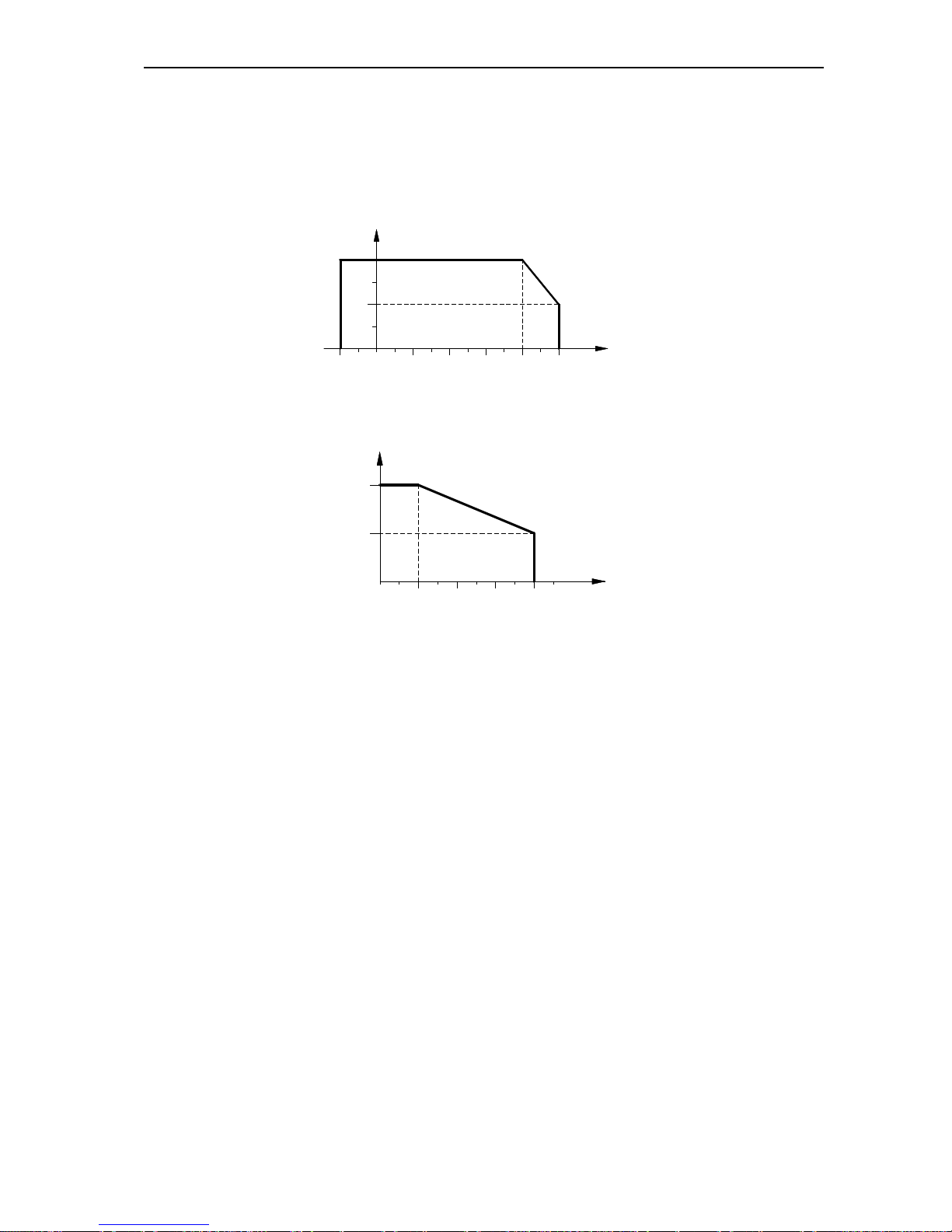
● Derate according to the chart when temperature exceeds limit.
30
25
100
75
50
4020100-10 50
TEMPERATURE(℃)
PERMIT OUTPUT CURRENT(%)
Chart 3-2:AC100 Series Inverter Derating Curve When Exceeding Permitted Temperature
● Derate according to the chart when altitude exceeds limit.
0
1000 2000 4000
80
100
3000 ALTITUDE(M)
PERMIT OUTPUT CURRENT(%)
Chart 3-3:AC100 Series Inverter Derating Curve When Exceeding Permitted Altitude
3.4 EMI Protection
The designing features of inverter allow it to run with strong electromagnetic interference. Generally, if the quality of the
installation is good, the safe and trouble-free operation of the inverter can be guaranteed. Please implement installation
according to the following rules to ensure reliable and effective installation of inverters and avoiding electromagnetic
interference.
● Make sure that all equipments in the cabinet have been connected reliably to the public Y-type earth point or earth
bus with thick and short cable. The motor earth should be as close as possible. Please do not connect the motor
shell to earth terminal of the inverter or the protective area of control system.
● Make sure that all devices connected to the inverter are connected to the same earth net or Y-type earth point with
thick and short cable.
● It would be better for conductors to be flat and multi-core since they have lower impedance at high frequencies.
● When cutting off the tip, the cable should be as neat as possible to make sure that the unscreened wires are as short
as possible.
● Wiring of control cable should be away from the power supply cable and motor cable as far as possible; separate
trunk should be used and a 90º vertical cross must be used when the supply power cable and the motor cable
intersect.
● Make sure that the contactor should be installed in a cabinet with a surge suppressor. Alternatively, the AC contactor
coil is connected with 'R-C' damping circuit, using a coil voltage corresponding varistor; the DC contactor coil is
connected with 'flywheel' diodes or pressure thermistor type devices corresponding to the coil voltage, which is
particularly important when the contactor frequently operates and when contactor is controlled by the output relay of
the inverter.
● Cable connected to motor should be shielded cable or armored cable. The two barriers are earthed reliably by cable
AC100 HIGH-PERFORMANCE VC INVERTER MANUAL INSTALLATION AND WIRING
13
earthing card.
● Installation of 'Input Noise Filter' can reduce electromagnetic interference from other devices of the grid side, 'Input
Noise Filter' must be as close to the inverter input terminals, at the same time, the filter must earth reliably as the
inverter.
● Installation 'output side noise filter' can reduce interference from radio interference and induction noise. 'Output side
noise filter' must be as close to the inverter output terminals, at the same time, the filter must earth reliably as the
inverter.
● Control circuit cable should be shielded cables all the time;
● Adding zero phase reactor in power supply wire near inverter input terminal, adding zero phase reactor in the motor
wire near inverter output terminal and adding zero phase reactor in control wire near inverter control terminal to
efficiently reduce electromagnetic interference to the inverter.
● Earth
Right and reliable earth is the basic condition of safe and reliable running of the product. For right earth, please read the
following notice carefully.
●To avoid electric shock, earth cable should be the size as specified in the technical
standards for electrical equipment. And cable length should be as short as possible.
Otherwise, leakage current of inverter would cause unstable potential of the earth
terminal which is far from the earth point, and electric shock accident would happen
frequently.
● Be sure to ground the ground terminal. Grounding resistance 10Ω or less, it may
cause injury or death
●Earth terminal must be earth. Earth resistance must be below 10Ω. Otherwise, there
is danger of injury and death.
●Please do not share earth cable with welder or other big current/pulse power
equipment. Otherwise, inverter would act abnormally.
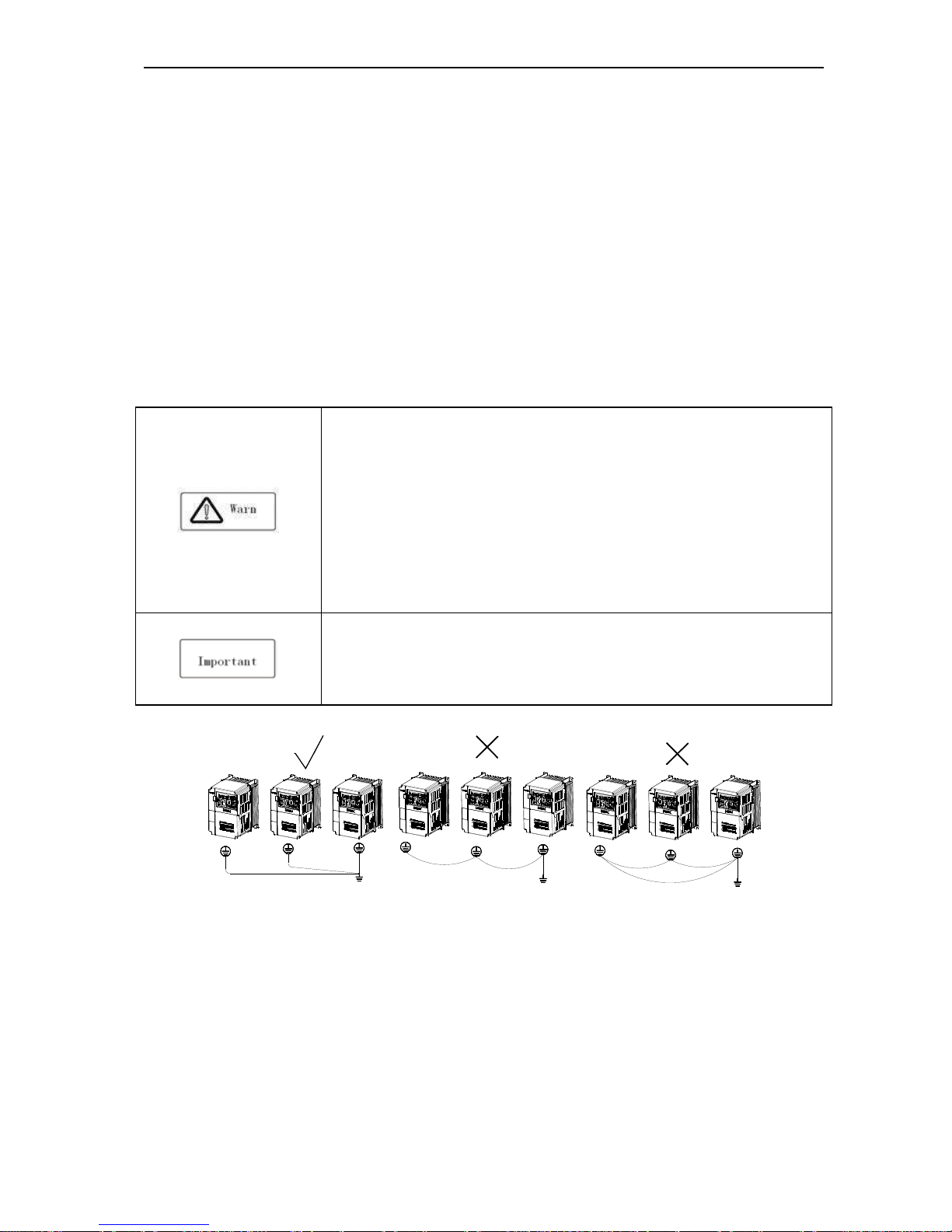
●When multi inverters are used at the same time, please do not wind the earth wire to
loop-type. Otherwise, inverter will act abnormally.
Chart 3-4: Multi AC100 Series Inverters United Earth
AC100 HIGH-PERFORMANCE VC INVERTER MANUAL INSTALLATION AND WIRING
14
Chart 3-5:AC100 Series Inverter System Earth
Note: motor must earth as close as possible. Motor shell can’t be connected to the inner earth terminal of the inverter
and it can’t share the earth net with the control system either.
●Power cable, motor cable, control cable of inverter
Shielding layer (reticulate/armored) should be winded reliably by cable earth card and then fixed to inverter earth piece
by bolt. Please refer to the following chart.
Chart 3-6:Cable Earth Card for Cable Earth
● Correspondence between inverter and motor cable length and carrier frequency
When wiring distance between inverter and motor is long (especially low-frequency output), cable voltage drop will
cause the motor torque reduction. Moreover, high-frequency leakage current will increase, thereby causing an increase
of inverter output current, which would cause the inverter over current trip. And the current detection accuracy and
running stability would be seriously affected. Please refer to the cable length in the following table to adjust the carrier
frequency. When system requires the wiring distance to be more than 100m, please adopt distributed capacity reduce
measure (Such as “no metal conductor covers cable”, “wire each phase cable apart” and so on)
Cable length <20m 20~50m 50~100m >100m
Carrier frequency 0.6~16kHz 0.6~8kHz 0.6~4kHz 0.6~2kHz
Chart 3-2:Correspondence between Inverter and Motor Cable Length and Carrier Frequency
AC100 HIGH-PERFORMANCE VC INVERTER MANUAL INSTALLATION AND WIRING
15
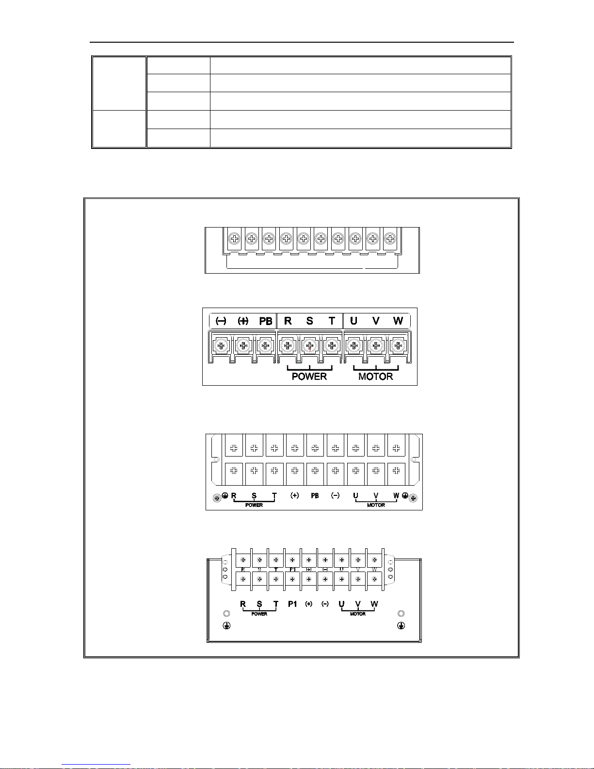
3.5 Machinery Installation
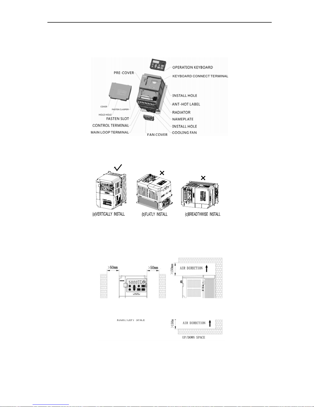
Installation Notice and Related Requirement
● AC100 inverter components
Chart 3-7:AC100 Series Inverter Components
● Installation Direction
To prevent reduction of inverter cooling effect, please do install the inverter longitudinally-mounted.
Chart 3-8:AC100 Series Inverter Installation Direction
● Installation Space
Single machine installation: to ensure enough ventilation and wiring space for inverter cooling, please follow installation
conditions as follows. The back of the inverter should stick to the wall so that the surrounding air of radiator can flow
freely to ensure the cooling effect.
Chart 3-9:Single AC100 Series Inverter Installation Space
Multi inverters paratactic installation: when installing multi inverters in cabinet, please ensure installation space as
required below.
AC100 HIGH-PERFORMANCE VC INVERTER MANUAL INSTALLATION AND WIRING
16
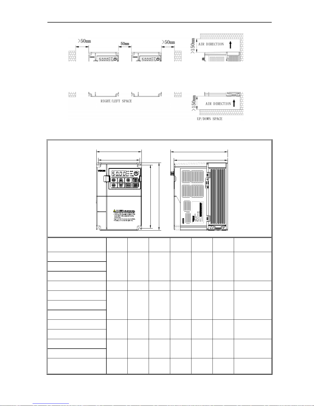
Chart 3-10: Multi AC100 Series Inverters Paratactic Installation Space Requirement
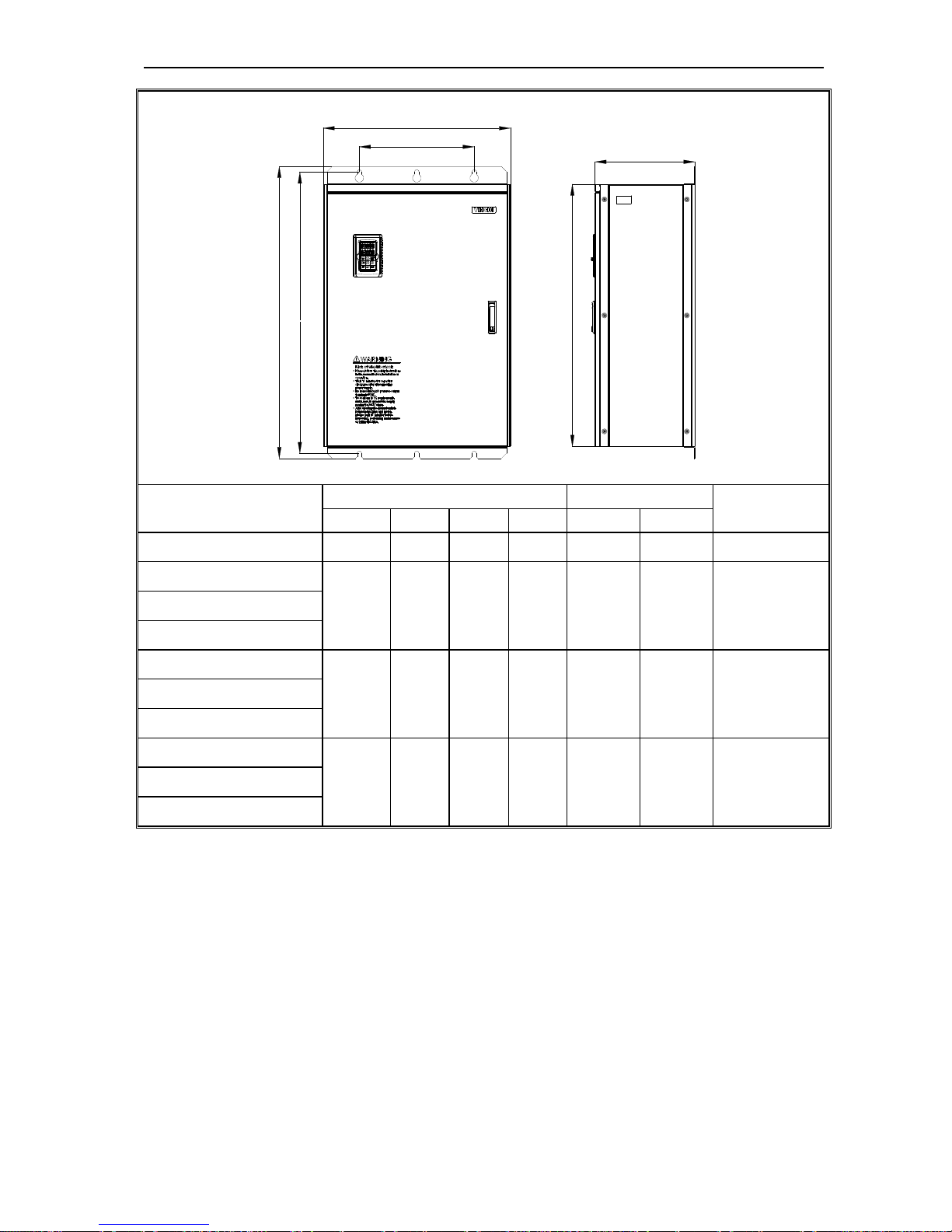
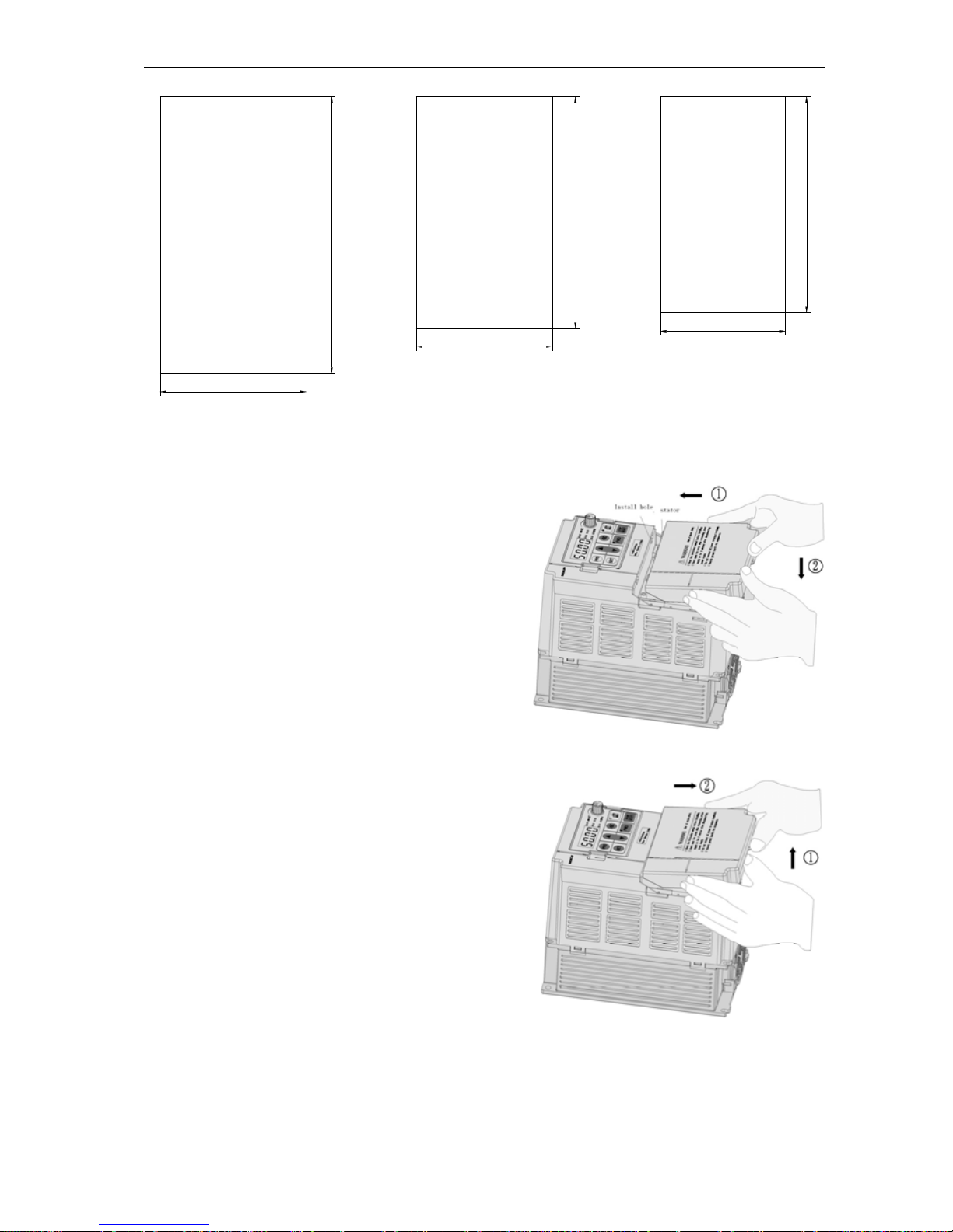
Overall Dimension of Inverter and Keyboard
W1
W
H1
H
D1
D
MODEL W W1 H H1 D D1
INSTALLATION
APERTURE
AC100-S2-R40G
122 112 182 171 154.5 145 ф5 AC100-S2-R75G
AC100-S2-1R5G
AC100-S2-2R2G 159 147.2 246 236 157.5 148 ф5.5
AC100-T3-R75G
122 112 182 171 154.5 145 ф5 AC100-T3-1R5G
AC100-T3-2R2G
AC100-T3-004G
159 147.2 246 236 157.5 148 ф5.5
AC100-T3-5R5G
AC100-T3-7R5G
195 179 291 275 167.5 158 ф7
AC100-T3-011G
AC70-T3-015G/018P
(plastic cover machine)
230 208 330 315 200 190 ф7
AC100 HIGH-PERFORMANCE VC INVERTER MANUAL INSTALLATION AND WIRING
17
AC70-T3-018G/022P
(plastic cover machine)
230 208 330 315 200 190 ф7
AC70-T3-022G/030P
(plastic cover machine)
MODEL
Overall Dimension
Instillation
Position
INSTALLATION
APERTURE
W H D H2 W1 H1
AC100-T3-015G
(steel cover machine)
235 345 200 311 160 331.5 ф7
AC100-T3-018G
(steel cover machine)
AC100-T3-022G
(steel cover machine)
255 410 225 370 180 395 Ф7
AC100-T3-030G
AC100-T3-037G
305 570 260 522 180 550 Ф9 AC100-T3-045G
AC100-T3-055G
AC100-T3-075G
380 620 290 564 240 595 ф11
AC100-T3-090G
AC100-T3-110G
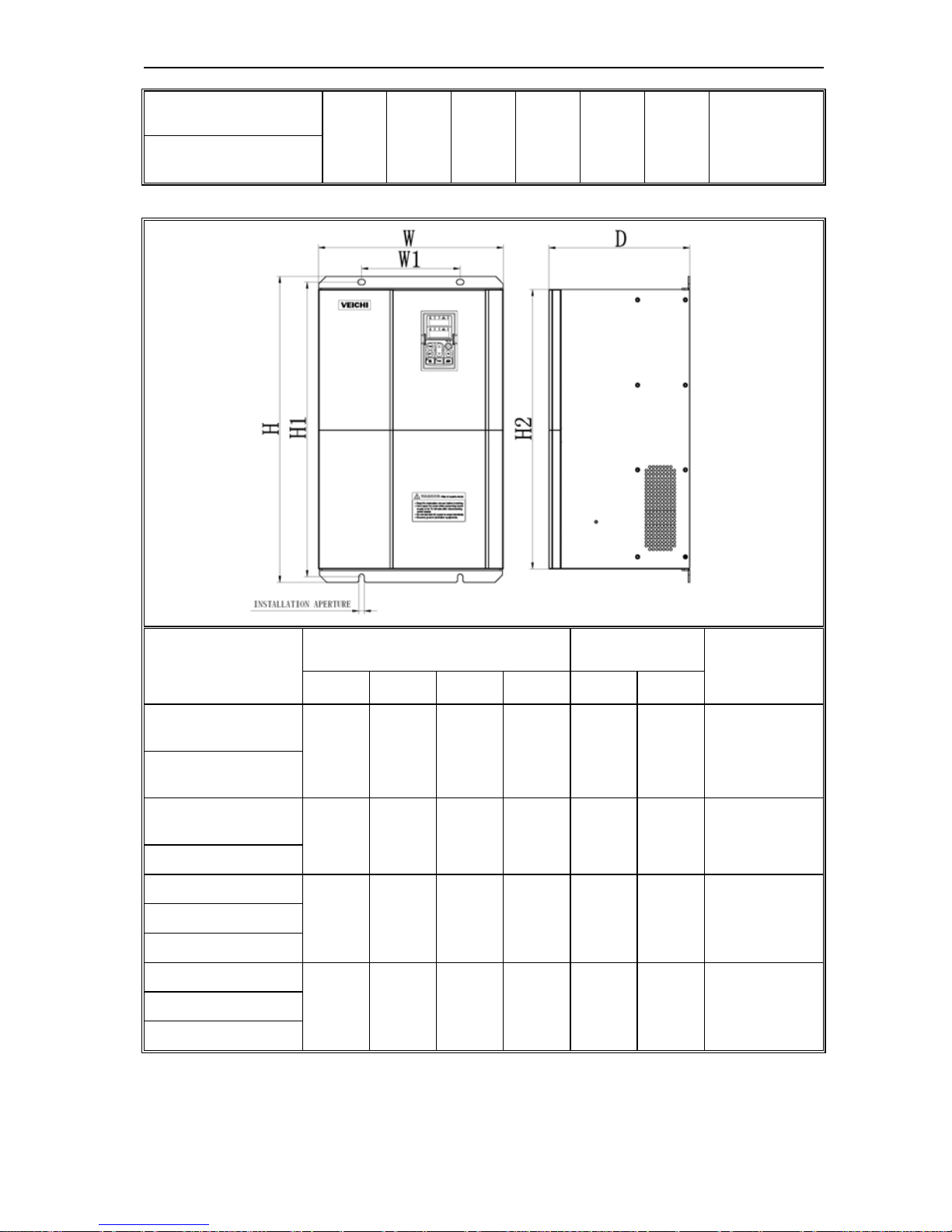
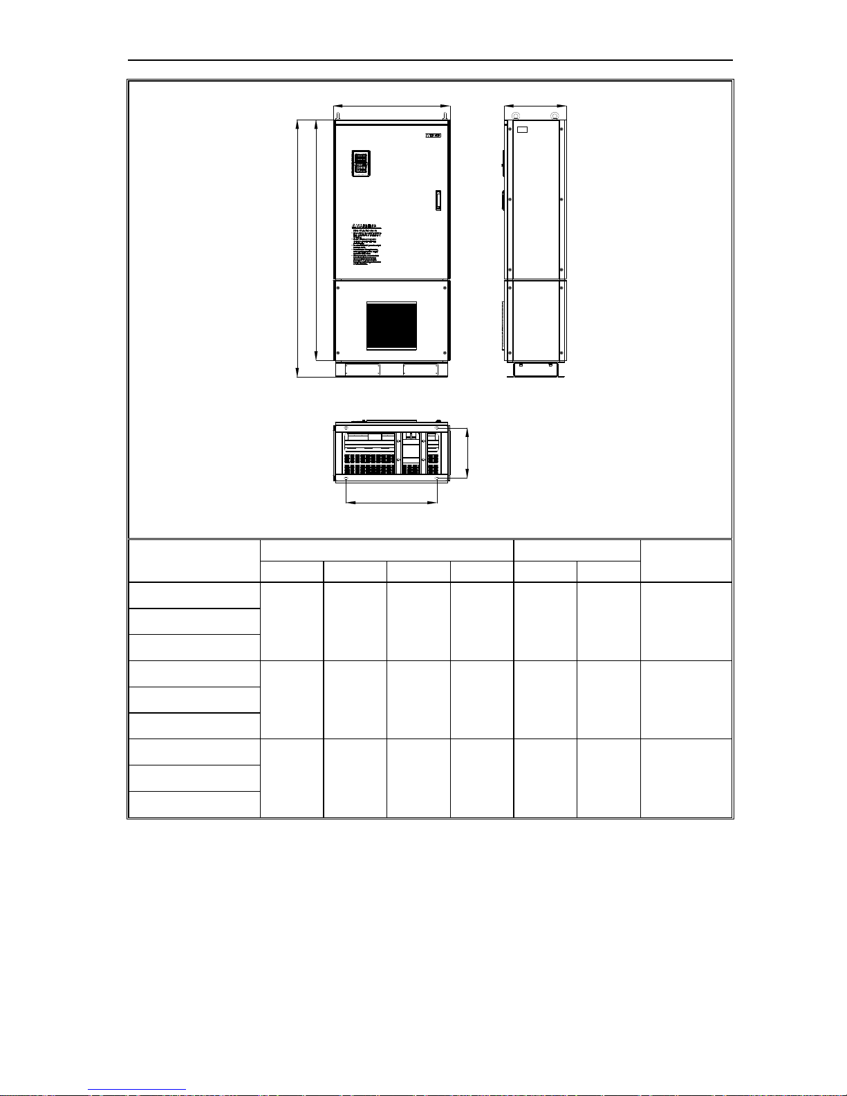
AC100 HIGH-PERFORMANCE VC INVERTER MANUAL INSTALLATION AND WIRING
18
H1
H
H2
D
W1
W
MODEL
Overall Dimension Instillation Position
INSTALLATION
APERTURE
W H D H2 W1 H1
AC100-T3-132G
500 780 340 708 350 755 ф11
AC100-T3-160G
650 1060 400 950 400 1023 ф16 AC100-T3-185G
AC100-T3-200G
AC100-T3-220G
750 1170 400 1050 460 1128 ф18 AC100-T3-250G
AC100-T3-280G
AC100-T3-315G
850 1280 450 1150 550 1236 ф20 AC100-T3-355G
AC100-T3-400G
Notice: No DC Reactor Inside
AC100 HIGH-PERFORMANCE VC INVERTER MANUAL INSTALLATION AND WIRING
19
D1
W1
D
W
H
H1
MODEL
Overall Dimension Instillation Position
INSTALLATION
APERTURE
W H D H1 W1 D1
AC100-T3-160GD
650 1600 400 1500 492 332 ф14 AC100-T3-185GD
AC100-T3-200GD
AC100-T3-220GD
750 1700 400 1600 582 332 ф14 AC100-T3-250GD
AC100-T3-280GD
AC100-T3-315GD
850 1800 450 1700 622 382 ф14 AC100-T3-355GD
AC100-T3-400GD
Notice: DC Reactor Inside
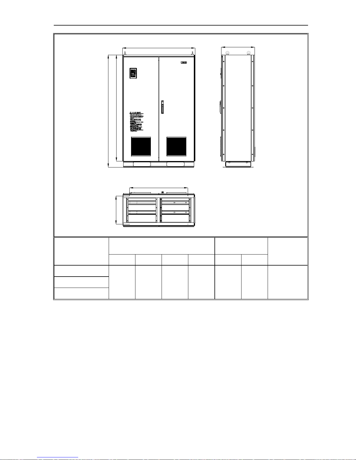
AC100 HIGH-PERFORMANCE VC INVERTER MANUAL INSTALLATION AND WIRING
20
H
H1
D1
W1
D
W
MODEL
Overall Dimension Instillation Position
INSTALLATIO
N APERTURE
W H D H1 W1 D1
AC100-T3-450G
1200 1850 550 1750 960 466 ф14 AC100-T3-500G
AC100-T3-560G
Chart 3-3:AC100 Series Inverter Overall Dimension
AC100 HIGH-PERFORMANCE VC INVERTER MANUAL INSTALLATION AND WIRING
21
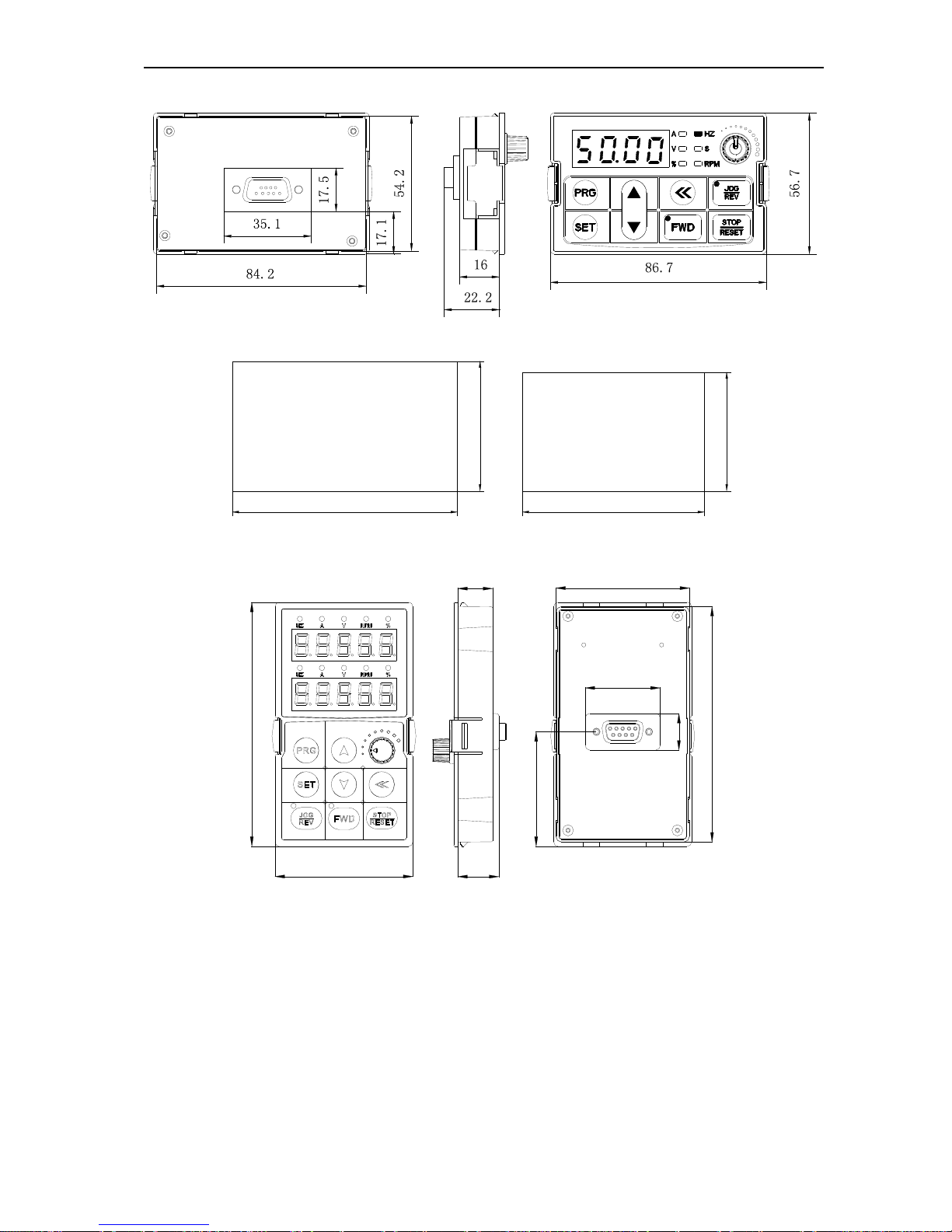
Keyboard Shape and Mouth Dimension
Chart 3-11:AC100 Series Inverter Single Line LED Keyboard Overall Dimension
59,5
104,5
54,5
84,5
Mouth keyboard with box
Mouth keyboard without box
Chart 3-12:AC100 Series Inverter Mouth Dimension for Single Line LED Keyboard Case
114.5
65.5
19.5
16.5
17.1
110.5
63.5
35.6
53.75
Chart 3-13: AC100 Series Inverter Double Line LED Keyboard Overall Dimension
AC100 HIGH-PERFORMANCE VC INVERTER MANUAL INSTALLATION AND WIRING
22
119
70
Mouth keyboard with box
T3-015G/018P
to
T3-132G/160P
111
64
Mouth keyboard without box
142
75
Mouth keyboard with box
T3-160G/185P
to
T3-560G/630P
Chart 3-14: AC100 Series Inverter Mouth Dimension for Double Line LED Keyboard Case
Note: LCD and LED keyboard overall dimensions and the opening dimensions are fully compatible.
Installation and Dismantlement of Tail-hood
Installation: First the tail-hood upwardly inclines around 15
degree and then inserts the top fixed flat into the fixed hole in
the front cover. Then slightly press the tail-hood downward.
When you hear "Ka", it means that the tail-hood is installed
in place.
Chart 3-15:AC100 Series Inverter Tail-hood Installation
Dismantlement: At the tail of the frequency inverter, there’s a
special dismantlement hole design. Put your finger through the
hole, upwardly pull the cover slightly until the buckle between
the tail-hood and the crust tear off, and then remove the
tail-hood.
Chart 3-16:AC100 Series Inverter Tail-hood Dismantlement
AC100 HIGH-PERFORMANCE VC INVERTER MANUAL INSTALLATION AND WIRING
23
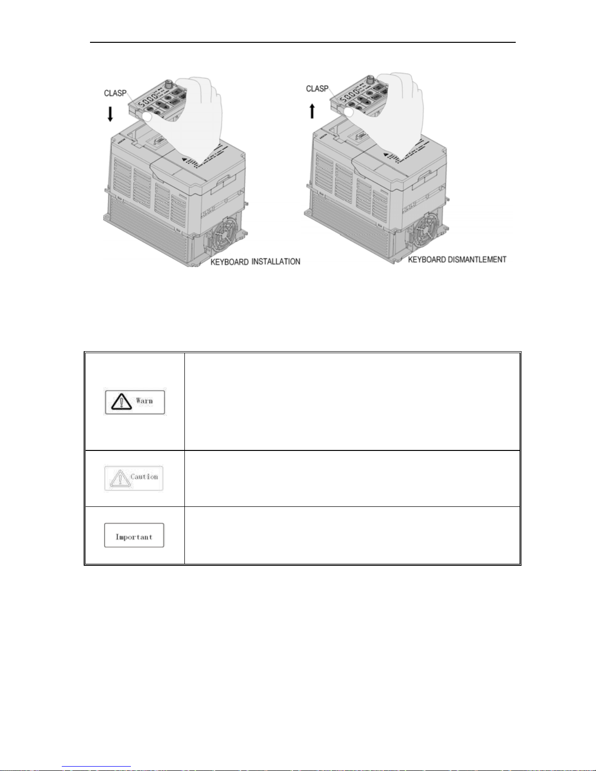
Installation and Dismantlement of keyboard
Chart 3-17:AC100 Series Inverter Keyboard Installation and Dismantlement
3.6 Electrical Installation
To ensure safe, reliable and rational use of this product, please fully understand the safety precautions described in this
manual before using.
Safety Precautions
● Inverter must earth reliably when running. Otherwise there is danger of casualty and
unstable inverter performance.
● To ensure safety running, only trained personnel can do installation and wiring job.
● No operation under power connected state. Otherwise there might be danger of electric
shock even death.
● Please turn off the power of all related equipment, and make sure the main circuit DC
voltage has dropped to a safe level, and wait five minutes before any relevant job.
●The wiring of control cables, power cables and motor connection cables must be isolated
from each other and do not put them in the same cable though or cable racks.
●
The device can only be used as specified by the manufacturer, Please consult Veichi
when using in special case.
● No insulation tests for the inverter or the related cable by HV insulation test equipment.
● If the inverter or the peripheral equipment (filer, reactor and etc) needs insulation test,
firstly 500V meter should be used to test the insulation resistance, which should not be
lower than 4MΩ.
AC100 HIGH-PERFORMANCE VC INVERTER MANUAL INSTALLATION AND WIRING
24
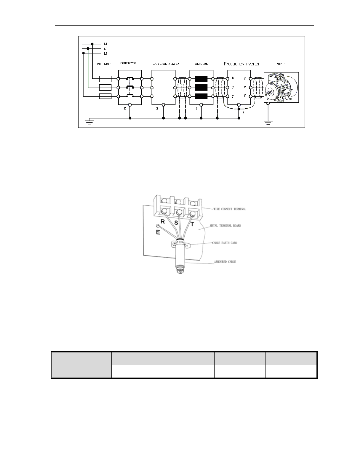
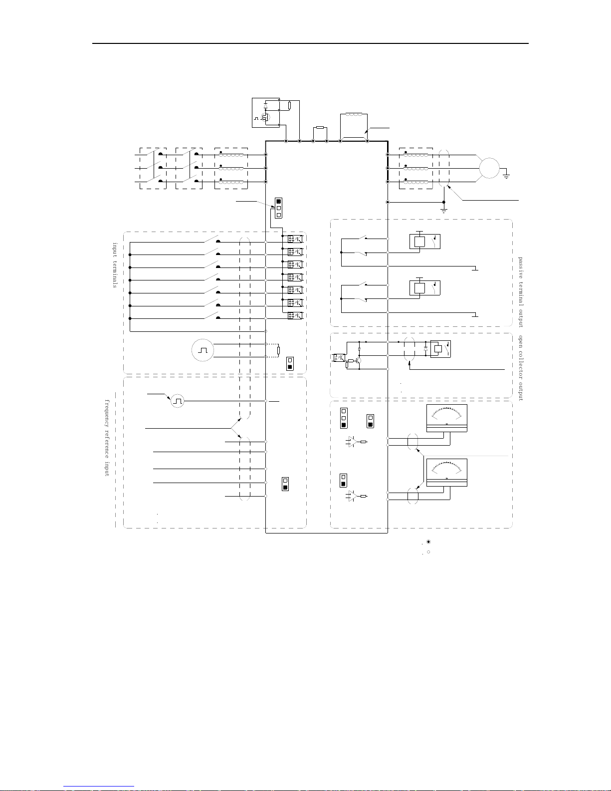
Standard Connection Diagram
● Standard Connection Diagram
notice 2
notice:default settings in bracket
notice 1
TA1
TB1
TC1
+24V
Y
shielded twisted pair cable
_
mA
2
0
10
0
-
+
0
5
1
0
V
_
+
-
GND
A01
V
W
U
M
~
shielded cables
(near inverter groud )
E
(ground resistor low
than 10
Ω
)
W
V
U
output reactor
DC reactor
brake
resistor
short
circuit
P1
+
( )
R
brake module
voltage model analog input
current model analog input
+10V
R
T
S
AC input
AI
GND
AS
VS
shielded twisted pair line)
input pulse
X7
(reversal jog running)
(forward jog running)
(reversal running)
(forward running)
(free stop)
(fault reset)
(none)
COM
X3
X4
X6
X5
X1
X2
PB
( )
+
(-)
inverter
S
T
R
GND
A02
COM
p
a
s
s
i
v
e
t
e
r
m
i
n
a
l
o
u
t
p
u
t
AC220V
AC0V
K3
K4
max output
3A/240VAC
5A/30VDC
1+24Vmax output:DC24V/100mA
A01/A02 used as frequency or
voltage outp ut
,max current
2mA
2VS/AIterminal resistor:75K
Ω
1.+10V terminals max input 50mA
notice:
2Y max output:DC24V/50mA
notice:
2
stand for control circuit terminal
notice:
stand for main circuit terminal
1
shielded twisted pair
cable(near inverter ground)
input reactorconnector
circuit
breaker
(
0~5V
)/(
0~10V
)
(
0~20mA
)/(
4~20mA
)
3AS term in al resistor:250
Ω
notice:
+
( )
notice 4
PUL
X7
PUL
+24V
PLC
COM
current/voltage analog input
J1
J2
J3
K1
K2
K5
K6
TA2
TB2
TC2
AC220V
AC0V
o
p
e
n
c
o
l
l
e
c
t
o
r
o
u
t
p
u
t
A+
B-
RS485 communication
120
Ω
K7
K8
analog output monitor
i
n
p
u
t
t
e
r
m
i
n
a
l
s
f
r
e
q
u
e
n
c
y
r
e
f
e
r
e
n
c
e
i
n
p
u
t
Chart 3-18:AC100 Series Inverter Standard Connection Diagram
Note: 1.When installing DC reactor, make sure to dismantle the short connector between terminal P1 and(+).
2.NPN or PNP transistor signal can be selected as input of multi-function input terminal(X1~X7/PUL).
Inverter built-in power supply (+24V terminal) or external power supply (PLC terminal) can be chosen as
bias voltage. Factory setting ‘+24V’ short connect with ‘PLC’.
3. Analog monitor output is the special output for meters such as frequency meter, current meter and voltage
meter. It can’t be used for control operations such as feedback control.
4. As there are multi pulse styles, please refer to the line connect mode description details.
AC100 HIGH-PERFORMANCE VC INVERTER MANUAL INSTALLATION AND WIRING
25
● Auxiliary Terminal Output Capacity
Terminal Function Definition Max Output
+10V
10V auxiliary power supply output, constitutes loop
with GND.
50mA
A01/A02 Analog monitor output, constitutes loop with GND.
Max output 2mA as frequency,
voltage signal,
+24V
24V auxiliary power supply output, constitutes loop
with COM.
100mA
Y
Collector open circuit output; can set the
action-object by program.
DC24V/50mA
TA1/TB1/TC1
TA2/TB2/TC2
Passive connector output; can set the action-object
by program.
3A/240VAC
5A/30VDC
Chart 3-4:AC100 Series Inverter Auxiliary Terminals Output Capacity
●Connection Function Specification of Switch Terminals
AS
VS
GND
GND
AO2 AO1
X1
X2
AI
+10V
COM
TC1
PLC TA1
A+
+24V
X7/PUL
X4
X3
X5
TB2
X6
TA2
B- Y
TB1
COM
TC2
Switch
Treminal
Selecting
Position
Function Specification
S1
K1 AO1:0~20mA or 4~20mA current output
K2 AO1:0~10V voltage output
S2
K3 AI:0~20mA or 4~20mA input current
K4 AI: 0~10V input voltage
S3
K5 AO2: 0.0~50kHz (J1 on), open collector circuit output
K6 AO2:0.0~50kHz (J1 on), active source output
S4
K7 RS485: connect with 120Ω terminal resistor
K8 RS485:connect without 120Ω terminal resistor
S5
J1 AO2:0.0~50kHz frequency output
J2 AO2:0~20mA or 4~20mA current output
J3 AO2:0~10V voltage output
AC100 HIGH-PERFORMANCE VC INVERTER MANUAL INSTALLATION AND WIRING
26
S6
+24V Short +24V terminal and PLC terminal
PLC PLC terminal receiving external power input, detailed in Drawing 3-22,3-23
COM Short PLC terminal and COM terminal
S7
K9 Disconnect GND terminal and PE discharge loop
K10 Connect GND terminal and PE discharge loop
Chart 3-5:AC100 Series Inverter Switch Terminal Connection Function Specification
Main Circuit Terminals
● Main circuit terminals array and definition
Arrangement sequence of main circuit terminal with 18.5kW or less power(15 ~ 18.5KW for steel cover machine)
(-)
TSR
PB
UWV
(+)
E
Arrangement sequence of main circuit terminal with 15-22KW(15~22KW for plastic cover machine)
Arrangement sequence of main circuit terminal with 22~30KW (standard machine without PB terminal)(22KW for steel
cover machine)
Arrangement sequence of main circuit terminal with 37~110kW
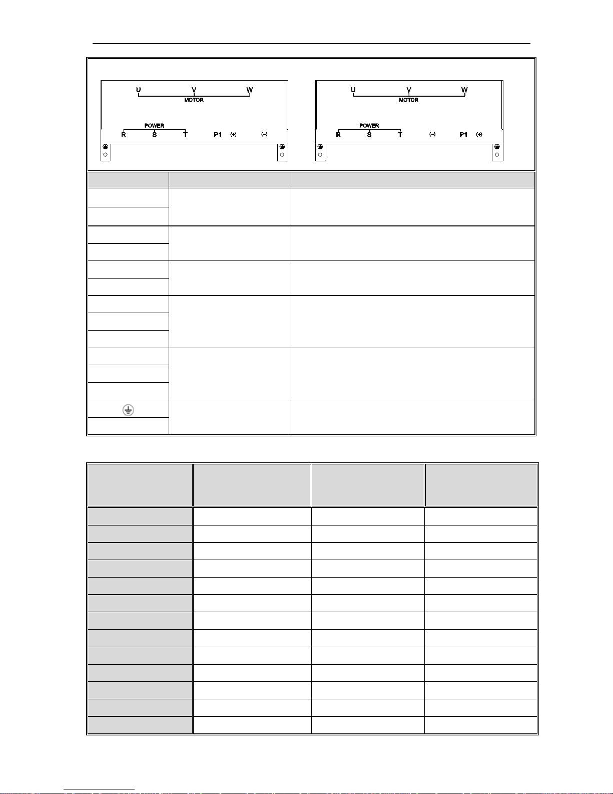
AC100 HIGH-PERFORMANCE VC INVERTER MANUAL INSTALLATION AND WIRING
27
Arrangement sequence of main circuit terminal with 132kW: Arrangement sequence of main circuit termi nal with 160~560kW
Terminal Symbol Name Function Definition
(-)
DC power terminal
DC power output, (-) means DC bus cathode, (+) means DC
bus anode, used for external braking unit.
(+)
(+)
Braking resistance terminal Used for external braking resistance to realize quick stop.
PB
P1
DC reactor terminal Used for external DC reactor.
(+)
R
Inverter input terminal Used to connect 3-phase AC power supply. S
T
U
Inverter output terminal Used to connect the motor. V
W
Earth Earth terminal, earth resistance<10Ω
E
Chart 3-6:AC100 Series Inverter Main Circuit Terminals Array and Definition
● 3-phase 380V Machine Main Circuit Wiring
Model
Main Circuit Terminals
Screw Specifications
Suggested Fixed Moment
(N·m)
Suggested Copper-core
Cable Specification mm
2
(AWG)
AC100-T3-R75G M4 1.2~1.5 1.5mm2(14)
AC100-T3-1R5G M4 1.2~1.5 2.5mm2(12)
AC100-T3-2R2G M4 1.2~1.5 2.5mm2(12)
AC100-T3-004G M4 1.2~1.5 4mm2(10)
AC100-T3-5R5G M4 1.2~1.5 6mm2(9)
AC100-T3-7R5G M5 2~2.5 6mm2(9)
AC100-T3-011G M5 2~2.5 10mm2(7)
AC100-T3-015G M6 4~6 10mm2(7)
AC100-T3-018G M6 4~6 16mm2(5)
AC100-T3-022G M8 8~10 16mm2(5)
AC100-T3-030G M8 8~10 25mm2(3)
AC100-T3-037G M8 8~10 25mm2(3)
AC100-T3-045G M8 8~10 35mm2(2)

AC100 HIGH-PERFORMANCE VC INVERTER MANUAL INSTALLATION AND WIRING
28
AC100-T3-055G M10 11~13 35mm2(2)
AC100-T3-075G M10 11~13 50mm2(1)
AC100-T3-090G M10 11~13 50mm2(1/0)
AC100-T3-110G M10 11~13 70mm2(2/0)
AC100-T3-132G M10 11~13 95mm2(3/0)
AC100-T3-160G M12 14~16 95mm2(4/0)
AC100-T3-185G M12 14~16 120mm2
AC100-T3-200G M12 14~16 150mm2
AC100-T3-220G M12 14~16 150mm2
AC100-T3-250G M12 14~16 185mm2
AC100-T3-280G M12 14~16 185mm2
AC100-T3-315G M16 20~23 240mm2
AC100-T3-355G M16 20~23 240mm2
AC100-T3-400G M16 20~23 300mm2
AC100-T3-450G M16 20~23 400mm2
AC100-T3-500G M16 20~23 400mm2
AC100-T3-560G M16 20~23 500mm2
Note: Here we suggest using copper joins for mains electric connectors for machine over 185KW. Please refer to
diagram above for the cut section area.
Chart 3-7: Suggested Cable Diameter and Fixed Moment of 3-phase 380V Machine Main Circuit
● Single-phase 220V Machine Main Circuit Wiring
Model
Main Circuit Terminals
Screw Specifications
Suggested Fixed
Moment (N·m)
Suggested Copper-core
Cable Specification mm
2
(AWG)
AC100-S2-R40G M4 1.2~1.5 1.5mm2(14)
AC100-S2-R75G M4 1.2~1.5 2.5mm2(12)
AC100-S2-1R5G M4 1.2~1.5 2.5mm2(12)
AC100-S2-2R2G M4 1.2~1.5 4mm2(10)
Chart 3-8: Suggested Cable Diameter and Fixed Moment Single-phase 220V Machine Main Circuit
● Suggested Main Circuit Components Specification
Model
Contactor
Specification
Breaker
Specification
DC Reactor Input Filter Output Filter
AC100-T3-R75G 10A 10A ------ NFI-005 NFO-010
AC100-T3-1R5G 10A 10A ------ NFI-005 NFO-010
AC100-T3-2R2G 16A 15A ------ NFI-010 NFO-010
AC100-T3-004G 16A 20A ------ NFI-010 NFO-010
AC100-T3-5R5G 25A 20A ------ NFI-020 NFO-020
AC100-T3-7R5G 25A 30A ------ NFI-020 NFO-020
AC100-T3-011G 32A 40A ------ NFI-036 NFO-036
AC100-T3-015G 40A 50A ------ NFI-036 NFO-036

AC100 HIGH-PERFORMANCE VC INVERTER MANUAL INSTALLATION AND WIRING
29
AC100-T3-018G 50A 60A ------ NFI-050 NFO-050
AC100-T3-022G 50A 75A DCL-50 NFI-050 NFO-050
AC100-T3-030G 63A 100A DCL-80 NFI-080 NFO-080
AC100-T3-037G 80A 125A DCL-100 NFI-100 NFO-100
AC100-T3-045G 100A 150A DCL-110 NFI-100 NFO-100
AC100-T3-055G 125A 175A DCL-125 NFI-150 NFO-150
AC100-T3-075G 160A 200A DCL-150 NFI-150 NFO-150
AC100-T3-090G 220A 250A DCL-200 NFI-200 NFO-300
AC100-T3-110G 220A 300A DCL-200 NFI-200 NFO-300
AC100-T3-132G 250A 400A DCL-300 NFI-300 NFO-300
AC100-T3-160G 300A 500A DCL-300 NFI-300 NFO-300
AC100-T3-185G 400A 600A DCL-400 NFI-400 NFO-400
AC100-T3-200G 400A 700A DCL-400 NFI-400 NFO-400
AC100-T3-220G 630A 800A DCL-500 NFI-600 NFO-600
AC100-T3-250G 630A 1000A DCL-600 NFI-600 NFO-600
AC100-T3-280G 630A 1200A DCL-600 NFI-600 NFO-600
AC100-T3-315G 630A 1200A DCL-800 ------ -----AC100-T3-355G 800A 1400A DCL-800 ------ -----AC100-T3-400G 1000A 1600A DCL-1000 ------ -----AC100-T3-450G 1000A 2000A DCL-1000 ------ -----AC100-T3-500G 1000A 2000A DCL-1200 ------ -----AC100-T3-560G ------ 2000A DCL-1200 ------ ------
Note: For specification details and circuit mode of DC reactor, input filter, output filter and other components, please
refer to Chapter 7 “Peripheral Equipments and Options”.
Chart 3-9: Suggested Mains Fittings for 3-phase 380V Machine
Control Loop Te rminals
● Control Loop Terminals Array:
AS
VS GND
GND
AO2 AO1
X1
X2
AI
+10V
COM
TC1
PLC TA1
A+ +24V
X7/PUL
X4
X3
X5
TB2
X6
TA2
B- Y
TB1
COM
TC2

AC100 HIGH-PERFORMANCE VC INVERTER MANUAL INSTALLATION AND WIRING
30
Category
Terminal Symbol Name Function Definition
Power
+10V-GND +10V power supply
Supply +10V power, max output current: 50
mA ,usually used for potentiometer supply,
resistance of potentiometer range: 1KΩ~5KΩ
+24V-COM +24V power supply
Supply +24V power, usually used for digital
input/output terminals and external sensors, max
output current:100 mA
PLC Public terminal
Connect with +24V terminal by factory default.
When using external signal to drive X1-X7/PUL,PLC
must be connected with external power, and be
disconnected with +24V terminal (detailed in Drawing
3-22, 3-23)
Analog
input
AS-GND Current analog input
1.input current range: DC 0mA~20mA
2.input impedance: 500Ω
VS-GND Voltage analog input
1.input voltage range: DC 0V~10V
2.input impedance: 75 KΩ
AI-GND
Voltage or current analog
input
1.input range: DC 0V~10V/0mA~20mA,decided
by switch S2(detailed in Drawing 3-5)
2.voltage input impedance: 75 KΩ
3.current input impedance: 500Ω
Chart 3-10:AC100 Series Inverter Control Loop Terminals Array and Definition
● Control Loop Terminal Wiring Specification
Terminal
Bolt Specification
(mm)
Fixed Moment
(N·m)
Cable specification
(mm2)
Cable Type
A+ B- M2.5 0.4~0.6 0.75
Twisted-pair shielded
cable
+10V GND A01 A02 AS
VS AI
M2.5 0.4~0.6 0.75
Twisted-pair shielded
cable
+24V COM Y TA 1 TB1
TC1 TA2 TB2 TC2 PLC
X1 X2 X3 X4 X5 X6
X7/PUL
M2.5 0.4~0.6 0.75 Shielded cable
Chart 3-11:Control Loop Terminal Wiring Specification
Braking Unit (Braking Resistance) Connection
● Brake resistance wiring of machine with 18.5KW or less power(15KW-18.5KW for steel cover machine)
(-)
(+)
PB
R
ST
U
V
WE
Brakeing
resistor
Fig 3-19: AC100 Series Frequency Inverter Brake resistance wiring of machine with 18.5KW or less power

AC100 HIGH-PERFORMANCE VC INVERTER MANUAL INSTALLATION AND WIRING
31
● Brake resistance wiring of machine with 15-22KW(for plastic cover machine)
Brakeing
resistor
Fig 3-20: AC100 Series Frequen cy Inverter Brake resistance wiring of machine with 15-22KW(for plastic cover machine)
● Brake resistance wiring of machine with 22KW and 30KW(built-in brake is optional)(22KW for steel cover machine)
TSR
PB
UWV
POWER INPUT MOTOR OUTPUT
Brakeing
resistor
(-)(+)
Fig 3-21: AC100 Series Frequency Inverter Brake resistance wiring of machine with 22KW and 30KW(built-in
brake is optional)(22KW for steel cover machine)
● Brake resistance wiring of machine with 37KW or above
TSR
PB
UWV
POWER INPUT MOTOR OUTPUT
Dynamic Brake Unit
POWER
ACTIVE
-
++
PB
Brakeing
resistor
(-)(+)
Fig 3-22: AC100 Series Frequency Inverter Brake resistance wiring of machine with 37KW or above
●
Suggested braking resistance specification parameters
The braking resistance value and resistance power in the chart below are in accordance with the general inertia of the
load and intermittent braking mode, In large inertia and long braking frequent occasions, adjust resistance value and
power according to the inverter specification and the rated parameter of braking unit. If any problem, please consult
customer service department of Shenzhen Veichi Electric Co., Ltd.

AC100 HIGH-PERFORMANCE VC INVERTER MANUAL INSTALLATION AND WIRING
32
Three-phase 380V
Motor power(kW) Resistance value(Ω) Resistance Power(kW) Braking Moment (%)
0.75 kW 750Ω 150W 100%
1.5 kW 400Ω 300W 100%
2.2 kW 250Ω 400W 100%
4.0 kW 150Ω 500W 100%
5.5 kW 100Ω 600W 100%
7.5 kW 75Ω 780W 100%
11 kW 50 Ω 1,200W 100%
15 kW 40Ω 1,500W 100%
18.5 kW 32Ω 2,000W 100%
22 kW 28Ω 2,200W 100%
30 kW 24Ω 3,000W 100%
37 kW 20Ω 3,700W 100%
45 kW 16Ω 4,500W 100%
55 kW 13Ω 5,500W 100%
75 kW 9Ω 7,500W 100%
90 kW 6.8Ω 9,300W 100%
110 kW 6.2Ω 11,000W 100%
132 kW 4.7Ω 13,000W 100%
160 kW 3.9Ω 15,000W 100%
185 kW 3.3Ω 17,000W 100%
200 kW 3Ω 18,500W 100%
220 kW 2.7Ω 20,000W 100%
250 kW 2.4Ω 22,500W 100%
280 kW 2Ω 25,500W 100%
315 kW 1.8Ω 30,000W 100%
355 kW 1.5Ω 33,000W 100%
400 kW 1.2Ω 42,000W 100%
450 kW 1.2Ω 42,000W 100%
500 kW 1Ω 42,000W 100%
560 kW 1Ω 50,000W 100%
Single-phase 220V
Motor power(kW) Resistance value(Ω) Resistance power(kW) Braking moment (%)
0.4 kW 400Ω 100W 100%

AC100 HIGH-PERFORMANCE VC INVERTER MANUAL INSTALLATION AND WIRING
33
0.75 kW 200Ω 120W 100%
1.5 kW 100Ω 300W 100%
2.2 kW 75 Ω 300W 100%
Chart 3-12: Suggested Braking Resistance Specification Parameters of AC100 Series Inverter
● Build-in braking unit max braking performance
Braking unit of AC100 series product with low power can be selected according to the suggested braking resistance
specification parameters in chart 3-11. In large inertia or long time frequent braking occasion, the moment should be
increased. The max braking power is stated in the following chart and the range of which can’t be exceeded in use.
Otherwise the equipment may be damaged. If any problem, please consult customer service department of Shenzhen
Veichi Electric Co., Ltd.
Three-phase380V
Inverter Model Motor Power Max Braking Current Min Resistance
AC100-T3-R75G 0.75 kW 3.5A 200Ω
AC100-T3-1R5G 1.5 kW 3.5A 200Ω
AC100-T3-2R2G 2.2 kW 7A 100Ω
AC100-T3-004G 4 kW 10A 75Ω
AC100-T3-5R5G 5.5 KW 10A 75Ω
AC100-T3-7R5G 7.5 kW 14A 50Ω
AC100-T3-011G 11 kW 17A 40Ω
AC100-T3-015G 15 kW 23A 30Ω
AC100-T3-018G 18.5 kW 28A 25Ω
Single-phase 220V
Inverter Model Motor Power Max Braking Current Min Resistance
AC100-S2-R40G 0.4 kW 3.8A 100Ω
AC100-S2-R75G 0.75 kW 3.8A 100Ω
AC100-S2-1R5G 1.5 kW 6.5A 60Ω
AC100-S2-2R2G 2.2 kW 10.5A 40Ω
Chart 3-13:AC100 Series Inverter Build-in Braking Unit Max Braking Power

AC100 HIGH-PERFORMANCE VC INVERTER MANUAL INSTALLATION AND WIRING
34
Multi-functional Contact Input Connection
● NPN transistor connection mode
Use inner 24V power
+24V
PLC
X1
X2
X4
X3
X7
X6
X5
COM
shielded cable
E
(factory short connect)
E
COM
X5
X6
X7
X3
X4
X2
X1
PLC
+24V
Use innner 24V power
exterior
control
signal
exterior
control
signal
shielded cable
Note:Disconnect '+24V'with'PLC' when using exterior power
exterior 24V power
+
-
+24V
PLC
COM
+24V
PLC
COM
PUL PUL
inverter inverter
Chart 3-23: NPN Transistor Digital Input Signal Connection Mode
● PNP transistor connection mode
-
+
use exterior 24 power
E
X5
X6
X7
X3
X4
X2
X1
PLC
+24V
Use inner 24V power
COM
Use inner 24V power
shielded cable
exterior
control
signal
+24V
PLC
COM
PUL
inverter
+24V
PLC
COM
exterior
control
signal
shielded cable
E
X5
X6
X7
X3
X4
X2
X1
PLC
+24V
COM
PUL
inverter
Chart 3-24: PNP Transistor Digital Input Signal Connection Mode
Digital output signal connection
shielded twisted
pair cable
COM
winding
E
Y1
+24V
COM
inverter
exterior 24V power
- +
inverter
shield twisted pair cable
winding
COM
Y1
+24V
E
COM
Chart 3-25:AC100 Series Inverter Digital Output Signal Connection Mode

AC100 HIGH-PERFORMANCE VC INVERTER MANUAL INSTALLATION AND WIRING
35
Analog Output Signal Connection
shielded twisted pair cable
shielded twisted pair cable
GND
E
AO1
shielded twisted pair cable
-
+
_
V
1
0
5
0
AO2 terminal use as 0~10V output indicator
inverter
AO1 terminal use as 0~10V output indicator
0
5
1
0
V
_
+
-
AO1terminal use as 0~20mA output indicator
0
10
2
0
mA
_
AO2 terminal use as 0.2~50kHz active source pulse output
kHz
5
0
25
0
-
+
+
-
shielded twisted pair cable
AO2 terminal use as 0~20mA output indicator
0
10
2
0
mA
_
-
+
shielded twisted pair cable
K1
K2
K1
K2
J1
J2
J3
J1
J2
J3
shielded twisted pair cable
AO2 terminal use as 0.2~50kHz open collector circuit pulse output
kHz
5
0
25
0
+
-
J1
J2
J3
K5
K6
bias resistor
-
+
exterior power
inverter
inverter inverter
GND
E
AO2
GND
E
AO2
GND
E
AO2
GND
E
AO2
GND
E
AO2
inverter
inverter
J1
J2
J3
K5
K6
Chart 3-26:AC100 Series Inverter Analog Output Signal Connection Mode
Connection of Pulse Input Signal
connection of passive source pulse signal input
connection of active source pulse signal input
E
COM
PUL
COM
pulse signal source
shielded twisted pair source
inverter
+24V
PLC
COM
X7
PUL
shielded twisted pair source
pulse signal source
PUL
COM
E
COM
X7
PUL
inverter
+24V
PLC
COM
Chart 3-27: Pulse Input Signal Connection Mode of AC100 Series Inverter

AC100 HIGH-PERFORMANCE VC INVERTER MANUAL INSTALLATION AND WIRING
36
Standby Control System
Frequency inverter is composed of semiconductor, passive electronic component and driving part. And these devices
have working life even under normal working conditions and these devices may also have characteristic variation or
failure. These characteristics change or failure would inevitably lead to failure of the product. Setting standby control
system when using the inverter is highly recommended to prevent lost production caused by product failure.
Figure 3-28 is the standby control system for manual switch converting to direct driving motor of power supply when
inverter fails. Standby control systems such as power supply Y/Δ step-down start way driving motor, power supply
self-coupling reduction voltage start mode driving motor, power supply soft start mode driving motor or standby inverter
system can be chose to use according to the actual needs and environment.
Figure 3-28: Standby Control System of Power Supply Direct Driving Mode

AC100 HIGH-PERFORMANCE VC INVERTER MANUAL BASIC OPERATION AND TRIAL RUN
37
Chapter 4 Basic Operation and Trial Run
4.1 Safety Precautions
● No wiring while power supply is connected. Otherwise there is danger of electric
shock.
● No operation when the cover is open. Otherwise, there is danger of electric shock.
● Please ensure reliable earth. Otherwise, there is danger of electric shock and fire.
● Before wiring please cut power supply of all related equipments and ensure main
DC voltage in safe range. And please do operation after 5 mins.
● Only trained personnel is allowed to operate this product.
● Please do not dismantle the inverter cover when it is electrified. Otherwise, there is
danger of electric shock.
● Please do not touch the printed circuit board of the inverter while it is electrified.
Otherwise, there is danger of electric shock.
● Please ensure reliable mains cable connection. If the mains cable is loose, there is
danger of fire caused by joint overheat.
● Before electrifying, please check the power voltage again. Wrong power voltage can
cause fault or damage of the inverter, or even fire.
● Please do not install inverter on flammable material or attach flammable material to
the inverter. Before electrifying, please clear the surroundings.
Important
● When operating, please follow the ESD regulations. Otherwise, the inverter may be
damaged.
● Please don’t cut the power directly when the inverter drives the motor running.
The power can’t be cut until the motor totally stop. Otherwise, the inverter may be
damaged.
● Please don’t cut or connect motor when the inverter drives the motor running.
The motor can’t be cut or connect until the inverter output is 0. Otherwise, the
inverter may be damaged.
● Control cable should be twisted-pair shielded cable. The barrier should be
connected to the inverter earth terminal reliably to prevent the inverter from
abnormal working.
● Unprofessional personnel can’t do operation like installing, wiring, debugging or
maintenance.
● Changing, dismantlement or maintenance without permission may cause inverter
damage, which is not in our quality assurance range.

AC100 HIGH-PERFORMANCE VC INVERTER MANUAL BASIC OPERATION AND TRIAL RUN
38
4.2 Keyboard Layout and Function Specification
● Keyboard Appearance
● Key Function
Key Name Function
Menu key
Enter function menu when standby or running. Press this key to return
when modifying parameter. Press for 1 sec to enter condition monitoring
interface when in standby or running condition.
Confirm/modify
key
Press to modify parameter when in menu interface. Press again to
confirm after modifying. Press to change LED monitoring items at down
time when in standby or running condition.
Up/down key
Select parameter group in menu interface. Modify parameter in modifying
interface. Modify given frequency, PID, given torque or magnetic powder
clutch given torque when at standby or condition monitoring state (When
given frequency, PID, given torque or magnetic powder clutch given
torque are set by keyboard, please set [F4.04])
Shift key
Select digit of function number modified by up/down key; Select
parameter digits modified by up/down key.
Forward run key
When run/stop is controlled by keyboard, press this key, the inverter
forwardly rotate and the indicator is always on. When reverse, the
indicator sparks.
Jog/reverse key
This key function can be defined by parameter [F4.02]. Press it, the
machine reverses and indicator is off if this key is defined as REVERSE;
the machine jogs and indicator is on if this key is defined as JOG.
Stop/reset key
The machine stops if press it while run/stop is controlled by keyboard. Its
efficiency range is defined via function no [F4.03]. Inverter resets if press
it in fault state (the machine would not reset if the fault is not solved).
Keyboard
potentiometer
Can be used as input channel for given frequency, upper frequency limit,
given torque, given PID or PID feedback setting.

AC100 HIGH-PERFORMANCE VC INVERTER MANUAL BASIC OPERATION AND TRIAL RUN
39
● Indicator light meanings
Name State Meaning
Unit Indicator
Light
Hz Spark Digital display given frequency.
Hz On Digital display output frequency.
A On Digital display actual output current.
V On Digital display input voltage.
V Spark Digital display output voltage.
S On Time unit is second.
S Spark Time unit is ms, min, or h.
RPM On Digital display motor speed.
% Spark Digital display given PID.
% On Digital display PID feedback.
State
Indicator Light
FWD On Inverter is forwardly rotating.
FWD Spark Inverter is reversely rotating.
FWD Off Inverter stops.
Function
indicator light
REV/JOG On Jog.
REV/JOG Off Reverse.
Chart 4-1: Indicator Light Meanings
● Number and Character Chart
Chart 4-2:Number and Character Chart

AC100 HIGH-PERFORMANCE VC INVERTER MANUAL BASIC OPERATION AND TRIAL RUN
40
●LCD Keyboard Function Meaning
Icon Meaning
Inverter at stop state
Stand for forward running state
Stand for reverse running state
Stand for JOG running state
Auxiliary sign Of reverse running state
Remind to press“ ”button
Remind to press “ ”button
Cursor shift up
Cursor shift down
sparkling means fault state
Reminder of what the arrow points to
Terminal off
Terminal on
Two kinds of relay output: one is open while the other is close.
● Basic LED Operation
It displays frequency at 50.00Hz when stop. Here F0.09=100.00 setting is an example to explain the basic LED
operation.
Chart 4-1: Basic LED Operation

AC100 HIGH-PERFORMANCE VC INVERTER MANUAL BASIC OPERATION AND TRIAL RUN
41
4.3 Basic Operation
● Parameter Initialization
Set F0.19=1, and the parameter initialization is completed. Operation details as follows:
Chart 4-2: Parameter Initialization
●Control Mode Selection of Motor 1
Here we set F0.00=0(AM VC without PG)as an example to introduce.
Chart 4-3: Control Mode Selection of Motor 1
● Start-up Mode Selections
Three start-up modes: 0: direct start-up, 1: braking firstly, then start by start-up frequency, 2: speed track and
start-up. Here we set F1.00=2(speed track and start-up) as an example:
Chart 4-4: Start-up Mode Selections
● Motor Parameter Setting
Set[F5.02](motor rated power),[F5.03](motor rated frequency),[F5.04](motor rated speed), [F5.05]
(motor rated voltage) according to the motor nameplate. Other parameter setting can be obtained by inverter
self-study.
Please refer to the following operation mode chart:

AC100 HIGH-PERFORMANCE VC INVERTER MANUAL BASIC OPERATION AND TRIAL RUN
42
Chart 4-5: Motor Parameter Setting
● Parameter Copy Function Selection
Set F4.05=1, send inverter parameter to keyboard and save:
Chart 4-6: Send Inverter Parameter to Keyboard and Save
Set F4.05=2, send keyboard parameter to inverter:
Chart 4-7: Send Keyboard Parameter to Inverter and Save

AC100 HIGH-PERFORMANCE VC INVERTER MANUAL BASIC OPERATION AND TRIAL RUN
43
● Run Monitoring Setting
Chart 4-8: Run Monitoring Setting
4.4 LCD Keyboard Operation Instructions
● Monitoring Selection Setting Steps
Set of monitoring parameter at stop state as an example. Operations detailed in Chat 4-9. Set keyboard first-line
displays when inverter stops under function parameter F4.11.Factory seting includes four-group parameters
such as input frequency, output frequency, output current and input voltage. Press to change display
content when inverter stops. Press to change displays of uplink monitoring parameter group.
Chart 4-9:Display Change of Uplink Monitoring Parameter Group
● Operation Process of Fault Display
Operation of rectifier bridge overheat fault display as an example, details in Chart 4-10. When keyboard
displays fault, please press to check fault reasons, and press to return back. Press and
to check other fault reasons. Press to reset fault in whole operation.

AC100 HIGH-PERFORMANCE VC INVERTER MANUAL BASIC OPERATION AND TRIAL RUN
44
Chart 4-10:Rectifier Bridge Fault Display
● Operations of Third-level Menu
(1)Operation process of changing lines: Operation of parameter initialization under function code of F0.19 as
an example; set F0.19=1, and the parameter initialization is completed. Details in Chart 4-11.
Chart 4-11:Operations Process of Changing Lines
(2)Operation process of data modifying: Setting of main channel gain under function code of F0.04 as an
example; set F0.04=2.000%. Details in Chart 4-12.

AC100 HIGH-PERFORMANCE VC INVERTER MANUAL BASIC OPERATION AND TRIAL RUN
45
Chart 4-12:Operation Process of Data Modifying
(3)Operation process of groups: Setting carrier frequency characteristic under function code of F0.08. Set ‘1.
Related to output frequency’ in group 2, Details in Chart 4-13.
Chart 4-13:Operation Process of Groups

AC100 HIGH-PERFORMANCE VC INVERTER MANUAL BASIC OPERATION AND TRIAL RUN
46
● Operation Process of Parameters Copy
Operation process of parameters copy in Chart 4-14; download process in Chart 4-15.
Chart 4-14:Operations of Parameter Copy
Chart 4-19:Operations of Parameter Download

AC100 HIGH-PERFORMANCE VC INVERTER MANUAL BASIC OPERATION AND TRIAL RUN
47
● Operation Process of Motor Parameter Self-tuning
Operations of rotary type self-tuning in Chart 4-16; Static type self-tuning in Chart 4-17.
Chart 4-16:Operations of Rotary Type Self-tuning
Chart 4-17:Operations of Static Type Self-tuning

AC100 HIGH-PERFORMANCE VC INVERTER MANUAL BASIC OPERATION AND TRIAL RUN
48
4.5 Trial run
● Frequency Giving Process
f1
-
f2
=
3
=
1
1
=
1
2
C
h
a
r
t 4
-
1
8
:
F
r
e
q
u
e
n
c
y
G
iv
in
g
P
r
o
c
e
s
s
=
6
=
5
=
4
=
2
=
1
=
0
fr
e
q
u
e
n
c
y
g
iv
e
n
c
h
a
n
n
e
l c
a
lc
u
la
tio
n
s
y
n
th
e
s
iz
e
F
0
.0
4
fr
e
q
u
e
n
c
y
g
iv
in
g
m
a
in
c
h
a
n
n
e
l
F
0
.0
3
K
=
2
=
1
=
0
=
3
=
4
=
5
=
1
0
=
9
=
6
=
7
=
8
=
3
=
0
=
1
=
2
K
F
0
.0
5
fr
e
q
u
e
n
c
y
g
iv
in
g
a
u
x
ilia
r
y
c
h
a
n
n
e
l
F
0
.0
6
=
6
=
5
=
4
m
in
{
f1
.f2
}
f1
*
f2
f1
+
f2
m
a
x
{
f1
.f2
}
f
2
f1
m
a
in
g
iv
in
g
f1
a
u
x
ilia
r
y
f2
F
0
.0
7
f
≤
f3
f>
f3
f
f
f3
K
e
y
b
o
a
r
d
n
u
m
b
e
r
g
iv
in
g
P
o
te
n
tio
m
e
te
r
g
iv
in
g
A
n
a
lo
g
A
I g
iv
in
g
A
n
a
lo
g
A
S
g
iv
in
g
T
e
r
m
in
a
l P
U
L
g
iv
in
g
R
S
4
8
5
c
o
m
m
u
n
ic
a
tio
n
g
iv
in
g
U
P
/D
W
c
o
n
tr
o
l
P
ID
c
o
n
tr
o
l
P
L
C
c
o
n
tr
o
l
O
p
tio
n
a
l c
a
r
d
T
e
r
m
in
a
l s
w
itc
h
K
e
y
b
o
a
r
d
n
u
m
b
e
r
g
iv
in
g
P
o
te
n
tio
m
e
te
r
g
iv
in
g
T
e
r
m
in
a
l V
S
1
g
iv
in
g
A
n
a
lo
g
V
S
g
iv
in
g
A
n
a
lo
g
A
S
g
iv
in
g
T
e
r
m
in
a
l P
U
L
g
iv
in
g
R
S
4
8
5
c
o
m
m
u
n
ic
a
tio
n
g
iv
in
g
m
a
in
c
h
a
n
n
e
l g
a
in
a
u
x
ilia
r
y
c
h
a
n
n
e
l g
a
in
u
p
p
e
r
-
lim
it F
0
.1
1
o
u
tp
u
t fr
e
q
u
e
n
c
y
o
u
tp
u
t fr
e
q
u
e
n
c
y
V
S
3
e
x
te
n
s
io
n
T
e
r
m
in
a
l V
S
2
g
iv
in
g

AC100 HIGH-PERFORMANCE VC INVERTER MANUAL BASIC OPERATION AND TRIAL RUN
49
● Start/Stop Control Process
X7)(Xi=X0
X7)(Xi=X0
start
connect
open
Output frequency
=1
F1.07
terminal function 44
Xi
Xi
F1.09
F1.11
F1.08
F1.10
constant speed
T
F
speed track restart
=2
=1
F1.05
F1.04
DC baaking
F
T
braking and start frequency start
accelerate
F1.02
F1.03
F1.03
F1.02
constant speed
direct start
=0
F1.00
T
F
=0
constant speed run
stop
constant speed
set frequency
start frequency
start frequency hold time
baaking
energy
decel eatel
stop
constant speed
open
connect
terminal function 6
start frequency
set frequency
accelerate
DC baaking
start frequency
frequency
set
braking current
braking time
braking waiting time
~
~
run command
FA.08
stop output
free stop
Chart 4-19: Start/Stop Control Process

AC100 HIGH-PERFORMANCE VC INVERTER MANUAL BASIC OPERATION AND TRIAL RUN
50
● Commissioning Debugging Guide
Yes
No
Set given torque F7.00 and torque direction
rotary self study, set F5.12 = 1,pre ss FWD
Confirm motor direction, if REV direction, exchange
parameter and change rotary direction.
Press JOG/REV to jog running
Set according to the motor nameplate
Confirm power connected correctly
Start
static self study, set F5.12 = 2,press FWD
Select VF/VC control mode
set F0.01=1
set F0.01=0
VF control mode
VC control mode
Set F0.01=0
set F0.00=1
Set running frequency
Set running frequency F0.08
Set running command to rated channel F0.02=0
Press FWD and running
Press STOP/RESET to stop
and motor wiring and electrifying correctly
and wiring mode F5 .0 1-F5.0 6
If motor can
any two phase motor wires after power off or set F0.16
disengage load
and wait the completion of self study
and wait the completion of self study
select VC control mode
select VF control mode
select speed control
select torque control
given channel F0.03=0
F7.02 and torque limit F7.03/F7.04, set torque
control speed limit F7.06-F7.08
End
Chart 4-20: Commissioning Debu gg ing Guide

AC100 HIGH-PERFORMANCE VC INVERTER MANUAL BASIC OPERATION AND TRIAL RUN
51
● parameters self tuning
parameter F5.07-F5.11 and save
retest after recovery
parameter updated
press SET a, waiting state
press SET , waiting state
No
Yes
Start
Confirm power connected correctly and motor wiring and electrifying correctly
Set according to the motor nameplate and wiring mode F5.01
Set motor rated power according to the nameplate F5.02
Set motor rated frequency according to the nameplate F5.03
Set motor rated voltage according to the nameplate F5.05
Set motor rated current according to the nameplate F5.06
If fault alarm?
End
Set motor rated speed according to the nameplate F5.04
If motor can disengage load test
static self study, set F5.12 = 2
rotary self study, set F5.12 = 1
Yes
No
Press FWD, self tun ing start
self tuning fails no motor
Detect fault reasons and
self tuning over, auto updating of motor
Chart 4-21: motor parameter self tuning

AC100 HIGH-PERFORMANCE VC INVERTER MANUAL BASIC OPERATION AND TRIAL RUN
52
● asynchronous motor VF debugging procedure
No
Yes
on load debugging from low speed to high
1 if low frequency torque is not enough, rise F8.12 and debug
2 if there’re current fluctuation and instable motor speed, adjust F8.28,
Normal or not?
Set motor parameter and select VF curve, related function code F5.01-F5.06,F8.00
Set start command, using local keyboard to set frequency and command
F0.00=4
No load debugging from low speed to high speed and check if current
3 if there’s OV during speed DEC, adjust FA.00-FA.02 to debug;
4 adjust F8.30-F8.32 if there’s overload or OC fault.
check FA.08-FA.09 settings if there’s energy braking resistance.
Debugging ends and set other parameters
speed and check if current stable and normal
or not, check if the motor speed is stable or not
F8.29 to debug; press SET, self tuning waiting state
Normal or not?
Yes
No
according to the users’ requirements
stable and normal or not, check if the motor speed is stable or not
channel related function code F0.02,F0.03,F0.09,F0.14,F0.15;
Chart 4-22 asynchronous motor VF debugging procedure

AC100 HIGH-PERFORMANCE VC INVERTER MANUAL BASIC OPERATION AND TRIAL RUN
53
● asynchronous motors or synchronous motor VC control debugging procedure
1 Adjust speed loop parameter F6.00-F6.09 based on speed response;
2 If there’s current high frequency surge or if motor can’t be stable
F0.00=0
3 Reduce motor max output torque by reducing F6.11;
suppression parameter or incre ase braking resistance or increase
when speed loop gain is very small, decrease the current loop
Normal or not?
F0.00=2
F0.00=7
Set start and stop command, using local keyboard to set frequency and comm
and channel related function c ode F0.02,F0.03,F0.09,F0.14,F0.15;
Set motor parameter F5.01-F5.06,F8.00, and set F5.15-F5.19 according to encoder;
Set F5.12=1 and check
if no load identification could pass or not
No
Yes
No load debugging from low speed to high
speed and check if current stable and
normal or not, check if the motor speed is
stable or not
Debugging ends and set other parameters
according to the users' requirements
On load debugging from low speed to high
speed and check if current stable and
normal or not, check if the motor speed is
stable or not
adjust for low and h igh frequency phases.
4 If there’s OV fault during speed DEC, adjust FA.00-FA.02 OV
1 check if wiring of PG card is right or not
2 check if the encoder parameter
setting right or not.
3 check if the motor parameter setting
4 Omit
right or not
No
Yes
No
parameterF6.16-F6.19;
speed DEC time.
Normal or not?
Yes
Chart 4-23 motor VC control debugging procedure

AC100 HIGH-PERFORMANCE VC INVERTER MANUAL BASIC OPERATION AND TRIAL RUN
54
● asynchronous motors or synchronous motor torque control debugging procedure
No
Yes
torque control debugging , set F0.01=1;
Speed mode pass or not ?
Set start and stop command, using local keyboard to set frequency and
torque control debugging
set torque command parameter:F7.00,F7.02;
Normal or not?
Debugging ends and set other parameters
F0.00=0
F0.00=2
F0.00=7
command channel related function code F0.02,F0.03,F0.09,F0.14,F0.15;
Set motor parameter F5.01-F5.06,F8.00, and set F5.15-F5.19 according
to encoder; set speed mode to debug F0.01=0
re-debug speed
control mode
No
cooperate with speed ring parameter
(F6.00-F6.09), current ring parameter
(F6.16-F6.19) adjustment
Yes
according to the users’ requirements
Chart 4-24 motor torque control debugging procedure

AC100 HIGH-PERFORMANCE VC INVERTER MANUAL BASIC OPERATION AND TRIAL RUN
55
● synchronous motor PG vector control debugging procedure
1 if low frequency torque is not enough, rise
2 if there’re current fluctuation and instable
3 if running current if too big, decrease F6.51
motor speed, adjust F6.45,F6.46 to improve;
Normal or not?
Set start and stop command, using local keyboard to set frequency and
command channel related function code F0.02,F0.03,F0.09,F0.14,F0.15;
Set motor parameter F5.01-F5.06
Set F5.12=1; no load identification pass or not?
No
YES
no load debugging from low speed to
high speed and check if current stable
and normal or not, check if the motor
speed is stable or not
Debugging ends and set other parameters
according to the users' requirements
Normal or not?
on load debugging from low speed to
high speed and check if current stable
and normal or not, check if the motor
speed is stable or not
1.if the identification induction deviation is
too large, adjust F5.26,F5.27, identify again
2 if current and motor speed are instable
during electric rotary identification,
F0.00=7
F6.47 and adjust F6.48,F6.57
adjust F6.52,F6.53 to debug
to adjust;
increase F5.28 or F6.16-F6.17;
No
YES
No
YES
Chart 4-25: synchronous motor PG vector control debugging procedure

AC100 HIGH-PERFORMANCE VC INVERTER MANUAL FAULT DIAGNOSES AND PROCESSING
56
Chapter 5 Fault Diagnoses and Treatment Measures
This chapter explains the display content and measures of the inverter fault, alarm and operation fault. In addi tion, the
poor condition caused by the inverter and motor failures and the corresponding processing measures will be briefly
described. Tuning Guide on trial use is also referred to in this chapter
5.1 Fault Types
Type Inverter Action When Fault Happens
Equipment Fault
When inverter detects a fault, the following conditions would happen:
● Keyboard display character showing fault content.
● Inverter output stops. Motor free slide stops.
●
When function [F2.29] is 3(output fault), Y terminal outputs valid open-collector digital
output.
● When function [F2.30\F2.31] is 3(fault output), TA1-TC1, TA2-TC2 terminals output open
passive digital output.
● For faults like OL, OC, SC, OV, UL2, if [FA.22] is not 0, the inverter will restart
automatically after the time interval set by [FA.23].
External Fault
In certain application occasions, external related equipments fault signals are considered
in the inverter control system as usage of monitoring, protection and switch control. At this
time, if one multi function terminal is defined as “external fault”, and when the external
related equipments fault signals are effective, the inverter stops output and give out alarm
signal.
5.2 Fault Information and Details
Keyboard
Display
Fault
Code
Fault Type Possible Causes
Treatment Measures
L.U.1
Too low when
stop
● Power supply is too low
● Voltage detection circuit is
abnormal
● Check input power, eliminate
fault.
● Seek support from vendor.
E.LU2
Under voltage
in run
● Power supply is too low
● Power capacitance is too
small, or there is
enormous impact current
in the power grid.
● Inner DC main contactor is
not closed.
● Check input power, eliminate
fault.
● Improve power-supply system.
● Seek support from vendor.
E.oU1
Acc
overvoltage
● Power voltage fluctuation
over limit.
● Start motor when running.
● Detect power voltage and
eliminate fault.
● Restart motor until it totally
stop; Set F1.00 to 1or 2.

AC100 HIGH-PERFORMANCE VC INVERTER MANUAL FAULT DIAGNOSES AND PROCESSING
57
E.oU2
Dec
overvoltage
● Deceleration time is too
short.
● Load potential energy or
inertia is too large.
● Power voltage fluctuation
over limit.
● Prolong deceleration time
properly.
● Reduce load inertia or improve
inverter capacitance or add
braking unit.
● Detect input power and clear
fault.
E.oU3
Constant
speed over-
voltage
● Power voltage fluctuation
over limit.
● Detect input power voltage and
eliminate fault.
● Install input reactor.
E.oU4
Over-voltage
when stop
● Power voltage fluctuation
over limit.
● Check input power, eliminate
fault.
● Seek support from vendor.
E.oC1
Acc
over-current
● Acceleration time is too
short.
● Start motor when running.
● V/F curve setting is not
suitable. Or torque boost
too high.
● Inverter capacitance is too
small.
● Prolong acc time.
● Restart motor until it totally
Stop; Set F1.00 to 1or 2.
● Reset V/F curve or torque
boost value.
● Select inverter with right
capacitance.
E.oC2
Dec
over-current
● Deceleration time is too
short.
● Load potential energy or
inertia is too large.
● Power voltage fluctuation
over limit.
● Prolong deceleration time.
● Connect external braking
resistance or braking unit.
● Select inverter with right
capacitance.
E.oC3
Constant
speed
over-current
● Sudden load change.
● Power grid voltage is too
low.
● Check load change and
eliminate it.
● Check input power, eliminate
fault.
E.oL1
Motor
over-load
● V/F curve setting is not
suitable. Or torque boost
too high.
● Power grid voltage is too
low.
● Wrong overload protection
setting.
● Locked-rotor run or too
heavy load.
● Universal motor runs at
low speed for a long time
● Reset V/F curve or torque
boost value.
● Check input power, eliminate
fault.
● Unreasonable F5.06 setting.
● Adjust load or select inverter
with right capacitance.
● If long-term low-speed
operation is needed, please
choose special motor for
inverter.

AC100 HIGH-PERFORMANCE VC INVERTER MANUAL FAULT DIAGNOSES AND PROCESSING
58
E.oL2
Inverter
over-load
● Load is too heavy.
● Acceleration time is too
short.
● Start motor when running.
● V/F curve setting is not
suitable. Or torque boost
too high.
● Select inverter with right
capacitance.
● Prolong acceleration time
● Restart motor until it totally
stops. Set [F1.00] as 1or2.
● Reset V/F curve or torque
boost value.
E. SC
System
abnormal
● Acceleration time is too
short.
● Short circuit between
inverter output phases or
earth.
● Module is damaged.
● Electromagnetic disturb.
● Prolong acceleration time
properly.
● Check peripheral equipments
and restart after fault
eliminating.
● Seek support from vendor.
● Check system wiring, earth,
shield and deal as required.
E.oH1
Inverter
over-heat
● Temperature is too high.
● Air channel is blocked.
● Fan connection parts
loose.
● Fan is damaged.
● Temperature detection
circuit fault
●Meet the environment
requirement.
● Clear the air channel.
● Check and reconnect the wire
● Change the same new fan.
● Seek support from vendor.
E.oH2
Rectifier
over-heat
● Temperature is too high.
● Air channel is blocked.
● Fan connection parts
loose.
● Fan is damaged.
● Temperature detection
circuit fault
●Meet the environment
requirement.
● Clear the air channel.
● Check and reconnect the wire.
● Change the same new fan.
● Seek support from vendor.
E.Fb1
PID feedback
over upper
limit
● PID feedback wire breaks.
● PID feedback channels
parameter is wrong.
● Analog feedback channel
is abnormal.
● Check PID feedback wire.
● Check the PID feedback
channel parameter setting.
● Seek support from vendor.
E.Fb2
PID feedback
over lower
limit
● PID feedback wire breaks.
● PID feedback channels
parameter is wrong.
● Analog feedback channel
is abnormal.
● Check PID feedback signal
wire.
● Check the PID feedback
channel parameter setting.
● Seek support from vendor.
E.TE1
Motor static
detection fault
● Detection overtime
● Start static detection when
motor is running.
● Capacitance difference is
too big between motor
and inverter.
● Check motor connection wire.
● Detect after motor stops totally.
● Change inverter model.
● Reset parameter according to
nameplate.

AC100 HIGH-PERFORMANCE VC INVERTER MANUAL FAULT DIAGNOSES AND PROCESSING
59
● Motor parameter setting
mistake.
E.TE2
Motor rotation
detection fault
● Detect when motor is
running.
● Detect with load.
● Detection overtime
● Capacitance difference is
too big between motor
and inverter.
● Motor parameter setting
mistake.
● Detect after motor stops totally.
● Re-detect without load.
● Check motor connection wire.
● Change inverter model.
● Reset parameter according to
nameplate.
E.EEP
Storage
failure
● Electromagnetic disturb in
storage period.
● EEPROM damage.
● Resume load and save.
● Seek support from vendor.
LIFE Reserved ● ● Seek support from vendor.
E.ILF
Input side
open phase
● 3-phase input power open
phase.
● Check 3-phase power supply
and the phase.
● Check 3-phase power supply
wiring.
E.oLF
Output side
open phase
● 3-phase output power
open phase
● Check 3-phase output voltage
and current.
● Check wiring.
E.Gnd Output earth
● Output earth terminal short
circuit.
● Check wiring and insulation.
E.HAL
Current
detection fault
● Detect circuit fault.
● Phase imbalance
● Seek for technical support.
● Check motor and wiring.
E. EF
Inverter
external fault
● Peripheral equipment fault
protection.
● Check peripheral equipment.
E.PAn
Keyboard
connect fault
● Keyboard wire fault.
● Keyboard component
damage.
● Check keyboard wire.
● Seek support from vendor.
E. CE
Rs485commu
nication fault
● Unsuitable baud rate
setting.
● Communication wire
breaks.
● Communication format
does not match upper
machine.
● Set suitable baud rate setting.
● Check communication wire.
● Set right communication format.
E.CPE
Parameter
copy fault
● Parameter copy
communication is fault.
● Copy keyboard is not
match the inverter.
● Check wire.
● Select the specified external
keyboard model.

AC100 HIGH-PERFORMANCE VC INVERTER MANUAL FAULT DIAGNOSES AND PROCESSING
60
E.ECF
Extend card
connection
fault
● Communication between
extend card and
frequency inverter
overtime.
● Extended card does not
match with frequency
inverter.
● Check connector, and re-insert
wire.
● Choose the named card.
E.PG
PG card
connection
abnormal
● PG card and inverter
connection failure
● Check the connection
E.PID
PID feedback
failure
●
PID feedback upper limit
of disconnection alarm is
improper
●
PID feedback lower limit of
disconnection alarm is
improper
●
PID feedback wiring
unreliable
●
Sensor with feedback
failure
●
Feedback input loop
failure
● Confirm the sensor state, if
broken, change it.
● Repair the wiring.
● Confirm the setting value of
[Fb.16] and [Fb.17].
Chart 5-1: Fault Information and Details

AC100 HIGH-PERFORMANCE VC INVERTER MANUAL FAULT DIAGNOSES AND PROCESSING
61
5.3 Fault Diagnoses Process
System Fault Diagnose Process
reduced or not
valuecan be
system fault
yes
yes
yes
yes
yes
yes
yes
yes
yes
yes
yes
yes
yes
yes
yes yes
yes
yes
no
no
no
no
no
no no
no
no
no
no
no
no
no
Clear short circuit
Whether there is short circuit between outout terminal U/V/W and the motor
Short the cable or
add outout reactor
Cable between output terminal U/V/W and motor
is too long that leakage current cause inverter protection
Clear disturbance
Is there serious electromagnetic disturbance?
While disconnect output wire and run,whether there is system fault alarm
Three phase outout voltage balance is ok or not?
Whether overload or not?
Connect load and
operate as follows
Reduce load or
enhance power
Display E.SC
while start
Display E.SC
while stop
Display E.SC while
constant speed
Display E.SC while
machine stop
Torque enhance value
is suitable or not
Whether acceleration
time is too short
Whether deceleration
time is too short
Whether load
change suddently
Torque enhance
ACC time can be
prolonged or not
Dec time can be
prolonged or not
Reduce load change
or enhance power
Reduce
Prolong setting time
Check braking mode,
seek tec support
Reduce load or
enhance power
Inverter fault or misaction caused by
noises.Pls find technic support

AC100 HIGH-PERFORMANCE VC INVERTER MANUAL FAULT DIAGNOSES AND PROCESSING
62
Over Current Diagnose Process
Check braking mode
and seek for technic support
Reduce load change
or improve power
Reduce load change
or improve power
Whether set longer
decelerationtime
Set longer acceleration
time or not?
Prolong setting time
Whether load
changes suddently
May fault or misaction
caused by noise.Please
find technic support
Is deceleration
time set too short?
Is acceleration time
set too short?
Reduce the value
Whether torque
enhance value is too
Can be reduced?
Reduce load or
enhance power
Whether load is too large
Whether short circuit between output terminal
U/V/W and motor or earth circuit
Clear short circuit
no
no
no
no
no
no
no
no
no
no
no
no
yes
yes
yes
yes
yes
yes
yes
yes
yes
Constant speed
over curent E.0C3
Decelerate over
curent E.0C2
Accelerate over
curent E.0C1

AC100 HIGH-PERFORMANCE VC INVERTER MANUAL FAULT DIAGNOSES AND PROCESSING
63
Diagnose Process For Over Voltage
ACC over
voltage(OU1)
DCC over
voltage(OU2)
Constant speed
over voltage(OU3)
Stop state over
voltage(OU4)
Fower votage in fixed range or not
no
no
no
no
no
no
no
no
no
no
no
no
no
no
no
no no
no
yes
yes
yes
yes
yes
yes
yes yes
yes
yes
yes
yes
yes
yes
yes
yes
Reduce power voltage
into fixed range
Clear short circuit
Phase or earth short cirsuit bwteen U/V/W and motor
Stop motor and restart.
Or DC braking,then
start(F1.00:1). Or speed
track start(F1.00:2)
Whether it stops while resta rt the motor
Whether act while load suddently changes to"0"
Whether DC circuit voltage of main loop is above protection value while act
Maybe inverter fault or
misact.Plese seek for
technic support
Whether act while
suddently stop ACC
Can prolong DCC time or not
prolong
ACC time can be
prolong or not
Load intertia can be reduced or not
Whether used braking unit or DC braking function
Please check braking unit and seek for technic support
Use braking unit or DC
braking function
Reduce

AC100 HIGH-PERFORMANCE VC INVERTER MANUAL FAULT DIAGNOSES AND PROCESSING
64
Diagnose Process When Power
Supply Voltage is Too Low
Voltage is too low
while stop(L.U.1)
Voltage is too low
while running(E.LU2)
yes
yes
yes
yes
yes
yes yes
no
no
no
no
no
no
no
no
Whether power off,including instant power off
Restart after reset
Change fault component
and correct bad contact
Is there any fault component or bad contact in power circuit
Whether power voltage is in fixed range as required
Is there any big load start or stop under the same power supply
votage between DC circuit P+ and N- in
main loop is over FA.10 setting or not
Maybe inverter fault.please seek for technic support
Modify powe r supply
system as required
Adjust FA.10 setting
Diagnose Process for Inner Inverter Overheat
Inner inverter overheat
E.OH1,E,OH2
Whether cooling fan works normally
Whether temperature display(C-12)is
the same as the actual temperature
Whether load and carried frequency
F0.17 setting are too high
Whether air cooling channels are air-logged
Whether the temperature is within the fixed range as required
Change fan
Maybe temperature ditection
circuit fault.please seek for
technic support
Reduce load and
carried frequency
Clear the air-logged channel
Adjust the temperature to
the fixed range as required
Maybe machine fault or misact.seek for technic support
no
no
no
no
no
yes
yes
yes
yes
yes

AC100 HIGH-PERFORMANCE VC INVERTER MANUAL FAULT DIAGNOSES AND PROCESSING
65
Diagnose Process for Overload
yesyes
yes
yes
no
no
no
no
no
no
no
yes
yes
yes
no
no
Change torque improving
or V/F curve setting
Prolong ACC/DCC time
Restart after motor stop or
change start mode F1.00
to 1/2
Reduce load or
improve capacity
Correct setting value
Change externa
lthermal relay
Maybe inverter fault or misact.Please seek for technic support
Whether torque improving or V/F curve setting is suitable
Whether ACC/DCC time is too short
Whether the motor stops while restart
Whether load too high
Whether electric thermal relay overload
relay setting FA.20 is suiable
Whether electric thermal relay overload
characteristic matches the motor overload
characteristic
Inverter overload E.OL2
Motor overload E.OL1
Diagnose Process for No Display
Inverter keyboard
LED no display
Whether keyboard
connect line is reliable
Whether power indicater
linght on power board is
on or not
Whether circuit breaker
at power side is connect to
contacter
connect
connect
Whether power input
terminals R/S/T is normal
Whether there is short connect
or DC reactor between terminals
P1 and P+l
Maybe
inverter fault or motor heat
caused by noise.Please find technic support
Short connect or
connect DC reactor
yes
yes
yes
yes
yes
no
no
no
no
no
Find our the fault cause
and clear the fault

AC100 HIGH-PERFORMANCE VC INVERTER MANUAL FAULT DIAGNOSES AND PROCESSING
66
Diagnose Process for Motor Heating
motor heat
Adjust torque imporoving
value and V/F characteristic
Whether torque improving and V/
F characteristic are suitable or not
Whether motor continuously
run at low speed
Reduce load or
improve capacity
Whether load is too large
Use specia l mo tor for inverter
Whether output terminals U/V/W output
voltage /current three phase balance well
no
no
no
no
yes
yes
yes
yes
Maybe motor fault
Maybe inverter fault or motor heat caused by
noise.Please find technic support
Diagnose Process When Motor Does Not Rotate
Motor does
not work
Work after solving
fault and reset
displays fault information
Whether keyboard
Have input command
signal or not
It works after checking
the cause and solving
the problem
Have input frequency
signal or not
It works after checking the
cause and slving the problem
Whether
upper frequency limit F0.11 or given frequency
is lower than the start frequency F1.01setting
It works after correct the
upper frequency or given
frequency
Maybe inverter fault .Please
find technic support
Correct connect
Is there voltage output on output terminal U/V/W
and three phase balance ok or not?
Whether
load
is too large
Whether
wiring is
correct or not
Motor fault
Improve torque
improving value
Whether torque improving
value is suitable
Maybe motor is locked because of too large load.Load
please check whether it is loose
should be reduced.If there is braking or brake uni,
yes
yes
yes
yes
yes
yes
yes
yes
no
yes
no
no
no
no
no
no

AC100 HIGH-PERFORMANCE VC INVERTER MANUAL PERIODIC OVERHAUL AND MAINTENANCE
67
Chapter 6 Regular Inspection and Maintenance
6.1
Safety Precautions
This chapter explains the safety rules in inspection and maintenance.
● No operation under power connecting state. Otherwise, there is danger of electric shock
even death.
● Before operation, please cut all related equipments power, ensure that the main circuit DC
current has dropped to safe range. And please operate after 5 mins.
● No operation when cover/panel is dismantled. Otherwise there is danger of electric shock.
● Do not dismantle the cover or PCB under power connected state. Otherwise there is
danger of electric shock death.
● Only professional personnel can maintain or change fittings. Otherwise, there might be
danger.
●Do not wear loose clothes when installing, debugging or maintaining. Related protective
tools and safeguard should be adopted.
● Tighten screw with specified torque. If main circuit wire connection is loose, there is
danger of overheat fire.
● Machine and motor earth must be reliable. Otherwise, there is danger of electric shock
when touching the motor cover.
● When operation, please follow the ESD regulations. Otherwise, the inverter may be
damaged.
● Do not change the circuit or structure of the inverter. Otherwise, the inverter may be
damaged.
● Please confirm the rotate direction when no-load. Wrong direction can cause body injury
or Significant property damage.
● Do not use damaged machine. Otherwise, there is danger of accident.
6.2 Inspection
Frequency inverter is composed of semi-conductive components, passive electronic component and motive component.
All of these components have useful life even under normal working environment, and some of the components can’t
work after the life time. There must be maintenance measures such as daily check, regular inspection and component
changing to protect the components. We suggest one regular inspection every 3-4 months after installation. The
inspection period should be shortened in following situations:
High temperature, high altitude;
Start and stop frequently;
AC power supply or load fluctuates obviously;
Environment with serious vibration or impact;
Environment with dust, metal dust, salt, vitriol, chlorine;
Poor storage environment;
● Daily Checking
To avoid machine damage and to prolong life time, please check the following items every day.
Items Checking Content Treatment Measure
Power supply
Check if power supply meets the
requirement and if there is lack-phase.
Solve according to requirements on
nameplate.

AC100 HIGH-PERFORMANCE VC INVERTER MANUAL PERIODIC OVERHAUL AND MAINTENANCE
68
Surroundings
Check if it meets the requirement of
table3-1.
Find out the problem and solve it.
Cooling system
Check if the inverter or the motor heat or
change color abnormally and cooling fan
working state.
Check if it overloads. Tighten screw. Check
if cooling fan is dirty or stall rotate.
Motor Check if there is abnormal vibration or noise.
Tighten machine and electric connection
and lubricate the machine components.
Load
Check if output current is over the rated
value of the motor or the inverter and has
lasted for a period.
Check if it overloads and if the machine
model is right.
No operation under power connecting state. Otherwise, there is danger of electric shock even death.
Before operating, please cut all related equipments power, ensuring that the main circuit DC current has
dropped to safe range. And please operate after 5 mins.
● Regular Inspection
On normal cases, do one inspection every 3 or 4 months. Please decide the actual inspection period according to the
machine use condition and working circumstance when using the machine.
●Main Circuit
Items Checking Content Treatment Measure
Overall
Check insulated resistance;
Check environment.
Tighten and change bad component;
Clear and improve circumstance.
Electric connection
● Check if the color of wire and
connector changes and if there is
disrepair, crack color change or
aging in insulating layer.
● Check if the connect terminals are
frayed, damaged or loose.
● Earth checking.
● Change bad wire.
● Fasten terminals and change bad
terminals.
● Measure earth resistance and fasten
earth terminals.
Mechanical connection
● Check if there is abnormal vibration
or noise or anything loose.
●Tighten, lubricate and change the bad
components.
Semi-conductive
component
● Check if there is dust or rubbish.
● If there is obvious change of
appearance?
● Clean operation environment
● Change damaged component
Electrolytic capacitor
● If there is liquid leak, color change or
crack. If the safety valve outcrop,
inflation, creak or liquid leak.
● Change damaged component
Peripheral equipment
● Peripheral equipment outlook and
insulation checking.
● Clear and change damaged component.
PCB
● check if there’re peculiar smell, color
change or bad rust and check if the
connection is right.
● Fasten connector
● Clear PCB
● Change damaged PCB
Cooling system
● Check if the fan is damaged or
blocking.
● If rubbish and dust is stick to the
heat sink.
●Clean operation environment
● Change damaged component.

AC100 HIGH-PERFORMANCE VC INVERTER MANUAL PERIODIC OVERHAUL AND MAINTENANCE
69
● Is air inlet/outlet blocked? Or is there
something sticking to the inlet/outlet.
Keyboard
● If it is damaged. Check if display is
complete.
● Change damaged component
Motor
● Check if there is abnormal vibration
or noise.
● Tighten machine and electric connection
and lubricate the machine components.
No operation under power connecting state. Otherwise, there is danger of electric shock even death.
Before operating, please cut all related equipments power, ensure that the main circuit DC current has
dropped to safe range. And please operate after 5 mins.
6.3 Maintenance
All equipments and components have useful life. Right maintenance can prolong the lifetime. But damage can’t be
avoided. Please change the components before their lifetime is over.
Component Useful Lifetime
Fan 2~3year
Electrolytic Capacitor 4~5 year
PCB 8~10 year
● Fan
When changing fan, please use original fan. You can contact the dealer or the sales department of
Veichi Company. For those inverter models equipped with many fans in one machine, to prolong
these machines’ lifetime, changing all fans when changing the cooling fan is highly recommended.
● Fan Change Method:
1. Install the fan vertically into the cover as shown in the picture (the nameplate label should face the outside).

AC100 HIGH-PERFORMANCE VC INVERTER MANUAL PERIODIC OVERHAUL AND MAINTENANCE
70
2. Press the elastic clip of the fan by finger toward the inner side and insert the leading wire terminal of the fan
vertically slightly.
3. Insert the two elastic clips of the fan cover vertically into the fan installation slots.
● Fan Dismantlement:
1. Clench the two elastic clips of the fan and pull out and then dismantle the fan cover.
2. Press the elastic clip of the fan toward the inner side and pull out the leading wire terminal of the fan
vertically slightly.

AC100 HIGH-PERFORMANCE VC INVERTER MANUAL PERIODIC OVERHAUL AND MAINTENANCE
71
3. Outwardly poke the clips of the fan cover and then separate the fan from the cover slightly.
1. No operation under power connecting state. Otherwise, there is danger of electric shock even death.
Before operating, please cut all related equipments power, ensuring that the main circuit DC current
has dropped to safe range. And please operate after 5 mins.
2. When the inverter is working, the heat sink temperature would go up due to consumption. To prevent
from scalding, please do not touch the heat sink and do not change the fan until the temperature drop
s into a safe range.
3. To ensure the best performance of the inverter, please use the original fan.
● Other Components
The replacement of the other components has strict requirements on maintenance technical and product familiarity. And
they can’t be used without strict detection after replacement. So we suggest the user not to replace the other inner
components by themselves. If you need to change indeed, please contact the dealer or the sales department of
Shenzhen Veichi Electric Co., Ltd.

AC80C HIGH-PERFORMANCE VC INVERTER MANUAL PERIPHERAL EQUIPMENTS AND OPTIONS
72
Chapter 7 Peripherals and Options
7.1 Safety Precautions
In the use of peripherals and options, users shall comply with the following safety precautions and requirements.
● No operation under power connecting state. Otherwise, there is danger of electric shock.
●Before operating, please cut all related equipments power, ensuring that the main circuit
DC current has dropped to safe range. And please operate after 5 mins.
●No operation when cover/panel is dismantled. Otherwise, there is danger of electric
shock.
●Do not dismantle the cover or PCB under power connected state. Otherwise, there is
danger of electric shock.
●Only professional personnel can install, debug or maintain the peripherals and options.
Otherwise, there is danger.
●Do not ware loose clothes when installing, debugging or maintaining. Rated protective
tools and safeguard should be adopted.
●Do not change wire, dismantle jumping wire, optional card, or change cooling fan when
the inverter is running. Otherwise, there is danger of electric shock.
●Tighten screw according to specified torque. If main circuit wire connection is loose, there
is danger of overheat fire.
● Earth of the peripheral equipments and options must be reliable to prevent human body
injury.
●When operating, please follow the ESD regulations. Otherwise, the inverter may be
damaged.
●Do not cut the power supply when the inverter is outputting voltage. Otherwise, the
inverter may be damaged.
7.2 Peripherals
Common peripherals are shown in the following table. To order the peripheral equipments, please consult our dealer or
sales department.
Peripherals Functions
Breaker
Protect power system and prevent malfunction impact on
other equipments working when short-circuit happens. And
over-load protection.
Residual-current circuit breaker
Earth protection from electric shock(suggest to use the type
that can prevent high-frequency leakage current)
Electromagnetic contactor
Separate power and inverter and realize basic relay control.
AC input reactor
Improve power side factor and isolate the noise disturbance
to the frequency inverter from the power side.

AC80C HIGH-PERFORMANCE VC INVERTER MANUAL PERIPHERAL EQUIPMENTS AND OPTIONS
73
DC reactor Restrain ultra-harmonics and improve power factor.
Input side noise filter
Reduce frequency inverter disturbance to the power and
reduce the power grid disturbance.
Braking resistor Passive energy consuming unit of electric braking.
Consumption braking unit
Electric braking control unit, controlling the braking
resistance consumption of the regenerated electric power of
the motor efficiently.
Output side noise filter Reduce the output side wire electromagnetic disturbance.
Standby system Standby system for inverter malfunct i on.
Heat relay Protect the motor when overload.
0-phase reactor
Reduce electromagnetic disturbance of the frequency
inverter (suitable for input/output side).
Main loop surge absorbable unit
Restrain surge voltage when the main loop switch
components act.
Winding surge absorbable unit Restrain surge voltage when the AC contactor acts.

AC80C HIGH-PERFORMANCE VC INVERTER MANUAL PERIPHERAL EQUIPMENTS AND OPTIONS
74
7.3 The Use of Peripherals
Chart 7-1: Connection of Peripherals
Note:
① Wiring Breaker
To ensure wiring safety and protect power system and prevent malfunction impact on other equipments when
short-circuit happens and to ensure over-load protection, please do use wiring breaker between power supply
and main loop power input terminals R,S,T.
When choosing the breaker, the capacitance should be about 1.5-2 times of the rated output current of
the frequency inverter. Please compare the time characteristic of the breaker and the time characteristic
of the inverter protection (150% of the rated output current, 1 minute). Make sure there will be no
tripping.
Before the wiring of main loop terminal, make sure that the breaker and electromagnetic contactor are
cut. Otherwise, there is danger of electric shock.
② Residual-current Circuit Breaker
The frequency inverter outputs peak voltage high-speed switch square wave, so there is high frequency leakage current.
For protection of preventing electric shock and leakage current fire, please install residual current circuit breaker.
Usually, one frequency inverter will bring 100mA leakage current (when the power cable length is 1m). If the length
prolongs 1m, there will be 5mA more leakage current. So please use residual current circuit breaker specialized for high
frequency leakage at the power input side of the frequency inverter. The factors which impact leakage current are as
follows:

AC80C HIGH-PERFORMANCE VC INVERTER MANUAL PERIPHERAL EQUIPMENTS AND OPTIONS
75
Capacitance of inverter;
Carrier frequency;
Motor cable type and wire length;
EMI/RFI filter
To protect human body and the inverter, please choose residual current circuit breaker that can use AC/DC power and
capable of handling high frequency leakage current. There should be one residual current circuit breaker with more than
200mA sensitive current for every frequency inverter. If the frequency inverter outputs different wave, the high frequency
leakage current might be higher due to the difference of the frequency inverter. At this case, please take the following
measures:
Improve the sensitive current of the residual current circuit breaker;
Reduce the carrier frequency of the inverter.
③ Electromagnetic Contactor
Electromagnetic contactor is a peripheral set to separate power and inverter connection. When inverter protective
function is acting or carrying out emergency stop operation, the main loop power can be cut by peripheral controller.
Please do not connect the electromagnetic switch or electromagnetic contactor to the output circuit. Otherwise, the
inverter may be damaged. If the power recovers after instant stop, if preventing the inverter from auto-restart is needed,
please install electromagnetic contactor for control at the input side.
④ AC Input Reactor and DC Reactor
To restrain current sharp change and high harmonic current, AC input reactor and DC reactor should be used. At the
same time the power factor at the input side can also be improved. In the following cases, AC input reactor or DC
reactor must be used (use both will bring better effect):
Need to restrain ultra harmonics current and improve power side factor;
Need to switch input phase capacitance;
When frequency inverter is connected to large capacitance power transformer (600kVA above);
Silicon-controlled converters such as DC motor driver are connected to the same power system.
If user has higher requirement on other harmonic restraint, please connect the external DC reactor. Before connecting
the external DC reactor, please dismantle the short connector between the terminals P1 and (+).
⑤ Surge Suppressor
Surge suppressor is divided into winding surge suppressor and main loop surge suppressor according to the use
position. Please choose the right suppressor on different occasion. The aim of installing surge suppressor is to restrain
the surge voltage brought by switch components such as inductive load around the frequency inverter (electromagnetic
contactor, electromagnetic relay, electromagnetic valve, electromagnetic winding, electromagnetic detent). Do not
connect the surge suppressor to the output side of the frequency inverter. Otherwise, the frequency inverter might be
damaged.
⑥ Input Side Noise Filter
Since the rectifier bridge of the inverter is uncontrolled rectifier. And the input current is discontinuous impulse current.
The harmonic current noise signal may bring impact on the surrounding machines (radio, phone, noncontact switch,
sensor) when it flows to power wire from the inner inverter. At this case, we suggest to install input side noise filter to
lighten the noise into the power wire. Besides, it can also reduce noise from the power wire into the frequency inverter.
Please use the specified noise filter for the frequency inverter and the connection wire between the filter
and the inverter should be as short as possible.
⑦ Output Side Noise Filter
Since the frequency inverter outputs square wave with high-speed peak voltage switch. So there is high-speed dv/dt
convert on the output cables that will produce a lot of radio interference and inductive interference signal. By installing
noise filter at the output side, the impact can be relieved. Please do not install static condenser and the noise filter onto
the output circuit. Otherwise, there is danger of damage to the inverter.

AC80C HIGH-PERFORMANCE VC INVERTER MANUAL PERIPHERAL EQUIPMENTS AND OPTIONS
76
⑧ 0-phase Reactor
0-phase reactor is used for reducing the electromagnetic interference of the inverter, suitable for the input side and
output side of the inverter. It’s the equal of a three-phase common mode choke. In actual use, according to the actual
magnetic core size and cable specification, 3-5 circles winding ratio are recommended to bring the best performance.
⑨ Braking Resistor or Braking Unit
Consumption unit of renewable electricity, see Chapter 3, Section 6 “electric installation”.
⑩ Heat Relay
Please install heat relay at the output side of the frequency inverter. When the motor enters into overload state, the heat
relay would cut the power source to protect the motor. When using one frequency inverter to drive one motor, it is
unnecessary to install heat relay. The motor overload protection current [FA.20] of the frequency would work as a
protection. When using one frequency inverter to drive multiple motors or the motor is driven directly by the power grid,
please install heat relay between the inverter and the motor. When installing the heat relay, please design to cut the
sequence control circuit of the MC at the main loop input side by the connection spot of the relay or design to input the
heat relay action into the frequency inverter as external malfunction. And please pay attention to the following tips to
avoid heat relay malfunction and motor overheating at low speed.
Run at low speed:
Multiple motors running in one frequency inverter
Motor cable is very long
Detect malfunction mistakenly because the carrier frequency is too high.
Low Speed and Heat Relay
In normal cases, the heat relay is suitable for universal motor. When using the frequency inverter to run the universal
motor (standard motor), the motor current would increase 5-10%, compared with the commercial power supply. Besides,
at low speed, even in the motor rated current range, the cooling capability of the fan drove by the motor axis would
reduce. And this would lead to motor overheat. So please set the motor overheat protection current [FA.20] of the
frequency inverter to be valid.
When Motor Cable Is Long
When the motor cable is long and the carrier frequency is high, impacted by the leakage current, the heat relay may
malfunction. To avoid it, please reduce the carrier frequency or set higher detection value of the heat relay. Before
increasing the detection value, do confirm if there’s any other cause for the motor overheat. Otherwise, there might be
danger.

AC100 HIGH-PERFORMANCE VC INVERTER MANUAL FUNCTION PARAMETER SPECIFICATION
77
8 Function Parameter Specification
8.1 Basic Parameters
F0.00 Control mode
Setting range: 0-5
Factory default: 1
Asynchronous motor control mode (AM):
0: High-performance VC without PG: no speed sensor VC, the control mode is used for all variable speed control. Set
the mode when you need high-precision speed control. In this mode control, even without using the feedback signal of
the motor, the torque also can respond quickly and get a lot of low-speed torque when the motor is running.
1: VC without PG: Control voltage / frequency ratio, can all shift, especially suitable for occasions of one inverter
driving multiple motors, to improve the current shifting system.
The control mode is used for all shift control that does not require fast response and accurate speed control. This mode
is also used when motor parameters is not clear or when the motor can’t self study.
2: High-performance VC with PG: Speed sensor VC, the control mode is used for all variable speed control that
require fast response and high performance torque control. High-precision speed control up to zero speed can be
realized. In order to receive the motor speed feedback signal, PG option card is required. Mainly used in places that
need high control performance such as high-precision speed control, torque control, simple servo control.
3: VC with PG: Can be used for simple speed feedback control. Please set the mode when needing slow respond but
right speed control, especially for occasions when PG feedback does not install on motor spindle, or occasions when
motor parameter is not clear or can’t self study.
4: VF control: Control by voltage / frequency ratio, can automatically compensate for stator resistance voltage losses,
automatic compensation slip frequency, control mode 1 has a higher ratio of low-speed torque and precision, which can
be used for low-torque with higher requirements for speed without encoder feedback control.
Synchronous motor control mode (PM):
5: High-performance VC without PG: PMSM PG feedback without VC, real-time observation of motor pole position
and speed can be realized by building a complete model and observer of PMSM through software algorithms. This
mode requires a complete load identification, suitable for occasions where there’re high requirements for acceleration
and deceleration time and where the load is the shock load;
6: VC without PG: PMSM PG feedback without VC, and automatically estimate the permanent magnet motor magnetic
pole position and the rotor speed through software algorithms and then implement vector control, generally used in
occasions where encoders can’t be installed and the requirements for starting torque and low frequency performance is
not so high, such as air compressors;
7: VC with PG: there’s speed sensor control in PMSM with dynamic response and high control performance
characteristics, capable of torque control, weak magnetic high-speed operation, and it also can be used for high-power
servo control;
Other control modes:
8:Voltage Frequency Output Separately: the output voltage and output frequency can be set and adjusted
independently, generally used in fields such as EPS power, torque motor control and high-frequency heating;
Note: 1, PG refers to the speed encoder is used for VC with PG, such as general photoelectric encoder or
resolver; matching the corresponding PG card with PG type and parameters are needed; see details in
function code [F5.15];
2, When choosing VC mode, before first running, right motor parameters should be inputted and motor
parameters self adjust to gain right motor parameter. Please refer to details in F5 parameter groups.
3, Rightly setting VC control parameters to ensure stable and dynamic control performance. For VC

AC100 HIGH-PERFORMANCE VC INVERTER MANUAL FUNCTION PARAMETER SPECIFICATION
78
control parameter setting and adjustment, please refer to details of F6 parameter groups.
4, When choosing VC mode, all inverters can only drive one motor, and the capacitance rating difference
between the inverters and the motor can’t be too large. The inverter can be 2 rating bigger or 1 rating
smaller than the motor. Otherwise, the control performance will descend. Or the drive system can’t run
normally.
F0.01 Speed / torque control mode
Setting range: 0-1 Factory default: 0
0: speed control when using speed control, the inverter output command given frequency, and the output torque
and load torque is automatically matched, but the output torque is limited by the maximum output torque (see [F6.11])
limits, and when the load torque is greater than the maximum output torque, the inverter output torque is limited, the
output frequency and the set frequency would not be the same.
1: Torque Control when using torque control, the inverter output command given torque. At this time, the output
frequency and load speed automatic matches, but the output frequency is limited by the torque control forward /
reverse maximum speed (see [F7.08, F7.09]). When the load speed is greater than the set maximum speed limit,
the inverter output frequency is limited and the output torque would not be the same as the set torque; for torque
control specific parameter settings, refer to F7 parameter group.
Note: when the external terminals X1 - X7 input function is selected to "13", the speed and torque would
switch by the turning on and off of external terminal, and terminal operation is better than the function code
[F0.01]. Torque control is only effective when (F0.00 = 0,2,5,7);
F0.02 Run command channel
Setting range: 0-3
Factory default: 0
It is channel for inverter receiving run and stop order and run direction. It is only used for starting and stopping control
under torque control.
0: Keyboard control Inverter run and stop is controlled by keyboard key FWD, REV/JOG, STOP/RESET. REV/JOG
key is defined as reverse when [F4.02] set as “0” and jog when [F4.02] set as “1”. Please refer to details of [F4.02].
1: Terminal control Factory default as two line mode 1 control mode. Under two line mode 1, inverter run, stop and
direction is controlled by whether “FWD” or “REV” set for [F2.00-F2.07] “multi function input terminal” connects to
control board terminal (COM) or not. “FWD” and “REV” definition refer to [F2.00-F2.07]. When under other control mode,
run, stop and direction refer to [F2.12].
2: RS485 communication control Inverter run, stop and direction is controlled by the signal received by RS485
communication terminal. Details refer to Fd communication control parameter group and appendix 2: RS485
communication protocol.
3: Optional card Inverter run, stop and direction is controlled by the signal received by optional card input signal. For
the optional card installation, parameter setting and soon, please refer use manual packing with the optional card.
Note: 1. When doing fault reset, key STOP/RESET, control terminal reset order and RS485 communication
terminal are valid reset order.
2. When inverter input frequency is 0Hz or lower than Min output frequency [F1.26]. As long as you input
run order, keyboard FWD indicator will be on, the motor will run as 0 frequency.
Tip: keyboard key STOP/RESET function can be selectable. Under exterior terminal control or communication
control, it can be defined as stop function. Please refer to [F4.03]. Under exterior terminal control, if use
STOP/RESET to stop, inverter stops and close exterior terminal run order. It needs to input exterior
terminal stop order and unlock. The exterior terminal run order will be valid again. So is the
communication control.

AC100 HIGH-PERFORMANCE VC INVERTER MANUAL FUNCTION PARAMETER SPECIFICATION
79
F0.03 Frequency give main channel selection
Setting range: 0-12
Factory default: 0
It is used to select frequency given gain channel. The main and assistant channels relationship can be defined by
parameter [F0.07].
0: Keyboard Number Setting Given frequency of the main channel is given and modified by [F0.08] keyboard
numbers setting frequency. When parameter [F4.04] LED “0” digit “keyboard up/down key modification selection” is set
as “1”, no matter inverter is run or stop, [F0.08] setting value can be quickly modified by keyboard up/down key directly.
Whether store the value modified by the shortcut key is decided by [F4.04] LED “00”digit.
1: Keyboard Potentiometer Given Main channel given frequency is given and modified by keyboard potentiometer.
Please refer to [F4.07-F4.10] details for the relationship between keyboard potentiometer and frequency.
2: Terminal VS Voltage Analog Main channel given frequency is given and modified by (VS) input analog. Please refer
to [F3.00-F3.04] details for the relationship between input analog filter time and frequency.
3: Terminal AI Analog Main channel given frequency is given and modified by (AI) input analog. Please refer to
[F3.05-F3.09] details for the relationship between input analog filter time and frequency.
4: Terminal AS Current Analog Main channel given frequency is given and modified by (AS) input analog. Please
refer to [F3.10-F3.14] details for the relationship between input analog filter time and frequency.
5: Terminal Pulse Signal Main channel given frequency is given and modified by (PUL) input pulse signal. Please
refer to [F2.16-F2.21] details for the relationship between input pulse signal and frequency.
6:RS485 Communication Port: Main channel given frequency is given and modified by the signal accepted by RS485
communication port (A+) and (B-). Please refer to Fd communication control parameter groups and appendix 2: RS485
communication protocol details.
7: UP/DOWN Control Main channel given frequency is given and modified by if UP terminal is connected to DOWN
terminal or not, what is set by multi-function terminals (X1-X8). Anyone of the (X1-X8) terminals can be defined as UP
and DOWN. Please refer to [F2.00-F2.07] details. UP, DOWN store and clear mode after adjustment can be set by
[F2.22]. Please refer to [F2.22] details. ACC AND DEC of UP/DOWN control running given frequency is set by [F2.23].
UP/DOWN variation frequency can be cleared to 0 at any time by “UP/DOWN clear 0” terminal. Details see
[F2.00-F2.07].
8: PID Control Given: This channel is selected for PID closed loop control system. PID control is the control mode
makes feedback the same as the target. Refer to PID control parameters “Fb”.
Under this mode, when [F4.04] LED “0” digit is set as 3 by keyboard UP/DOWN key; [Fb.01] can be modified by
UP/DOWN key. Whether save the modification is decided by [F4.04] LED “00” digit.
PID control state and trait are changed by multifunction terminals. Details refer to [F2.00-F2.07].
9: Program Control (PLC) Given Main channel given frequency and frequency running direction is controlled by inner
simple PLC control. Max 15 steps speed can be process control. Details see “FC” multi step, PLC function and swing
frequency parameter group. If one step speed running time is set as “0”, it will jump over this step. It is convenient to set

AC100 HIGH-PERFORMANCE VC INVERTER MANUAL FUNCTION PARAMETER SPECIFICATION
80
step speed. When [F0.07] LED “00” digit is 0, frequency control direction is invalid. When [F0.16] is set as 2—REV
forbid and any step direction is set as REV, this step run as 0 speed. PLC and multi steps speed are both for frequency
inverter vary speed and run under certain rules. Under multi steps running, step switch and direction change is control
be the different combination between multi step control terminal and COM defined by multifunction input terminals. PLC
not only can define one cycle of multi steps frequency in the function parameters. It can also define the run time,
direction, ACC/DEC time and cycle mode of multi steps in the function parameters. Multi steps control terminal can be
defined by any multifunction terminal. Details refer to [F2.00-F2.07].
10: Optional Card Main channel given frequency is controlled by input signal by optional card. For optional card
installation, parameter setting please refers to user manual.
11: VS3 (extended): Select the analog of VS3 expansion card as the frequency command source, and for details
please see the expansion card EXIO1 Description.
12: Terminal Switch Frequency setting main channel is selected by frequency selection terminal which can be defined
by any multi function terminal. See [F2.00-F2.07] please. Relation table between terminal state and frequency setting
channel:
Frequency
setting selection
terminal 4
Frequency
setting selection
terminal 3
Frequency
setting selection
terminal 2
Frequency
setting selection
terminal 1
Frequency setting channel
OFF OFF
OFF
OFF
Keyboard number give
OFF OFF
OFF
ON
Keyboard potentiometer give
OFF OFF
ON
OFF
Voltage analog VS give
OFF OFF
ON ON
A
nalog AI give
OFF ON
OFF
OFF
Voltage analog AS give
OFF ON
OFF
ON
Terminal pulse PUL give
OFF ON
ON
OFF
RS48 communication give
OFF ON
ON ON
UP/DOWN control
ON OFF
OFF
OFF
PI D control give
ON OFF
OFF
ON
PLC give
ON OFF
ON
OFF
Optional card
ON OFF
ON ON
VS3 (extended)
Combination details refer to multistep speed time order of “FC” parameter.
Note: valid combination of frequency selection terminal is 0-11(algorism). Frequency inverter will output 0.00Hz
if not within this range. “OFF” in the table means invalid. “ON” means valid.
F0.04 Main channel gain
Setting range: 0.000-5.000
Factory default: 1.000
It is used to magnify or reduce the main channel input signal, can adjust given frequency of main channel in proportion.
F0.05
Frequency give auxiliary channel
selection
Setting range: 0-6 Factory default: 1
It is used to select auxiliary channel for frequency given, directly control or impact output frequency of frequency inverter.
Relation between main channel and auxiliary channel can be defined by [F0.07].
0: Keyboard number frequency given
1: Keyboard potentiometer given
2: Terminal VS voltage analog given
3: Terminal AI analog given
4: Terminal AS current analog given
5: Terminal pulse signal given

AC100 HIGH-PERFORMANCE VC INVERTER MANUAL FUNCTION PARAMETER SPECIFICATION
81
6: RS485 communication given
The settings of items 0 to 6 are consistent with frequency given main channel selection [F0.03].
F0.06
A
uxiliary channel gain
Setting range: 0.000-5.000
Factory default: 1.000
It is used to magnify or reduce the main channel input signal, can adjust given frequency of main channel in proportion.
F0.07 Frequency give channels combinations mode Setting range: 0000-0016
Factory default: 0000
LED “0” digit: combination mode selection It is used to select the combination method of the main input channel and
the auxiliary input channel of the give frequency.
0: Main channel valid: Only main channel [F0.03] is valid, auxiliary channel [F0.05] is invalid.
1: Auxiliary channel valid: Only auxiliary channel [F0.05] is valid, main channel [F0.03] is invalid.
2: Main+auxiliary The sum of main channel [F0.03] add auxiliary channel [F0.05] is the output frequency of the
inverter.
3: Main-auxiliary: The result of main channel [F0.03] minus auxiliary channel [F0.05] is the output frequency of the
inverter.
4: MAX {main, auxiliary}: The bigger one of main channel [F0.03] and auxiliary channel [F0.05] is the output
frequency of the inverter.
5: MIN {main, auxiliary} The smaller one of main channel [F0.03] and auxiliary channel [F0.05] is the output frequency
of the inverter.
6: Main*auxiliary Given frequency of main channel [F0.03] multiply certain percent which is percent of given frequency
of auxiliary channel [F0.05] responding to max frequency [F0.09]. The result is output frequency of the frequency
inverter.
LED “00” digit: frequency control direction selection It is used to select whether permit negative frequency change
the running direction of the frequency inverter when the result is negative.
0: invalid If result is negative, frequency inverter output 0.00Hz.
1: valid If result is negative, frequency inverter change running direction and output related frequency.
LED “000” digit: reserved
LED “0000” digit::reserved
Note: 1. When main*auxiliary, frequency only count positive value. When any channel frequency is negative,
count as 0.00Hz, frequency inverter output 0.00Hz.
2. Can’t overlay main+auxiliary when JOG and multi step speed running.
3. When rotate direction selection [F0.16] is set as REV forbid, whatever frequency control direction
selection is set, frequency inverter outputs 0.00Hz frequency if count result is negative.
Tip: Given frequency synthesized by main channel and auxiliary channel also limited by upper limit frequency
and lower limit frequency.
F0.08
Keyboard number set
frequency
Setting range: 0-upper limitation
Factory default:
50.00Hz
When frequency given channel is keyboard numbers, it is used to set and modify frequency. If [F4.04] LED “0” digit is 1,
the up/down key can modify the parameter value. Whether saving the modified value or not after power off is decided
by [F4.04] LED “00”digi t

AC100 HIGH-PERFORMANCE VC INVERTER MANUAL FUNCTION PARAMETER SPECIFICATION
82
F0.09 Max frequency output
Setting range: 0.00-320.00Hz
Factory default: 50.00Hz
F0.10
Upper limitation source
selection
Setting range: 0-6 Factory default:0
F0.11 Number give upper limitation
Setting range: Lower limitation-max
output frequency
Factory default: 50.00Hz
F0.12 Lower limitation
Setting range: 0.00-upper limitation
Factory default: 0.00Hz
F0.13 Lower limitation run mode
Setting range: 0-1 Factory default: 1
Max frequency output: The max frequency the frequency inverter permit to set. When [F1.13] LED “0” digit is 0, it is
also the base of ACC/DEC time setting.
Upper limitation source selection: To select the give source of upper frequency limitation of frequency inverter. It is
the max output frequency limitation set according to the machinery max rotate speed.
0: Upper limit number given Upper limitation set by [F0.11]. Max setting is small or equal to max frequency [F0.09].
Min setting is bigger or equal to min frequency [F0.12].
1: Keyboard potentiometer Upper limitation set by keyboard potentiometer.
2: Terminal VS voltage analog Upper limitation set by VS input analog.
3: Terminal AI voltage analog Upper limitation set by AI input analog.
4: Terminal AS current analog Upper limitation set by AS input analog.
5: Terminal pulse PUL given Upper limitation set by PUL input pulse frequency.
6: RS485 communication given Upper limitation set by RS485 communication (0x3004/0x2004).Max set is not over
max frequency [F0.09]. Min set not lower than [F0.12]. Details refer to Fd communication control parameter group and
appendix 2: Modbus communication protocol, communication given upper frequency (0x3004 / 0x2004).
Note: Relation between input analog or PUL pulse frequency and upper limit frequency: when input max valid
value, upper limit frequency is max frequency [F0.09]. When input min valid value, upper limit frequency is
0.00Hz.
Number setting of upper limitation: It is the upper limit frequency given channel when [F0.10] is set as 0.
Lower limitation: It is the lower limitation of output frequency. When given frequency is lower than this value, [F0.13]
decides the run frequency.
Lower limitation run mode
0: Stop: When actual given frequency is lower than the lower limitation, inverter runs at 0.00Hz.
1: Run as lower limitation: When actual given frequency is lower than the lower limitation, inverter run at the lower
limitation.
Note: 1. Given upper limitation by analog or PUL pulse frequency, lower limitation is invalid if upper limitation
is lower than lower limitation.
2. Max frequency, upper limitation and lower limitation set carefully according to actual need please.
Except upper limitation and lower limitation, inverter is also limited by parameters set such as start
frequency, free stop frequency, stop DC brake start frequency and so on. Max frequency, upper
limitation and lower limitation relationship as below:

AC100 HIGH-PERFORMANCE VC INVERTER MANUAL FUNCTION PARAMETER SPECIFICATION
83
F0.14
A
CC time 1 Setting range: 0.01-650.00s Factory default: model set
F0.15 DEC time 1 Setting range: 0.01-650.00s Factory default: model set
ACC time 1: When [F1.13] LED “0”digit is 0, it means the time needed for output frequency accelerate from 0.00Hz to
max frequency [F0.09]. When [F1.13] LED “0”digit is 1, it means the time needed for output frequency accelerate from
0.00Hz to 50.00Hz. Details refer to [F1.13].
DEC time 1: When [F1.13] LED “0”digit is 0, it means the time needed for output frequency decelerate from max
frequency [F0.09] to 0.00Hz. When [F1.13] LED “0”digit is 1, it means the time needed for output frequency decelerate
from 50Hz to 0.00Hz. Details refer to [F1.13].
This frequency inverter can set 4 kinds of ACC/DEC time at most. If there’s need to select other ACC/DEC time group, it
must be selected by control terminal. For details please refer to [F2.00-F2.07] and [F1.18-F1.23].
ACC time is only valid for normal speed-up process, not including start per-excite, start DC brake time and start
frequency hold time. DEC time is only valid for normal speed process, not including stop DC brake time.
During process running, ACC/DEC time 1 is defined as first kind of ACC/DEC time. The other 3 kinds of ACC/DEC time
details please refer to [F1.18-F1.23].
JOG ACC/DEC time is set by [F1.33, F1.34] alone.
F0.16 Rotate direction choosing Setting range: 0-2
Factory default: 0
0: Consistent: The actual run direction is the same as required. No adjustment to the current direction.
1: Reverse: The actual run direction is reverse to the required direction. Adjust the current direction.
2: Forbid reverse: When it is set as forbid, the reverse orders of all run order channels (operation board, exterior

AC100 HIGH-PERFORMANCE VC INVERTER MANUAL FUNCTION PARAMETER SPECIFICATION
84
terminal, RS485 communication, optional card and program running) are invalid.
When frequency setting is negative (including that after combination), no matter what the [F0.07] LED “00” digit is, the
actual output frequency is limited as 0.00Hz.
Note: When reset to factory default, this setting is not changed.
Attention: All reverse order is forbidden. If reverse order is give, the frequency inverter would not run.
F0.17 Carrier frequency
Setting range: 0.6-15.0kHz
Factory default:
A
ccord model
It is used to set IGBT frequency. Please set this parameter when adjusting electromagnetic noise and reducing leakage
current. This feature is mainly used to improve noise and vibration during operation of the inverter. At higher carrier
frequency of the current wave, the motor noise would be small. It is suitable for locations that need mute environment
when run in high carrier frequency, but at the same time the main parts switch loss and the heat are heavy while the
efficiency would be reduced. In the meantime, radio disturbance is heavy. And the other problem is that capacitance
leak current would increase, and if there is leak protection, there may be mistake action or over current. When run in
low carrier frequency, the case will be totally different. Different motors would have different carrier frequency responses.
The best carrier frequency comes with adjustment based on actual case. The bigger the capacity, the smaller the carrier
frequency should be.
The Company reserves the right to limit maximum carrier frequency.
Carrier frequency Motor noise Electric disturbance Radiator temperature
low
↓
high
big
↓
small
Small
↓
big
low
↓
high
Note: We advice ratio of carrier frequency to max frequency not lower than 36. If work under low frequency
long time, we advice reduce carrier frequency to reduce the dead area time impact.
Attention: when carrier frequency is higher than the factory default, the rated power would reduce 5% every
time when carrier frequency adds 1 KHz.
F0.18 Carrier PWM frequency characteristic selection Setting range: 0000-3111
Factory default: 0010
LED “0” digit: carrier temperature associated settings
0: associated module temperature is invalid
1: associated module temperature is valid
When module temperature is too high, the frequency inverter reduces carrier frequency automatically, which can reduce
switch loss and avoid frequent alarm for over heat.
LED “00” digit: associated settings of carrier output frequency
0: associated frequency output temperature is invalid
1: associated frequency output temperature is valid
When carrier frequency is related to frequency output, it can automatic adjust carrier frequency according to frequency
output, which can improve the low frequency performance and high frequency mute effect.
LED “000” digit: random PWM switch
0: Fixed carrier: Noise frequency is fixed.
1: Random carrier: This mode allows the inverter output voltage harmonic spectrum evenly distributes over a wide
frequency range, which can effectively suppress electrical noise and mechanical vibration.
LED “0000”: over modulation mode
0: close: close the PWM
1: start: start the PWM

AC100 HIGH-PERFORMANCE VC INVERTER MANUAL FUNCTION PARAMETER SPECIFICATION
85
Starting over modulation can improve the maximum output voltage, in the case of low grid voltage and high frequency,
starting over modulation can reduce the motor current.
F0.19 Parameter initialization
Setting range: 0-3
Factory default: 0
0: No operation
1: Restore factory default, function parameters are restored to factory defaults, excluding motor parameter group.
2: Clear malfunction records, clear all [FA.25-FA.44] mistake history.
3: Restore factory default, after restoring to factory defaults, the motor parameters are all restored.
Note:
1: Keyboard shows SRVE when recover factory setting. SRVE disappear when initialization finished.
2: No changing of [F0.16] and [F4.11-F4.14] setting when recovering factory setting.
3: If power off when recovering factory defaults, it can’t be completed. It needs to restore after power on again.
4: In the parameter initialization, the keyboard will display "SAVE", and the initialization is over when "SAVE" jump to the
parameter interface. If power stops suddenly during the display "SAVE", the inverter will initialize all system parameters,
which would affect the using of it.
F0.20
A
VR function selection
Setting range: 0-1
Factory default: 1
Starting modulation can improve the extreme value of the output voltage in a certain degree; when the motor reaches
the rated speed and when the load is heavy, over-modulation could reduce output current by increasing the output
voltage.
0: over-modulation turns off
1: over-modulation turns on
F0.21-F0.23 Reserved
F0.24 Running command bundling Setting range: 0000-0AAA
Factory default:0000
When this parameter is effective, it can be used for the settings on each run command channel bundling frequency
source channel. When the command source has bundled frequency source, during the valid period of this command,
frequency from [F0.03-F0.06] and [F0.07] LED bit combinations will no longer be valid, but [F0.07] LED tens frequency
directional control is still valid.
0: No bundled: Press [F0.03]-[F0.06] and [F0.07] LED bit combination set to determine the frequency given.
1: Keyboard number frequency given
2: Keyboard potentiometer given
3: Terminal VS voltage analog given
4: Terminal AI analog given
5: Terminal AS current analog given
6: Terminal pulse signal given
7: RS485 communication given
8: Terminal UP/DW control
9: PID control given
10: Procedure control PLC given
11: Optional card
12: VS3 (extended)
The settings of items 0 to 10 are consistent with frequency given main channel selection [F0.03].

AC100 HIGH-PERFORMANCE VC INVERTER MANUAL FUNCTION PARAMETER SPECIFICATION
86
F0.25 Reserved
F0.26 Pressure frequency separation output voltage source
Setting range: 0-8
Factory default: 0
When [F0.00] = 8 (voltage-frequency separate output mode), the function code command to set the output voltage
source;
0: function code F0.27 setting: voltage is set directly by [F0.27];
1: voltage analog VS given: voltage is given by the voltage analog input terminal;
2: The voltage / current analog AI given: voltage is given by the voltage or current analog input terminal;
3: The current analog AS given: voltage is given by the current analog input;
4: Terminal pulse PUL given: voltage is given by the terminal pulse;
5: PID control given: voltage is determined by PID operation, see in PID introduction in FB group;
6: RS485 communication given: voltage is given by the RS485 communication; mailing address 0x300A / 0x200A;
When voltage and frequency separately output, the output voltage command is 100.0% corresponding to the rated
motor voltage [F5.05] while the output frequency command is designated by the main and auxiliary frequency source.
Please see in [F0.03], [F0.05], [F0. 07]
F0.27
Pressure frequency separation output voltage
value setting
Setting range: 0.0%-100.0% Factory default: 0
F0.28
Pressure frequency separation output voltage
increasing period
Setting range: 0.0-1000.0s Factory default: 1.0
F0.29
Pressure frequency separation output voltage
decreasing period
Setting range: 0.01-000.0s Factory default: 1.0
Pressure frequency separation output voltage value setting: When [F0.26] = 0, voltage source is given by the
parameter; set 100% corresponding rated voltage value.
Pressure frequency separation output voltage increasing period: time required for the motor voltage output from
zero to the rated voltage.
Pressure frequency separation output voltage decreasing period: time required for the motor voltage output from
rated voltage too.
frequency voltage differential chart
output voltage
target voltage
motor rated voltage
actual ACC time
set ACC time
set DEC time
actual DEC time
time

AC100 HIGH-PERFORMANCE VC INVERTER MANUAL FUNCTION PARAMETER SPECIFICATION
87
F0.30
Pressure frequency separation output voltage
stop mode
Setting range: 0.01-000.0s Factory default: 1.0
Pressure frequency separation output voltage stop mode of the function code:
0: voltage / frequency decreases to 0 at the same time.
1: frequency decreases after voltage drops to zero.
8.2 Running Control Parameter
F1.00 Start-up mode
Setting range: 0-2
Factory default: 0
F1.01 Start pre-excitation time Setting range: 0.00-60.00s Factory default: mode setting
F1.02 Start frequency Setting range: 0.00-60.00Hz Factory default: 0.50Hz
F1.03 Start frequency hold time Setting range: 0.0-50.0s Factory default: 0.0s
F1.04 Braking current before start Setting range: 0.0-150.0% Factory default: 0.0%
F1.05 Braking time before start Setting range: 0.0-60.0s Factory default: 0.0s
Start-up Mode
0: Start by start-up frequency [F1.02] start-up frequency and [F1.03] start-up frequency hold time control the
frequency inverter start. It is suitable for big static friction torque and small load inertia occasion or occasion with
exterior machine brake equipment. Motor spindle can keep static before restart after stop.
1: DC brake and start. Firstly [F1.04] brake current and [F1.05] brake time give certain energy to motor with load
(electromagnetic hold brake). Then start by start-up frequency. It is suitable for stop state, small inertia load with REV
and FWD.
2: Speed track, direction judge and start Detect speed and direction firstly, and then start as the speed detected out
and reach the given frequency according to ACC/DEC time. Speed tracking modes include inner speed tracking and
external speed tracking, selected by the transfer terminal.
Control
mode
Tracking
mode
VC without
PG
V/F
without
PG
VC with
PG(PG card
input)
VC with
PG(PUL
input)
V/F with PG
(PG card
input)
V/F with
PG(PUL
input)
Internal
tracking
Valid Valid Valid Valid
External
tracking
Valid Valid
Start pre-excitation time: It is used to set pre-excitation time for asynchrony motor when start. It can set up magnetic
field before motor start and improve start performance and reduce start current and start time.
Start frequency: It is the initial output frequency when start. Right start frequency can bring big start torque. When start,
certain instant force can be brought for load with big static friction under static state. But if the set value is too large,
sometimes there might be fault like E.oC1.
Start frequency hold time: the time of the inverter running under start frequency.
Braking current before start: It is the braking current that the inverter gives the motor when DC braking. It is based on
the output rated current of the inverter. Only when [F1.00] is 1, there would be DC braking when start. When the
parameter is set to 0, the DC braking is invalid.
Braking time before start: It is the time that DC braking current hold when start. Only when [F1.00] is 1, there is DC
braking when start. There is no DC braking when braking time is 0.0s.
Note: Start frequency is not limited by lower limit frequency [F0.12], but limited by [F1.26] min output frequency.

AC100 HIGH-PERFORMANCE VC INVERTER MANUAL FUNCTION PARAMETER SPECIFICATION
88
If setting is smaller than [F1.26], the output frequency is 0.00Hz.
Reminder: 1: Under process of REV/FWD switch when normal running or process of frequency setting change
when up/down running, frequency inverter starts from or reduces to min output frequency [F1.26] and then
output 0.00Hz.
2: In process of inverter start ACC, inverter output 0 when given frequency is small than start frequency.
F1.06 Speed track waiting time
Setting range: 0.00-60.00s
Factory default model setting
It is defined as the waiting time from inverter receiving the run order to the time inverter starts speed tracking. After this
time, inverter output according to the frequency and direction detected and running to given frequency according to the
ACC/DEC time setting.
For big inertia load, prolong speed track waiting time to reduce the instant impact current.
F1.07 Stop mode Setting range: 0-1
Factory default: 0
0: DEC to stop DEC to 0.00Hz and stop output. When give frequency is small then stop DC braking start frequent
[F1.08], inverter output frequency will change to 0. DC brake and stop work. Otherwise inverter will decelerate to min
output frequency and stop working.
For inverter with build in braking unit (under than AC100-T3-018G), braking resistor (optional) can be used. When DC
bus voltage is over [FA.08] energy braking act voltage, inverter begins to carry out the energy braking act.
For inverter without build in braking unit (upper than AC100-T3-022G), braking unit and braking resistance can be
selected. It is mainly used for occasions that need quick braking when stop.
1: Free stop Inverter stop output when receiving the stop order. Usually, it cooperates with exterior machine hold brake.
F1.08
Initial frequency of stop DC
braking
Setting range: 0.00-50.00Hz Factory default: 0.00Hz
F1.09 Stop DC braking current
Setting range: 0.0-150.0%
Factory default: 0.0%
F1.10
Waiting time of stop DC
braking
Setting range: 0.0-60.0s Factory default: 0.0s
F1.11 Stop DC braking duration
Setting range: 0.0-60.0s Factory default: 0.0s
Initial frequency of stop DC braking: When inverter DEC to this frequency, it will stop output and start DC braking.
In stop state, when the output frequency is less than shutdown DC braking starting frequency, the DC brake function

AC100 HIGH-PERFORMANCE VC INVERTER MANUAL FUNCTION PARAMETER SPECIFICATION
89
would start.
During deceleration, when a given frequency is less than shutdown DC braking start frequency, start DC braking and
the output frequency will jump to zero. If there’s no strict requirement for operating conditions, the DC brake start
frequency should be set as low as possible
Stop DC braking current: It is the current that inverter give motor when DC braking. It is based on the output rated
current of the inverter. DC braking can afford 0 speed torque. It is usually used for improve stop accuracy and quick
stop. It can’t be used for DEC braking for normal running.
Waiting time of stop DC braking: It is the time for waiting to DC braking when inverter DEC to initial frequency of stop
DC braking and stop output.
Stop DC braking duration: It is DC braking current holding time after stop. It is no DC braking process when braking
time is 0.0s.
F1.12 Reserved
F1.13
A
CC/DEC mode selections Setting range: 0000-0011 Factory default: 0000
F1.14 Start ACC rate of S curve
Setting range: 20.0%-100.0%
Factory default: 50.0%
F1.15 Start DEC rate of S curve
Setting range: 20.0%-100.0%
Factory default: 50.0%
ACC/DEC mode selections
LED “0” digit: ACC/DEC time base
0: max frequency Base is max frequency [F0.09]
1: fixed frequency Base is 50.00Hz
LED “00” digit: ACC/DEC mode
0: straight line Suitable for general load.
1: S Curve Suitable for load need reduce noise, vibration, impact or load need descend torque for low frequency and
ACC short time for high frequency. If over current or over load when start, please increase [F1.14] setting.
LED “000” digit: reserved
LED “0000” digit: reserved
Start ACC rate of S curve: It is the rate when start ACC. The smaller the rate is, the ACC S curve is sharper.
Otherwise, the bigger the rate is, the ACC S curve is more like a beeline. If you want it ACC more smoothly, you can
reduce the rate and prolong ACC time.
Start DEC rate of S curve: It is the rate when start DEC. The smaller the rate is, the DEC S curve is sharper.
Otherwise, the bigger the rate is, the ACC S curve is more like a beeline. If you want it DEC more smoothly, you can
reduce the rate and prolong DEC time.

AC100 HIGH-PERFORMANCE VC INVERTER MANUAL FUNCTION PARAMETER SPECIFICATION
90
Frequency
Start ACC rate of S
curve(F1.14)set as 100%
Aim frequency
Start DEC rate of S
curve(F1.15)set as 100%
Start DEC rate of S
curve(F1.15)set as 20%
DEC time
Time
ACC time
start
frequency
Start ACC rate of S
curve(F1.14)set as 20%
ACC/DEC curve
Note: ACC /DEC time will not be changed when modifying F1.14 and F1.15.
F1.16-F1.17 Reserved
F1.18
A
CC time 2 Setting range: 0.01-650.00s
Factory default: 10.00s
F1.19 DEC time 2 Setting range: 0.01-650.00s
Factory default: 10.00s
F1.20
A
CC time 3 Setting range: 0.01-650.00s
Factory default: 10.00s
F1.21 DEC time 3 Setting range: 0.01-650.00s
Factory default: 10.00s
F1.22
A
CC time 4 Setting range: 0.01-650.00s
Factory default: 10.00s
F1.23 DEC time 4 Setting range: 0.01-650.00s
Factory default: 10.00s
ACC time 2/3/4: When [F1.13] LED“0”digit is 0, it means the time need for output frequency ACC from 0.00Hz to max
frequency [F0.09]. When [F1.13] LED“0”digit is 1, it means the time need for output frequency ACC from 0.00Hz to
50.00Hz. Details refer to [F1.13].
DEC time 2/3/4: When [F1.13] LED “0”digit is 0, it means the time need for output frequency DEC from max frequency
[F0.09] to 0.00Hz. When [F1.13] LED “0”digit is 1, it means the time need for output frequency DEC from 50.00Hz to
0.00Hz.
ACC/DEC time 2/3/4 can only be determined by the on-off combination of multi-functional terminals such as
‘deceleration time selection terminal 1’ and ‘deceleration time selection terminal 2 'and (COM) to switch the current
ACC/DEC time group (except PLC program running);
If the ACC/DEC time selection terminal has not been set, the default deceleration time 1 is valid and the inverter would
implement ACC/DEC according to the ACC/DEC 1.
ACC/DEC time details refer to [FC.31-FC.45].
JOG ACC/DEC time is set by [F1.33, F1.34]
ACC/DEC time table:
Terminal 2 Terminal 1
A
CC/DEC time selection
OFF OFF
A
CC/DEC time 1
OFF ON
A
CC/DEC time 2
ON OFF
A
CC/DEC time 3
ON ON
A
CC/DEC time 4

AC100 HIGH-PERFORMANCE VC INVERTER MANUAL FUNCTION PARAMETER SPECIFICATION
91
If any unclear, please see FC parameter group multi steps time order fig.
F1.24 Emergency stop DEC time Setting range: 0.01-650.00s
Factory default: 10.00s
Used to set the DEC time of emergency stop; it is the same as the definition of ACC/DEC time.
Emergency stop can be take effect by emergency stop terminal; details refer to [F2.00-F2.07]. When terminal control
two line run, whether carry out the original run order is decided by [F2.13] LED “00” digit. Details refer to [F2.13].
When multifunction terminal is set as emergency stop, refer to detail [F2.29-F2.31].
F1.25 FWD&REV dead area time Setting range: 0.0-120.0s Factory default: 0.0s
F1.26 Min output frequency Setting range: 0.00-60.00Hz Factory default: 0.50Hz
FWD&REV dead area time: Waiting time at 0.0Hz when switch between FWD/REV. It sets for equipment with machine
dead area when big inertia load and change direction.
Note: [F1.25] is valid only for the FWD&REV dead area of the speed control mode, the FWD&REV dead area of
torque control mode is determined by [F7.12].
Min output frequency: If lower than this frequency, inverter output 0.00Hz
F1.27 0 speed hold torque
Setting range: 0.0-150.0%
Factory default: model setting
Set output torque at 0 speed. If the torque setting is too big or the duration is too long during the time of use, the cooling
of motors should be noticed.
F1.28 0 speed hold torque time
Setting range:0.0-6000.0s
Factory default: 0.0s
Set output torque keep time at 0 speed. Count from 0Hz, stop output when arriving this set time. Valid count value
range is 0-5999.9s. Frequency inverter counts as setting when it is within valid range and stop 0 speed hold torque
when time finished.
If set as 6000.0s, frequency inverter will not count, default as 0 speed hold torque always valid and only stop when stop
or give running frequency not 0.
Suitable 0 speed hold torque time setting can save energy effectively and protect motor.
Note: o speed torque hold is only valid when F0.00=0, F0.00=1orF0.00=4;Please pay attention to motor
temperature rise when 0 speed hold torque time is too long or 0 speed hold torque is too big. If temperature
rises too high, it needs add equipment to improve motor radiation.

AC100 HIGH-PERFORMANCE VC INVERTER MANUAL FUNCTION PARAMETER SPECIFICATION
92
F1.29 Power off restart action selection Setting range: 0-1 Factory default: 0
F1.30 Power off restart waiting time
Setting range: 0.00-120.00s
Factory default: 0.50s
Power off restart action selection:
0: Invalid: Only run with order for power on again. When keyboard operation control, RS485 communication control or
optional card control is working, the running order would be automatically cleared when power off.
When external terminal control, run as [F1.31] setting.
1: Valid If inverter is at run state before power off, it start automatically after [F1.30] waiting time. When waiting, it does
not accept any orders. But if inputting stop order, it will not restart.
Note: Power off restart action selection can make machine automatic re-start when power recovers. Please use
it carefully.
Power off restart waiting time: When [F1.29] setting is valid, inverter restarts after [F1.30] waiting time. The setting
principle of the time is mainly based on the related recovery preparation time after power restoration.
F1.31
Terminal running protection
selection
Setting range :0000-0011 Factory default: 11
After selecting terminal operation, the initial state of the peripheral device wiring may affect the device safety, which
would provide protective measures for terminal operation.
LED “0” digit: when electrifying, terminal operation command selection
Implement operation command when electrifying and when the terminal operation command is valid.
0: Terminal running order invalid: when electrifying terminal controls stop firstly and then restart.
1: Terminal running order valid: when electrifying terminal controls start directly
LED “00” digit: when switch the running order give channel
Select running order channel switching to terminal order when the terminal operation command is valid; Implement
operation command method
0: invalid Terminal controls stop firstly and then restart.
1: valid Terminal controls start directly.
F1.32 JOG running frequency setting
Setting range: 0.00-Max frequency Factory default: 5.00Hz
F1.33 JOG ACC time
Setting range: 0.01-650.00s
Factory default: 10.00s
F1.34 JOG DEC time
Setting range: 0.01-650.00s
Factory default: 10.00s
JOG running frequency setting: Set output frequency when JOG.
JOG ACC time: When [F1.13] LED“0”digit is 0, it means the time need for output frequency ACC from 0.00Hz to max
frequency [F0.09]. When [F1.13] LED“0”digit is 1, it means the time need for output frequency ACC from 0.00Hz to
50.00Hz. Details see [F1.13].
JOG DEC time: When [F1.13] LED “0”digit is 0, it means the time need for output frequency DEC from max frequency
[F0.09] to 0.00Hz. When [F1.13] LED “0”digit is 1, it means the time need for output frequency DEC from 50.00Hz to
0.00Hz.
Note: JOG run frequency set is only limited by [F0.09]. When JOG frequency setting is bigger than [F0.11]
upper limitation, actual JOG output frequency is limited by upper limitation. Only terminal JOG priority is
not limited by run order channels. Other JOG orders have priority only when the channel is the same as
others. Such as keyboard JOG is only valid under keyboard control.

AC100 HIGH-PERFORMANCE VC INVERTER MANUAL FUNCTION PARAMETER SPECIFICATION
93
F1.35 Jump frequency
Setting range: 0.00-Max frequency
Factory default: 0.00Hz
F1.36 Jump frequency range
Setting range: 0.00-Max frequency
Factory default: 0.00Hz
Jump frequency: When running, the frequency avoid running.
Jump frequency range: The up/down frequency range of [F1.35] avoid running.
When the inverter is running with load, in order to avoid resonance frequencies of mechanical load for the output
frequency, jump frequency can be used to avoid the resonance. The inverter can set one jump point to implement the
jumping and after setting the skip frequency parameters, even if the drive frequency is within the given point of the
mechanical resonance frequency of the load, the output frequency of the inverter will be automatically adjusted to the
resonance frequencies of the external mechanical load in order to avoid running on the resonance point.
Note: Output frequency will jump through frequency area when ACC/DEC.
8.3 Quantum Digital Terminal Parameter
F2.00 Multifunction input terminal 1(X1)
Setting range: 0-47
Factory default:1
F2.01 Multifunction input terminal 2(X2)
Factory default:2
F2.02 Multifunction input terminal 3(X3)
Factory default:4
F2.03 Multifunction input terminal 4(X4)
Factory default:5
F2.04 Multifunction input terminal 5(X5)
Factory default:6
F2.05 Multifunction input terminal 6(X6)
Factory default:8
F2.06 Multifunction input terminal 7(X7)
Factory default:10
There’re seven multifunction terminals(X1-X7) which can be defined by [F2.00-F2.06]. the feature and filter time can be
defined by [F2.08-F2.11].
X7 is sharing an external input terminal X7 / PUL with the high-speed pulse input; when there is a timing function code
selection PUL given, the PUL input as external terminals, otherwise input as X7 input. For example, when [F0.03] = 5,
the terminal X7 / PUL would be valid as PUL input, and the switch signal input X7 would not be accepted.
Note: the seven multi-function input terminals actually exist, in order to avoid the repetition of the input
terminal selection function, the actual setting will be against each other; for example, when [F2.00] = 1, the
F2.01 can’t be set as 1 and it can only be set as any other value that is not within [F2.00] , [F2.02 ~ F2.06] and
[F2.69 ~ F2.71].
Multi-function input terminals can be easily set and chosen according to needs. Settings and functions in the table
below:

AC100 HIGH-PERFORMANCE VC INVERTER MANUAL FUNCTION PARAMETER SPECIFICATION
94
Setting Setting Setting Setting
0 No function( can choose again) 24 PID trait switch
1 FWD 25 PID give switch 1
2 REV 26 PID give switch 2
3 3 line running control(Xi) 27 PID give switch 3
4 FWD JOG 28 PID feedback switch 1
5 REV JOG 29 PID feedback switch 2
6 Free stop 30 PID feedback switch 3
7 Emergency stop 31 PLC pause
8 Fault reset 32 PLC restart
9 Out fault input 33 Swing frequency input
10 Frequency (UP) 34 Swing frequency pause
11 Frequency (DW) 35 Swing frequency reset
12 (UP/DW clear ) 36 Frequency channel switch terminal 1
13 Reserved 37 Frequency channel switch terminal 2
14 Reserved 38 Frequency channel switch terminal 3
15 Multi speed terminal 1 39 Frequency channel switch terminal 4
16 Multi speed terminal 2 40 Timer touch terminal
17 Multi speed terminal 3 41 Timer clear terminal
18 Multi speed terminal 4 42 Counter clock input terminal
19 ACC/DEC time selection terminal 1 43 Counter clear terminal
20 ACC/DEC time selection terminal 2 44 DC brake order
21 ACC/DEC pause 45 Pre-excitation order terminal
22 PID control cancel 46 Reserved
23 PID control pause 47 Reserved
0: No function: it means terminal invalid. If the terminal function is idle, it is recommended to set "0" to prevent the
occurrence of misuse.
1: FWD When run order is given by terminal, and [F2.12] is set as 2 line 1, and when the terminal is valid, inverter will
FWD. Other control mode, please refer to [F2.12].
2: REV When run order is given by terminal, and [F2.12] is set as 2 line 1, and when the terminal is valid, inverter will
REV. Other control mode, please refer to [F2.12].
3: 3 line run control (Xi): When the run order is given by terminal, and [F2.12] is set as 3 line 1/2, it is 3 line run control
(Xi). Details refer to [F2.12].
4: FWD JOG
5: REV JOG
When the terminal is valid, the inverter jogs forward. Terminal jog command has the highest priority. Jog parameters
detailed settings see [F1.32-F1.34].
6: Free stop: When it is valid, inverter stops output. Motor will free run. When free stop terminal is always valid, inverter
does not accept any start order and keep stop state. Whether recover to original order after free stop order is relieved
when terminal 2 line control running, refer to [F2.13] please. It does not recover to original order after free stop order is
relieved when keyboard, RS485, optional card and terminal 3 line control running. If need start inverter, it needs to input
run order again.
7: Emergency stop If input emergency stop order when running, inverter DEC and stop according [F1.24] DEC time

AC100 HIGH-PERFORMANCE VC INVERTER MANUAL FUNCTION PARAMETER SPECIFICATION
95
setting. Details refer to [F1.24]. It can’t run again before totally stopping. When [F1.07] is set as free stop, emergency
stop order and free stop order is same function. Once this terminal is valid, inverter stops output and free stop
immediately. If emergency stop terminal is always valid, inverter does not accept start order and keep stop. Under 2 line
control mode, whether recover original run order after relieve emergency stop order is decided by [F2.13].
When working under keyboard, RS485, optional card and terminal 3 line control mode, the original order would not be
recovered when the emergency stop order is removed. If need start inverter, please input order again.
Note: When use emergency stop function, please set right [F1.24] DEC time or work with energy brake function.
Otherwise over-voltage fault might happen. Therefore, when using the emergency stop function, please
set appropriate deceleration time under [F1.24], or cooperate with the use of dynamic braking function.
8: Fault reset: The inverter can be reset by the terminal when alarm. Whether recover original order after fault reset is
decided by [F2.13].
9: Out fault input Inverter stop output when accept external fault input signal by it, which is convenient for the fault
monitoring and protection of external equipments. Output would be sealed when receiving external input signal and
motor runs freely and displays fault information E.EF.
10: Frequency (UP)
11: Frequency (DW)
Frequency UP/DW is realized by the control terminal. And the control would be valid only when [F0.03] is set as 7.
Details refer to [F0.03].
12: (UP/DW clear): Only valid when [F0.03] is set as 7. Details refer to [F0.03].
13: Speed torque control switching
Terminal switching priority over [F0.01], torque control when effective; determined by [F0.01] setting when invalid
Terminal Control mode
OFF
F0.01 = 0 speed mode
F0.01 = 1 torque mode
ON Torque mode
14: Torque control forbidden
Speed control when effective, not impacted by [F0.01] and terminal operation "speed torque control switching", when
terminal "Torque control prohibition" is invalid the function code [F0.01] would decide the setting.
Terminal Control mode
OFF Set by F0.01
ON Speed mode
15: Multi steps terminal 1
16: Multi steps terminal 2

AC100 HIGH-PERFORMANCE VC INVERTER MANUAL FUNCTION PARAMETER SPECIFICATION
96
17: Multi steps terminal 3
18: Multi steps terminal 4
15 speeds would be realized by code combinations for multi-speed instruction; multi-speed command has priority
second only to jog command. See parameter details of multi steps and FC group of PLC.
19: ACC/DEC time selection terminal 1
20: ACC/DEC time selection terminal 2
4 ACC/DEC speeds would be realized by code combinations. ACC/DEC time selection terminal 1 is defaulted as valid
when not set parameter and terminal invalid. Details see [F1.18-F1.23].
21: ACC/DEC pause: In ACC/DEC process, if the terminal is valid, the inverter stops ACC/DEC and keeps the speed. It
is only valid when inverter is running. It is invalid for DEC stop.
ON
ON
ON
ACC/DEC pause
pause
pause
ACC/DEC pause
give frequency
output frequency
run order
22: PID control cancel: When [F0.03] is set as 8 and this terminal is valid, it can make PID function invalid; when the
given frequency of main frequency channel is changed to 0.00Hz. And when this terminal is invalid, the PID re-counts
the given frequency of main channel.
23: PID control pause: When PID given and this terminal is valid, it can make PID adjustment be invalid and keep
frequency not change. PID re-counts the given frequency of main channel.
24: PID trait switch When [F0.03] is set as 8 and this terminal is valid, [Fb.05] LED “0” digit-trait setting will be
changed. PID output trait back to [Fb.05] LED “0” digit-trait setting.
25: PID given switch 1
26: PID given switch 2
27: PID given switch 3
When PID controller given signal source [Fb.00] is set as 8, give signal source channel can be switched by this group of
terminals. Details see [Fb.00].
28: PID feedback switch 1
29: PID feedback switch 2
30: PID feedback switch 3
When PID controller feedback signal source [Fb.02] is set as 8, feedback signal source channel can be switched by this
group of terminals. Details refer to [Fb.02].
31: PLC pause: When [F0.03] is 9, this valid signal can make PLC pause and inverter output 0.00Hz. Inverter goes on
as before when this signal disappears. See parameter details of multi steps and FC group of PLC.
32: PLC restart: When [F0.03] is 9, this valid signal can make PLC start from the 1
st
step again at stop state or running.
See parameter details of multi steps and FC group of PLC.
33: Swing frequency input
Swing frequency control, if set to manual input, when the terminal is valid, the swing frequency function is valid, the

AC100 HIGH-PERFORMANCE VC INVERTER MANUAL FUNCTION PARAMETER SPECIFICATION
97
inverter starts swing frequency operation. See parameter [FC.49-FC.55]
34: Swing frequency pause
Swing frequency control, when the terminal is valid, the inverter output frequency maintains constant current. The
terminal command restores to swing frequency operation after revocation. See parameter [FC.49-FC.55]
35: Swing frequency reset
Swing frequency control, when the terminal is valid, the inverter runs with center frequency. The terminal command
restores to swing frequency operation after revocation. See parameter [FC.49-FC.55]
36: Frequency channel switch terminal 1
37: Frequency channel switch terminal 2
38: Frequency channel switch terminal 3
39: Frequency channel switch terminal 4
It is valid only when [F0.03] is set as 12. Main frequency input channel is selected by terminal. 4 terminals can be
combined to 0-11 which is corresponding to frequency input channels 0-11 of [F0.03]. Details refer to [F0.03].
40: Timer touch terminal valid when closed. Detail refers to [F2.25-F2.26].
41: Timer clear terminal valid when closed. Detail refers to [F2.25-F2.26].
42: Counter clock input terminal Detail refer to [F2.27-F2.28].
43: Counter clear terminal valid when closed. Detail refers to [F2.27-F2.28].
44: DC brake order: At stop state, it can start DC brake function. Details refer to [F1.09]. If input run order or JOG
order, DC braking will be stopped.
45: Pre-excitation order terminal: At stop state, it can start pre-excitation function. If inputting run or JOG order,
pre-excitation order would be cancelled.
46: Reserved
47: Reserved
F2.07 Reserved
F2.08 X1-X4 terminal trait selection
Setting range: 0000-1111
Factory default: 0000
F2.09 X1-X4 input terminal filter time Setting range: 0.000-60.000s
Factory default: 0.010s
X1-X4 terminal trait selection: set multi-function input terminals X1, X2, X3, X4 features.
LED "0”digit: X1 terminal
0: On valid
1: Off valid
LED“00”digit: X2 terminal
0: On valid
 Loading...