

Page 1
1-800-547-5740 • Fax: (503) 643-6322
www.ueitest.com • email: [email protected]
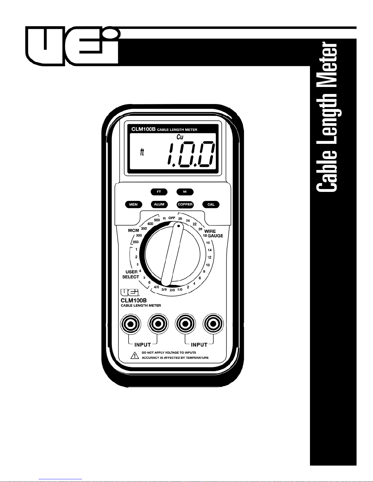
CLM100B
INSTRUCTION MANUAL
Page 2
Introduction
The CLM100B digital Cable Length Meter is an excellent tool to measure
spooled cable/wire. This best seller is built solid and supplied with a
Ruggedized boot for reliable field performance. Currently being utilized
by major utility companies, electrical contractors, wholesalers, and
installers where quick and accurate inventory management or measurements are needed for job accountability. Simply attach the Kelvin Clips
to both ends of the cable and adjust the indicator to the size wire being
measured. A temperature compensation circuit ensures accuracy by
compensating for the temperature of the wire.
Features include
• Increased resolution to 0.000
• Improved accuracy to ±1% of reading for lengths greater than
300 ft (100m)
• Measures copper and aluminum cables; covers the major
wire gauges
• 6 User programmable wire gauge settings
• 25 Pre-set wire gauge settings
• Automatic temperature compensation
• Reads in feet and meters
• Milliohm measurement capability
• Wire size: 26 ga – 4/0 ga
• 250 MCM – 5000 MCM
• Resistance 65
• Auto off
• Two easy-to-attach Kelvin Clip leads connect to cable
WARNING!
Make sure wire under test is not energized. Never apply voltage
to inputs.
NOTE: Temperature affects accuracy of readings. Please see accuracy
specifications. For best results, allow the CLM100B to attain the same
ambient temperature as the wire under test. The length of time this will
take depends on the ambient temperature. Typically it will take 10 to 15
minutes for the CLM100B to attain equal ambient temperature.
Safety Tips
Before using this meter, read all safety information carefully. In
this manual the word "WARNING" is used to indicate conditions
or actions that may pose physical hazards to the user. The word
"CAUTION" is used to indicate conditions or actions that may
damage this instrument.
Operating Instructions
Calibration Procedures
1. Turn the rotary selector from off to any position to turn the
meter on.
2. Set the rotary selector to “R” on the dial.
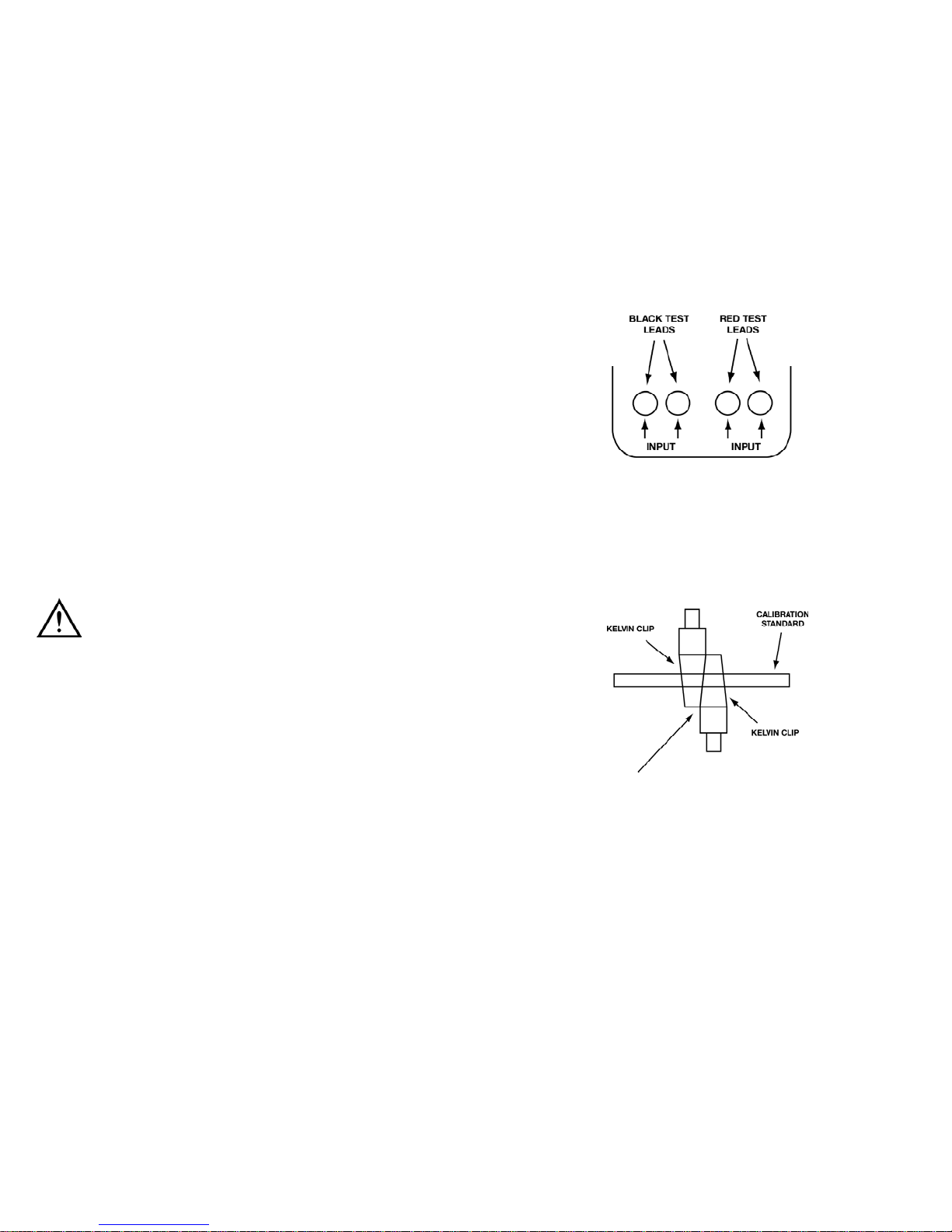
3. Insert the black test leads into one pair of input jacks and the
red test leads into the other pair of input jacks. (Ignore the gray
marking on the banana plug). This is very important to ensure
that the meter works correctly. If black and red test leads are
mixed the unit will give a false reading. (Fig 1)
4. Connect the Kelvin clips to the calibration standard. Make sure
the clips are as close together as possible. (Fig 2)
NOTE: Make sure the calibration standard is clean. The Kelvin
clips must be connected across the diameter of the standard.
Use the abrasive pad to clean the calibration standard.
NOTE: Make sure clips are as close together as possible. Use the
tips of the Kelvin clips when performing measurements on small
diameter wire.
5. Press and hold the ”CAL” button until all segments in the display
illuminate. This completes the calibration procedure and will
ensure all measurements are as accurate as possible.
6. Disconnect the leads from the standard.
Measuring Length of Wire
1. Turn the CLM100B on and perform the calibration procedure in
the “R” position.
2. Allow the CLM100B to attain the same temperature as the
wire under test.
NOTE: Temperature affects accuracy of readings. Please see
accuracy specifications. For best results, allow the CLM100 to
attain the same ambient temperature as the wire under test.
CLM100B-MAN P. 1
(Fig 2)
(Fig 1)
Page 3
WARNING!
Make sure wire under test is not energized. Never apply voltage
to inputs.
3. Strip the insulation back on each end of the wire being tested.
NOTE: Make sure both ends of the wire under test are clean and
the conductor is fully exposed. The insulation must be stripped
away so the Kelvin clips can be connected across the diameter of
the wire. Use the abrasive pad to clean the wire ends.
4. Using the selector on the CLM100B, turn to the size of wire
under test.
5. Press the ”COPPER” button if copper wire is being tested.
The ”CU” enunciator will illuminate in the top left corner of
the display.
6. Press the ”ALUM” button if aluminum wire is being tested.
The ”Al” enunciator will illuminate in the top left corner of
the display.
7. Press the ”FT” button if you require readings to be in feet.
The ”ft” enunciator will illuminate in the display.
8. Press the ”M” button if you require readings to be in meters.
The ”m” enunciator will illuminate in the display.
9. Connect a Kelvin clip to one end of the wire and the other
Kelvin clip to the other end of the wire.
10.Read the length of wire directly from the display. Please note
the ”k” enunciator illuminates if measurements are at or above
1000 feet/meters. For example, when the “k” enunciator is on
and you are measuring in feet, a reading of 15k ft would indicate
a length of 15000 ft.
11. Disconnect the test leads from the unit when not in use.
User Select Mode
This mode allows you to save the resistance of a user wire (see NOTE
below) for additional measurements of unknown lengths of the same
gauge wire. in addition, it enables you to accurately measure the length
of standard gauge wires. In this mode, you can measure the length of
any metal wire, the resistance of which can be measured, as well as
Copper or Aluminum wires.
NOTE: The sample length of user wires must be 20ft in FEET or 5m in
METER mode.
How to Save the Resistance of a User Wire
NOTE: You will need a 20’ (or 5M in meter mode) sample length of the
wire you are programming into the meter. This will measure the resistance of that wire and store a value to correctly measure longer lengths.
1. Turn the CLM100B on and perform the calibration procedure in
the “R” position.
2. Allow the CLM100B to attain the same temperature as the
user wire.
WARNING!
Make sure wire under test is not energized. Never apply voltage
to inputs.
3. Strip the insulation back on each end of the wire being tested.
NOTE: Make sure both ends of the wire under test are clean and
the conductor is fully exposed. The insulation must be stripped
away so the Kelvin clips can be connected across the diameter of
the wire. Use the abrasive pad to clean the wire ends.
4. Using the selector on the CLM100B, turn to a required memory
location in the User Select range. The meter has 6 internal
memory locations from 1 to 6, and the selected memory location
number will illuminate at the top left corner of the display. If the
selected memory location is occupied, the display shows
“
0000
”. If the selected memory location is empty, the display
shows “no”.
5. Press the ”FT” or ”M” button to select the measurement unit.
6. Press the Kelvin clip to one end of the 20’ section of the user wire
and the other Kelvin clip to the other end of the wire.
7. Press the ”MEM” button to enter the Memory function. The
“MEM” enunciator will illuminate in the top of the display.
8. Press ”CAL” button to store the resistance of the user wire.
9. If there is any stored resistance value in the selected memory
location, the meter will display “
SurE
”. In this case, press “CAL”
button again to store the new resistance value.
10. Press “MEM” button or turn the selector to any position in order
to exit Memory function.
Measuring Length of Wire in the User Select Mode
1. Turn the CLM100B on and perform the calibration procedure in
the “R” position.
2. Allow the CLM100B to attain the same temperature as the wire
under test.
WARNING!
Make sure wire under test is not energized. Never apply voltage
to inputs.
3. Strip the insulation back on each end of the wire being tested.
NOTE: Make sure both ends of the wire under test are clean and
the conductor is fully exposed. The insulation must be stripped
away so the Kelvin clips can be connected across the diameter of
the wire. Use the abrasive pad to clean the wire ends.
4. Select the required memory location in the User Select Mode
using the selector and the Listing label on the bottom case.
5. Press the “FT” or “M” button to select the measurement unit.
6. Connect a Kelvin clip to one of the wire under test and the other
Kelvin clip to the other end of the wire.
7. Read the length of wire directly from the display.
8. Disconnect the test leads from the meter when not in use.
CLM100B-MAN P. 2
Page 4
• When measuring wire for insertion into conduit, add extra wire
to compensate for the accuracy of the meter. For example, 205
feet of wire is needed to run inside a piece of conduit that is 200
feet long. (This would allow 2.5 feet on each end to attach the
wire.) At 205 feet and 70˚F, the cable length meter has an
accuracy of ±7 feet. In this case it would be safer to measure out
212 feet of wire. This would ensure that enough wire is available
for the application.
S p e c i f i c a t i o n s
Clearing Memory
1. Disconnect the test lead s from the meter.
2. Select the required memory location to be cleared in the User
Select range using the selector.
3. Press “MEM” button to enter the Memory function. The “MEM”
enunciator will illuminate in the top of the display.
4. Press “CAL” button. Then, the meter will display “
SurE
”.
5. Press “CAL” button again to clear the stored data.
6. Press “MEM” button or turn the selector to any position in order
to exit Clearing memory function.
Low Battery Indication
The “BAT” enunciator will illuminate in the lower left side of the display
to indicate battery voltage is low. The battery should be changed
immediately to ensure proper function and accuracy. Only alkaline
9 Volt batteries should be used.
Measuring Resistance
1. If the resistance to be measured is wire, follow steps 1 through
3 under “Measuring Length of Wire.” Then follow steps 2 and 3
below. If a discrete resistor is being measured, turn the cable
length meter on and perform the calibration procedure.
2. Read the resistance of the wire directly from the display.
Operational Hints
• Never apply voltage to the inputs.
• Temperature affects readings. Allow the CLM100B to attain the
ambient temperature of the wire under test.
• The sample length of user wires for the User Select Mode must be
20ft in FEET or 5m in METER mode.
• The Listing label on the bottom case of the meter enables users to
make a short memo of each user wire for the User Select Mode.
• Use a 9 volt alkaline battery only.
• If the meter is on and inactivate for approximately 15 minutes, the
meter will automatically enter into Sleep mode and display “----”.
Reactivate the meter by turning the selector to any position or
pressing any button.
• Use the test leads that come with the meter only. Other leads will
not work.
• Ensure that the test leads are clean and in good working order.
• Use an abrasive pad similar to the one provided to ensure the
wire under test is clean and free of oxidation.
• Ensure that the alligator clips are connected across the diameter of
the wire under test.
Measurement Range
Overall range limit: 0.5 to 100.0 kft
26 ga to 4/0 ga
250 MCM to 500 MCM
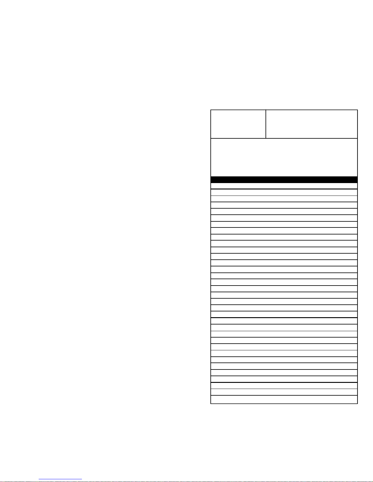
Due to the minimum and maximum resistance limits, specific wires
will have a range specific to that wire. Please refer to the following
table to determine the minimum and maximum length that can be
measured for specific gauge wires.
Gauge Min (Ft) Max (Ft) Min (M) Max (M)
500MCM 100.0 100.0k 30.5 30.00k
400MCM 90.0 100.0k 27.4 30.00k
350MCM 85.0 100.0k 25.9 30.00k
300MCM 80.0 100.0k 24.4 30.00k
250MCM 70.0 100.0k 21.3 30.00k
4/0 60.0 100.0k 18.3 30.00k
3/0 50.0 100.0k 15.2 30.00k
2/0 40.0 100.0k 12.2 30.00k
1/0 30.0 100.0k 9.1 30.00k
2 20.0 100.0k 6.1 30.00k
3 15.0 100.0k 4.6 30.00k
4 12.0 100.0k 3.7 30.00k
5 9.5 100.0k 2.9 30.00k
6 7.5 100.0k 2.3 30.00k
7 6.0 100.0k 1.8 30.00k
8 4.5 100.0k 1.4 30.00k
9 4.0 100.0k 1.2 30.00k
10 3.0 98.03k 0.9 29.88k
11 2.0 78.12k 0.6 23.81k
12 2.0 61.72k 0.6 18.81k
13 1.5 49.01k 0.5 14.94k
14 1.0 38.75k 0.3 11.81k
15 1.0 30.76k 0.3 9,377
16 1.0 24.44k 0.3 7,451
17 0.5 19.37k 0.2 5,906
18 0.5 15.35k 0.2 4,681
19 0.5 12.17k 0.2 3,712
20 0.5 9,619 0.2 2,931
21 0.5 7,629 0.2 2,325
22 0.5 6,059 0.2 1,846
23 0.5 4,809 0.2 1,466
24 0.5 3,819 0.2 1,164
25 0.5 3,029 0.2 923.4
26 0.5 2,399 0.2 731.4
CLM100B-MAN P. 3
Page 5
CLM100B-MAN P. 4
Resolution: 0.5 feet or 0.1 m (Length)
1 mΩ (Resistance)
Accuracy:
±(1% of reading + 1m or 3ft) < 100m or 300ft at 65˚ to 75˚F
±(1% of reading) > 100m or 300ft at 65˚ to 75˚
±(2% of reading + 1m or 3ft) < 100m or 300ft at 65˚ and above 75˚F
±(2% of reading) > 100m or 300ft below 65˚ and above 75˚F
Use the User Select mode for better measurement accuracies.
Resistance: 0 to 10Ω: ±(0.5% of reading + 3 LSD)
10 to 99.99Ω: ±(0.5% of reading + 10 LSD)
LSD = Least Significant Digit
Operation Temperature: 32˚ to 104˚F
Operating Humidity: 20% to 80% RH
Sleep Mode: After 15 minutes (Approx.)
Battery Life:
Depends on use. Typically 60 hours (180 hours in Sleep mode).
Extended measurement times can lower battery life to no less than
12 hours
Page 6
Limited Warranty
The CL M 100B is warranted to be free from defects in materials and workmanship for a
period of five years from the date of purchase. If within the warra n ty period your
instrument should become inoperative from such defects, the unit will be repaired or
replaced at UEi’s option. This warra n ty covers normal use and does not cover damage
which occurs in shipment or failure which results from alteration, tampering, accident,
misuse, abuse, neglect or improper maintenance. Batteries and consequential damage
resulting from failed batteries are not covered by warra n ty.
Any implied warranties, including but not limited to implied warranties of merchantability
and fitness for a particular purpose, are limited to the express warranty. UEi shall not be
liable for loss of use of the instrument or other incidental or consequential damages,
expenses, or economic loss, or for any claim or claims for such damage, expenses or
economic loss. A purchase receipt or other proof of original purchase date will be required
before warra n ty repairs will be rendered. Instruments out of warra n ty will be repaired
(when repairable) for a service charge. Return the unit postage paid and insured to:
1-800-547-5740 • FAX: (503) 643-6322
www.ueitest.com • Email: [email protected]
This warranty gives you specific legal rights. You may also have other rights which vary from
state to state.
CLM100B
Cable Length Meter
Copyright © 2007 UEi CLM100B-MAN 7/07
PLEASE
RECYCLE
 Loading...