

Vehicletool Mini VAG505A, Mini VAG506M, Mini VAG506, Mini V801 User Manual

Table of Contents
Safety Precautions…………….……….…………..…………..1
Product Information……….…………………………………..2
1. Applications……………….……….……………………….…..2
2. Available Functions…………….…..…………….……………2
3. Supported Systems……………………………….…………..2
4. Professional function.………………………………………...2
5. Main features…………………………………….……………3
6. Appearance and Key Descriptions ………………………3
Operation Instructions……………….....……………………..6
1. Connect the Tool……………….………………..…………….6
2. Diagnosis system…………………..…..…………...…………6
2.1 Select Control Unit… ……………….….….…………....6
2.2 Select System.………...…..……………………..….…..7
2.3 Connect with vehicle’s ECU.………...…..……...……..7
2.4 Function………………….………….………….……..….8
2.5 Read Version ……...………..……………………..…….8
2.6 Read Fault codes.………..……………………..……..8
2.7 ERASE Fault codes…….…………………….……..9
2.8 Read measuring data value……………………..…..10
2.9 Output test.…………………………………..…….….11
2.10 Basic setting……….…………………………..….…11
2.11 Adaptation………….…….………….………………..12
2.12 Coding……..……..……..….……………………….…13
2.13 Login the system………….…………………………..13
2.14 System being ready…………………………………..14
2.15 Advanced ID ……………………...………….……….14
3. Professional function…………………………………….. …15
4. Setting ……..……..……..….……………………….…..……20
5. The use of Upgrading software………...………..….………22

Mini VAG505A/VAG506M/VAG506/V801
2
To prevent personal injury or damage to vehicles and/or the scan
tool, read this instruction manual first and observe the following
safety precautions at a minimum whenever working on a vehicle:
Always perform automotive testing in a safe environment.
Wear safety eye protection that meets ANSI standards.
Keep clothing, hair, hands, tools, test equipment, etc. away from all
moving or hot engine parts.
Operate the vehicle in a well ventilated work area: Exhaust gases are
poisonous.
Put blocks in front of the drive wheels and never leave the vehicle
unattended while running tests.
Use extreme caution when working around the ignition coil, distributor
cap, ignition wires and spark plugs. These components create
hazardous voltages when the engine is running.
Put the transmission in PARK (for automatic transmission) or
NEUTRAL (for manual transmission) and make sure the parking
brake is engaged.
Keep a fire extinguisher suitable for gasoline/chemical/ electrical fires
nearby.
Don’t connect or disconnect any test equipment while the ignition is
on or the engine is running.
Keep the scan tool dry, clean, free from oil/water or grease. Use a
mild detergent on a clean cloth to clean the outside of the scan tool,
when necessary.
Location of Data Linking Connection.
Refer to the picture of OBD-II 16pin as the following. For VW GOLF, it
locates in the right side of steering column; for Jetta, it locates in the left
side of the bottom of the dashboard which is at the driver’s ca. For more
details, please refer to the vehicle repairing manual.
Safety Precautions

Mini VAG505A/VAG506M/VAG506/V801
3
1. Applications
Mini VAG505A/VAG506M/VAG506/V801 is the higher version with
powerful function. It supports all cars under brand of VW, AUDI,
SKODA and SEAT. With its smart appearance but powerful function,
it can be conveniently used and can be run detachedly without
support of PC. And it Support UDS vehicle protocols.
2. Available Functions
Controller Info
Fault Codes
Clear Codes
Measure Blocks
Output Tests
Basic Settings
Adaptation
Coding
Security Access
Readiness
Advanced ID
3. Supported Systems
Engine
Transmission
ABS Brakes
Auto HVAC
Central control
Airbags
Steering wheel
Instruments
Immobilizer
With other systems totally over ten here not listed one by one.
4. Professional function.
Oil Reset
Airbag Reset
Odometer
Product Information
Mini VAG505A/VAG506M/VAG506/V801
4
Stop/Activate SBC
AUDI O2 sensor service
VW O2 Sensor service
NOTE: Only V506/V801 has the following features:
Throttle adjustment
Tilt Angle sensor calibrate
5. Main features
Favorable----about only 10% of that of professional tool.
Powerful function-----with all the function of VAG1551/1552.
Powered via diagnostic connector, no need of power exteriorly
charged.
Conveniently connection and simply operation.
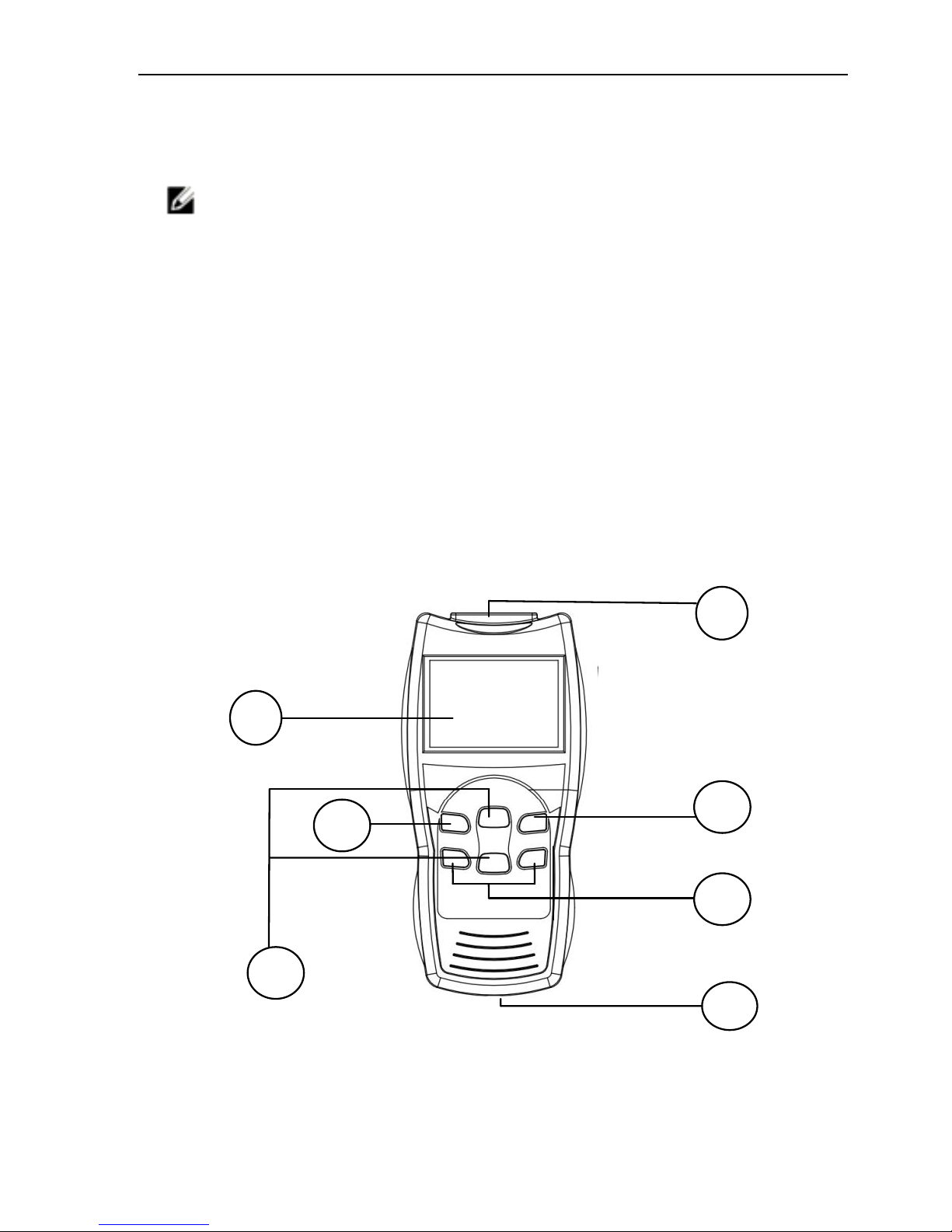
6. Appearance and Key Descriptions
V801/VAG506
① Diagnostic extension cable: OBDII -16PIN
② LCD screen: VAG506 is backlit LCD, 128*64 pixel display. V801 is 2.8"
TFT true color 320*240
③ ENTER key: confirm selection and enter
④ Esc key: go back to the previous screens
2
3 1 4 6 5
Mini VAG505A/VAG506M/VAG506/V801
5
⑤ UP/DOWN arrows: moves the selection pointer and scrolls up or down
⑥ LEFT/RIGHT arrows: move cursor. For V801 also to flip page
⑦ USB interface: connect to USB cable
Dimensions: Length 201mm (7.9"), Width 94mm (3.70"),Height 36mm
(1.74")
OBDII connector, 900mm (35.4")
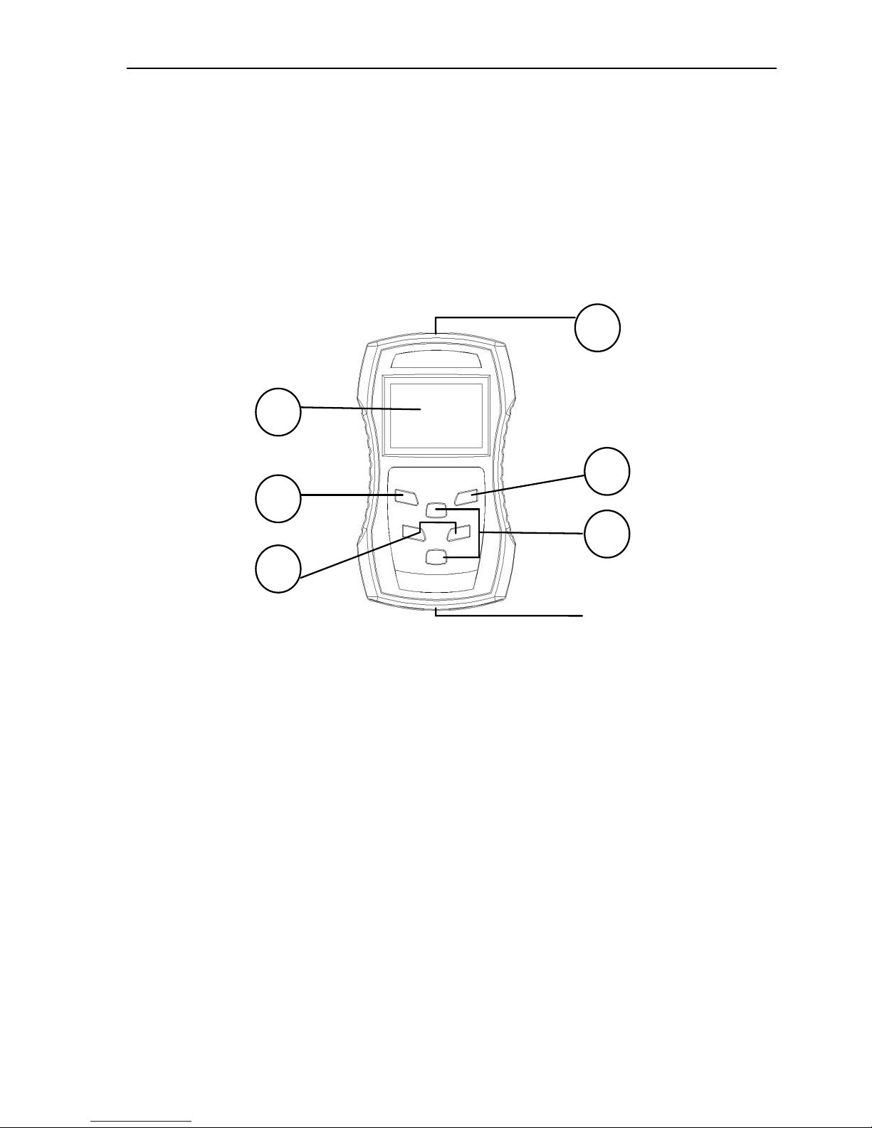
VAG506M
① OBDII Connector: connect car and the scan tool
② LCD screen: Backlit LCD, 128*64 pixel display.
③ ENTER key: confirm selection and enter
④ Esc key: go back to the previous screens
⑤ LEFT/RIGHT arrows: move cursor.
⑥ up/down arrows: moves the selection pointer and scrolls up or down
⑦ USB interface: connect to USB cable
Dimensions: Length 125mm (4.92"), Width 75 mm (2.95"),Height 23 mm
(0.90")
OBDII connector, 735mm (28.9")
2
1 5 3 4 6
Mini VAG505A/VAG506M/VAG506/V801
6
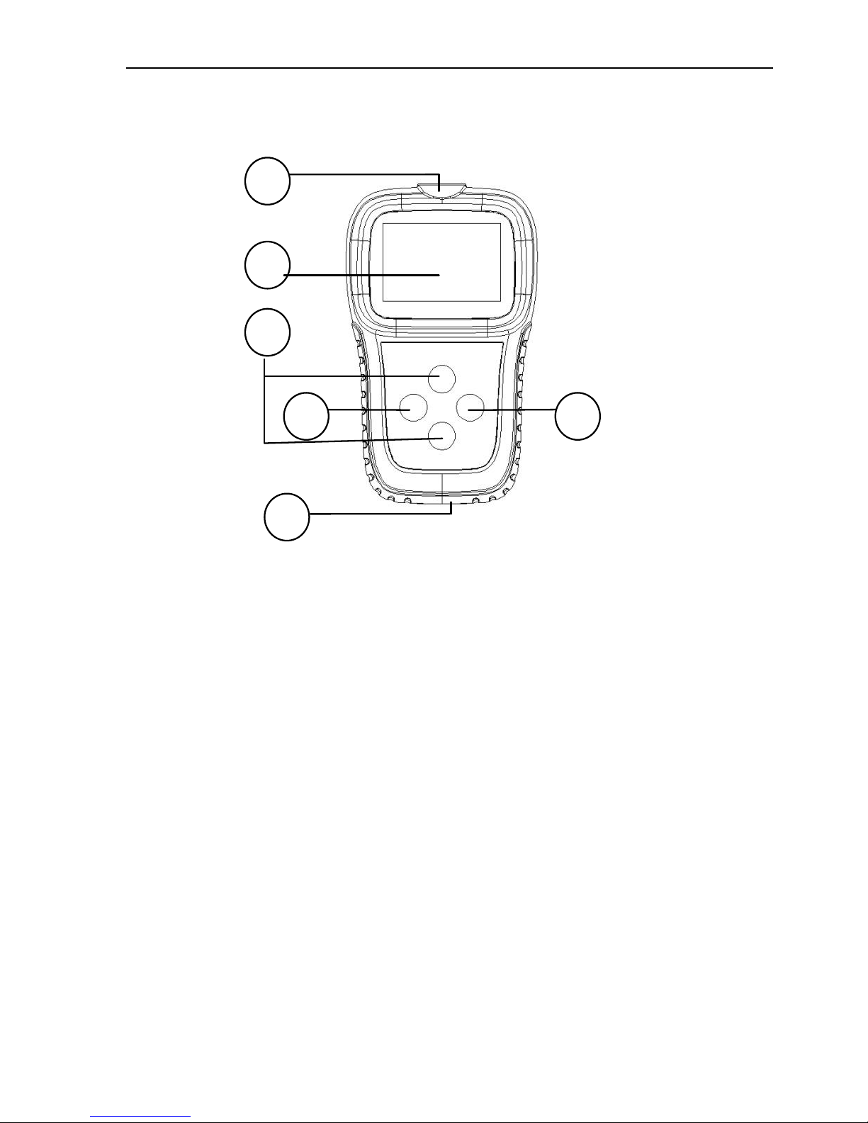
Mini VAG505A
① OBDII Connector: connect car and the scan tool
② Screen: 128*164 pixel display, Backlit LCD
③ ENTER: confirm selection and enter
④ ESC: go back to the previous screens
⑤ UP/DOWN: up and down to choose different menu, press it for 1-2
seconds to choose the number of places(move the cursor)
⑥ USB interface: connect to USB cable
⑦ Press UP/DOWN button for one to two seconds, the key change to
LEFT/RIGHT
Dimensions: Length 117mm (4.70"), Width 72mm (2.83), Height 22mm
(0.87")
OBDII connector, 735mm (28.9")
Product Specifications
● Operating Temperature- 0 to 50
O
C(-32 to 122OF)
● External Power: 10.0 to 15.5 volts provided via vehicle battery
6 5 3 4 2
1
Mini VAG505A/VAG506M/VAG506/V801
7
1. Connect the Mini VAG506/VAG506M/VAG506/V801
1.1 Turn the ignition off.
1.2 Locate the vehicle's 16-pin Data Link Connector (DLC).
1.3 Plug the OBDII connector to the vehicle’s DLC.
1.4 Turn the ignition on. Engine can be off or running.
The tool will auto start, the following screen will be displayed.
Wait a moment, the screen will auto display the Main Screen.
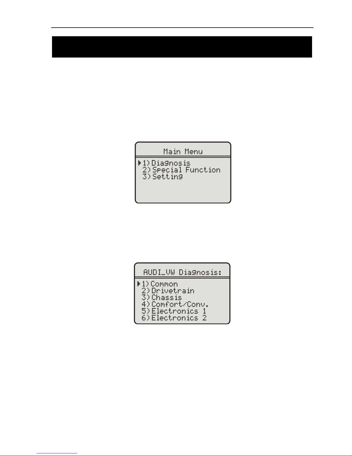
Figure 1
2. Diagnosis system
With the scan tool in Main Screen (Figure 1.1), select the Diagnosis,
and press ENTER button. Wait for the Diagnosis screen to appear. The
scan tool will list all Control Unit.
Figure 2
2.1 Select Control Unit
With the scan tool in Control Mode screen (Figure 2), use UP/DOWN
scroll button to select system, and press ENTER button. The scan tool
will list all systems, and you can manually select the detecting system,
the scan tool will list all Systems screen (Figure 2.1).
Operation Instructions
Mini VAG505A/VAG506M/VAG506/V801
8
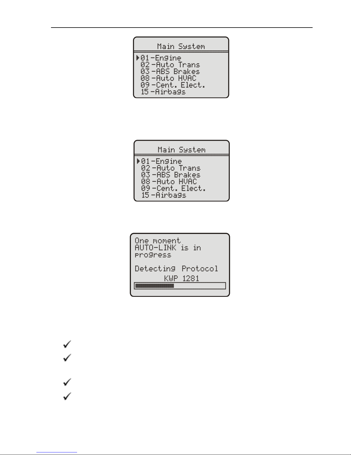
Figure 2.1
2.2 Select System
With the scan tool in System screen (Figure 2.1), use UP/DOWN scroll
button to select the detecting system, and press ENTER.
Figure 2.2
2.3 connect with the vehicle’s ECU
If the scan tool fails to communicate with the vehicle’s ECU
(Engine Control Unit), a “Fail to connect” message shows up
on the display.
Verify that the ignition is ON.
Check if the scan tool’s OBD II connector is securely connected to
the vehicle’s DLC.
Verify that the module is supported.
Turn the ignition off and wait for about 10 seconds. Turn the ignite on
back to on and repeat the procedure from step 2.3
 Loading...