

Vehicle Systems VBV-750, VBV-750M, VBV-700CM, VBV-700C Instruction Manual
BV-750
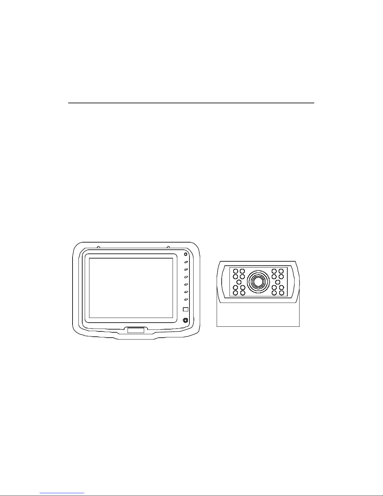
VEHICLE CCTV SYSTEM
VBV-750
Model:
VBV-750M MONITOR
VBV-700CM CONTROL MODULE
VBV-700C CAMERA

-free
anual contains
-view mirror systems, and will
-view vision when installed and maintained properly.
CTV system is not intended in any way to be a substitute for
rors or for any other motor vehicle or boat
VBV-700C CAMERA
-angle lens provides a broad viewing area (110°Diag.)
VBV-750M TFT LCD COLOUR 5.0" MONITOR
ion, and Clock
-by switch
-700CM CONTROL BOX
-700C CCD CAMERA:
Camera
Camera bracket
Attachment screws with washers
Wind deflector
-750M MONITOR:
Monitor
Monitor bracket
-700CM CONTROL BOX
Power cable
-20 meter cable with waterproof connector. Oil, gas, grease
STALLATION
mera will compromise the Waterproof seal.
al voltages inside the monitor. There are no user serviceable
he monitor could cause extensive damage.
-700C CAMERA
camera and bracket.
f dust, dirt and moisture on the camera lens. (See Fig.2)
-750M MONITOR
or rear-mounting bracket to attach the monitor
-700CM CONTROL-BOX
. Attachment point must be sturdy enough to
-to- cable connection is waterproof. The cable-to-control-box
he rectangular box end attaches to the control-
(See Fig. 6.)
ire the cable securely.
- diameter hole into vehicle body near the
nnector to extension cable in vehicle.
-box: Insert extension cable into camera #2 (R) position. If 1
eration.
FUNCTIONS AND OPERATION
MONITOR (see Fig.7)
1) POWER LED
When the red LED is turned on, it indicates power on.
Putting the gear into the reverse, the view of camera 2 shall be shown on the
monitor.
2) Power ON/OFF Switch
3) ? +, ? - CONTROL BUTTON
. This button can adjust a speaker’s volume and also Menu adjusts.
§ Turning up the option, press this button and it will be up
gradually. While the option being up, the marks below are
shown on the monitor.
§ Turning down the option, press this button and it will be down
gradually. While the option being down, the marks below is
shown on the monitor
. The function above is preceded than any others.
4) "MENU" Button
If you press the button "MENU", the list of function will be shown on the monitor.
§ PICTURE
§ SYSTEM
§ OPTION
§ CLOCK
Selectable function lists disappear within seconds if there is no new input sign.
You can choose or select easily any function on the menu lists.
5) SEL.
SELECT CONTROL BUTTON
Use these buttons in order to select the option.
6) Camera selector button
Following the turns below, it can be selected that CA1, CA2.
The OSD indicates which camera is operating now.
7) REMOTE-CONTROLLER SENSOR
The monitor is to be operated by a remote-controller.
To operate the system with the remote- controller turn the remote-controller
towards the sensor on the face of monitor.
8) Earphone Jack
9) BRACKET RAIL
Mounting bracket is adjustable.
METHOD OF ADJUST
1. PICTURE CONTROL
1) Press the "MENU" button
2) Select “PICTURE”
3) Move the cursor to the " CONTRAST, BRIGHT, COLOR, SHARP AND TINTS"
with the SEL button.
4) Press the "? + or ? -” button.
5) Select one of five options.
6) Choose it with the " ? + or ? - “button.
7) Press the "MENU" button
2. SYSTEM CONTROL
1) Press the "MENU" button
2) Select “SYSTEM”
3) Move the cursor to the "INPUT, COLOR SYSTEM, BLUE BACK,
LANGUAGE, " with the SEL button.
4) Press the "? + or ? - " button.
5) Select one of five options.
6) Choose it with the " ? + or ? -” button.
7) Press the "MENU" button
3. OPTION CONTROL
1) Press the "MENU" button
2) Select “SEL”
3) Move the cursor to the "HORIZONTAL, VERTICAL" with the SEL button.
4) Press the "? + or ? - " button.
5) Select one of two options.
6) Choose it with the " ? + or ? - " button.
7) Press the "MENU" button Press the "MENU" button
4. CLOCK CONTROL
1) Press the "MENU" button
2) Select “CLOCK”
3) Move the cursor to the "TIME, ON TIME, OFF TIME, ATTENTION, CH-TIME"
with the SEL.- button.
4) Press the "? + or ? - “button.
5) Select one of five options.
6) Choose it with the " ? + or ? - " button.
7) Press the "MENU" button Press the "MENU" button
REMOTE CONTROLLER (see Fig.8)
1) MODE (Mode):
Press this button; users can realize the five picture statuses of Standard,
Soft, Vivid, light and Personal.
2) POWER (Power switch):
Press this button is to turn off the monitor, press it again is to turn on the
machine.
3) MUTE (Mute):
Press this button, sound disappears, press it again or ? + or ? - is to resume
normal sound.
4) CALL (Call):
Press this button is to display AV character currently watching.
5) TIMER:
Time setup of sleep off, it is used to set the time off within 120 minutes.
6) C / E / R / P / G:
Press this button can realize the switch of Chinese, English, Russian, Arabic
and German menu.
7) CALE:
Press this button is to show Year, Month, Day and Week. Press ? SEL or ?
SEL is to adjust the Year, press ? + or ? - is to adjust the Month.
8) VIDEO (CA1 / CA2 shift):
Press this button is to realize switch between CA1 and CA2 pictures.
: Press this button is to flip the picture horizontally.
: Press this button is to flip the picture vertically.
CAMERA
1. Waterproof connector (See Fig.9)
CAUTION
1. DO NOT OPEN THE CAMERA CASE. This will break the camera’s
Waterproof seal. If evidence of tampering is detected, the warranty Will be
considered void.
2. Do not recommend mounting the camera near the lower area of the
vehicle (e.g. bumper). This reduces the view of the camera and increases
the chance of physical damage to the camera.
3. Use only the Inner Hexagonal screw and washers to mount the camera.
MAINTENANCE
Remove dust and dirt with a damp soft cloth. Heavier dirt should be
removed with a damp soft cloth and mild detergent. Do not use strong
cleaning agents containing gasoline, thinner, benzene or alcohol. These
substances may damage the exterior surface of the monitor.
CAUTION
1. Before drilling, be sure no cable or wiring is on the other side. Be sure to
drill a 20mm - diameter hole only.
2. Feed as much cable as possible into vehicle and clamp securely. This
reduces the possibility of it being hooked or snagged.
3. Keep all cables away from HOT, ROTATING and ELECTRICALLY
NOISY components.
4. To increase protection of cable, place all excess wire and extension cable
in convoluted tubing.
5. Do not twist camera cable and do not cut camera pigtail or cable.
SPECIFICATIONS
VBV-700C CAMERA
PICK-UP DEVICE INTERLINE TRANSFER TYPE CCD
TV SYSTEM PAL
PICTURE ELEMENTS 500(H) × 580(V) PAL
SENSING AREA 4.9mm x 3.7mm
IMAGE SIZE 1/3 INCH
SYNCHRONIZATION INTERNAL
HORIZONTAL RESOLUTION 380 TV LINES
REQUIRED ILLUMINATION 0.1 LUX MINIMUM / F1.2
SIGNAL TO NOISE RATIO MINIMUM 50DB(AT AGC OFF)
POWER SUPPLY 12VDC
POWER CONSUMPTION 2.4W(AT 12V DC)
CURRENT CONSUMPTION MAX. 350Ma
LENS ANGLE 110º
OPERATION TEMP -20°C TO +70°C
STORAGE TEMP -30°C TO +60°C
VBV-750M MONITOR
PICTURE TUBE: 5.0” INCH, COLOUR TFT -LCD
DEFLECTION ANGLE: 45°(LEFT/RIGHT), 10°(TOP), 30°(DOWN)
POWER SOURCE: 12-24 VDC
(WITH USE OF CONTROL -BOX)
12 VDC (WITHOUT USE OF CONTROL-
BOX)
POWER CONSUMPTION: ~ 8W/700MA MAXIMUM
OUTPUT VOLTAGE: 9.6VDC
TV SYSTEM: PAL/NTSC
VIDEO INPUT/OUTPUT: COMPOSITE VIDEO SINGLE
1VP-P 75 OHM
RESOLUTION: 960(H) X 234(V)
CONTRAST: 150:1
VIEWING ANGLE (U X D X R/L) 15 X 35 X 50
OPERATING TEMPERATURE: -10°C ~ TO +60°C
STORAGE TEMPERATURE: -25°C ~ +70°C
WEIGHT: 0.43 KG
DIMENSIONS: (W X H X T)mm 163 X 125 X 30.5
VBV-700CM CONTROL BOX
POWER INPUT 12-32 VDC
POWER OUTPUT 11-12 VDC, 2A
POWER OUTPUT MAX. 20 W
VIDEO SYSTEM PAL
VIDEO OUTPUT 1V P-P 75 OHM
VOLTAGE OUTPUT 12 VDC
OPERATING TEMPERATURE -10° TO +60°C
STORAGE TEMPERATURE -25° TO +80°C
CASE MATERIAL ALNICO
WEIGHT ~0.5 KG
DIMENSIONS (W X H X D)mm 146 X 37 X 79
DISCLAIMER
The use of the VBV-750 Vehicle CCTV system does not guarantee or
promise that the user will not be in an accident or otherwise not collide with
an object. The vehicle CCTV system is not intended in any way to be a
substitute for careful and cautious driving or for the consistent adherence to
all applicable traffic laws and motor safety regulations. This product is not
intended to be a substitute for rear-view mirrors or for any other motor
vehicle or boat equipment mandated by law.
BRIGADE ELECTRONICS PLC
TEL: +44 (0) 870 744 1500
FAX: +44 (0) 870 744 1502
Email: sales@brigade-electronics.co.uk
Website: www.brigade-electronics.co.uk
ENGLISH
V
VBV
-
750 VEHICLE CCTV SYSTEM

Fig 1
Mount camera assembly
high-mounted. Centred.
Camera mounting
hole pattern.
 Loading...