

Vega Industries VLB-44 Instructions Manual
Vega VLB-44 Lantern 25 Jan 2011 - Rev 9
VEGA INDUSTRIES
VLB-44 LED LANTERN INSTRUCTIONS
General Information
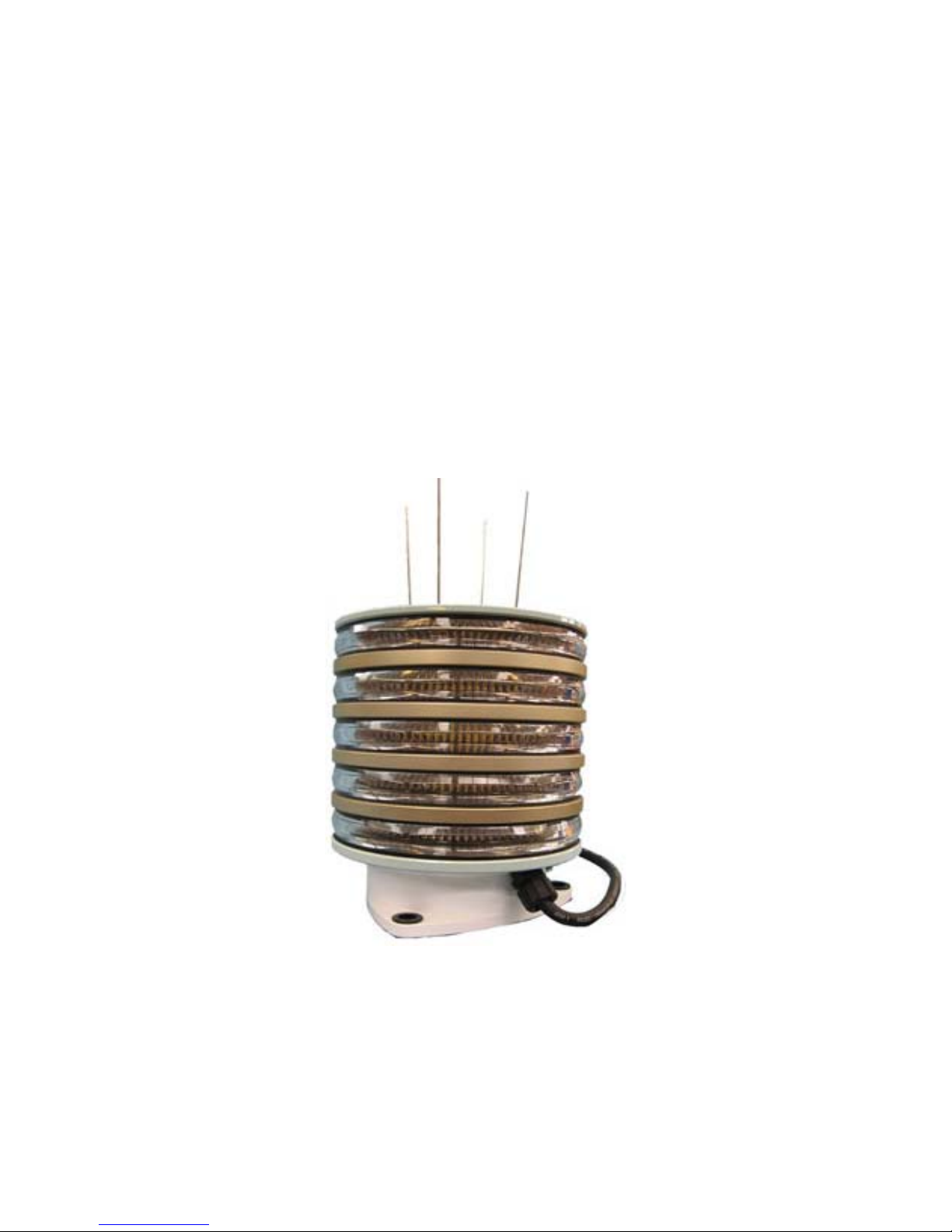
The Vega VLB-44 LED lantern is a versatile lantern capable of being installed on buoys, fixed
structures and lighthouses. It is generally used when a self-contained LED lantern is not feasible
or cost effective to operate. The lantern is available in white, yellow (except 2.5 degree), red and
green, and three vertical divergences; 10 degrees (total to 50% peak intensity) for use on buoys, 5
degrees for fixed structures and 2.5 degrees for lighthouses. The narrow divergence (2.5 degrees)
concentrates light in the horizontal plane, but requires a stable platform to remain level. This
regulates the 2.5 degree lantern to lighthouses or rock-solid structures unaffected by wind or
waves.
The VLB-44 is available with up to 8 tiers of LEDs to increase intensity. This lantern requires an
external 12 VDC power source from a DC power supply or a legacy solar power system
consisting of solar panels and rechargeable lead-acid batteries. Note: due to the nature of LED
lanterns this signal can not be used with a color sector.
Selection Criteria
Intensity selection should be based on the operational requirements of the aid. To determine the
intensity requirements for any aid, Districts shall use the standard procedures for selecting an
AtoN light signal as prescribed in the AtoN Technical Manual (Chapter 6, Section 6.B, page 6-1)
and the Visual Signal Design Manual (Chapter 3). These references describe how operational
Vega VLB-44 5-Tier LED Lantern
1

Vega VLB-44 Lantern 25 Jan 2011 - Rev 9
Selection Criteria (cont’d)
range, luminous range, light color, light characteristic, background lighting, and meteorological
visibility are used to calculate intensity needs.
The VLB-44 has a feature that allows the lantern to produce the same effective intensity
regardless of flash rhythm. The intensities cannot be tabulated because the operating current and
peak intensity capabilities are different for each flash rhythm. Use one of the solar design
spreadsheets to select the lantern, number of tiers, color and flash rhythm, available at:
http://www.uscg.mil/hq/cg4/cg432/publications.asp
Nonstandard and custom flash rhythms, along with double stack (16 tier) lantern combinations
are not listed in the solar design spreadsheets. In this case, use the Vega VLB-44 Current
Calculator available at the above link and enter the data in the Old Solar Sizing Program,
available at the same link. Assistance in using the Old Solar Sizing Program is available from
COMDT (CG-432A) http://www.uscg.mil/hq/cg4/cg432/organization.asp
For most desired effective intensity settings, the user has the option of picking lanterns with
different numbers of tiers. For a desired effective intensity, the greater number of tiers will lower
the overall power draw. However, more tiers than necessary will significantly increase the cost
of the lantern and the height. Unless there is a compelling reason, pick the lantern with the fewest
number of tiers.
LED Version – The capabilities of LEDs change rapidly. Periodically Vega uses new LEDs in a
specific lantern (or group of lanterns). This impacts the lantern’s intensity values, current draw
and solar sizing. In order to identify the LEDs used in a lantern, Vega uses a 3-digit number to
identify the “LED version.” For example, the white LEDs available in late 2007 and early 2008
were designated LED version 421. LEDs available in mid 2008 were designated version 422.
The Solar Sizing Programs used to size a solar power system for VLB-44 have a picklist that is
used to select the LED version. The picklist choices depend on the user-selected lantern and
color. The newest LED version is the upper-most choice in “LED version” picklist.
When ordering a lantern, one needs to know what LED version will be shipped with the lantern.
If ordering directly from Vega, contact Vega or COMDT (CG-432A) to find out what LED
version will be provided. If a VLB-44 will be sent from the supply stocked at the SFLC then
contact COMDT (CG-432A) to learn what LED version will be provided.
For lanterns in-hand, the LED version can be determined by: (1) the LED version may be
written on the lantern’s label; (2) the LED version can be retrieved from the lantern using the IR
programmer (see instructions below in the “Programming” section); or (3) use the Vega VLB-44
“Installation and Operation Manual” that was shipped with the lantern (go to the table at the back
of the manual that corresponds to the color and vertical divergence of the lantern – the LED
version is the number in parenthesis between the color and “Current (mA)”).
.
.
2

Vega VLB-44 Lantern 25 Jan 2011 - Rev 9
Purchase
CGHQ established a 5 year requirements contract with Vega Industries. Orders for lanterns are
placed through Ms. Jing Liu at the SILC in Alameda, CA. Provide a copy of the funded
procurement request to her with the “CIMS bound box” checked, routed to inbox 7513C and she
will draft a delivery order with Vega. You must contact Mr. Jon Grasson at COMDT (CG-432A)
upon receipt of the lanterns so payment can be authorized. Current pricing for Vega lanterns is
available from your training team chief or COMDT (CG-432A)
http://www.uscg.mil/hq/cg4/cg432/organization.asp
.
The following VLB-44 lanterns will be stocked at the SFLC in project 98A (free-issue) for
approved buoy, fixed aid and lighthouse projects (contact Son Nguyen at above link.)
VLB-44-10 Single tier buoy lanterns, white with a high base (all lanterns include bird spikes)
VLB-44-5 Single tier fixed aid lanterns, red, white and green
VLB-44-2.5 Eight tier lighthouse lanterns, white
Remote 1 Vega infrared remote control
Lanterns not listed above must be purchased directly from Vega via the SILC using the following
format (it would be helpful to the contract specialist if the Item No. listed in the contract is
included with your order):
VLB-44-(Color)-(Divergence)-(Tiers)-(Base Mount)
Where: Color = WHT, RED, GRN, YEL
Divergence = 2.5, 05, 10 for lighthouses, structures or buoys, respectively
Tiers = 1T, 2T…..8T for 1 through 8 tiers.
Base Mount = 3H (for 3 hole mount, regular base; if replacing a 250mm, you
can order a 4-hole mount; 4H), use HB for high base on buoys.
Example: VLB-44-WHT-2.5-6T-3H White, 2.5 degrees, 6 Tier, 3-hole mount.
A requirements contract that lists all VLB-44 combinations and pricing was distributed to
districts in September 2009 and updated annually as options are exercised.
Additional Notes:
• You can specify the desired intensity setting and flash rhythm when ordering.
• A high base is required for buoy installations to prevent obstruction by the lantern ring
when viewed at low heights-of-eye.
• VLB-44 High Base; change the suffix from 3H to HB in the VLB-44 item description.
• Bird spikes are included. Replacement bird spikes are available; order part number 138-
800, Bird Spikes.
• Standard cable length is 1.5 meters for VLB-44 2.5 and 10 degree versions. 3 meter
cable is standard for 5 degree versions (longer cables are available upon request).
• Mount-Kit-2 (ordered separately) is used to stack two VLB-44-8T lanterns (see design
considerations) to increase the intensity for lighthouse applications.
3
Vega VLB-44 Lantern 25 Jan 2011 - Rev 9
Programming - Overview
The lantern must be programmed to the proper flash rhythm and intensity before deployment.
The lantern is programmed using the Vega Infrared (IR) Remote Control or any RCA TV remote.
There are about 30 different RCA TV Universal Remote Controls. Non-Vega remotes must be
initialized so that the remote can communicate with the lantern. Different models have different
initialization procedures. If the remote purchased uses a 3-digit code use code 0 6 2 If the remote
uses a 4-digit code, then use code 1 0 6 2. Consult the instructions that come with the remote.
Follow the “Direct Entry Method” for programming a TV as shown in the instructions.
Initialization will likely take one of the following two forms:
Press and hold CODE SEARCH until red light on remote turns on
Press TV red light on remote will blink once
Enter 0 6 2 red light will blink once after each entry
or
Press and hold TV keep holding TV button!
Enter 1 0 6 2 while still holding TV button
Release TV button
(Note: the codes for RCA remote needs to be verified. Use the Vega remote until positive confirmation is
received.)
You are now ready to program the Vega VLB-44 lantern.
Gather the information needed to program the lantern; intensity and flash rhythm code (note: if
the lantern is purchased directly from Vega for a specific project it may come pre-programmed.
You can check the entries; see Programming – Reading a Program Setting detailed later in this
instruction.)
Standard CG Flash Rhythms
Rhythm Code Rhythm Code Rhythm Code
FL2.5 (0.3) 310 Mo(A) 801 FL (2) 6 416
FL4 (0.4) 321 Iso 2 100 FL (2) 5 406
FL6 (0.6) 337 Iso 6 104 FL (2+1) 6 472
Q 601 Oc 4 205 Fixed 000
The following is a list of nonstandard, but common flashed lighthouse rhythms used at CG aids.
Also posted is the actual flash (FL) and eclipse (EC) times of each rhythm.
Non-Standard Flash Rhythms
Rhythm Code FL EC FL EC
FL5 (0.5) 329 0.5 4.5
FL7.5 343 0.8 6.7
FL10 350 1.0 9.0
FL15 354 1.0 14.0
FL (2) 10 428 1.0 1.0 1.0 7.0
FL (2) 15 435 1.0 2.0 1.0 11.0
FL (2) 20 436 1.0 3.0 1.0 15.0
4

Vega VLB-44 Lantern 25 Jan 2011 - Rev 9
Programming - Overview (cont’d)
For flash rhythms not listed on the previous page, consult Vega’s IR Programmer manual
supplied with each programmer for a nonstandard code. Pay careful attention to the existing
ON/OFF times of the light and try to match the rhythm to one listed in the manual. Note that
existing rotating beacons generally have very short flash lengths (0.05-0.2 seconds), but when
replicated by the VLB-44 the flash length is increased to 0.5-1 second (typical) with a
corresponding reduction in eclipse time (period remains the same). Strive to achieve a duty cycle
of around 10% (duty cycle is the sum of the on-times divided buy the period). As an example, a
DCB-224 in a lighthouse with a FL(2)W15 rhythm may have an existing flash rate of 0.1s FL,
4.9s EC, 0.1s FL, 9.9s EC (as detailed in the Light List). It is not practical to flash the VLB-44 at
a 0.1 second rate. A typical rhythm would be 1s FL, 4s EC, 1s FL, 9s EC. Note that the period
remains the same (15 seconds) and the duty cycle is 2s/15s x100=13.3% (close to the desired
10% mentioned above). If this desired rhythm is not listed in the IR Programming manual (it
isn’t for this example), see the section on custom rhythms.
Intensity Setting – The intensity setting or value can be found on the solar design spreadsheet,
form 3213A or the district work order. A value of 1390, for example in the effective intensity
(cd) block refers to an effective intensity of 1390 candelas and the code for that intensity is 1390.
Note: all
intensity codes are 4 digits, so an effective intensity of 77 candelas is entered as code
0077; 109 candelas is entered as code 0109. Note the intensity setting in the aid log and in
IATONIS under notes so that a replacement lantern can be programmed to the correct intensity.
Improper settings can affect the nominal range and the solar sizing of the aid.
5

Vega VLB-44 Lantern 25 Jan 2011 - Rev 9
Programming Notes:
• The lantern must be programmed with power applied in daytime conditions outside or in
a lighted room (fluorescent lighting may not allow proper programming).
• Programming entries must not lag by more than 10 seconds or the lantern will exit the
programming mode. Write down the programming codes for each session to avoid
delays.
The Infrared Receiver (IR) is located in the base of the lantern through a window just
•
above the label. Aim the remote control here 6-12” from the lantern.
The lantern enters the programming mode by pressing the “red standby”, “power” or
•
“program” key on the remote for 5 seconds. The lantern will display 4 quick flashes (.1
sec on, 0.1 sec off) indicating that it is in the programming mode.
Each successful numeric keypad entry will result in 1 flash for each key pressed.
•
Wait for the lantern to flash before entering the next digit (don’t rush programming).
•
When the programming code is recognized, the lantern will display the 3 or 4 digit code
•
with a series of quick flashes with a gap of 0.5 seconds between each “number” of the
code. A zero (0) is displayed as a 2 second flash.
If the programming code is not recognized, the lantern will display 3 quick flashes and
•
the lantern will return to the programming mode (re-enter entire program code again).
When exiting programming mode, the lantern will display 2 quick flashes, followed by a
•
short pause and another 2 quick flashes, then display the flash rhythm for 16-20 seconds.
If the VLB-44 is the main light controlled by a SACII/III, the lantern must be
•
commanded on both day and night, and intensity set for both day and night. The daylight
control function is performed by the SACII/III and the lantern is controlled by power
being applied at dusk and secured at dawn by the SACII/III. If this is not done there is a
conflict between the daylight controls in the lantern and SACII/III. Setting the intensity
for both day and night is necessary to ensure that the light displays the correct intensity
during the transitions between night/day and day/night. See page 8 for specific
instructions.
Programming
Apply 12 VDC to the input leads of the lantern. Black
negative. The green/yellow sync wire is left disconnected. If you are using a power supply, be
sure that it is capable of providing enough power; approximately 1.25 amps per tier.
The lantern will power up in the default setting from the factory (or if it came pre-programmed).
After 10 seconds it will monitor the ambient light level and if bright enough will turn off (the
desired mode for programming). If, for some reason the voltage at the lantern is below 11.0
volts, the lantern will shut down to conserve energy and protect the battery and will not relight
unless power is reapplied or the voltage exceeds 13.0 volts and at least one daytime cycle is
detected (to prevent oscillation on and off at night).
The programming sequences are grouped together so that all codes are entered at one time. It is
suggested and acceptable to perform the programming operation in two separate sessions
(detailed A & B), however the code sequences can be entered sequentially after confirmation of
the code, but before the lantern exits the programming mode (within 10 seconds after the
confirmation flashes.) The two programming sequences required for most sessions are: flash
rhythm and intensity.
or brown is positive and white or blue is
6
 Loading...