

VEGA Grieshaber KG PULS40 User Manual
Operating Instructions
VEGAPULS 42 and 44
4 … 20 mA; HART
®
compact sensor
Level and Pressure

Contents
Safety information ........................................................................ 3
Note Ex area ................................................................................ 3
Quick start
Quick start with the PC ................................................................ 4
Quick start with adjustment module MINICOM ......................... 5
1 Product description
1.1 Function ................................................................................. 7
1.2 Application features ............................................................. 9
1.3 Adjustment .......................................................................... 10
1.4 Antennas ............................................................................. 12
2 Types and versions
2.1 Survey................................................................................. 15
2.2 Configuration of measuring systems ............................... 17
3 Technical data
3.1 Technical data ..................................................................... 25
3.2 Approvals ........................................................................... 30
3.3 Dimensions ......................................................................... 31
Contents
4 Mounting and installation
4.1 General installation instructions ........................................ 34
4.2 Measurement of liquids ..................................................... 36
4.3 Measurement in standpipe (surge or bypass tube) ...... 38
4.4 False echoes ...................................................................... 48
4.5 Common installation mistakes ........................................... 50
2 VEGAPULS 42 and 44 – 4 … 20 mA

Contents
5 Electrical connection
5.1 Connection and connection cable .................................... 53
5.2 Connection of the sensor .................................................. 54
5.3 Connection of the external indicating instrument
VEGADIS 50 ....................................................................... 56
6 Setup
6.1 Adjustment methods .......................................................... 57
6.2 Adjustment with PC ............................................................ 57
6.3 Adjustment with adjustment module MINICOM ............... 75
6.4 Adjustment with HART® handheld ..................................... 82
7.2 Error codes ........................................................................ 87
7 Diagnostics
7.1 Simulation ............................................................................ 87
Safety information
Please read this manual carefully, and also take
note of country-specific installation standards
(e.g. the VDE regulations in Germany) as well
as all prevailing safety regulations and accident prevention rules.
For safety and warranty reasons, any internal
work on the instruments, apart from that involved in normal installation and electrical connection, must be carried out only by qualified
VEGA personnel.
VEGAPULS 42 and 44 – 4 … 20 mA 3
Note Ex area
Please note the approval documents (yellow
binder), and especially the included safety
data sheet.
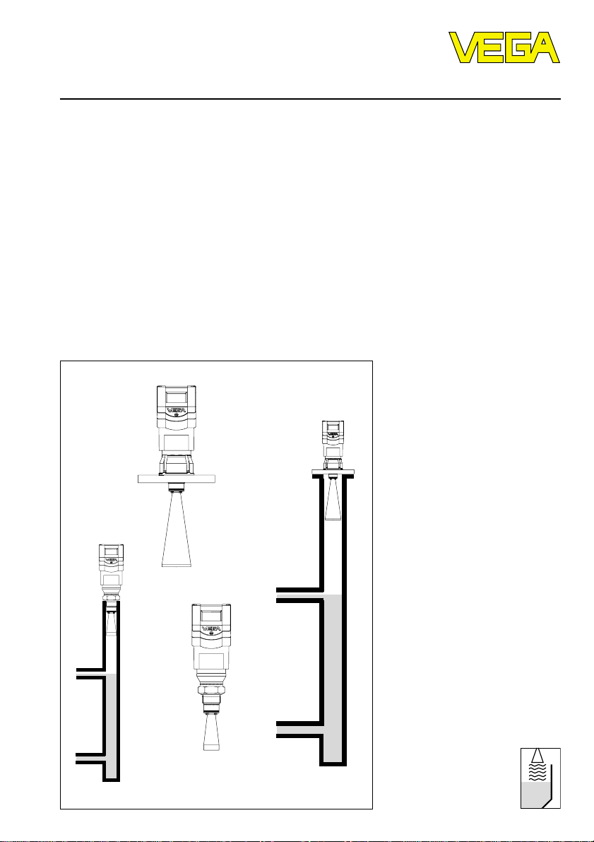
Quick start
In the majority of applications, the radar sensor displays the distance to the product
surface immediately after the power supply is
switched on. You only have to carry out the
empty and full adjustment so that at your
required empty and full distances, 4 mA and
20 mA, respectively, are outputted.
However, it is always useful, especially under
difficult measurement conditions (process
tanks, stirrers, filling stream, vessel installations), to carry out a sensor optimisation, see
chapter "6 Setup“.
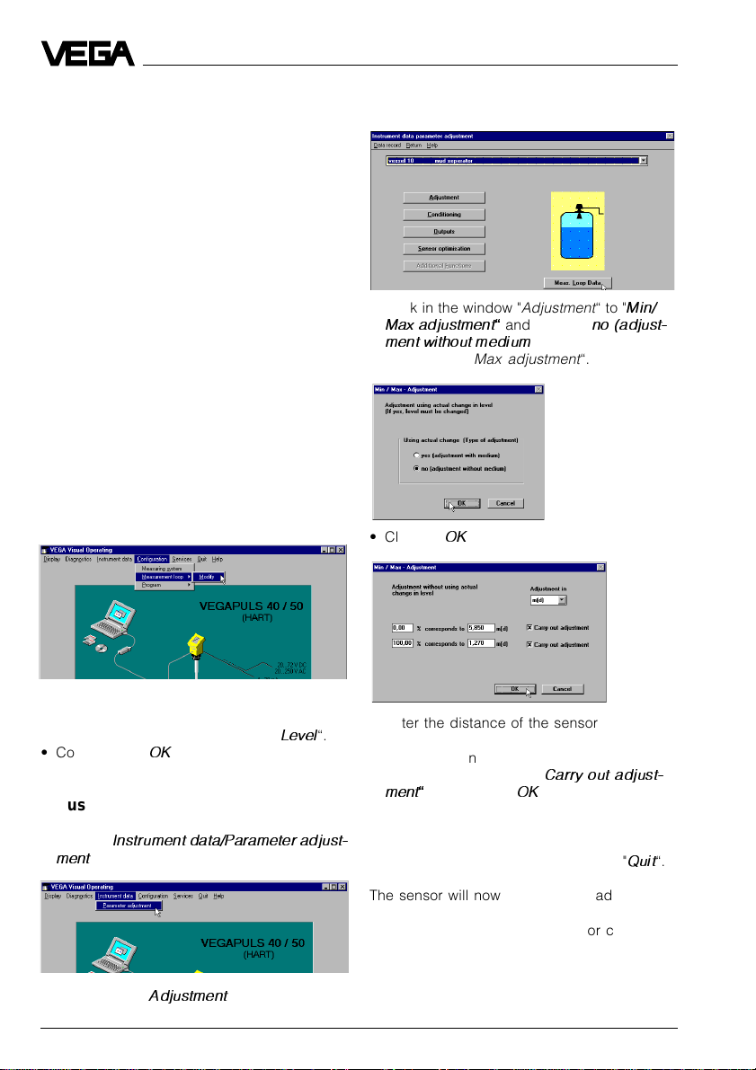
Quick start with the PC
Configuration
Start the adjustment software VVO ³2.60 with
the user level "
Planning
“.
• Click in the window "
Max adjustment and choose "
ment without medium)“ in the following
window „
Min/Max adjustment
Adjustment
“.
“ to "
no (adjust-
Quick start
Min/
• Click to …
… and enter a name for the measurement
loop.
• Choose under "
• Confirm with "OK“.
Application
“ e.g. "
Level
Adjustment
• Click to "
ment
• Then click to "
4 VEGAPULS 42 and 44 – 4 … 20 mA
Instrument data/Parameter adjust-
“.
Adjustment
“.
• Click to „OK“.
• Enter the distance of the sensor to the
“.
product surface at 0 % (empty) and at
100 % (full) in meters.
• Activate the two boxes "
ment and click to „OK“.
You are again in the window "
• Click in the window "
The sensor will now output at the adjusted
empty distance 4 mA and at the full distance
20 mA. In the example, the sensor calibrates
the span of 5.85 m to 1.27 m
to the signal range of 4 … 20 mA.
Carry out adjust-
Adjustment
Adjustment
“ to "
Quit
“.
“.
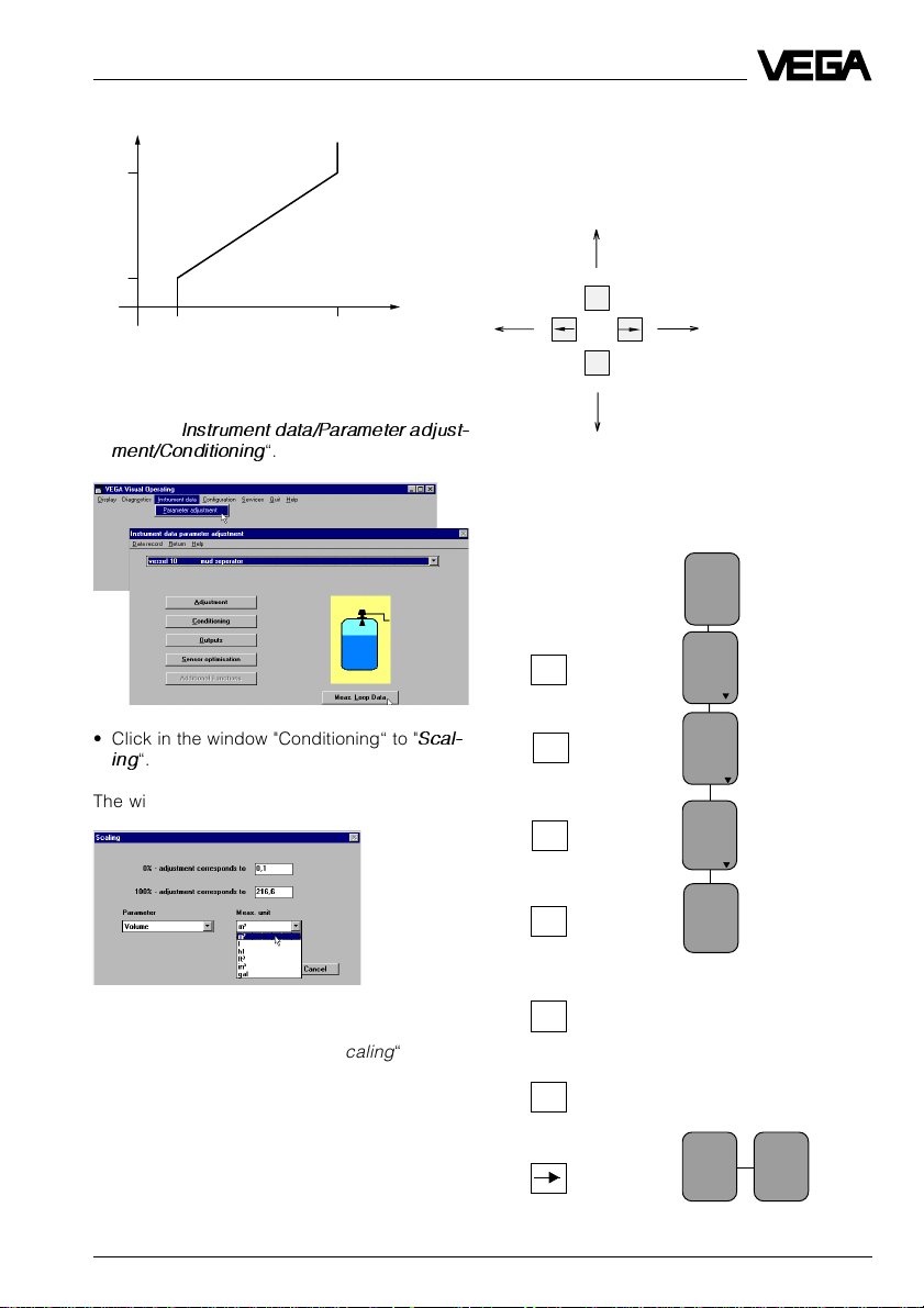
Quick start
m
5,85
1,27
mA
420
Scaling of the measured value display
• Click to "
ment/Conditioning
• Click in the window "Conditioning“ to "
ing
Instrument data/Parameter adjust-
“.
Scal-
“.
Quick start with adjustment module MINICOM
In the menu field you can move with these keys to the left, right,
top and bottom.
ESC
OK
Empty adjustment
Key Display text
Sensor
m(d)
4.700
Para-
OK
OK
meter
Adjustment
The window …
opens.
Allocate in the menu window "
Scaling
“ a
OK
OK
+
The display text flashes and
you can choose between
"feet“ and "m“.
w.out
medium
Adjustment
in
m(d)
(Min. adjustment)
physical quantity and the unit of measurement to the 0 % and 100 % values. Here you
inform the sensor, e.g. that at 0 % filling there
are still 0.1 m3 and at 100 % filling 216.6 m3 in
the vessel. The sensor display then indicates
0.1 m3 (0 %) for an empty vessel and
OK
Confirm the adjustment with
"OK“.
m(d)
0.0%
at
m (d)
XX.XXX
Adjustment
in
216.6 m3 (100 %) for a full vessel.
VEGAPULS 42 and 44 – 4 … 20 mA 5
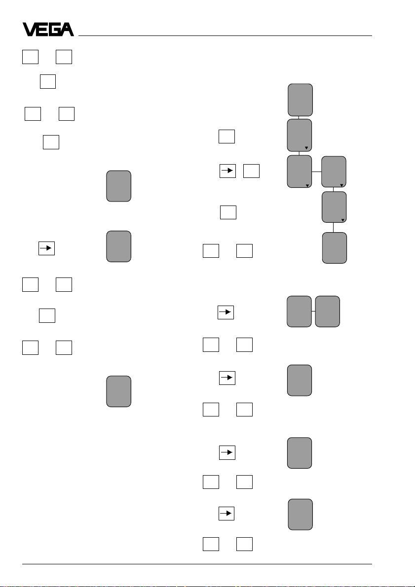
Quick start
+ –
or
Enter 0 %.
The 0 % value is allocated to
OK
the following distance and the
distance indication flashes.
+ –
or
OK
Enter the empty distance, e.g.
5.85 m.
The value pair 0 % and 5.85 m
is written into the sensor.
Full adjustment
+ –
or
OK
+ –
or
Enter 100 %.
The 100 % value is allocated
to the following distance and
the distance indication flashes.
Enter the distance with full
vessel, e.g. 1.27 m.
0.0%
at
m (d)
5,85
100.0%
at
m (d)
XX.XXX
(Max. adjustment)
Scaling of measured value display
Key Display text
Sensor
m(d)
4.700
Para-
OK
OK
OK
+ –
or
Enter the figure for the filling at 0 %, e.g.
0001.
+ –
or
Enter the figure of the 100 %
filling, e.g. 2166 for 216.6 m
meter
Adjustment
0 %
corres
ponds
XXXX
Conditioning
Scaling
0 %
corres
ponds
100 %
corres
ponds
XXXX
XXXX
3
Deci-
100.0%
at
m (d)
1,27
+ –
or
Enter the position of the
comma, so that 216.6 is dis-
mal
point
888.8
played.
prop.
to
Volume
+ –
or
+ –
or
6 VEGAPULS 42 and 44 – 4 … 20 mA
Choose the physical unit, e.g.
volume.
Unit
3
m
Choose the unit of measurement, e.g. m3.
Product description
1 Product description
VEGAPULS series 40 sensors are a newly
developed generation of extremely compact
radar sensors for high resolution and accuracy. They are characterised by very good
focussing features for applications in narrow
spaces. With very modest space requirements, they were developed for measuring
distances of 0 … 10 m/20 m and are the right
choice for standard applications such as
storage vessels, reservoirs and buffer tanks
as well as process tanks.
Due to small housing dimensions and process fittings, the compact sensors are an
obstrusive, and most of all, very reasonable
solution for your level measurement applications. With the integrated display they enable
high precision level measurements and can
be used for applications in which the advantages of non-contact measurement could
never before be realized.
VEGAPULS 40 radar sensors are perfectly
suited to two-wire technology. The supply
voltage and the output signal are transmitted
via one two-wire cable. As output or measuring signal, the instruments produce an analogue 4 … 20 mA output signal.
1.1 Function
Radio detecting and ranging: Radar.
VEGAPULS radar sensors are used for noncontact, continuous distance measurement.
The measured distance corresponds to a
filling height and is outputted as level.
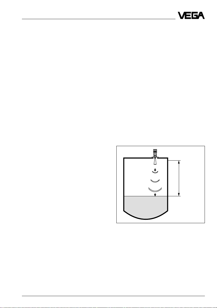
Measuring principle:
emission – reflection – reception
Tiny 24 GHz radar signals are emitted from
the antenna of the radar sensor as short
pulses. The radar impulses reflected by the
sensor environment and the product are
received by the antenna as radar echoes.
The running period of the radar impulses
from emission to reception is proportional to
the distance and hence to the level.
Meas.
distance
emission - reflection - reception
VEGAPULS 42 and 44 – 4 … 20 mA 7
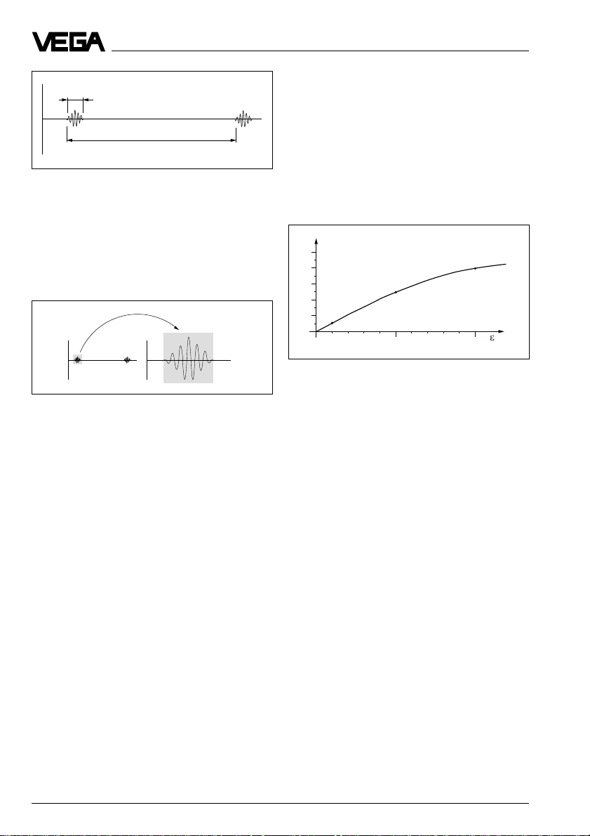
1 ns
278 ns
Pulse sequence
VEGAPULS radar sensors can accomplish
this through a special time transformation
procedure which spreads out the more than
3.6 million echo images per second in a slowmotion picture, then freezes and processes
them.
t
t
Product description
The radar impulses are emitted by the antenna system as pulse packages with a
pulse duration of 1 ns and pulse intervals of
278 ns; this corresponds to a pulse package
frequency of 3.6 MHz. In the impulse intervals, the antenna system operates as receiver. Signal running periods of less than
one billionth of a second must be processed
and the echo image must be evaluated in a
fraction of a second.
%
50
40
30
20
10
5 %
5
0
2
0
25 %
4 6 8 12 14 16 18
10
Reflected radar power dependent on the dielectric
constant of the measured product
40 %
20
r
Time transformation
Hence, it is possible for the VEGAPULS 40
radar sensors to process the slow-motion
pictures of the sensor environment precisely
and in detail in cycles of 0.5 to 1 second
without using time-consuming frequency
analysis (e.g. FMCW, required by other radar
techniques).
Virtually all products can be measured
Radar signals display physical properties
similar to those of visible light. According to
the quantum theory, they propagate through
empty space. Hence, they are not dependent on a conductive medium (as e.g. sound
waves in air), and spread out like light at the
speed of light. Radar signals react to two
basic electrical properties:
- the electrical conductivity of a substance
- the dielectric constant of a substance.
All products which are electrically conductive
reflect radar signals very well. Even slightly
conductive products ensure a sufficient reflection for a reliable measurement.
All products with a dielectric constant er of
more than 2.0 reflect radar impulses sufficiently (note: air has a dielectric constant er of
1).
The signal reflection increases with the conductivity or with the dielectric constant of the
product. Hence, virtually all products can be
measured.
With standard flanges of DN 50 to DN 250,
ANSI 2“ to ANSI 10“ or G 11/2 A and 11/2“ NPT,
the sensor antenna systems can be adapted
to the various measured products and measurement environments.
The high-quality materials can also withstand
extreme chemical and physical conditions.
The sensors deliver a stable, reproducible
analogue or digital level signal with reliability
and precision, and have a long useful life.
8 VEGAPULS 42 and 44 – 4 … 20 mA
Product description
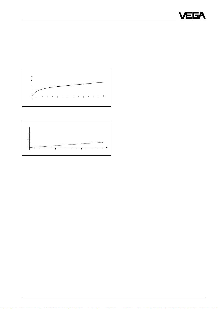
Continuous and reliable
Unaffected by temperature, pressure and
individual gas atmospheres, VEGAPULS
radar sensors are used for quick and reliable
continuous level measurement of various
products.
%
0,03
0,02
0,01
0
100 500 1000 1300 ˚C
0
0,018 %
Temperature influence: Temperature error absolutely
zero (e.g. at 500°C 0.018 %)
%
10
5
0,29 %
0
10
0
1,44 %
20 30 40 60
50
Pressure influence: Error with pressure increase very
low (e.g. at 50 bar 1.44 %)
VEGAPULS 40 sensors enable level measurement with radar in facilities where previously, due to high cost, it was completely out
of the question.
0,023 %
2,8 %
70 80 90 110 120 130 140
100
3,89 %
bar
1.2 Application features
Applications
• level measurement of liquids
• measurement also in vacuum
• all slightly conductive materials and all
substances with a dielectric constant > 2.0
can be measured
• measuring range 0 … 10 m (type 42).
measuring range 0 … 20 m (type 44).
Two-wire technology
• supply and output signal on one two-wire
cable (Loop powered)
• 4 … 20 mA output signal or HART® output
signal.
Rugged and abrasion proof
• non-contact
• high-resistance materials
Exact and reliable
• accuracy 0.05 %.
• resolution 1 mm.
• unaffected by noise, vapours, dusts, gas
compositions and inert gas stratification
• unaffected by varying density and temperature of the medium
• measurement in pressures up to 40 bar
and product temperatures up to 200°C
Communicative
• integrated display of measured value
• optional display module separate from
sensor
• adjustment with detachable adjustment
module, pluggable in the sensor or in the
external display
• adjustment from the PLC level with the PC
• adjustment with HART® handheld
Approvals
• CENELEC, ATEX, PTB, FM, CSA, ABS,
LRS, GL, LR, FCC.
VEGAPULS 42 and 44 – 4 … 20 mA 9
Product description
1.3 Adjustment
Each measuring situation is unique. For that
reason, every radar sensor needs some
basic information on the application and the
environment, e.g. which level means "empty“
and which level "full“. Beside this "empty and
full adjustment“, many other settings and
adjustments are possible with VEGAPULS
radar sensors.
The adjustment and parameter setting of
radar sensors are carried out with
- the PC
- the detachable adjustment module MINICOM
- the HART
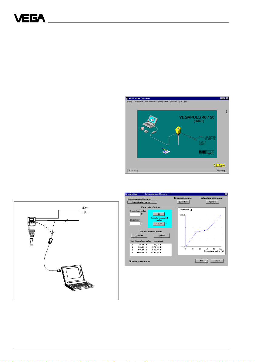
Adjustment with PC
The setup and adjustment of the radar sensors is generally done on the PC with the
adjustment program VEGA Visual Operating
(VVO) under Windows®. The program leads
quickly through the adjustment and parameter setting by means of pictures, graphics
and process visualisations.
®-
handheld
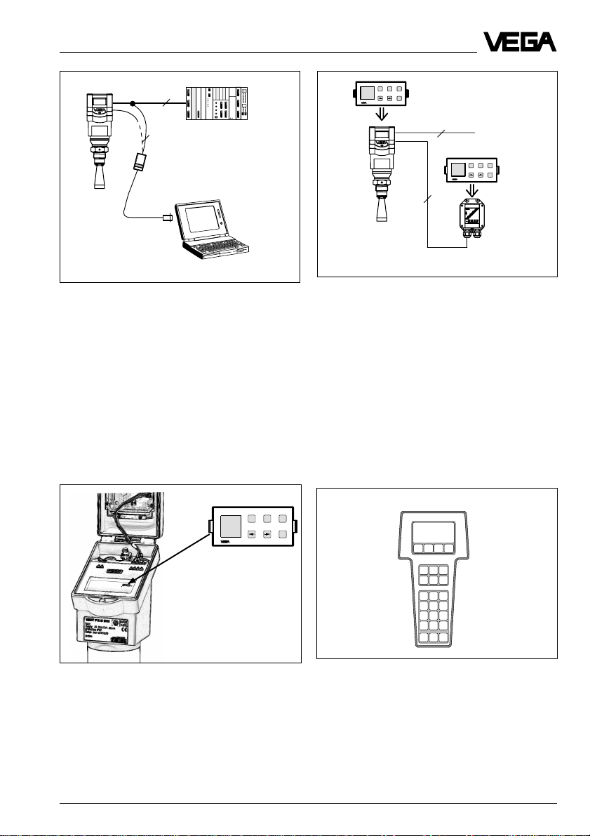
The PC can be connected at any location in
the system or on the signal cable. It is connected by means of the two-wire PC interface
converter VEGACONNECT 2 to the sensor or
the signal cable. The adjustment and parameter data can be saved with the adjustment
software on the PC and can be protected by
passwords. On request, the adjustments can
be quickly transferred to other sensors.
The adjustment program recognises the sensor type
2
4 ... 20 mA
2
Visualised input of a vessel linearisation curve
Adjustment with the PC on the analogue 4 … 20 mA
signal and supply cable or directly on the sensor
(four-wire sensor)
10 VEGAPULS 42 and 44 – 4 … 20 mA
Product description
ESC
+
-
Tank 1
m (d)
12.345
2
OK
PLC
2
Adjustment with the PC on the 4 … 20 mA signal and
supply cable or directly on the sensor (figure: a twowire sensor)
Adjustment with adjustment module
MINICOM
With the small (3.2 cm x 6.7 cm) 6-key adjustment module with display, the adjustment
can be carried out in clear text dialogue. The
adjustment module can be plugged into the
radar sensor or into the optional, external
indicating instrument.
Tank 1
m (d)
12.345
ESC
+
-
OK
2
4 ... 20 mA
ESC
+
-
Tank 1
m (d)
12.345
OK
4
Adjustment with detachable adjustment module. The
adjustment module can be plugged into the radar
sensor or the external indicating instrument VEGADIS
50.
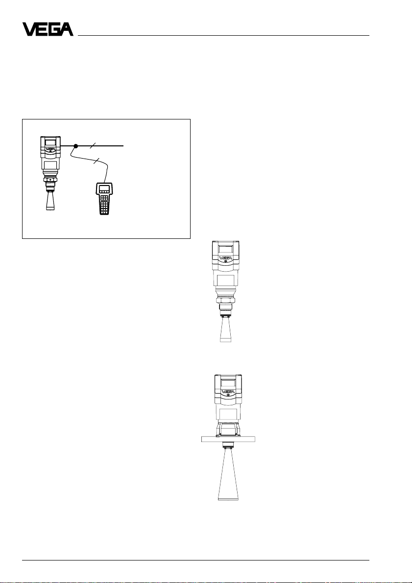
Adjustment with HART® handheld
Series 40 with 4 … 20 mA output signal can
also be adjusted with the HART® handheld.
A special DDD (Data Device Description) is
not necessary, so that the sensors can be
adjusted with the HART® standard menus of
the handheld.
HART Communicator
Detachable adjustment module MINICOM
HART® handheld
Unauthorised sensor adjustments can be
prevented by removing the adjustment module.
VEGAPULS 42 and 44 – 4 … 20 mA 11
Product description
For adjustment, just connect the HART® handheld to the 4 … 20 mA output signal cable or
insert the two communication cables of the
HART® handheld into the adjustment jacks on
the sensor.
2
4 ...20 mA
2
HART® handheld on the 4 … 20 mA signal cable
1.4 Antennas
The antenna is the eye of the radar sensor.
An uninitiated observer would probably not
realise how carefully the antenna geometry
must be adapted to the physical properties
of electromagnetic fields.
The geometrical form determines focal properties and sensitivity - the same way it determines the sensitivity of a unidirectional
microphone.
Four antenna systems are available for different applications and process requirements.
Horn antennas
Horn antennas focus the
radar signals very well.
Manufactured of 1.4435
(stainless steel) or Hastelloy C22, they are very rugged, and are physically as
well as chemically, resistant.
They are suitable for pressures up to 40 bar and for
product temperatures up to
150°C. The horn diameters
determine the focussing of
the radar signals. The an-
VEGAPULS 42
tenna gain grows stronger
with increasing diameter
(40, 48, 75, 95 mm). The
antenna gain represents
the ratio of emitted energy
to received echo energy.
VEGAPULS 44
12 VEGAPULS 42 and 44 – 4 … 20 mA
Product description
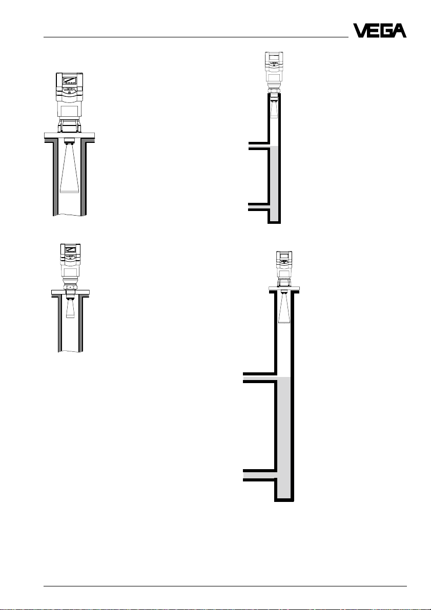
Pipe antennas
The pipe antennas on surge
or bypass tubes only form a
complete antenna system in
conjunction with a measuring
tube (which can also be
curved). The measuring tube
acts as a conductor for
radar signals. The running
period of the radar signals
changes in the tube and is
dependent on tube diameter.
The tube inner diameter must
be programmed in the sensor so that it can take the
altered running time into
account and deliver precise
level signals. Pipe antennas
are especially suitable for
processes with intense
product movements or products with low dielectric constant.
The antennas are characterised by very high gain. High
reliability can be achieved
even with products with very
poor reflective features.
VEGAPULS 42 on bypass tube
VEGAPULS 44 on bypass tube
VEGAPULS 42 and 44 – 4 … 20 mA 13
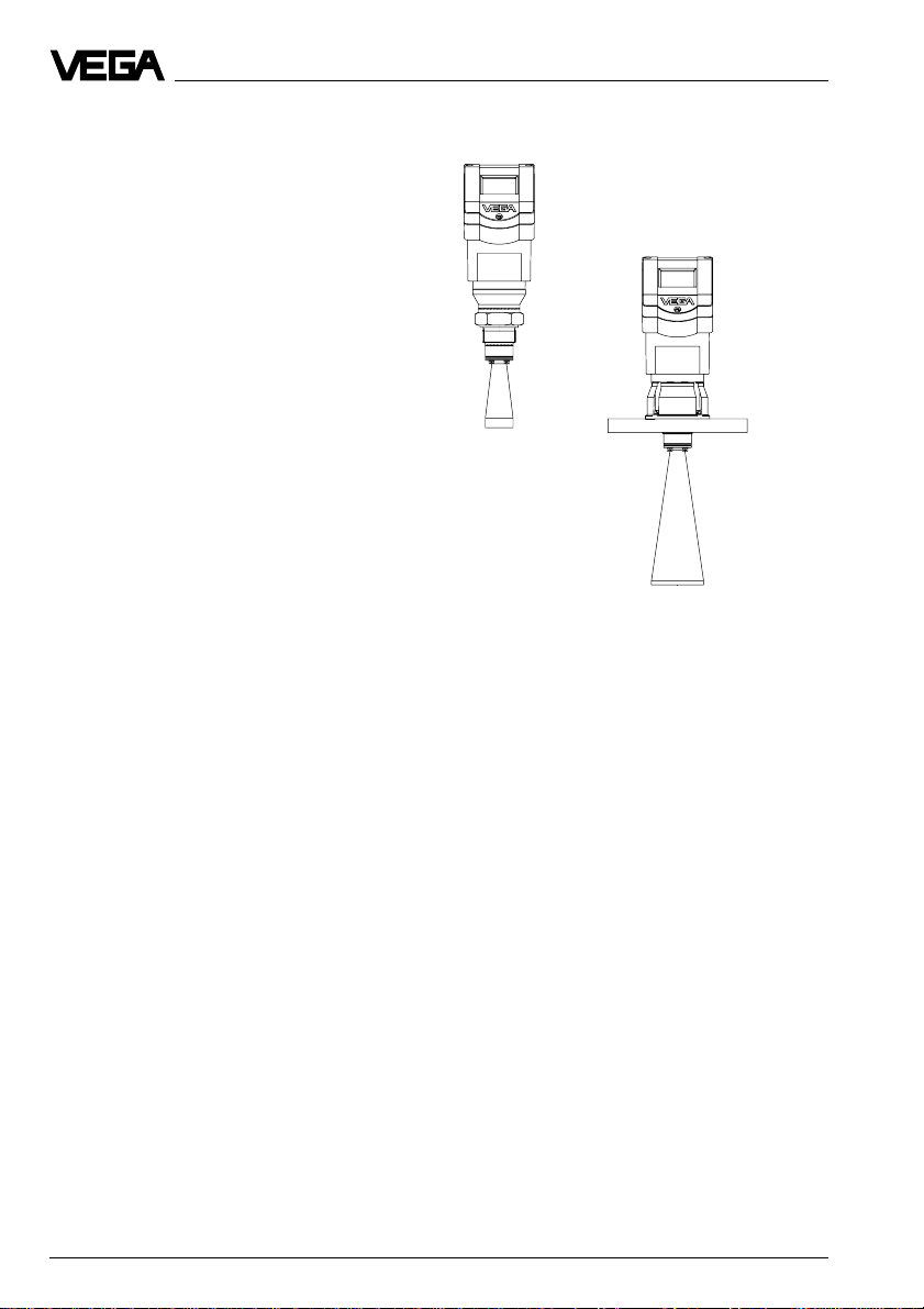
2 Types and versions
Types and versions
Series 40 sensors are manufactured in two
basic versions, VEGAPULS 42 and VEGAPULS 44.
VEGAPULS 42 are characterised by a
G 11/2 A or 11/2“ NPT thread as process fitting.
These sensors are equipped as standard
versions with a ø 40 mm horn as antenna.
VEGAPULS 44 are characterised by a DIN or
ANSI flanges as process fitting. In standard
version they are manufactured with DN 50,
80, 100 and 150 as well as with ANSI 2“, 3“,
4“ and 6“. The bigger flanges come
equipped with respectively larger antenna
horns (ø 48, 75 and 95 mm).
Generally: The bigger the antenna horn, the
better the focussing characteristics, and the
better the antenna gain. This ensures that
even a weak product echo can be detected
reliably as level echo.
VEGAPULS 42
VEGAPULS 44
14 VEGAPULS 42 and 44 – 4 … 20 mA
Types and versions
2.1 Survey
General features
• Application preferably for liquids in storage tanks, reservoirs and process vessels with
increased accuracy requirements.
• Measuring range 0 … 10 m or 0 … 20 m.
• Ex approved in zone 1 (IEC) or zone 1 (ATEX) classification
EEx ia [ia] IIC T6.
• Integrated display of measured values.
Survey
VEGAPULS …
42 44
Signal output
– active (4 … 20 mA) ••
– passive (4 … 20 mA loop powered) ••
Voltage supply
– two-wire technology (voltage
supply and signal output
via one two-wire cable) ••
– four-wire technology (voltage
supply separate from the signal
cable) ••
Process fitting
– G 11/2 A; 11/2“ NPT •–
– DN 50; ANSI 2“–•
– DN 80; ANSI 3“–•
– DN 100; ANSI 4“–•
– DN 150; ANSI 6“–•
Adjustment
– PC ••
– adjustment module in the sensor ••
– adjustment module in external
indicating instrument ••
– HART® handheld ••
Measuring range max.
–ø 40 mm horn 10 m –
–ø 48 mm horn 15 m 15 m
–ø 75 mm horn 20 m 20 m
–ø 95 mm horn 20 m 20 m
VEGAPULS 42 and 44 – 4 … 20 mA 15

Type code
Types and versions
PS 42 .XX X X X XXX X X
K - Plastic housing PBT, M20 x 1,5 cable entry
N - Plastic housing PBT,
1
/2“ NPT cable entry
A - Aluminium housing, M20 x 1,5 cable entry
D - Aluminium housing, 1/2“ NPT cable entry in Exd connection
housing
V - Seal of the antenna system: Viton
A - Seal of the antenna system: Kalrez
G - Process fitting G 11/2 A
N - Process fitting 11/2“ NPT
ABC- Pr ocess fitting DN 50 PN 16
BBE- Process fitting DN 80 PN 16
CBG- Process fitting DN 100 PN 16
DBG- Process fitting DN 150 PN 16
ARC- Process fitting ANSI 2“ 150 psi
BRE- Process fitting ANSI 3“ 150 psi
CRG- Process fitting ANSI 4“ 150 psi
DRG- Process fitting ANSI 6“ 150 psi
YYY- Process fitting on request
X - without display
A - with integrated display
X - without adjustment module MINICOM
B - with adjustment module MINICOM (mounted)
B - 20 … 72 V DC; 20 … 250 V AC; 4 … 20 mA, HART
(four-wire)
D - Two-wire (loop powered), 4 … 20 mA, HART
®
®
E - Supply via signal conditioning instrument
G - Segment coupler for Profibus PA
XX - FTZ (standard telecommunication approval Germany)
AX - Approval in Ex-Zone 1, EEx ia IIC T6
CX - Approval in Ex-Zone 0, EEx ia IIC T6
BX - Approval in Ex-Zone 1 (Exd connection housing)
DX - Approval in Ex-Zone 0 (Exd connection housing)
Type 42:with screw-on process fitting
Type 44: instrument series with flange process fitting
PS: Series 40 radar sensors
16 VEGAPULS 42 and 44 – 4 … 20 mA

2
4 … 20 mA
-
+
1)
4
Types and versions
2.2 Configuration of measuring systems
A measuring system consists of a sensor
with a 4 … 20 mA signal output and a module
that evaluates and further processes the
level-proportional current signal.
On the following pages you will see various
measuring systems, each consisting of a
different instrument configuration (several
also with signal conditioning).
Measuring systems in two-wire technology:
• 4 … 20 mA shown without processing unit,
(bottom)
• 4 … 20 mA on active PLC,
• 4 … 20 mA in Ex area on active PLC
(page 18)
(Ex ia
page 20, Ex d PAGE 23)
• 4 … 20 mA in Ex area on passive PLC,
(page 21)
• 4 … 20 mA in Ex area on VEGADIS 371 Ex
indicating instrument,
(page 22)
Measuring systems in four-wire technology:
• 4 … 20 mA shown without signal conditioning instrument,
(non Ex page 19, Ex d
page 23)
Measuring systems with VEGAPULS 42 or 44 connected to any 4 … 20 mA signal
processing unit
• Two-wire technology (loop powered), supply and output signal via one two-wire cable.
• Output signal 4 … 20 mA (passive).
• Optional external indicating instrument with analogue and digital display (can be mounted
up to 25 m separated from the sensor).
• Adjustment with PC, HART® handheld or the adjustment module MINICOM (can be plugged
into the sensor or into the external indicating instrument VEGADIS 50).
VEGADIS 50
1)
If the resistance of the processing systems
connected to the 4 … 20 mA signal output is less
than 250 W, a resistor must be connected to the
connection cable during adjustment to get a loop
resistance of 250 W.
The digital adjustment signal would otherwise be
severely damped or short-circuited due to
insufficient resistance of the connected
processing system. Communication with the PC
would not be ensured.
VEGAPULS 42 and 44 – 4 … 20 mA 17
VEGACONNECT 2
HART® handheld

Types and versions
Measuring system with VEGAPULS 42 or 44 on active PLC
• Two-wire technology, supply by active PLC.
• Output signal 4 … 20 mA (passive).
• Measured value display integrated in the sensor.
• Optional external indicating instrument (can be mounted up to 25 m separated from the
sensor in Ex area).
• Adjustment with PC, HART® handheld or the adjustment module MINICOM (can be plugged
into the sensor or into the external indication instrument).
VEGADIS 50
4
2 2
2
VEGACONNECT 2
1)
If the resistance of the processing systems
connected to the 4 … 20 mA signal output is less
than 250 W, a resistor must be connected to the
connection cable during adjustment to get a loop
resistance of 250 W.
The digital adjustment signal would otherwise be
severely damped or short-circuited due to
insufficient resistance of the connected processing
system. Communication with the PC would not be
ensured.
4 … 20 mA
passive
2
1)
2)
PLC (active)
HART® handheld
2)
4 … 20 mA passive means that the sensor
3)
consumes a level-dependent current of
4 … 20 mA. The sensor reacts electrically like a
varying resistor (consumer) to the PLC.
3)
Active means that the PLC powers the passive
sensor as voltage source.
18 VEGAPULS 42 and 44 – 4 … 20 mA

Types and versions
Measuring system with VEGAPULS 42 or 44 in four-wire technology
• Four-wire technology, supply and output signal via two separate two-wire cables.
• Output signal 4 … 20 mA active.
• Optional external indicating instrument with analogue and digital display (can be mounted
up to 25 m separated from the sensor).
• Adjustment with PC, HART® handheld or adjustment module MINICOM (can be plugged into
the sensor or into the external indicating instrument VEGADIS 50).
• Max. resistance on the signal output (load) 500 W.
VEGADIS 50
2
4
1)
³ 250 W
VEGACONNECT 2
2
2
2
-
+
4 … 20mA
2)
(active)
HART® handheld
1)
If the resistance of the processing systems
connected to the 4 … 20 mA signal output is less
than 250 W, a resistor must be connected to the
connection cable during adjustment to get a loop
2)
4 … 20 mA active means that the sensor delivers
a level-dependent current of 4 … 20 mA (source).
The sensor reacts electrically to the processing
system (e.g. display) like a current source.
resistance of 250 W.
The digital adjustment signal would otherwise be
severely damped or short-circuited due to
insufficient resistance of the connected
processing system. Communication with the PC
would not be ensured.
VEGAPULS 42 and 44 – 4 … 20 mA 19

Types and versions
Measuring system with VEGAPULS 42 or 44 via separator in Ex area on active PLC
• Two-wire technology (loop powered), supply via the signal line of the PLC; output signal
4 … 20 mA (passive).
• Separator transfers the non intrinsically safe PLC circuit to the intrinsically safe circuit, so
that the sensor can be used in Ex zone 1 or Ex zone 0.
• Optional external indicating instrument with analogue and digital display (can be mounted
up to 25 m separated from the sensor).
• Adjustment with PC, HART® handheld or adjustment module MINICOM (can be plugged into
the sensor or into the external indicating instrument VEGADIS 50).
VEGADIS 50
4
Zone 0 or
Zone 1
Ex area
EEx ia
Non Ex area
Separator (e.g. Stahl)
(see "3.2 Approvals“)
2
VEGACONNECT 2
1)
4 … 20 mA
passive
2
2)
2
2
PLC (active)
HART® handheld
1)
If the resistance of the processing systems
connected to the 4 … 20 mA signal output is less
than 250 W, a resistor must be connected to the
connection cable during adjustment to get a loop
resistance of 250 W.
2)
4 … 20 mA passive means that the sensor
consumes a level-dependent current of
4 … 20 mA. The sensor reacts electrically like a
varying resistor (consumer) to the PLC. The PLC
operates active, i.e. as current or voltage source.
The digital adjustment signal would otherwise be
severely damped or short-circuited due to
insufficient resistance of the connected
processing system. Communication with the PC
would not be ensured.
20 VEGAPULS 42 and 44 – 4 … 20 mA

Types and versions
Measuring system with VEGAPULS 42 or 44 via separator (Smart-Transmitter) on passive PLC
• Two-wire technology (loop powered), intrinsically safe ia supply via the signal cable of the
separator for operation of the sensor in Ex zone 1 or Ex zone 0.
• Output signal sensor 4 … 20 mA passive.
Output signal separator 4 … 20 mA active.
• Optional external indicating instrument with analogue and digital display (can be mounted
up to 25 m separated from the sensor).
• Adjustment with PC, HART® handheld or adjustment module MINICOM (can be plugged into
the sensor or into the external indicating instrument VEGADIS 50).
VEGADIS 50
4
Zone 0 or
Zone 1
Ex area
EEx ia
Non Ex area
Separator (e.g. VEGATRENN 149 Ex see
"3.2 Approvals“)
-
+
2
4 … 20 mA
(active)
2
2
VEGACONNECT 2
1)
2)
PLC (passive)
3)
HART® handheld
1)
If the resistance of the processing systems
connected to the 4 … 20 mA signal output is less
than 250 W, a resistor must be connected to the
connection cable during adjustment to get a loop
resistance of 250 W.
The digital adjustment signal would otherwise be
severely damped or short-circuited due to
insufficient resistance of the connected
processing system. Communication with the PC
2)
4 … 20 mA active means that the separator
delivers a level-dependent current of 4 … 20 mA
(source). The separator reacts electrically to the
PLC like a current source.
3)
4 … 20 mA passive means that the PLC consumes
a level-dependent current of 4 … 20 mA. The PLC
reacts electrically like a varying resistor
(consumer) to the PLC.
would not be ensured.
VEGAPULS 42 and 44 – 4 … 20 mA 21

Types and versions
Measuring system with VEGAPULS 42 or 44 on VEGADIS 371 Ex indicating
instrument with current and relay output
• Two-wire technology (loop powered), intrinsically safe ia supply via the signal cable of the
VEGADIS 371 Ex indicating instrument for operation of the sensor in Ex zone 1 or Ex
zone 0.
• Optional external indicating instrument with analogue and digital display (can be mounted
up to 25 m separated from the sensor).
• Adjustment with PC, HART® handheld or adjustment module MINICOM (can be plugged into
the sensor or into the external indicating instrument VEGADIS 50).
VEGADIS 50
4
Zone 0 or
Zone 1
Ex area
EEx ia
Non Ex area
2
2
2
VEGACONNECT 2
1)
4 ... 20 mA
(passive)
-
+
VEGADIS
371 Ex
(see "3.2 Approvals“)
HART® handheld
Relay
0/4 … 20 mA
(active)
1)
If the resistance of the processing systems
connected to the 4 … 20 mA signal output is less
than 250 W, a resistor must be connected to the
connection cable during adjustment to get a loop
resistance of 250 W.
The digital adjustment signal would otherwise be
severely damped or short-circuited due to
insufficient resistance of the connected
processing system. Communication with the PC
would not be ensured.
22 VEGAPULS 42 and 44 – 4 … 20 mA

Types and versions
VEGAPULS 42 Ex or 44 Ex (loop powered) with pressure-tight encapsulated
terminal compartment on active PLC
• Two-wire technology, supply via the signal cable of active PLC on Exd connection housing
for operation in Ex zone 1 (VEGAPULS …Ex) or Ex zone 0 (VEGAPULS …Ex0).
• Output signal 4 … 20 mA (passive).
• Measured value display integrated in the sensor.
• Optional external indicating instrument (can be mounted up to 25 m separated from the
sensor in Ex area).
• Adjustment with PC, HART® handheld or adjustment module MINICOM (can be plugged into
the sensor or into the external indicating instrument VEGADIS 50).
Ex area
VEGADIS 50 Ex
4
1)
If the resistance of the processing systems
Non Ex-area
2
VEGACONNECT 2
2
2
connected to the 4 … 20 mA signal output is less
than 250 W, a resistor must be connected to the
connection cable during adjustment to get a loop
resistance of 250 W.
The digital adjustment signal would otherwise be
severely damped or short-circuited due to
insufficient resistance of the connected
processing system. Communication with the PC or
the HART® handheld would not be ensured.
4 … 20 mA
2)
passive
2
PLC (active)
HART® handheld
2)
4 … 20 mA passive means that the sensor
consumes a level-dependent current of
4 … 20 mA. The sensor reacts electrically like a
varying resistor (consumer) to the PLC.
VEGAPULS 42 and 44 – 4 … 20 mA 23

Technical data
VEGAPULS 42 Ex or 44 Ex with pressure-tight encapsulated connection
compartment in four-wire technology
• Four-wire technology, supply and output signal via two separate two-wire cables for use in
Ex zone 1 (VEGAPULS …Ex) or Ex zone 0 (VEGAPULS …Ex0).
• Output signal 4 … 20 mA (active).
• Optional external indicating instrument with analogue and digital display (can be mounted
up to 25 m separated from the sensor in Ex area).
• Adjustment with PC, HART® handheld or adjustment module MINICOM (can be plugged into
the sensor or into the external indicating instrument VEGADIS 50).
• Load max. 500 W.
Ex area
VEGADIS 50 Ex
4
1)
If the resistance of the processing systems
Non Ex area
VEGACONNECT 2
2
2
connected to the 4 … 20 mA signal output is less
than 250 W, a resistor must be connected to the
connection cable during adjustment to get a loop
resistance of 250 W.
The digital adjustment signal would otherwise be
severely damped or short-circuited due to
insufficient resistance of the connected
processing system. Communication with the PC or
the HART® handheld would not be ensured.
2
-
+
2
> 250 Ω
2)
4 … 20 mA active means that the sensor delivers
4 … 20mA
2)
active
HART® handheld
a level-dependent current of 4 … 20 mA (source).
The measuring signal of the sensor reacts
electrically to the processing system (e.g. display)
like a current source.
24 VEGAPULS 42 and 44 – 4 … 20 mA

Technical data
3 Technical data
3.1 Technical data
Power supply
Supply voltage
- four-wire sensor 24 V DC (20 … 72 V DC)
- two-wire sensor 24 V DC (14 … 36 V DC)
- two-wire Ex ia sensor 24 V DC (14 … 29 V DC)
- two-wire Ex d ia sensor 24 V DC (20 … 36 V DC)
Current consumption
- four-wire sensor max. 60 mA
- two-wire sensor max. 22.5 mA
Power consumption
- four-wire sensor max. 200 mW, 1.2 VA
- two-wire sensor 55 … 810 mW
Load
- four-wire sensor max. 500 Ohm
- two-wire sensor see diagram
230 V AC (20 … 250 V AC), 50/60 Hz
fuse 0.2 A TR
Ω
975
1000
900
max. load Non Ex
max. voltage limit
Non Ex and
Ex d ia sensors
Adjustment
resistor
(HART® and
VEGACONNECT)
720
670
250
800
600
400
700
500
300
200
100
max. load Ex ia
0
15
14
19,5
20
max. load Ex d ia
Non Ex and Ex ia
25,5
25
Exd ia
29
min. voltage limit when using the HART
adjustment resistor:
- Non Ex and Ex ia sensors
- Ex d ia sensors
30 35
36
V
max. voltage limit
Ex ia sensors
®
VEGAPULS 42 and 44 – 4 … 20 mA 25

Technical data
Measuring range
1)
VEGAPULS 42 (ø 40 mm horn)
- optional 0 … 10 m
ø 48 mm horn 0 … 15 m
ø 75, 95 mm horn 0 … 20 m
VEGAPULS 44
- DN 50, ANSI 2“ 0 … 15 m
- DN 80, 100, ANSI 3“, 4“, 6“ 0 … 20 m
Standpipe measurement in DN 50 standpipe
- VEGAPULS 42 0 … 20 m
- VEGAPULS 44 0 … 20 m
Standpipe measurement in DN 100 standpipe
- VEGAPULS 42 0 … 20 m
- VEGAPULS 44 0 … 20 m
Output signal
4 … 20 mA current signal in two or four-wire technology
Integration time 0 … 999 seconds (adjustable)
Load
-4 … 20 mA two-wire
Non Ex: max 975 W
Ex d ia: max. 720 W
Ex ia: max. 670 W
-4 … 20 mA four-wire 500 W
Two-wire technology 4 … 20 mA:
The analogue 4 … 20 mA output signal (measuring signal) is transmitted together with the
power supply via one two-wire cable.
Four-wire technology 4 … 20 mA:
Separate power supply. The analogue 0/4 … 20 mA output signal (measuring signal) is led
in a cable separate from the supply voltage.
Measured value display (optional)
Liquid-crystal display
- in the sensor scalable output of measured values as graph
and digital value
- powered externally from the sensor scalable output of measured values as graph
and digital value. Measured value display can
be mounted up to 25 m away from the sensor.
Adjustment
- PC and adjustment software VEGA Visual Operating
- adjustment module MINICOM
- HART® handheld
1)
Min. distance of the antenna to the medium 5 cm
26 VEGAPULS 42 and 44 – 4 … 20 mA

Technical data
Accuracy
2)
(typical values under reference conditions, all statements relate to the nominal measuring
range)
Characteristics linear
Deviation in characteristics including
linearity, reproducibility and
hysteresis (determined acc. to the
limit point method) < 0.05 %
Linearity better than 0.05 %
Average temperature coefficient of the
zero signal 0.06 %/10 K
Resolution in general max. 1 mm
Resolution of the output signal 0.01 % or 1 mm
Characteristics
1)
(typical values under reference conditions, all statements relate to the nominal measuring
range)
Min. span between
full and empty > 10 mm (recommended > 50 mm)
Frequency 24 GHz technology
Intervals
- two-wire sensor (4 … 20 mA) 1 s
- two-wire sensor (digital) 0.6 s
- four-wire sensor 0.5 s
Beam angle (at –3 dB)
- VEGAPULS 42 22°
optional 18°, 10° and 8° when using bigger coupling
horn deviating from nominal size
- VEGAPULS 44
DN 50, ANSI 2“ 18°
DN 80, ANSI 3“ 10°
DN 100, ANSI 4“ 8°
DN 150, ANSI 6“ 8°
Adjustment time (response time) > 1 s (depending on parameter setting)
Influence of the process temperature not measurable at 0 bar; at 5 bar 0.004 %/10 K;
at 40 bar 0.03 %/10 K
Influence of the process pressure 0.0265 %/bar
Adjustment time
Radar emitted power (average) 0.717 µW
Received average emitted power
2)
3)
> 1 s (depending on parameter setting)
- distance 1 m 0.5 … 1.5 nW pro cm² (0.5 … 1.5 x 10⁻⁹W/cm²)
- distance 5 m 0.02 … 0.6 nW pro cm²
1)
Similar to DIN 16 086, reference conditions acc. to IEC 770, e.g.
temperature 15°C … 35°C; moisture 45 % … 75 %; pressure 860 mbar … 1060 mbar
2)
The adjustment time (also actuating time, response time or adjustment period) is the time the sensor
requires to output the correct level (with max. 10% deviation) after a quick level change.
3)
Average emitted power reaching an object (electromagnetic energy) per cm² directly in front of the antenna.
The received emitted power depends on the antenna version and the distance.
VEGAPULS 42 and 44 – 4 … 20 mA 27
 Loading...