

VEGA Grieshaber KG MIPR61, MIPT61 Users Manual
Operating Instructions
VEGAMIP R61
Receiving unit
- Relay
Document ID:
35786
Radar

Contents
Contents
1 About this document
1.1 Function. . . . . . . . . . . . . . . . . . . . . . . . . . . . . . . . . .
1.2 Target group . . . . . . . . . . . . . . . . . . . . . . . . . . . . . .
1.3 Symbolism used . . . . . . . . . . . . . . . . . . . . . . . . . . . .
2 For your safety
2.1 Authorised personnel . . . . . . . . . . . . . . . . . . . . . . . .
2.2 Appropriate use . . . . . . . . . . . . . . . . . . . . . . . . . . . .
2.3 Warning about misuse . . . . . . . . . . . . . . . . . . . . . . .
2.4 General safety instructions . . . . . . . . . . . . . . . . . . . .
2.5 CE conformity . . . . . . . . . . . . . . . . . . . . . . . . . . . . .
2.6 Radio approval for USA/Canada . . . . . . . . . . . . . . . .
2.7 Environmental instructions. . . . . . . . . . . . . . . . . . . . .
3 Product description
3.1 Configuration . . . . . . . . . . . . . . . . . . . . . . . . . . . . . .
3.2 Principle of operation . . . . . . . . . . . . . . . . . . . . . . . .
3.3 Packaging, transport and storage . . . . . . . . . . . . . . .
3.4 Accessories and replacement parts . . . . . . . . . . . . . .
4 Mounting
4.1 General instructions . . . . . . . . . . . . . . . . . . . . . . . . .
4.2 Mounting instructions . . . . . . . . . . . . . . . . . . . . . . . .
5 Connecting to power supply
5.1 Preparing the connection . . . . . . . . . . . . . . . . . . . . .
5.2 Connection procedure. . . . . . . . . . . . . . . . . . . . . . . .
5.3 Wiring plan, single chamber housing . . . . . . . . . . . . .
4
4
4
5
5
5
5
6
6
6
7
7
9
10
12
12
19
19
21
6 Setup
6.1 Adjustment elements . . . . . . . . . . . . . . . . . . . . . . . .
6.2 Adjustment. . . . . . . . . . . . . . . . . . . . . . . . . . . . . . . .
7 Maintenance and fault rectification
7.1 Maintenance . . . . . . . . . . . . . . . . . . . . . . . . . . . . . .
7.2 Rectify malfunctions . . . . . . . . . . . . . . . . . . . . . . . . .
7.3 Exchange the electronics . . . . . . . . . . . . . . . . . . . . .
7.4 How to proceed in case of repair. . . . . . . . . . . . . . . .
8 Dismounting
8.1 Dismounting steps . . . . . . . . . . . . . . . . . . . . . . . . . .
8.2 Disposal . . . . . . . . . . . . . . . . . . . . . . . . . . . . . . . . .
9 Supplement
9.1 Technical data . . . . . . . . . . . . . . . . . . . . . . . . . . . . .
9.2 Dimensions . . . . . . . . . . . . . . . . . . . . . . . . . . . . . . .
2 VEGAMIP R61 • - Relay
22
23
28
28
29
29
30
30
31
34
35786-EN-100531

Contents
Safety instructions for Ex areas
Please note the Ex-specific safety information for installation and
operation in Ex areas. These safety instructions are part of the
operating instructions manual and come with the Ex-approved
instruments.
35786-EN-100531
VEGAMIP R61 • - Relay 3
1 About this document
1 About this document
1.1 Function
This operating instructions manual provides all the information you
need for mounting, connection and setup as well as important
instructions for maintenance and fault rectification. Please read this
information before putting t he instrument into operation and keep this
manual accessible in the immediate vicinity of the device.
1.2 Target group
This operating instructions manual is directed to trained qualified
personnel. The contents of this manual should be made available to
these personnel and put into practice by them.
1.3 Symbolism used
Information, tip, note
This symbol indicates helpful additional information.
Caution: If this warning is ignored, faults or malfunctions can
result.
Warning: If this warning is ignored, injury to persons and/or serious
damage to the instrument can result.
Danger: If this warning is ignored, serious injury to persons and/or
destruction of the instrument can result.
Ex applications
This symbol indicates special instructions for Ex applications.
l List
The dot set in front indicates a list with no implied sequence.
à Action
This arrow indicates a single action.
1 Sequence
Numbers set in front indicate successive steps in a procedure.
4 VEGAMIP R61 • - Relay
35786-EN-100531

2 For your safety
2 For your safety
2.1 Authorised personnel
All operations described in this operating instructions manual must be
carried out only by trained specialist personnel authorised by the plant
operator.
During work on and with the device the required personal protective
equipment must always be worn.
2.2 Appropriate use
The VEGAMIP 61 is a sensor for level detection.
You can find detailed information on the application range in chapter
"Product description".
Operational reliability is ensured only if the instrument is properly used
according to the specifications in the operating instructions manual as
well as possible supplementary instructions.
2.3 Warning about misuse
Inappropriate or incorrect use of the instrument can give rise to
application-specific hazards, e.g. vessel overfill or damage to system
components through incorrect mounting or adjustment.
2.4 General safety instructions
This is a state-of-the-art instrument complying with all prevailing
regulations and guidelines. The instrument must only be operated in a
technically flawless and reliable condition. The operator is responsible
for the trouble-free operation of the instrument.
During the entire duration of use, the user is obliged to determine the
compliance of the necessary occupational safety measures with the
current valid rules and regulations and also take note of new
regulations.
The safety instructions in this operating instructions manual, the
national installation standards as well as the valid safety regulations
and accident prevention rules must be observed by the user.
For safety and warranty reasons, any invasive work on the device
beyond that described in the operating instructions manual may be
carried out only by personnel authorised by the manufacturer. Arbitrary
conversions or modifications are explicitly forbidden.
The safety approval markings and safety tips on the device must also
be observed.
35786-EN-100531
VEGAMIP R61 • - Relay 5

2 For your safety
Any changes or modifications not expressly approved by the party
responsible for compliance could void the user's authority to operate
the equipment.
This device complies with Part 15 of the FCC rules. Operation is
subject to the following two conditions: (1) This device may not cause
harmful interference, and (2) this device must accept any
interference received, including interference that may cause
undesired operation.
The emitting frequencies of the sensors depend on the model, but are
all in the K band range. The low transmitting power lies far below the
internationally permitted limit value. When the instrument is used
correctly, it presents no danger to human health. It may be operated
without restriction outside of closed vessels.
2.5 CE conformity
The device fulfills the legal requirements of the applicable EC
guidelines. By attaching the CE mark, VEGA provides a confirmation
of successful testing. You can find the CE conformity declaration in the
download area of
www.vega.com.
2.6 Radio approval for USA/Canada
FCC Note according to 15.21:Any changes or modifications not
expressly approved by the party responsible for compliance could void
the user's authority to operate the equipment.
FCC S tatement for Part 15 (FCC allows the placement in the
manual only when the label is too small to place the statement):
this device complies with Part 15 of the FCC rules. Operation is
subject to the following two conditions: (1) This device may not cause
harmful interference, and (2) this device must accept any interference
received, including interference that may cause undesired operation.
IF Class A or Class B digital device or peripheral FCC Compliance
Statement §15.105, Class A or B must be included in the manual .
FCC-Statement for Part 15:This device complies with Part 15 of the
FCC rules. Operation is subject to the following two conditions: (1)
This device may not cause harmful interference, and (2) this device
must accept any interference received, including interference that may
cause undesired operation.
2.7 Environmental instructions
Protection of the environment is one of our most important duties. That
6 VEGAMIP R61 • - Relay
is why we have introduced an environment management system with
the goal of continuously improving company environmental protection.
The environment management system is certified according to DIN
EN ISO 14001.
Please help us fulfil this obligation by observing the environmental
instructions in this manual:
l Chapter "Packaging, transport and storage"
l Chapter "Disposal"
35786-EN-100531

3 Product description
3.1 Configuration
3 Product description
Type label
Serial number
Scope of delivery
The type label contains the most important data for identification and
use of the instrument:
l Article number
l Serial number
l Technical data
l Article numbers, documentation
With the serial number, you can access the delivery data of the
instrument via
www.vega.com, "VEGA Tools" and "serial number
search". In addition to the type label outside, you can also find the
serial number on the inside of the instrument.
The serial number on the type label of the instrument allows you to
have the order data, operating instructions manuals, sensor data for
the service DTM as well as the test certificate (depending on the
instrument) displayed via
www.vega.com, "VEGA Tools" and "serial
number search".
The scope of delivery typically consists of the following components.
l Point level sensor VEGAMIP R61 (receiving unit)
l Documentation
- this operating instructions manual
- Supplementary instructions manual "Plug connector for level
sensors" (optional)
- Ex-specific "Safety instructions" (with Ex versions)
- if necessary, further certificates
l The corresponding emitting unit VEGAMIP T61 is described in a
separate operating instructions manual.
l
3.2 Principle of operation
Application area
35786-EN-100531
VEGAMIP R61 • - Relay 7
VEGAMIP 61 is a microwave barrier for level detection.
It is designed for industrial use in all areas of process technology and
can be used in bulk solids and liquids.
Typical applications are overfill and dry run protection. With an
operating distance of 100 m, VEGAMIP 61 can be used, for example,
in bulk solids silos with large diameters. Thanks to its simple and
rugged measuring system, VEGAMIP 61 is virtually unaffected by the
process and the chemical and physical properties of the medium.
VEGAMIP 61 can be also used for detection of vehicles and ships or
for material recognition on conveyor belts.
33
5
4
5
21
3 Product description
It works even under extremely difficult conditons, such as different
granulation sizes, contamination, extreme filling noise, high temperatures, strong dust generation or a brasive products.
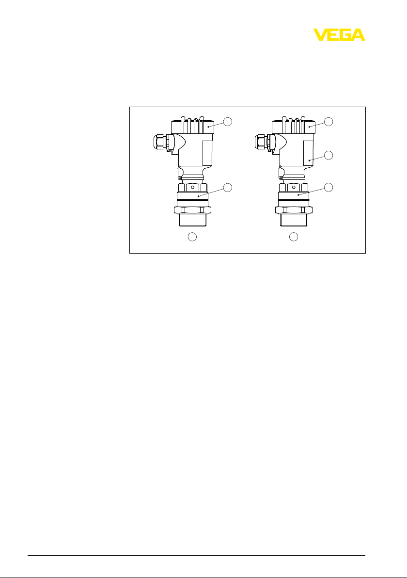
The VEGAMIP 61 consists of the following components.
Fig. 1: VEGAMIP 61 with plastic housing
1 Emitting unit VEGAMIP T61
2 Receiving unit VEGAMIP R61 with control electronics
3 Housing cover
4 Housing with control electronics
5 Process fitting
8 VEGAMIP R61 • - Relay
35786-EN-100531

1 2
3
4
3 Product description
Several antenna versions are available for different applications.
Fig. 2: Antenna versions
1 Encapsulated horn antenna with PTFE cover
2 Plastic encapsulated antenna with PP cover
3 Horn antenna
4 VEGAMIP 61 with angled antenna extension
Functional principle
The emitting unit transmits a focused microwave signal via horn
antenna to the receiving unit on the opposite side. If there is medium
between emitting and receiving unit, the signal is damped. This
change is detected by the built-in electronics module and converted
into a switching command.
3.3 Packaging, transport and storage
Packaging
Transport
Transport inspection
35786-EN-100531
VEGAMIP R61 • - Relay 9
Your instrument was protected by packaging during transport. Its
capacity to handle normal loads during transport is assured by a test
according to DIN EN 24180.
The packaging of standard instruments consists of environmentfriendly, recyclable cardboard. For special versions, PE foam or PE foil
is also us ed. Dispose of the packaging material via specialised
recycling companies.
Transport must be carried out under consideration of the notes on the
transport packaging. Nonobservance of these instructions can cause
damage to the device.
The delivery must be checked for completeness and possible transit
damage immediately at receipt. Ascertained transit damage or
concealed defects must be appropriately dealt with.

3 Product description
Storage
Storage and transport
temperature
Protective cover
Flanges
Up to the time of installation, the packages must be left closed and
stored according to the orientation and storage markings on the
outside.
Unless otherwise indicated, the packages must be stored only under
the following conditions:
l Not in the open
l Dry and dust free
l Not exposed to corrosive media
l Protected against solar radiation
l Avoiding mechanical shock and vibration
l Storage and transport temperature see chapter "Supplement -
Technical data - Ambient conditions"
l Relative humidity 20 … 85 %
3.4 Accessories and replacement parts
The protective cover protects the sensor housing against soiling and
intense heat from solar radiation.
You will find additional information in the supplementary instructions
manual "Protective cover" (Document-ID 34296).
Flanges are available in different versions according to the following
standards: DIN 2501, EN 1092-1, ANSI B 16.5, JIS B 2210-1984,
GOST 12821-80.
You will find additional information in the supplementary instructions
manual "Flanges according to DIN-EN-ASME-JIS" (Document-ID
31088).
Electronics module
The electronics module VEGAMIP R61 is a replacement part for
microwave barriers of VEGAMIP series 60.
You will find additional information in the following operating
instructions manual:
l "Electronics module VEGAMIP R61 (receiving unit)" (Document-ID
36428)
10 VEGAMIP R61 • - Relay
35786-EN-100531

3 Product description
Mounting adapter
With high process temperatures exceeding 80 °C, you have to use a
mounting adapter for the emitting and receiving unit. The mounting
adapter can be only used with the encapsulated horn antenna with
PTFE cover.
Fig. 3: VEGAMIP 61 with high temperature mounting adapter
35786-EN-100531
VEGAMIP R61 • - Relay 11

4 Mounting
4 Mounting
4.1 General instructions
Screwing in
Suitability for the pro-
cess conditions
Moisture
With instruments with threaded process fitting, suitable tools must be
applied for tightening the hexagon.
Warning:
The housing must not be used to screw the instrument in! Applying
tightening force can damage internal parts of the housing.
Make sure that all parts of the instrument exposed to the process, in
particular the antenna, seal and process fitting, are suitable for the
existing process conditions. These include above all the process
pressure, process temperature as well as the chemical properties of
the medium.
You can find the specifications in chapter "Technical data" or on the
type label.
Use the recommended cables (see chapter "Connecting to power
supply") and tighten the cable gland.
You can give your instrument additional protection against moisture
penetration by leading the connection cable downward in front of the
cable entry. Rain and condensation water can thus drain off. This
applies mainly to outdoor mounting as well as installation in areas
where high humidity is expected (e.g. through cleaning processes) or
on cooled or heated vessels.
4.2 Mounting instructions
Switching point
12 VEGAMIP R61 • - Relay
If possible, install VEGAMIP 61 in a position where a high signal
damping by the medium is expected.
35786-EN-100531
 Loading...