

Page 1

U2020
Application Guide
Page 2

Vega U2020 Application Guide
This guide provides information for configuring U2020 systems with various numbers of channels. Block diagrams
and basic equipment lists are provided for systems with from four to sixteen channels. Other useful application and
configura t ion information is also included.
Important Notes
1. Each MC-2020 series multicoupler can power to up to four attached receivers through its BNC antenna cables.
The MC-2020 power supply has a capacity of 2.5 amperes, more than enough for four receivers and the
multicoupler itself. It is NOT necessary to use the wall-type power supplies for the receivers when they are
connected to the output of a MC-2020 multicoupler. This usually considerably simplifies the installation of a
U2020 system.
WARNING
Because dc power is present at the output connectors of the MC-2020, unused outputs SHOULD NOT be
terminated with 50 ohms. For the same reason, MC-2020 series mulitcouplers SHOULD NOT be used with
receivers other than the R-2020. Serious damage to the receiver, and in some cases to the multicoupler, can
result.
2. The original MC-2020 multicoupler covered the 746 -782 MHz frequency range used by the "A" and "B"
versions of the U2020 system. The newer MC-2020A multicoupler covers the full 672 to 782 MHz frequency
range, making it compatible with the newer "C", "D", "E" and "F" frequency ranges for the U2020, as well as
with the original "A" and "B" ranges. If a U2020 installation includes ANY systems in the newer "C", "D", "E"
and "F" frequency ranges, the MC-2020A multicoupler MUST be used, and not the original MC-2020.
3. Early MC-2020 multicouplers used 2.5 mm power connectors, the same size as for the R-2020 receiver. In some
instances, users attempted to power MC-2020s and the attached R-2020s from one of the small wall-type power
supplies. This resulted in system failure and overheating of the power supply. Recently produced MC-2020s and
all MC-2020As use a 2.1 mm power connector, preventing this problem.
If a replacement power supply is required for a MC-2020; please specify the connector size when ordering. (If
the plug on a wall-type power supply fits the power connector on the MC-2020, a replacement with the 2.5 mm
connector is required. If it does not fit, a 2.1 mm power connector is needed.)
2
Page 3

Vega U2020 Application Guide
Application Tips
The MC-2020 and MC-2020A are supplied with eight 24" (60 cm) BNC RF cables for connecting the multicoupler
output to four R-2020 receivers. Unless remote antennas will be used, no additional RF cables will be required.
The MC-2020 and MC-2020A are not supplied with antennas. Generally, installations that use multicouplers will
require remote antennas. If the use of whip antennas is acceptable, the whips supplied with one of the R-2020s can be
used. Note that the antennas can be converted from right-angle to straight whips by loosening the hex set screw on the
side of the antenna body, removing the antenna element, reinserting it into the hole on the end of the body, then
retightening the set screw.
The R-2020 receiver and MC-2020 series multicouplers include a feature that allows the antennas to be mounted on
either the front or the rear of the unit. These units are normally shipped with the connectors on the rear panel. If
relocation to the front panel is desired (to permit use of the supplied whip antennas when the eq uipment is rack
mounted, for example), proceed as follows.
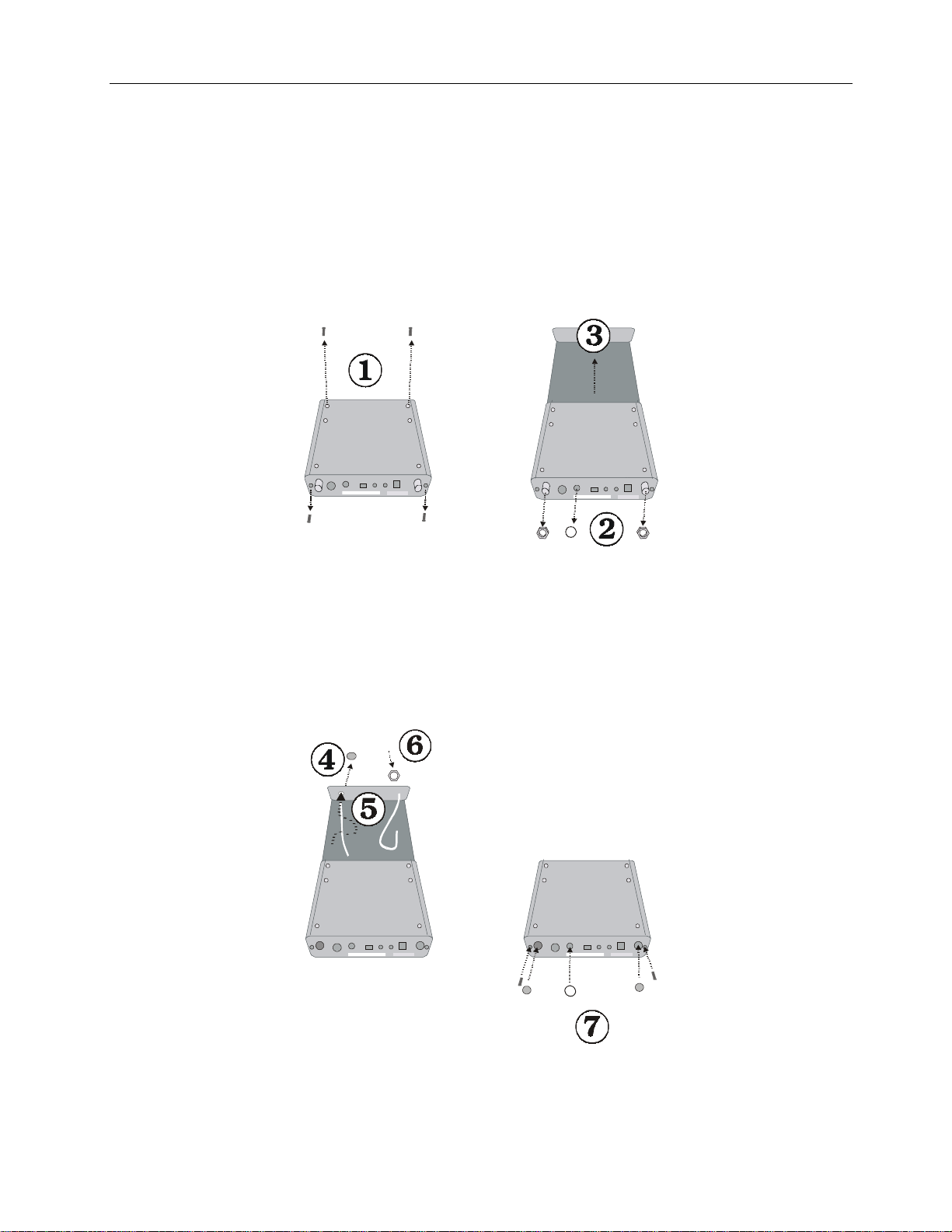
To move antennas to the front of the multicoupler
1. Remove the screws attaching the bottom cover of the unit and detach the cover.
2. With a 5/8" (16 mm) socket wrench, remove the hex nuts attaching the connector to the multicoupler rear
panel.
3. Gently push out the round plastic cover hole covers on the front panel of the unit.
4. Remove the antenna connectors from the rear panel of the unit and install them in the front panel of the unit.
Make certain that the internal antenna cables do not lie down directly on the multicoupler circuitry, as this
will affect performance.
5. Reinstall the connector hex nut and lockwasher, then gently tighten the nut. Do not use excessive force, as
this can crack the panel of the unit.
6. Repeat for the other connector.
7. Push round plastic cover hole covers into the hole where the antennas were before and reinstall the bottom
cover of the unit.
3
Page 4
Vega U2020 Application Guide
To move antennas to the front of the receiver
1. Using a Phillips-head screwdriver, remove the two bottom screws (bottom panel closest to the front of the
receiver) and the two screws on the rear panel as shown below.
2. Using a 5/8” (16 mm) socket wrench, unscrew the antenna hex nuts. Then using a small pair of pliers, gently
unscrew the round serrated audio-output connector nut.
3. Gently slide the PCB out.
4. Pop out the antenna plugs in the front of the receiver.
5. Carefully move the antenna connectors to the front panel and insert the connectors through the holes. Make
certain that the internal antenna cables do not lie down directly on the receiver circuitry, as this will affect
performance.
6. Screw the hex nuts and lock washers back on (being careful not to use excessive force) and slide the PCB back
into the case. Then reattach the two bottom screws.
7. Pop the plugs into the antenna holes in the rear panel and reattach the audio-output nut and small screws to the
rear panel.
4
Page 5

Vega U2020 Application Guide
Rack Mounting Kit
A dual rack mounting kit for the R-2020, MC-2020 and MC-2020A, model RK-2020, is available. Complete
instructions for mounting receivers and multicouplers are included with the RK-2020. Note that there will be an
unfilled hole remaining when a odd number of receivers and multicouplers are mounted. A decorative blank filler
panel, the PB-2020, is available for use in this situation.
Antenna Orientation
When using whip antennas, best performance is usually obtained when the antennas are arranged in a “V” orientation.
In this configuration one antenna will be approximately 45 degrees clockwise from vertical, and the other
approximately 45 degrees counterclockwise from vertical.
-45 45
Remote Antennas
Using directly-attached whip antennas for rack mounted U2020 systems can create a number of performance
problems, including poor range and unnecessary interference. This is especially likely when metal cabinets are used
or when a considerable amount of equipment is being rack mounted.
At the very minimum, the antennas should be relocated to the front panel of the receivers or multicoupler (see
instructions on pages 3 and 4) and the rack turned so that the front of rack faces the area where the wireless transmitter
will be used. When using multiple receivers, the antennas should never be allowed to touch each other.
Performance
5
Page 6

Vega U2020 Application Guide
In most cases, remote antennas are preferable when U2020 systems are rack mounted. Vega offers several appropriate
UHF antennas, including the AN-722, AN-723 and AN-725. The whip antennas supplied with the receivers can also
be used remotely, PROVIDED that an appropriate ground plane is provided. See the illustration below. Consult the
Vega factory for recommendations for other suitable ground plane configurations.
R-2020 Antenna
(straight configuration)
UG-492
feed thru
connector
16 by 16” (40 x 40 cm)
metal plate
Centered
0.50”
(13mm)
hole
Lockwasher and nut
for UG-492
Plate may be painted
except for the area
beneath the UG-492 flange,
lockwasher and nut
BNC
Antenna
cable
NOTICE:
Simply connecting a whip antenna to the end of a coaxial cable results in an extremely inefficient antenna which will
almost always greatly reduce the usable range of the wireless systems. Do not use this arrangement.
Using Remote Antennas
Vega's AN-700 series antennas are provided with 10 to 15 foot (3 to 4.5 M) RF cables. In situations where longer
cables are necessary, extension cables can be used. However, there are a considerable number of technical
considerations involved, particularly when cable lengths over about 30 feet (10 M) are needed. Discussion of all of
the various issues involved in this situation are well beyond the scope to this guide. Consult the Vega factory for
additional information. A wireless applications guide, which includes an e xtensive discussion regarding antennas and
antenna cables, is available from Vega. Users of Vega wireless systems can obtain a copy of this document by
contacting Technical Support at the Vega factory.
6
Page 7

Vega U2020 Application Guide
U2020 System Block Diagrams and Equipment Lists
This information may be helpful to you when planning various size systems. Call Vega for larger system
diagrams. Please feel free to duplicate as required.
Four-Up Systems consist o f:
4 U2020 Systems of choice
1 MC-2020 Multicoupler
3 RK-2020 Rack Kits
1 PB-2020 Blank Panel
2 AN-700 Series antennas of choice
Six-Up Systems consist of:
6 U2020 Systems of choice
2 MC-2020 Multicoupler
4 RK-2020 Rack Kits
2 AN-700 Series antennas of choice
Eight-Up Systems consist of:
8 U2020 Systems of choice
3 MC-2020 Multicoupler
6 RK-2020 Rack Kits
1 PB-2020 Blank Panel
2 AN-700 Series antennas of choice
Ten-Up Systems consist of:
10 U2020 Systems of choice
3 MC-2020 Multicoupler
7 RK-2020 Rack Kits
1 PB-2020 Blank Panel
2 AN-700 Series antennas of choice
Twelve-Up Systems consist of:
12 U2020 Systems of choice
4 MC-2020 Multicoupler
8 RK-2020 Rack Kits
2 AN-700 Series antennas of choice
Sixteen-Up Systems consist of:
16 U2020 Systems of choice
5 MC-2020 Multicoupler
11 RK-2020 Rack Kits
1 PB-2020 Blank Panel
2 AN-700 Series antennas of choice
7
Page 8

Four-Up Systems consist o f:
Vega U2020 Application Guide
MC-2020 or MC-2020A
Supplied 24” (60 cm)
BNC cables
R-2020 receivers
Six-Up Systems consist of:
8
Page 9

Eight-Up Systems consist of:
Vega U2020 Application Guide
Ten-Up Systems consist of:
9
Page 10

Twelve-Up Systems consist of:
Vega U2020 Application Guide
10
Page 11

Sixteen-Up Systems consist of:
Vega U2020 Application Guide
11
Page 12

Vega U2020 Application Guide
(g
)
BT-2020 Lavalier Microphone Connections
Many different manufacturer’s microphones may be connected to BT-2020s. Use the following information as a
guide only.
Ceramic chip capacitors
100 - 270 PFD
Rear View
Positive (+) Bias
Shield
Phone: 626-442-0782 • Toll-Free: 800-877-1771 • Fax: 626-444-1342
FaxBack: 626-444-2017 • Toll-Free FaxBack: 800-274-2017
round
Vega
9900 East Baldwin Place • El Monte, California 91731-2294
www.vegawireless.com
Audio with 10 k-ohm
resistor to ground
Audio with positive bias
through10 k-ohm resistor
12
Page 13

Vega Microphone Connection Data: Miniature XLR (TINI "Q-G")
(For Vega Models: T-16, T-17, T-25, T-37, Ranger Transmitters, and BT-2020)
Manufacturer Model Vega Model # Pin #1 Pin #2 Pin #3 Pin #4 Notes
AKG C67, C567 — Shield — White — 2
Audio Technica AT803, 831 — Red/Wh — Yel/Bk Shield 1, 2
Audio Technica ATM71 HM-177X Red — Yellow Shield 2
Beyer MCE5.9 — Inner Sh. — Green Shield 2
Beyer MCE10 — Inner Sh. — Green Shield 2
Crown GLM-100/E LM-202X Red — White Shield
Countryman Various — Red — White Shield 4
Electro-Voice CO-90 — White — Red Shield
Electro-Voice CO-100 LM-208X White — Red Shield 2
Electro-Voice CS-200 LM -209X White — Red Shield 2
Electro-Voice CO2 CO2EX Pink — White Shield 2
PSC Millimic — Red — Shield
Sanken COS-11 — Black — White Shield 2
Sennheiser MKE 2 LM-204X Red — White Shield 2, 7, 8
Sennheiser 40 Red — White Shield 2, 7, 8
Shure 838 113X Red — Black Shield 2, 4
Shure SM83 Red — Black Shield 2, 4
Shure SM84 Red — Black Shield 4
Sonotrim Various — — White — Shield 10
Sony ECM-44_PT LM-201X Red — White Shield 2, 6
Sony ECM-50 PS — Red — White Shield 2
Sony ECM-55_PT — Red — White Shield 2, 6
Sony ECM-66_PT — Red — White Shield 2, 6
Sony ECM-77_PT — Red — White Shield 2, 6
Tram TR-50 (Neg) — Shield — White — 1
Tram TR-50 PS — — White — Shield 1
Vega RSX-7 LM -210X Red — White Shield 2
Vega RSX-11 LM -206X — Red — Shield 2
Vega RSX-12 LM -203X Red/Wh — Yel/Blk Shield 1, 2
General Pos 2 wire — — Audio — Shield
General Pos 3 wire — + Bias — Audio Shield
General Neg 2 wire — Shield — Audio —
General Neg 3 wire — Shield Audio — – Bias
General Hi Output
Dynamic
Pin Function — — + Bias
ww
— — — Wire #1 Wire #2/
Shield
(6-9 v)
+ Bias
thru 10 kW
10 kW to
Ground (Audio)
Ground
3, 5
Notes
1) Manufacturer not consistent with wire color code assignments and biasing
arrangements. Some units may have different colors and may require other
bias connections.
2) These microphones are frequently RF sensitive. A small monolithic bypass
chip capacitor (220 to 560 pF) may be required from the signal lead to
ground, or from the bias lead to ground, or both.
3) These transmitters are optimized for use with lavalier electret microphones.
Low output dynamic microphones may not drive the transmitter fully.
4) Some microphones require an electronic equalizing circuit for proper
response. They will operate properly but may not sound exactly like the
wired version.
5)
A Vega 114X adapter cable allows many types of wired handheld mics to
be used with these transmitters. Low output mics may require a step-up
transformer (Shure A97A, or equal)
6)
Wired (i.e., non-“PT”) versions of these mics may not use same color code.
7) These mics have very high output and may not use same color code.
8) These mics have very high output and may overdrive the transmitter. If you
experience difficulties, please consult your dealer or the Vega factory.
9) Some late model Crown PZM mics are not wireless compatible.
098- 0306F
www.vegawireless.com
 Loading...