

Page 1
Operating Instruction
Ex-separator type 3041
5 6 7 8
MTL 3000 Series
MEASUREMENT TECHNOLOGY LTD.
Level and Pressure
125mA
FUSE
1 2 3 4
out
in
Page 2
Application and function
Ex-separator type 3041 for intrinsically safe power
supply of two-wire transmitters in Ex-areas.
Transmitters such as e.g. VEGABAR and VEGADIF,
with a current output of 4 … 20 mA, are used in
conjunction with the separator in Ex-areas. The
separator separates Ex-areas from not-Ex-areas,
meets Ex ia IIC and is characterized by three general
functions:
- intrinsically safe power supply of a two-wire
transmitter in Ex-areas
- transmission of the 4 … 20 mA current signal
- galvanic isolation of the three circuits (power
supply, converter and output circuit).
The power supply of 20 … 35 V DC is connected to
terminals 3 and 4..
Operating instruction
This current signal in the trnasmitter circuit is
transmitted floating by the separator via terminals 1
and 2 to the connected signal conditioning instrument.
Due to the complete galvanic isolation of the three
circuits, the circuits can be earthed at one end to the
earth potential in any position. Problems in the signal
transmission to processing systems by earthing
problems and current loss are thereofre solved.
„Intrinsically safe“ identifies a protection by which
current and voltage of a circuit are limited such that
the energy released in case of shortcircuits and
switching procedures is not sufficient to ignite explosive mixtures.
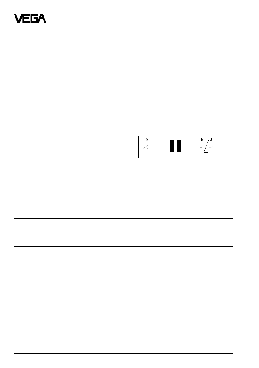
On terminals 5 and 6 the separator delivers an
intrinsically safe, floating DC voltage to power a twowire transmitter. The transmitter converts a parameter,
e.g. a pressure into a 4 ... 20 mA current signal proportional to the parameter.
Transmitters
(Sensors)
Technical data and dimensions
Power supply (terminals 3 and 4)
Voltage 20 … 35 V DC
Power consumption max. 2,8 W
Current consumption max. 125 mA
Transmitter circuit (Ex-area, terminal 5 and 6)
Signal transmission range 4 … 20 mA
Characteristic for intrinsic safety (Ex ia IIC) U
No-load voltage 28 V
Full load voltage 17,5 V
Line impedance max. in Ohm Z
Output circuit (Not-Ex-area, terminal 1 and 2)
Signal transmission areas 4 … 20 mA
Inner resistor > 1 MΩ
Load resistor max. 800 Ω
Linearity error at 20°C < 20 µA
Temperature drift < 1 µA/°C
Residual ripple < 10 µA peak – peak
= 28 V; I
max
R
≥ 300 Ω; PK ≤ 2,6 W
I
17,5 V – (min. transmitter operating voltage)
= ––––––––––––––––––––––––––––––––––––––––––––
max
p
≤ 93 mA
K
0,023 A
out
in
Signal
conditioning
instrument
2 Ex-separator type 3041
Page 3

Operating instruction
Further data
Galvanically isolated separation between the circuits
up to a voltage of 250 V AC
Operating temperature -20°C … +60°C
Storage and transport temperature -40°C … +80°C
Max. cross-section area of conductor 4 mm
Mounting in not-Ex-area 35 x 7,5 mm rail or screwable on two
Fuse 125 mA slow-blow, 5 mm ø x 20 mm
Weight 200 g
Dimensions W x H x D = 25 x 75 x 110 mm
2
extractable clips (therefore remove clip springs)
C-rail
5 6 7 8
75
110
3
Mounting and electrical connection
Please note:
• The DIN and VDE-regulations.
• The connection lines from the separator and
transmitter must be permanently marked.
• Do not mount the separator in hazardous areas
(not-Ex-area).
• Only connect one transmitter to a separator.
• Earth the cable screenings only at one cable end..
Mounting
Plug the separator on the C-rail or screww to the base
on the extractable clips.
Connection
Connect the transmitter located in the Ex-area to the
blue coloured terminals 5 (+) and 6 (–) of the
transmitter. If strong electromagnetic inter ferences
have to be expected, screened cable must be used.
Connect the output circuit to the signal conditioning
instrument to the terminals 1 (+) and 2 (–). Now
connect the voltage supply with 20 … 35 V DC to
terminals 3 (+) and 4 (–).
The separator now powers the transmitter with
intrinsically safe voltage and transmits the 4 … 20 mAsignal floating from the transmitter to the signal
conditioning instrument.
FUSE
1 2 3 4
25
Ex-area
Not-Exarea
Power supply
20…35VDC
82
Transmitter
p
+
–
5 6 7 8
FUSE
1 2 3 4
–
+–
+
Signal
conditioning
instrument
out
in
Ex-separator type 3041 3
Page 4

VEGA Grieshaber KG
Am Hohenstein 113
D-77761 Schiltach
Phone (0 78 36) 50 - 0
Fax (0 78 36) 50 - 201
Fax (0 78 36) 50 - 203
Safety information
The described module must only be inser ted and
operated as described in this operating instruction.
Please note that other action can cause damage for
which VEGA does not take responsibility.
ISO 9001
Technical data subject to alterations 2.19 722 / Febr. ’96
 Loading...