

Page 1
1756 Octal Relay
Service Manual
1756 OCTAL RELAY
RELAY 1
RELAY 2
RELAY 3
RELAY 4
RELAY 5
RELAY 6
RELAY 7
RELAY 8
098-0354
Rev A.
Page 2

2 Vega
TABLE OF CONTENTS
1. Forward ........................................2
2. General ........................................2
3. Installation ......................................3
4. Connections ....................................6
5. Operation.......................................8
6. Theory of operation ...............................8
Vega Fax Library ..................................10
Suggestions or Comments ..........................10
Warranty (Limited) .................................10
1756 Parts List....................................11
Specifications ....................................12
1. Forward
This manual is intended for use by experienced technicians familiar with similar types
of equipment. All the information required for installation, operation and servicing is
included.
The manual is divided into sections for easy reference. Each section, although related,
may be read independently without first reading the previous section. Any special
equipment will be included at the end of the manual.
2. General
The Vega Model 1756 Relay Card is a general purpose card that provides a reliable
means of remotely controlling a variety of customer specified devices. The card was
intentionally designed to be flexible, incorporating E point jumpers which allow the
user to operate the card without alteration, to perform various switching functions, or by
changing the jumper configuration, to allow for user defined special functions. It plugs
into a Tellabs, Type 10 or equivalent open frame rack and can be used in conjunction
with any remote control console.
2.1 Standard Features
2.2 Optional Features
"
Six double pole double throw relays, with direct wiring to the card edge connector
suitable for phone line pair switching.
"
Two double pole double throw relays, with one pole directly wired to the card
edge connector, capable of switching signals.
"
Front panel LED indicators that illuminate when the corresponding relay is
energized.
"
Low power input for active relay drive signals.
"
12 Vdcoperation.
"
Jumper selected switched high or switched low inputs.
"
Relays 5 and 6 can have one pole isolated from the card edge connector by
removal of 0 ohm resistor jumpers, and installing jumpers arranged for unique
switching operation.
"
Relays 7 and 8 have one pole connected to E-points for unique jumpers to provide
special operation.
"
Relays can be isolated and driven directly via E-point jumpers.
"
A universal circuit area, suitable for accommodating an ancillary user designed
function.
Page 3

1756 Relay Board 3
3. Installation
Caution - ESD Sensitive
This piece of electronic equipment contains electronic components known to be
susceptible to Electro-Static Discharge (ESD). Precautions have been taken to avoid
the effects of ESD, however the user is encouraged to promote safe handling
techniques in the handling, storage and service of this equipment.
3.1 Introduction
The installation of the Octal Relay Card should be referred to experienced technicians
familiar with similar types of equipment. Only basic hand tools are required to remove
the card, change jumper settings as required, and for making connections of phone
lines, signals and power.
3.2 Installation
Read this section thoroughly before attempting to install the card. Exercise care in
order to prevent errors-wiring or damage to the equipment.
3.3 Inspection
Carefully unpack the equipment and inspect it thoroughly as soon as possible after
delivery. If any part of the equipment has been damaged in shipment, report the extent
of the damage to the Transportation Company immediately.
This unit has been inspected and adjusted to its recommended operation condition at
the factory. Unless it has been handled roughly in shipment or otherwise abused or
tampered with, it will require only connections to be wired for operation.
3.4 Mounting
The circuit card is intended for mounting in a Tellabs, Type 10 or equivalent open
frame rack. Care should be taken during installation to prevent locating the card in a
position adjacent to other equipment that generates high temperature or electromagnetic
radiation to avert erroneous operation. Always provide an appropriate service loop on
interconnecting cables.
3.5 Access for Installation/Servicing
When installing into a Tellabs, Type 10 or equivalent open frame rack, ensure the front
and rear of the rack have clear access for card installation and wiring.
To service, remove the 1756 from the rack or place on a circuit card extension for
access while troubleshooting.
3.6 Power
Primary power for the card is a regulated source of 12 V
power supply can be used, or the customer can supply their own for the unit.
. Either a Vega supplied
dc
Page 4
4 Vega
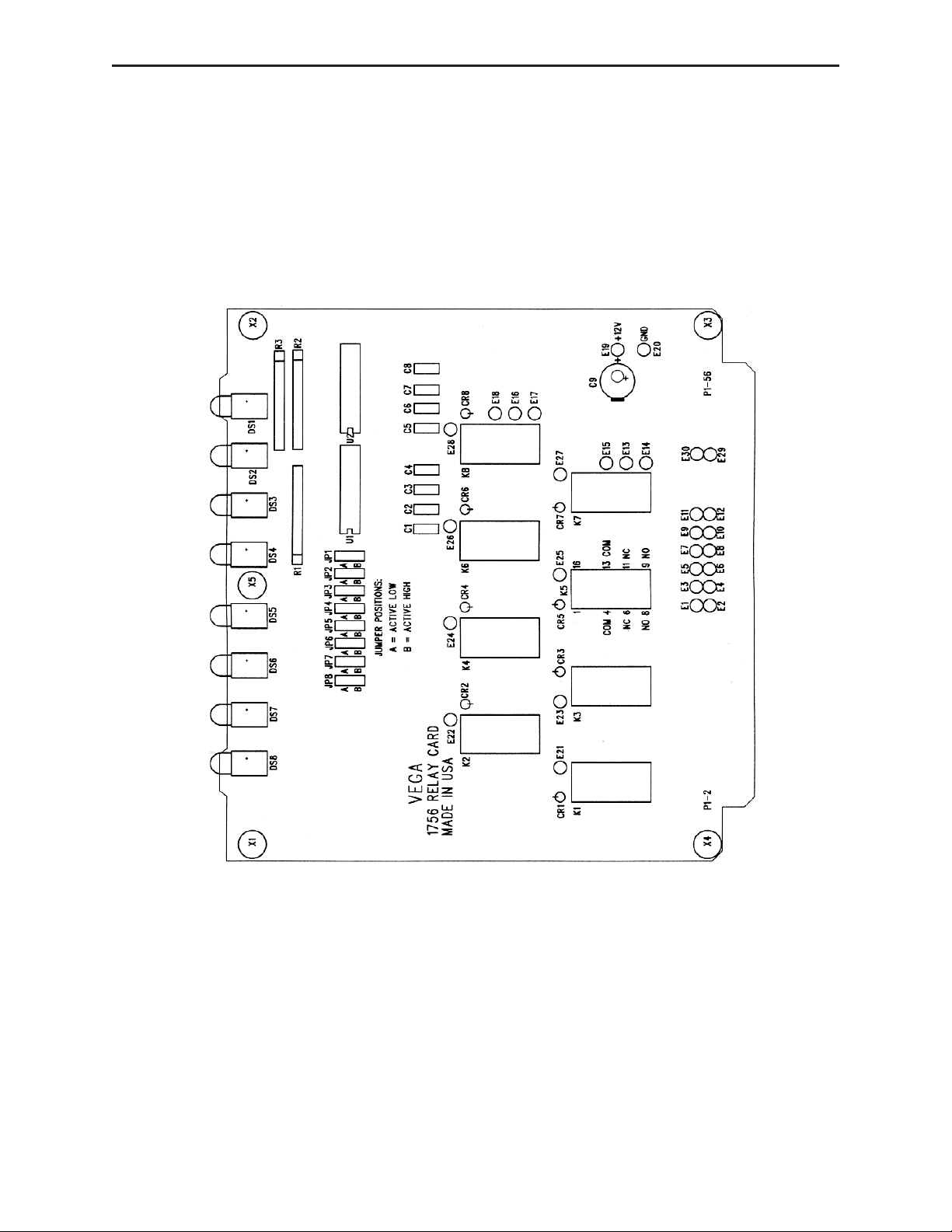
1756 Relay Components
Page 5

1756 Relay Board 5
1995
10:28:18
22
Mar
-Wed
1756.sch-1
Page 6

6 Vega
4. Connections
Warning - High Voltage! Remove Power Before Servicing!
High voltage may be present on this card (if used for switching phone lines with
superimposed DC current signaling) which could cause serious injury or loss of life.
Only qualified personnel familiar with this type of circuitry should work on this
equipment. To prevent injury, damaging the card or other equipment, remove power
before making connections.
4.1 Power connections
Connect positive 12 V
ground) to pins 39 and 40. For best performance, use at least 20 AWG or larger wire
for power connections.
4.2 Signal connections and card edge connector pin assignment
Refer to the schematic and the Table 1 on the next page (shows the 1756’s pin
assignments and has a blank for any customized functions that might be configured) for
the appropriate pin number to make connections. Use at least 24 AWG wire for signal
connections.
4.3 Special considerations for optional wiring
4.3.1 E Point Jumpers
The 1756 may be customized (using E point jumpers) to perform specialized switching
functions which accommodate a wide variety of applications. When using the E point
jumpers, take care to document the jumpers installed, and to mark the card with a
unique code that identifies the function and the changes made. A sheet has been
provided on the next page for this purpose.
4.3.2 Universal Circuit Area
The 1756 Octal Relay card has a provision for adding circuits in a universal circuit area
located on the PCB. This area will accommodate up to a 20 pin IC, or a smaller IC and
additional components for creating the desired circuit. i.e. The area can accommodate a
555 timer circuit for use as a delay for activating or dropout of a relay.
to pins 55 and 56. Connect the 12 VdcReturn (normally
dc
4.4 Securing the Connections
After all power and line connections are made, the wires should be neatly bundled and
secured in place to prevent accidental breakage when in service. Use one or more of the
cable guides supplied with the card rack, or tie in place with appropriate wire ties.
4.5 Interface Connector Numbering
The Tellabs (or equivalent) card cage interface connector pins may have a different
numbering scheme than the 1756. Table 1 depicts the card edge pin numbers as shown
in the schematic, which is also the same as one type of connector, followed by two
alternate numbering schemes as used on other connectors. Diligently review the actual
connections being used, to Table 1, to ensure proper connections are made for optimum
performance.
Page 7

1756 Relay Board 7
Table 1. Card Edge Connector Pin Assignments
Card Alt #1 Alt #2 Function User Connection
Edge Conn. Conn.
Solder Side
1 A A Relay 1B-NC
3 B B Relay 1B-NO
5 C C Relay 1B-COM
7 D D Relay 2B-NC
9 E E Relay 2B-NO
11 F F Relay 2B-COM
13 H H Relay 3B-NC
15 J J Relay 3B-NO
17 K K Relay 3B-COM
19 L L Relay 4B-NC
21 M M Relay 4B-NO
23 N N Relay 4B-COM
25 P P Relay 5B-NC, E1/E2
27 R R Relay 5B-NO, E3/E4
29 S S Relay 5B-COM, E5/E6
31 T T Relay 6B-NC, E7/E8
33 U U Relay 6B-NO, E9/E10
35 V V Relay 6B-COM, E11/E12
37 W W Relay 7A-NC
39 X X Pos. 12 Vdc Return (Gnd)
41 Y Y Relay 7A-COM
43 Z Z Relay 8A-NO
45 A
47 B
49 C
51 D
53 E
55 F
Component Side
2 1 1 Relay 1A-NC
4 2 2 Relay 1A-NO
6 3 3 Relay 1A-COM
8 4 4 Relay 2A-NC
10 5 5 Relay 2A-NO
12 6 6 Relay 2A-COM
14 7 7 Relay 3A-NC
16 8 8 Relay 3A-NO
18 9 9 Relay 3A-COM
20 10 10 Relay 4A-NC
22 11 11 Relay 4A-NO
24 12 12 Relay 4A-COM
26 13 13 Relay 5A-NC
28 14 14 Relay 5A-NO
30 15 15 Relay 5A-COM
32 16 16 Relay 6A-NC
34 17 17 Relay 6A-NO
36 18 18 Relay 6A-COM
38 19 19 Relay 7A-NO
40 20 20 Pos. 12 Vdc Return (Gnd)
42 21 21 Relay 8A-NC
44 22 22 Relay 8A-COM
46 23 23 E30
48 24 24 Relay #2 Control Input
50 25 25 Relay #4 Control Input
52 26 26 Relay #6 Control Input
54 27 27 Relay #8 Control Input
56 28 28 Pos. 12 Vdc Input
AA E29
BB Relay #1 Control Input
CC Relay #3 Control Input
DD Relay #5 Control Input
EE Relay #7 Control Input
FF Pos. 12 Vdc Input
Page 8

8 Vega
5. Operation
5.1 Description
This module has eight relays with active control circuitry, which can be used to switch
audio phone lines, or for general purpose switching.
Six of the relays are wired to the edge connector for use without additional wiring. Two
of these relays can be modified to have connections from one pole routed to perform
user defined special functions by removing zero ohm jumpers. Two relays have only
one pole connected to the rear connector, and the other pole is routed to E point
jumpers, for user defined special functions.
Front panel indicators provide visual identification of activated relays.
5.2 Operating capabilities
5.2.1 Relay
Each relay has a configuration of a two pole, double throw switching. The contact
rating of the relay is from low level audio signal, to 2 Amps at 30 Vdc max. It can also
switch 0.6 Amps at 120 V
.
ac
5.2.2 Active Output
For special applications, the ULN2804 Octal Driver output can be jumpered for use as
an active open collector switched low output. The practical rating of this output for this
application should be safely limited to: V
5.3 Controls and indicators
5.3.1 Input control
Activation of the relay circuits can be performed by a switched low input via a
transistor open collector or through a hard switch to ground.
5.3.2 LED indicators
An LED indicator on the front panel is illuminated when the corresponding relay is
energized, and off when not energized. This features allows for the easy identification
of active relays while the card is inserted in the rack.
6. Theory of operation
6.1 General
Activation of the relays is accomplished by active circuits with a switched low input. A
switched high input (jumper selectable) is available if required for special applications.
=30 Vdc,IC=250 mA, V
CEO
SAT
=1.5V.
6.2 Control circuits
6.2.1 Static Conditions
With no input applied, a pull-up resistor maintains a positive input to the ULN2804
driver. The driver inverts this high input to a low signal which is applied to the input of
a second ULN2804 driver. The low input to the second driver is inverted, and the
output of the second driver remains high. With the jumper in the “A” position, the relay
is left de-energized.
Page 9

1756 Relay Board 9
6.2.2 Switched low input
When a switched low is applied to the input, the first ULN2804 driver inverts the low
signal to a high, which is then applied to the second ULN2804 driver which in turn
inverts the high input to a low output. With the jumper in the “A” position, the low
signal energizes the relay and illuminates the corresponding front panel LED.
6.2.3 Switched high input
In special applications, a switched high input may be required to energize the relay.
This implies that a switched low input will be used to maintain the relay in an
unenergized condition. For this application, the jumper is moved to the “B” position.
Operation is similar to the that described for the switched low input, except now the
switched high will energize the relay and illuminate the LED.
6.3 Relay circuits
6.3.1 Relays 1-4
Of the eight relays, the first four (K1, K2, K3, K4) have both poles normally-opened
and normally-closed switch contacts routed directly to the 56 pin card edge connector.
The traces on the board simulate twisted pairs and therefore are conducive to 600-ohm
audio line applications, however they may be used for other switching applications.
6.3.2 Relays 5,6
Relays K5 and K6 are wired as the previous four however the second pole of the relay
is routed through E-point jumpers. The jumpers are installed as 0 ohm resistors and
have the same configuration as the previous four so that they can be used for switching
audio lines. One pole is wired direct and the other is wired through the resistors. These
resistors can be removed and the user can configure the relay to perform a function as
desired (as a relay tree or some other configuration).
6.3.3 Relays 7,8
Relays K7 and K8 have one pole wired directly to the card edge connector and the
second pole wired to E-point jumpers. These jumpers can be configured to perform any
function that the customer desires.
6.4 Spare Circuit Area
Included on this module is a spare circuit area that allows up to a 20-pin dual in-line
package integrated circuit or component carrier to be installed with allowance for
jumpering on the module to perform some logical function or additional feature the
customer would like installed. For example, a 555 timer could be installed to create a
timed relay function.
In addition, the 12V and ground termination’s are provided with e-point termination’s
to allow jumpers from power and ground to be used with the spare circuit area. Two
additional E-point jumpers are available, tied the card edge connector for additional
input/output functions.
Page 10

10 Vega
Suggestions or Comments
If you have suggestions or comments concerning this manual, please mail or fax
(402-467-3279) them to:
Vega Documentation
Telex Communications, Inc.
8601 East Cornhusker Highway
Lincoln, NE 68507
Warranty (Limited)
All Vega signaling products are guaranteed against malfunction due to defects in
materials and workmanship for three years, beginning at the date of original purchase. If
such a malfunction occurs, the product will be repaired or replaced (at our option)
without charge during the three-year period, if delivered to the Vega factory. Warranty
does not extend to damage due to improper repairs, finish or appearance items, or
malfunction due to abuse or operation under other than the specified conditions, nor
does it extend to incidental or consequential damages. Some states do not allow the
exclusion or limitation of incidental or consequential damages, so the above limitation
may not apply to you. This warranty gives the customer specific legal rights, and there
may be other rights which vary from state to state.
Page 11

1756 Relay Board 11
1756 Parts List
Page 12

1756 Octal Relay Specifications
Operating Temperature Range:
Power Requirements: 11 to 16 V
Relays: 8
Relay Contacts: 2 pole, double throw
Relay Contact Ratings: 2A@30V
Input signal: +12 V
0°Cto60°C
semiregulated
dc
200 mA idle,
600 mA max- all relays energized
dc
0.6 A @ 120 V
ac
Complies with FCC part 68, 1500Vdcsurge
nominal, 10 mA, each circuit
dc
8601 East Cornhusker Highway, Lincol, Nebraska, 68507
Phone: (402) 467-5321 / (800) 752-7560 Fax: (402) 467-3279
E-mail: don.poysa@telex.com, Web: www.vega-signaling.com
Printed in U.S.A.
©
November, 2000
 Loading...