

Page 1
VEGA Grieshaber KG
Am Hohenstein 113
Postfach 11 42
D-77757 Schiltach
Phone 0 78 36/50-0
Fax 0 78 36/50-201
11
+
12
-
+
1
-
2
ia-Trennbarriere
Typ 145
Ausgang
Zone 0
Eingang
ia safety barrier
type 145
TIB • Technical Information • Operating Instructions
Safety barrier
Page 2
Technical Information
2 Type 145
Application
The ia safety barrier type 145 is used in conjunction with a non-Ex-approved signal conditioning
instrument for intrinsically and galvanically isolated
supply at Ex-approved electrodes or Ex-approved
pressure sensors in hazardous areas and for signal
transmission.
Therefore Ex-approved transducers with oscillator
can be connected to standard signal conditioning
instruments (without Ex-approval) without breaking
the explosion regulations.
Attention:
Safety barrier and signal conditioning instrument
must not be installed in the hazardous area.
It should be observed that the supply voltage of the
signal conditioning instrument does not exceed
250 V.
Configuration
The electronics is located in a totally closed,
welded plastic housing. On the top and the bottom
of the front panel two clamp terminals for input and
output circuit are located. The output circuit (to
zone 0) is marked blue on the type plate.
An adapter is located on the rear for mounting on
carrier rail TS 32 (C-rail) acc. to EN 50 035 or
TS 35 x 7,5 (rail) acc. to EN 50 022 (snap-in
fastening).
Function
The non intrinsically safe circuit of a signal conditioning instrument is galvanically isolated and
converted into an intrinsically safe output circuit for
transducers (electrode or pressure sensor with
oscillator).
The safety barrier does not require any auxiliary
energy. The energy required for operation is taken
from the sensor circuit of the connected signal
conditioning instrument.
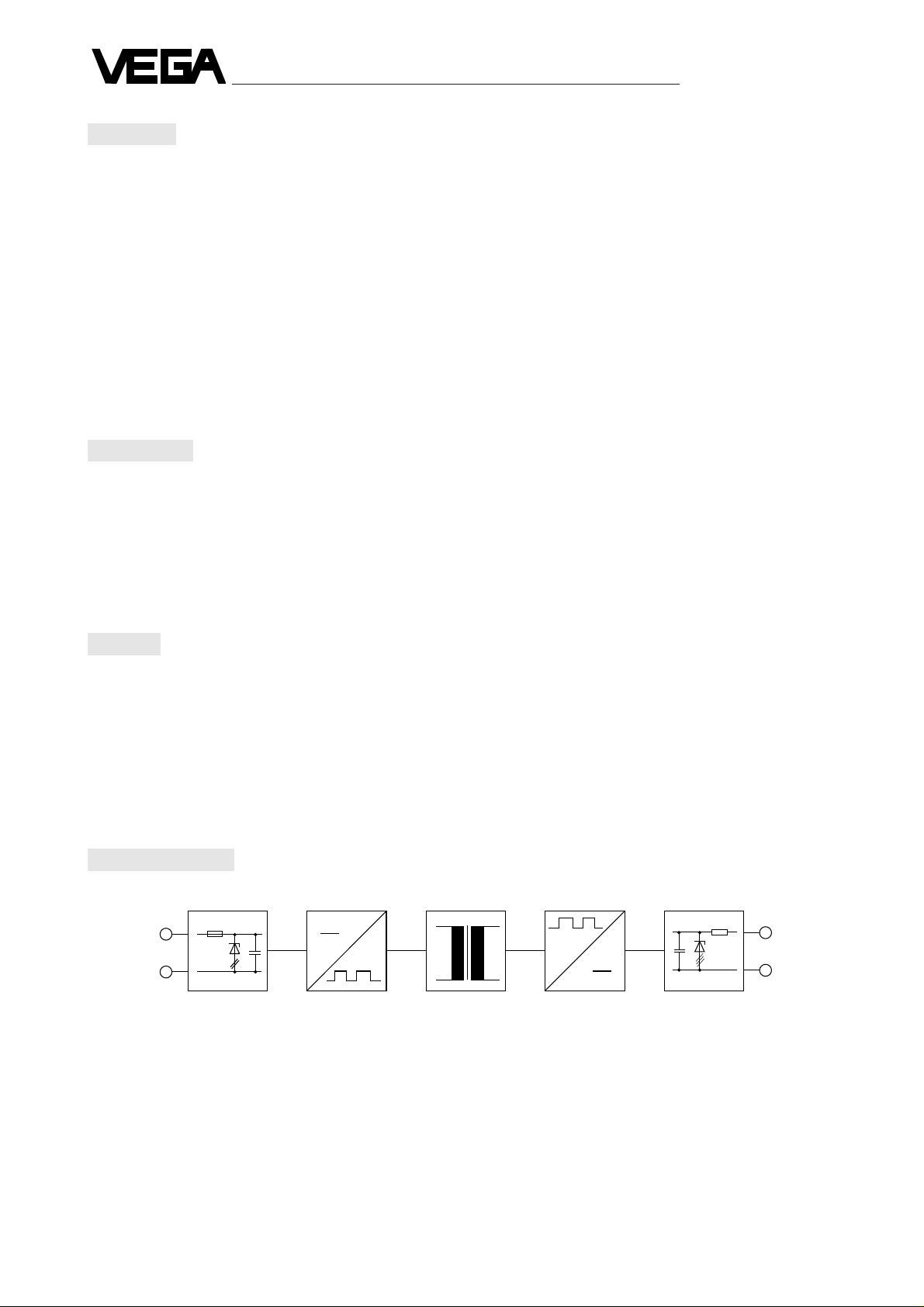
Functional principle
11
12
-
+
1
2
+
-
Ex-protective DC / AC Converter AC / DC Ex-protective
circuit control unit control unit circuit
input output
Page 3

Technical Information
Type 145 3
Technical data
Input Input voltage from the signal conditioning instrument
22 … 24 V DC
Input current 4 … 20 mA
Output Output voltage to the
transducer
(dependent on sensor current) 12 … 16 V
Output circuit
(intrinsically) 4 … 20 mA
Flame proofing intrinsic safety EEx ia IIC
Max. values U
max.
23,1 V
I
K
126 mA
P
max.
0,73 W
Max. permissible outer
inductance 0,5 mH
Max. permissible outer
capacitance 56 nF
Max. resistance per conductor
(to the sensor) 15 Ohm
General data Isolation
Input / output circuit galvanically
Testing voltage 4000 V eff.
Power consumption 300
µA; ± 60 µA
Terminals max. 2 x 1,5 mm
2
Material housing ABS, grey
Protection housing IP 40
terminal IP 20
Mounting on carrier rail
TS 32 acc. to EN 50 035
TS 35 x 7,5 acc. to EN 50 022
Permissible ambient temperature –20°C … +70°C / –4 … +158°F
Storage and transport temp. –20°C … +90°C / –4 … +194°F
Error limits
Linearity error < 0,2 %
Temperature influence < 0,08 % / 10 K
Page 4

Technical Information
4 Type 145
Dimensional drawing
Mounting instructions
13,5
41
86
72,5
16
25
77 (*73)
For mounting on TS 32 (C-profile) acc. to EN
50 035 and TS 35 x 7,5 (profile) acc. to EN 50 022
* Dimension only in conjunction with carrier rail
TS 35 x 7,5
Please observe when installing the ia safety barrier
type 145 that the parts of the measuring system
must be mounted acc. to the special conditioning
and regulations of the conformity certificates or test
certificates (the respective certificates are attached
to the consigment).
Furthermore the following is important:
- The safety barrier and the signal conditioning
instrument should be only used outside the Exarea.
- TS 32 or TS 35 x 7,5 carrier rail is required for
fastening (see sketch).
- An Ex-wiring in the switching cabinet is not
necessary when the safety barrier and the
respective signal conditioning instrument are
mounted adjacent to one another.
Page 5

Technical Information
Type 145 5
Electrical connection
+
-
11
12
1
2
+ -
+ -
1
2
1
2
Wiring diagram
Input
The non-intrinsically safe input of the safety barrier
(terminal 11 / 12) can be connected with standard
cable to the signal conditioning instrument.
Screened cable is recommended if electromagnetic
fields have to be expected.
Attention:
The screen should be single-ended.
Attention:
The connections of safety barrier (input / output)
should under no circumstances be exchanged.
Output
The wiring of the intrinsically safe output of the
safety barrier (terminal 1 / 2) with the transducer (in
hazardous area must be carried out according to
the local codes of practice and with reference to
the certificates of conformity supplied with the
barrier.
Set-up
• Carry out electrical connection acc. to the wiring
diagram.
• Carry out adjustment (with connected safety
barrier).
• For further details see the technical data sheet
of the connected sensor or signal conditioning
instrument.
hazardous area
hydrostatic
sensor with
oscillator
capacitive
electrode with
oscillator
intrinsically
safe circuit
VEGA
safety barrier
Type 145
non-Ex-approved
signal conditoning
instrument mains
supply ≤ 250 V
non-hazardous area
non-intrinsically safe
Page 6

VEGA Grieshaber KG
Am Hohenstein 113
Postfach 11 42
D-77757 Schiltach
Phone 0 78 36/50-0
Fax 0 78 36/50-201
2.11 992 / April '93Technical data subject to alterations
 Loading...