

Page 1
Technical Manual
1223C/1224 Series Tone-Remote Adapters
1223C Series Tone-Remote Adapter 1224 Expansion Module
098-0348
Rev. C
Page 2

Contents
General ........................................................1
Options ........................................................1
Operation ......................................................2
Installation .....................................................3
1224 Installation .................................................5
Tuning.........................................................5
1223C to1224 Tuning Instructions...................................5
Level Adjustments ...............................................5
Theory of Operation ..............................................6
Warranty (Limited)...............................................8
1223C Parts List .................................................9
Specifications ..................................................15
General
The Vega 1223C tone-remote adapter provides
a reliable means of remotely controlling a
two-way radio base station. It utilizes
industry-standard control tone frequencies and
timing to provide normal remote system
functions of transmitter keying and CTCSS
tone squelch monitoring.
Adding the optional Model 1224 expansion
module extends the capability to selecting one
of up to four frequencies or up to two paired
functions per module, for control of properly
equipped base stations. Both the 1223C and
1224 are designed to plug into telco shelves
(such as Tellabs Type 10 and Wescom or
Dantel 400 Type).
The adapter is mounted in or near the base
station it is to control, and is connected via hard
wire to applicable connection points. Interface
to the remote control console is through any
voice-grade medium, such as 600-ohm twisted
pair, leased telephone line, or microwave link.
Options
Model 1224 Expansion Module
This four-frequency decoder extends the
capability of the basic unit to accommodate up
to a four-frequency transmitter, or it can
provide two “on/off” ancillary base-station
functions of properly equipped base stations. A
second 1224 can be added to double the number
of frequencies or paired functions.
LPO-23 Lightning and Transient Protector
These gas-discharge tubes provide lightning
and transient protection to maintain system
integrity in a difficult environment. Vega
highly recommends the incorporation of this
option for each installation.
TO-23 Transformer Isolation
Isolation for transmit and receive interfaces is
provided by a TO-23 Transformer isolation
option. Transmitter line input isolation is
provided by a 600-ohm CT:600-ohm CT
transformer. Receiver output isolation is
provided by a 10-kilohm CT:10-kilohm CT
transformer.
1
Page 3

Compatibility
Vega Tone Remote Consoles
The following Vega consoles are fully
compatible with 1223Cs:
Model Number Description
C-510C/C-511/C-512 Two-frequency transmit
C-514B Four-frequency transmit
C-516 Six-line/two frequency
C-1614 Six-line/four frequency
C-582/C-583 Eight-frequency transmit
C-5110/C-5111/C-5112/C-5200 Ten-line/four frequency
Monitor. A “monitor” function disables the
base-station receiver CTCSS (Continuous Tone
Coded Squelch Signaling) sub-audible-tone-decoder
circuit, as required by FCC regulations, on stations so
equipped. The monitor function is accomplished by
decoding a 2050 Hz tone command, and providing a
jumper-selected switched transistor or relay-closure
output, to turn off the radio receiver CTCSS
decoder, allowing the console operator to
monitor the channel for other users before
keying the transmitter. A monitor LED is
provided on the front panel.
Other Vega consoles may be compatible with
1223Cs. Consult the factory for compatibility
information.
Other Manufacturers Tone-Remote
Consoles
Other consoles (such as Motorola, Ericsson and
GE) using industry-standard control tone
frequencies and timing are generally
compatible with these modules. If in doubt,
consult the factory for compatibility.
Operation
The 1223C decodes industry-standard tone
control sequences to provide the following
functions: PTT (push-to-talk/transmitter key);
CTCSS tone squelch receiver monitoring, and
with the optional 1224 expansion module,
selection of one of up to four frequencies for
transmission, or selection of up to two paired
functions, on base stations so equipped. A
second 1224 can be added to double the number
of frequencies or paired functions.
The unit is capable of two-wire or four-wire
operation, and is easily converted by means of
jumper plugs. In addition, full-duplex operation
can also be accommodated in the four-wire
mode, by a simple jumper plug.
PTT. Base-station keying is accomplished by
decoding the tone-control command, and
providing a jumper-selected switched transistor
or relay-closure output. Transmitter keying is
indicated by a front panel LED. During PTT
operation, the control tone portion (2175 Hz,
hold tone) of the voice-plus-tone signal
received from the remote console is removed
from the transmit audio applied to the base
station.
Three modes of monitor operation are
provided, any one of which is easily jumper
selectable.
1. Timed Mode. In this method of operation,
the monitor function operates for a timed period
(adjustable for up to 9 seconds) or until a PTT
command is decoded.
2. Latched Mode. Upon receipt of the monitor
command, the function is latched on, until reset
by a PTT command.
3. Timed/Refresh mode. A timed monitor
function is initiated by receipt of any tone
command. Any command received during the
timed period refreshes the timer for another full
cycle. This mode is extremely useful for
systems in which frequent dispatch/mobile
interchanges occur, or where frequent
frequency selections are made.
Alternate Function Capability. On single-user
stations not equipped for CTCSS operation, the
monitor function may be used for another
purpose, such as interrogation of a
status-reporting system at the station site.
Frequency Selection. Frequency selection is
provided by the optional Model 1224
expansion module(s). Each module can select
one of up to four frequencies. The number of
selectable frequencies varies with the number
of modules chosen. As shipped, one of the
frequency-select relays is always latched on,
and upon decoding a frequency-select
command, the latched relay is reset and the
relay associated with the command is latched
on (1-of N mode). Relay outputs can be
jumpered for latched or momentary outputs.
2
Page 4
Ancillary Functions. The 1224 expansion
module(s) can also be jumper selected to
provide up to two paired “on/off” toggle
functions per module, for control of properly
equipped base stations. Relay outputs can be
jumpered for latched or momentary outputs.
Installation
Connect an external 10- to 16-volt
semiregulated DC power supply to the card
shelf, with ground to J2-39 and positive to
J2-47.
Connect the two-wire leased line to J2-4 and
J2-6. For four-wire operation, move JP6 to B,
connect the outgoing line to J2-4 and J2-6, and
connect the incoming line to J2-8 and J2-10.
Also move JP4 to B if full-duplex operation is
desired.
Connect J2-38 to the transmitter mic audio
input, and J2-36 to the transmitter mic audio
return. If the TO-23 radio-interface isolation
transformer option is not installed, set JP12 and
JP13 both to the “A” position. If the TO-23
option is installed, set JP12 and JP13 both to the
“B” position.
If the mic input is a high-impedance type,
shielded cable is recommended. If the radio has
a high-level mic input, move JP7 to the “B”
position.
Connect the radio receiver audio output to J2-14
and J2-16. This must be an audio source after the
squelch circuit, to prevent sending continuous
noise to the remote console(s). If the radio
receiver audio output is single-ended and the
TO-23 option is not installed, be sure that the
“low” or “grounded” side of the radio receiver
audio output is connected to J2-16. If the TO-23
option is not installed, set jumpers JP10 and JP11
both to the “A” position; if the TO-23 option is
installed, set jumpers JP10 and JP11 both to the
“B” position.
3
Page 5

If a high-impedance point in the receiver is
used, shielded cable is recommended. If the
speaker output is used, move JP5 to B. Note that
when the speaker output is used, the radio
volume control will affect the audio output
level at J2-14.
Connect the radio PTT circuit to the PTT relay
contact terminals of the panel. Connect the
radio “monitor” circuit to the MON relay
contact terminals. Refer to the schematic.
1223C/1224 Block Diagram
4
Page 6

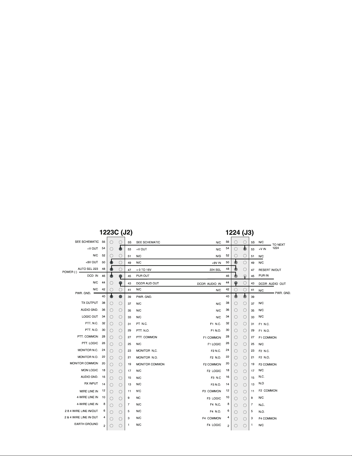
1224 Installation
Make the following essential connections
between the 1223C and 1224 boards: J2-53 to
J3-53, J2-50 to J3-50, J2-48 to J3-48, J2-46 to
J3-46, J2-45 to J3-45, J2-40 to J3-40, and J2-43
to J3-44 (not J3-43).
When one or more 1224 models are installed,
connect radio-frequency control circuits to the
function-control relay output terminals on the
PC board(s). Usually the common of each relay
contact switch is grounded and the normally
open contact connects to the radio
frequency-control terminals. Refer to the
schematic.
A few radios (such as some GE models) have
separate transmitter and receiver frequency
controls. Use the above connections for
transmitter frequency controls and connect the
receiver frequency controls to the second set of
relay contacts available at solder-pad terminals.
Refer to the schematic.
The 1223C line transformers are not designed
to operate on lines carrying direct current. If a
DC voltage is on the line, isolate with external
capacitors. If the line termination must conduct
direct current, install a 600:600-ohm
transformer designed for the current involved.
Tuning
All models have been factory-tuned to the
following frequencies:
Guard Tone/PTT Tone: 2175 Hz
MON Function Tone: 2050 Hz
Frequency-Select Function Tones
(where used)
F1: 1950 Hz F2: 1850 Hz F3: 1750 Hz F4: 1650 Hz
1223C to 1224 Tuning Instructions
1. Connect audio source to R52 lead on 1223c
through a 1uf dc blocking cap.
Relay/LED defeats and active-low
open-collector logic outputs have been
provided for special installations. Refer to the
schematics.
Transient protection has been provided near all
audio inputs and outputs. This is adequate for
transients up to at least 100 volts, but external
transient protection such as gas-discharge or
MOV devices should be installed to provide
some protection from very high-voltage
transients such as from lightning.
Although there is no complete protection from
lightning, gas-discharge devices such as North
Supply #S-561034 (two-wire) or S-561034
plus S-561035 (four-wire) provide a high
degree of protection when a nearby earth
ground is connected.
For additional protection , provisions have been
made on the 1223C for installation of either
Model LPO-23 gas-discharge-tube protectors.
An earth-ground terminal is also provided.
Vega will not replace units under warranty that
have obvious high-voltage damage such as
vaporized PC-board traces or melted
components.
2. Insert required decode signal at 0dbm for F1
of 1224 to be retuned.
3. Connect O’scope or rms. volt meter to TP3
and tune R39 for Max signal.
4. Repeat the same for F2 using TP4 and R53.
5. Repeat the same for F3 using TP1 and R6.
6. Repeat the same for F4 using TP2 and R1.
Level Adjustments
Level adjustments normally are required only
at the time of installation or due to base-station
changes.
Important: All test points have DC bias on
them. Use the “output” AC terminals and
scales on your meter, which places a DC
blocking capacitor in series with the meter.
1. Line Drive Adjustment
the receiver so that continuous noise is present.
Connect the meter to J2-4 and J2-6 (line should
also be connected) and adjust R94 (line output
level) for the desired line level (usually 0 dBm
or 0.8 V
rms
).
5
Page 7

2. Transmit Level Adjustment
Disable transmitter PTT circuit. Adjust R92
(line input level) to full clockwise. Have the
remote control console send a continuous PTT
command (no voice or loud room noise). The
panel should respond by energizing the PTT
relay and lighting the PTT LED. Adjust R92
(line input level) for a 1- to 1.1-V
reading at
rms
TP11. If the reading is lower, set R92 to
maximum. Key the remote control panel
several times to insure reliable operation of the
PTT relay.
Enable the transmitter PTT circuit and monitor its
deviation.
Have the remote control console send a PTT
command plus voice. The PTT relay and the
PTT LED should remain energized. With
voice (or a 1-kHz test tone) coming from the
remote control console, adjust R93
(modulation output level control) for proper
deviation.
In the receive condition, the receiver audio path
is from J2-14 through the line-output-level
control R94, U15C-10,8-, U11C-11,10-, R70,
U15A-2,1-, U11A-2,1-, U13, and T1 to the line
at TB1-5 and TB1-6. In the full-duplex mode
(JP4 to B), the path is from U15C-8 through
U11B-4,3 to U13.
2175-Hz Decoder Circuits
The PTT tone sequence generated by the
remote-control console is typically 2175 Hz at
+10 dBm for 130 ms (guard tone), followed by
a function-tone frequency at 0 dBm for 40 ms,
followed by 2175 Hz at –20 dBm (PTT holding
tone) for the duration of PTT operation.
The guard-tone and PTT-tone signal path is
from the line through T1 and JP6-A (two-wire)
or T2 and JP6-B (four-wire), input level control
R92, prefilter stage U5D-12,14-, first bandpass
filter U5C,A,B, and second bandpass filter
U4C,B,A to the 2175-Hz detector U1B.
3. Monitor Adjustments
Momentarily jumper TP2 to TP10 (GND). The
monitor relay and monitor LED should light for
a timed period. Adjust R46 (monitor time) for
the desired monitor period. Repeat as required. If
latched monitor operation (refer to page 3) is
desired, move JP1.
Have the remote control console send a monitor
command and check for proper operation.
Theory of Operation
Voice Circuits
In the “PTT ON” condition, the voice-signal
audio path is from the line through J2-4 and
J2-6, T1 and JP6-A (two-wire), or through J2-8
and J2-10, T2 and JP6-B (four-wire),
U14A-3,-1, U11D-8,-9, R70, U15A-2,-1, R93,
U15B-5, U10B-3,-4, C30, and R79 to the TX
audio output terminal J2-38. At the PTT tone
frequency (2175 Hz), audio from U11D-9 also
passes through the U14B,C,D bandpass filter
and is applied to U15A-2 180° out of phase, and
at equal amplitude to the signal path through
R70. This results in a deep notch at 2175 Hz and
effectively eliminates the PTT tone signal.
Logic Circuits
CMOS logic is used in these circuits. When the
term “low” is used, the DC voltage is near
ground potential. When the term “high” is used,
the voltage is near +9 V
.
dc
When the first 2175-Hz tone (guard tone) is
detected, TP1 goes low. TX gate activates with
the logic high at U6B-4 that energizes the PTT
Relay.
The PTT circuit, however, is not energized due
to the high at U6B-6.
The high-to-low transition at TP1 also triggers
the 240-ms timer at U2A-5, causing U2A-6 and
U10A-13 to go high. This enables the audio
path from JP6 through U14A-3, U4D-12,14,
and U10A-2,1 to the monitor decoder U3B,C,D
and all other function-tone decoders which may
be connected to P1-3.
6
Page 8

When a 1224 is installed, a frequency-select
function tone is always decoded during a PTT
command toneburst. A low from this
function-tone decode at P1-5 triggers a 50-ms
timer at U8A-5. Upon time-out of the 50-ms
timer, a 62-ms timer is triggered at U8B-12.
U8B-9 goes low and, if TP1 has again gone low
due to the presence of PTT tone, the PTT relay
K2 is energized from U6B-4 through
U9C-3,14. This disables the receive analog
gates, and enables the transmit analog gates
through a logic high at U6B-4 and U7B-1, 2, 8.
The U8B-9 and the TP1 lows also hold U8B-14
low through U6C and U12A. This U8B-14 low
disables time-out of the 62-ms timer by holding
capacitor C18 in a discharged condition.
When TP1 goes high from the absence of PTT
tone (the console operator has released the PTT
switch), the timing capacitor C18 charges to the
time-out voltage in 62 ms and the PTT relay is
deenergized. When the 62-ms timer times out, a
new PTT command toneburst is required to
energize the PTT relay; however, if a PTT tone
returns before timeout of the 62-ms timer, the
PTT relay remains energized. This minimizes
PTT losses from high-level noise transients or
from microwave-link flutter. The analog gates
are maintained in the transmit condition during
operation of the 62-ms timer by highs at U7B-1,
2, 8 from U6B-4.
If a 1224 is not installed, no frequency-select
decoders are included, and there is no decode
pulse to trigger the 50-ms timer U8A. The
auto-select 1223 J2-48 pin which is shorted to
ground by a 1224 four-frequency-select
decoder is high through R54 on models without
frequency-select decoders. This high enables
U10D, which causes U2A to time out in 150 ms
and allows U9B-15 to go high upon timeout of
the 150-ms timer. This low-to-high transition
triggers the 50-ms timer at U8A-5 through
U9G-7,10.
1223C Monitor-Function Decoder
When a monitor-function command is sent, the
guard-tone detection at TP1 triggers the 240-ms
timer U2A, which enables audio-signal passage
through analog gate U10A. U4D and U3A are
both high-gain stages and, therefore, the
function-tone signal at U3A-1 is a rail-to-rail
square wave. The square-wave function-tone
signal from U3A-1 is applied to the monitor
bandpass filter U3B,C,D through R32.
Monitor-bandpass-filter output is rectified by
CR3 and, after filtering, is applied to
comparator opamp U1A at U1A-3. U1A-1 goes
high, triggering the 50-ms timer at U8A-5
through U9F-6,11. Upon 50-ms timer timeout,
the 62-ms timer is triggered, but, since TP1 is
high due to the absence of PTT tone, the PTT
relay is not energized.
The low-to-high transition at U1A-1 triggers
the monitor timer U2B at U2B-12 through R31.
U2B-10 goes high and energizes the monitor
relay K1 through U9A-1,16 for a timed period.
If a PTT command is decoded before timeout of
the monitor timer, the high at U6B-4 resets the
monitor timer at U2B-13 through R47 and
U6D-12,11.
In the latched mode of operation, JP1 is in the B
position, and, when U2B is triggered, U2B-7
goes low, effectively short-circuiting the C16
charging path through R30, R28, and R46,
preventing C16 from charging to timeout
potential. Upon a PTT command, U6B-4 goes
high and resets the monitor latch at U2B-13
through R47 and U6D-12,11. U2B-10 goes low
and monitor relay K1 is deenergized.
In the refresh-monitor-timed mode of operation
with JP1 to A, JP2 to B, and JP3 to B, upon the
decode of any valid command, TP7 goes high,
triggering the monitor timer at U2B-12 through
JP3. A command will not reset the timer in this
mode, because the reset path is short-circuited
by JP2.
If a function command only was sent (no PTT
tone after the function tone), no low appears at
TP1 during the 62-ms timing period of U8B,
and the decode logic returns to the initial state
awaiting the next command sequence.
7
Page 9

1224 Four-Frequency Function-Tone
Decoder Module
Operation of the frequency-select
function-tone decoders is identical to that of the
monitor-function decoder, except that the
frequency-select decoders are tuned to a
different frequency.
Technical Assistance
Vega products are engineered to meet your
requirements of performance, reliability, and
compatibility. Technical assistance is offered
by correspondence or telephone, should it be
required, to assure your satisfaction.
The decoder output at U7A-1 is a high, and is
applied as a low to the F1-latch set input at
U9A-1 through U8A-1,18. Simultaneously, a
low is applied to the F1 latch reset input at
U9B-6, and, if JP2 and JP8 are in the A position
as shipped, to the reset input of all other
frequency-select function-tone decoders
through U8D-4,15, JP8A, JP2A, and J3-47.
When simultaneous set and reset inputs are
applied to the F1 latch, set dominates at the Q
output and the high at U9A-3 energizes the F1
relay through U8D-7,12. Simultaneously, the
reset low applied to F2, F3, F4, and all other
connected latches resets the previously set
latch.
On the trailing edge of the F1 detect pulse, the
reset pulse to the F1 latch and all other
connected latches terminates, but the low to the
set input of the F1 latch remains a few
microseconds longer due to the time constant of
R47 and C19. This ensures that latch F1 will
remain in the set condition.
Warranty (Limited)
All Vega signaling products are guaranteed
against malfunction due to defects in materials
and workmanship for three years, beginning at
the date of original purchase. If such a
malfunction occurs, the product will be
repaired or replaced (at our option) without
charge during the three-year period, if delivered
to the Vega factory. Warranty does not extend
to damage due to improper repairs, finish or
appearance items, or malfunction due to abuse
or operation under other than the specified
conditions, nor does it extend to incidental or
consequential damages. Some states do not
allow the exclusion or limitation of incidental
or consequential damages, so the above
limitation may not apply to you. This warranty
gives the customer specific legal rights, and
there may be other rights which vary from state
to state.
If the JP8 jumper plug is in a no-bridge
condition (hung on one side), F1 will reset F2
and vice versa, but other function-tone boards
are unaffected. This allows operation with more
than one 1-of-N group in
multiple-function-tone-board operation.
If JP2 is in a no-bridge condition, the same
thing happens with F3 and F4.
If JP8 is in the B position, a continuous reset
low is applied to both the F1 and F2 latches.
Upon termination of the F1 or F2 function-tone
decode pulse, the latch is therefore reset. This
momentarily energizes the relay for about 30
ms.
If JP2 is in the B position, the same thing
happens with F3 and F4.
8
Page 10

Page 11

Page 12

1223C Parts List
PART No. DESCRIPTION CKT SYM
010-0891 1223C TONE ADAPTER CARD
012-0065 PCB 1223C TONE ADPT
098-0348 MAN INST 1223/1224
012-0065 PCB 1223C TONE ADPT
021-6721 PANEL FRONT 1223C
031-0221 TEST SPEC 1223C/1224C
065-0447 PCB 1223
071-0558 SCHEMATIC 1223C
102-0060 CAP CER 6.8P S2L 5% 50V C 6
102-0290 CAP CER 100P S2L 5% 50V C19
104-0408 CAP TANT 1MF 35V C 1
C2
C3
C5
C17
C18
104-0748 CAP TANT 10MF 10V C 4
105-1011 CAP MYLAR .047MF 10% 100V C25
105-1116 CAP MYLAR .0047 1% C20
C21
110-1320 CAP CER .001MF 20% 50V C27
C28
110-1340 CAP CER .1MF SMALL C11
C22
C29
110-1345 CAP CER .0022MF 5% C 7
C8
C10
C13
C14
C15
C23
C31
112-1606 CAP ELEC 10MF 25V C26
C34
C37
112-1608 CAP ELEC 1.0MF 20% 25V C 9
C24
C36
112-1613 CAP ELEC 220MF 20% 16V C35
112-1671 CAP ELEC 22MF 16V 10%RD C16
112-1676 CAP ELEC 100UF 16V C12
C32
C33
130-0533 RES VAR 500K MT LIN R46
130-0639 RES VAR 10K PCB R11
R20
R24
R81
130-0673 RES VAR 10K 20T 3/8SQ R80
9
Page 13

1223C Parts List (continued)
PART No. DESCRIPTION CKT SYM
130-0725 RES VAR 10K LOG PC HADJ R92
R93
R94
131-1853 RES WW 68 5% 2W R86
132-0004 RES RN55C 32.4K 1% 1/4W R13
R17
R19
R23
R34
R37
R38
R41
R43
R64
R68
R70
R71
R72
R73
134-0212 RES RN55D 10.0K 1% 1/4W R 7
R12
R96
134-2837 RES RN55D 15.0K 1% 1/4W R 4
134-2852 RES RN55D 16.2K 1% 1/4W R42
134-2874 RES RN55D 182.K 1% 1/4W R82
134-2877 RES RN55D 20.0K 1% 1/4W R16
R18
R35
R36
R40
R44
R67
R74
134-2886 RES RN55D 332 1% 1/4W R33
134-2887 RES RN55D 27.4K 1% 1/4W R 2
R6
R91
134-2892 RES RN55D 60.4K 1% 1/4W R32
R56
134-2946 RES RN55D 953. 1% 1/4W R66
134-2947 RES RN55D 249K 1% 1/4W R25
134-2954 RES RN55D 9.53K 1% 1/4W R88
134-2991 RES RN55D 10.5K 1% 1/4W R10
134-3021 RES RN55D 475 1% 1/4W R27
134-3035 RES RN55D 8.66K 1% 1/4W R26
R90
134-3036 RES RN55D 274 1% 1/4W R39
134-3038 RES RN55D 976 1% 1/4W R45
134-3042 RES RN55D 31.6K 1% 1/4W R 8
134-3046 RES RN55D 28.7K 1% 1/4W R69
136-0003 RES COMP 8.2 5% 1/4W R77
136-0015 RES COMP 39 5% 1/4W R78
10
Page 14

1223C Parts List (continued)
PART No. DESCRIPTION CKT SYM
136-0020 RES COMP 100 5% 1/4W R62
136-0022 RES COMP 150 5% 1/4W R65
136-0027 RES COMP 390 5% 1/4W R79
136-0030 RES COMP 680 5% 1/4W R95
R97
136-0032 RES COMP 1K 5% 1/4W R 5
R21
R75
R83
R87
R89
136-0034 RES COMP 1.5K 5% 1/4W R50
136-0040 RES COMP 4.7K 5% 1/4W R53
R55
136-0044 RES COMP 10K 5% 1/4W R58
R59
R61
R63
136-0048 RES COMP 22K 5% 1/4W R15
R28
R30
R31
R47
R48
R51
R52
R54
R57
R60
136-0062 RES COMP 330K 5% 1/4W R22
136-0066 RES COMP 680K 5% 1/4W R14
136-0282 RES COMP 51K 5% 1/4W R49
161-0366 DIODE 1N4003 CR11
161-0573 DIODE LED T1 3/4 RED DIF DS1
DS2
180-0321 RELAY PCB 12V K1
K2
286-1766 CONN JUMPER PLUG JP1A
JP2A
JP3A
JP4A
JP5A
JP6A
JP7A
JP8A
JP9A
318-0246 XFORMER (10KCT-10KCT) T2
318-0259 XFORMER (600CT:600CT) T1
11
Page 15

1224 Parts List
PART No. DESCRIPTION CKT SYM
010-0802 1224 FUNCT DECODER CARD
012-0066 PCB ASSY 1224C
098-0348 MAN INST 1223/1224
012-0066 PCB ASSY 1224C
021-6701 PLN FRONT 1224C
031-0221 TEST SPEC 1223C/1224C
065-0448 PCB 1224C
071-0559 SCHEMATIC 1224C
104-0408 CAP TANT 1MF 35V C 7
C8
C9
C10
C17
C18
C22
C23
105-1099 CAP MYLAR .01MF 10% 100V C13
C14
C19
C24
110-1340 CAP CER .1MF SMALL C 6
C12
C26
C27
110-1345 CAP CER .0022MF 5% NPO C 1
C2
C3
C5
C15
C16
C20
C21
112-1606 CAP ELEC 10MF 25V C 4
C11
C25
C28
130-0673 RES VAR 10K 20T 3/8SQ R 1
R6
R39
R53
134-0195 RES RN55D 100K 1% 1/4W R23
425-0157 IC CMOS 4001 QUAD 2NOR U6
425-0181 IC OPAMP TL084 QUAD BFET U 3
U4
U5
U14
U15
425-0202 IC OPAMP 5532 DUAL RL600 U13
425-0204 IC CMOS 4025 TRIP 3NOR U 7
12
Page 16

1224 Parts List (continued)
PART No. DESCRIPTION CKT SYM
425-0215 INT CKT ULN2004A U 9
U12
425-0230 IC OPAMP LM358 DUAL U 1
425-0411 IC 4538 DUAL MONO U 2
U8
425-0452 INT CKT LM2931T ADJ REG U16
425-0461 IC HCMOS 74HC4066 QUADSW U10
U11
568-0005 BRACKET PC CARD INSERT
R25
R44
R60
134-0212 RES RN55D 10.0K 1% 1/4W R14
R15
R19
R20
R21
R27
R28
R29
R32
R42
R45
R46
R47
R58
R62
R63
R64
R65
134-0312 RES RN55D 150.K 1% 1/4W R 5
R10
R40
R54
134-2852 RES RN55D 16.2K 1% 1/4W R 4
R9
R35
R49
134-2887 RES RN55D 27.4K 1% 1/4W R24
R26
R33
R43
R57
R66
134-2916 RES RN55D 16.9K 1% 1/4W R 3
R8
R37
R51
134-2946 RES RN55D 953. 1% 1/4W R22
R56
13
Page 17

1224 Parts List (continued)
PART No. DESCRIPTION CKT SYM
134-2985 RES RN55D 64.9K 1% 1/4W R11
R12
R16
R17
R34
R36
R48
R50
134-2990 RES RN55D 6.65K 1% 1/4W R 2
R7
R38
R52
134-3037 RES RN55D 442 1% 1/4W R13
R18
R41
R55
136-0032 RES COMP 1K 5% 1/4W R30
R31
R59
R61
247-1523 LED HOLDER PCB MOUNT W/DS1-4
286-1766 CONN JUMPER PLUG
425-0181 IC OPAMP TL084 QUAD BFET U 1
U2
U6
U10
425-0230 IC OPAMP LM358 DUAL U 3
U7
425-0255 IC CMOS 4093 QUAD TRIG U 4
U9
425-0263 INT CKT ULN2804A U 5
U8
527-0272 SCREW FH 100PH 4-40X7/16
528-0258 SCREW PH 4-24X1/4 TYPE B
538-0075 NUT KEP 4-40
561-0623 SPACER SPCR LED .150 W/DS1-4
568-0005 BRACKET PC CARD INSERT
Options
LPO-23
146-0005 ARRESTER, GAS TUBE
TO-23
318-0246 ( 10KCT-10KCT) T3
318-0259 XFORMER (600CT:600CT) T4
14
Page 18

1223C/1224 Series Specifications
Operating Temperature Range: .................–20to+55°C for full specifications;
–30 to +70°C with reduced specifications
Power Requirements:..............................+10to+16Vdc,semiregulated
Model 1223C:............................55mAidle, 110 mA maximum at 12 Vdc
Model 1224: .............90mAidle, 85 mA maximum at 12 Vdc (1 of 4). Add 50 mA
maximum for refresh MON operation and 50 mA for each
additional relay “on” in non-1-of-N mode
Relay Contact Ratings: ...................................2A,30Vdcmaximum
Radio Interface: .......................................æ45 Vdc withstand rating
Line to TX Output Gain:.......–26to+16dBinto mic input load or –10 to +22 dB into
600-W load, adjustable
TX Output Level: ........–60to–18dBm(for mic-level output) or –40 to +2 dBm into
600-W load, adjustable
TX Output Impedance: ................22W TX ON, typical; 22 kW TX OFF, typical
RX Input Level: ...............................100mVrmsto16Vrms,adjustable
Audio Distortion: ..........................................2%THDmaximum
Frequency Response:.......æ1.5 dB, 300 to 3000 Hz, except at transmit notch frequency
Line Output Level: ..................................–30to+12dBm,adjustable
Line Input/Output Impedance: ..................................600W nominal
Sensitivity: ...............................Ultimate sensitivity, –60 dBm PTT tone
Noise Tolerance (5-kHz-bandwidth white noise): ......To18dBabove PTT tone level
at ultimate sensitivity
Tuning Range
Frequency-Select Function Tone Decoder:....1225 to 2025 Hz, continuously adjustable
Function-Tone Detection Bandwidth: ..........45Hzæ 12 Hz, frequency-select tones;
30 Hz æ6 Hz, MON function tone
MON Timer: .......................................1to10s,typical, adjustable
PTT Tone Detect Bandwidth: ...............50Hz,typical, with sensitivity set 12 dB
above threshold of detection
Tone-Detect Stability:....................æ0.3%, –20 to +55°C; æ0.4%, –30 to +70°C
Notch-Frequency Rejection: ....................................45dBminimum
Notch-Frequency Bandwidth: .................70Hzat–3dBpoints, typical; 1.0 Hz
at –40 dB points, typical
Non-Relay Outputs:..............Open collector, active low, 200 mA maximum, 50 V
(internal relay defeated) ............................................maximum
Dimensions (including PCB)
Model 1223C: ............5.58 in (14.2 cm) H, 5.43 in (13.8 cm) D, 1.40 in (3.6 cm) W
Model 1224:..............5.58 in (14.2 cm) H, 5.43 in (13.8 cm) D, 1.40 in (3.6 cm) W
15
Page 19

NOV. 2000 Printed in U.S.A.
8601 East Cornhusker Highway, Lincoln, Nebraska, 68507
Phone: (402) 467-5321 / (800) 752-7560 Fax: (402) 467-3279
E-mail: don.poysa@telex.com, Web: www.vega-signaling.com
 Loading...