

VeEX VePAL MX120e+, VePAL MX100e+ User Manual
MX100e+/MX120e+ e_Manual D07-00-050P RevD00
Page 1 of 115

Table of Contents
7.1.1 Header Settings
MX100e+/MX120e+ e_Manual D07-00-050P RevD00
Page 2 of 115
1.0 About this User Manual
2.0 Introduction to MX100e+ and MX120e+
2.1 MX100e+ Introduction
2.2 MX120e+ Introduction
3.0 Safety Information
4.0 Basic Operation
4.1 Keypad
4.2 Touch Screen Display
4.3 Battery
4.4 Connectors and Panels
4.4.1 Test Ports
4.4.2 Utility Ports
4.5 LEDs
4.6 Software Upgrade
5.0 Home Menus
5.1 Screen Layout
5.2 Screen Icons
5.3 Action Menu
6.0 Setup
6.1 Port Setup
6.2 Port Status
6.3 Laser Activation
6.4 Profiles
6.5 Measurement Settings
7.0 BERT
7.1 BERT Setup

7.1.2 Traffic Settings
MX100e+/MX120e+ e_Manual D07-00-050P RevD00
Page 3 of 115
7.1.3 Error Injection Settings
7.1.4 Control Settings
7.1.5 Starting/Stopping a BERT Test
7.2 BERT Results
7.2.1 Summary
7.2.2 Errors
7.2.3 Events
7.2.4 Alarms
7.2.5 Traffic
7.2.6 Rates
7.2.7 Delay
7.2.8 Saving BERT Results
8.0 RFC 2544 Conformance Testing
8.1 RFC 2544 Setup
8.1.1 Header Settings
8.1.2 Frame Settings
8.1.3 Threshold Settings
8.1.4 Throughput, Latency, Frame Loss, and Burst Settings
8.1.5 Control Settings
8.1.6 Starting/Stopping an RFC 2544 Test
8.2 RFC 2544 Results
8.2.1 Status and Events
8.2.2 Throughput
8.2.3 Latency
8.2.4 Frame Loss
8.2.5 Burstability
8.2.6 Saving RFC Results
9.0 Throughput Testing (Multiple Streams)

9.1 Setup
MX100e+/MX120e+ e_Manual D07-00-050P RevD00
Page 4 of 115
9.1.1 General Settings
9.1.2 Control Settings
9.1.3 Header Configurations (Individual Streams)
9.1.4 Traffic Settings (Individual Streams)
9.1.5 Error Injection Settings (Individual Streams)
9.1.6 Starting/Stopping a Throughput Test
9.2 Throughput Results
9.2.1 Viewing Test Results (Individual and Multiple Streams)
9.2.2 Global Results (Multiple Streams)
9.2.3 Individual Stream Results
9.2.4 Saving Throughput Results
10.0 OAM Testing
10.1 OAM Setup
10.1.1 Link Level 802.3ah OAM Setup
10.1.2 Service Level OAM
10.2 OAM Results
10.2.1 Link OAM Results
10.2.2 OAM Service Results
10.3 Definitions
10.3.1 802.3ah OAM Discovery
10.3.2 IEEE 802.1ag Definitions
10.3.3 Measurement Definitions
11.0 Monitor Mode - Pass Through (MX120e+ only)
11.1 Setup
11.2 Results
11.2.1 Errors
11.2.2 Alarms
11.2.3 Events and Status

11.2.4 Traffic Distribution Details
MX100e+/MX120e+ e_Manual D07-00-050P RevD00
Page 5 of 115
11.2.5 Delay and Rates
11.2.6 Port Selection
12.0 Loopback
13.0 V-SAM
13.1 V-SAM Overview
13.2 V-SAM Setup
13.2.1 General Settings
13.2.2 Services - Header
13.2.3 Services - Bandwidth
13.2.4 Services - Thresholds
13.2.5 Control Settings
13.3 Results
13.3.1 Configuration Results
13.3.2 Performance Results
14.0 Additional Tests
14.1 Packet Capture
14.2 Scan
14.3 NetWiz
14.4 Profile Scripting (MX100e+ only)
15.0 Common Functions
15.1 IP
15.2 Net Wiz
15.3 Settings
15.4 Files
15.5 Help
15.6 Backlight
15.7 Tools
16.0 ReVeal MTX Software

16.1 Profiles
MX100e+/MX120e+ e_Manual D07-00-050P RevD00
Page 6 of 115
16.2 Results
16.3 Software
16.4 Tools
16.4.1 Remote Control
17.0 Warranty and Software
18.0 Product Specifications
19.0 Certification and Declarations
20.0 About VeEX
Go back to ToC
1.0 About This User Manual
Every effort was made to ensure that the information contained in this user manual is accurate. Information is subject to change
without notice and we accept no responsibility for any errors or omissions. In case of discrepancy, the web version takes
precedence over any printed literature.
(c) Copyright 2006-2013 VeEX Inc. All rights reserved. VeEX, VePAL are registered trademarks of VeEX Inc and/or its affiliates in
the USA and certain other countries. All trademarks or registered trademarks are the property of their respective companies. No
part of this document may be reproduced or transmitted electronically or otherwise without written permission from VeEX Inc.
This device uses software either developed by VeEX Inc or licensed by VeEX Inc from third parties and is the confidential and
proprietary of VeEX Inc. The software is protected by copyright and contains trade secrets of VeEX Inc or VeEX's licensors. The
purchaser of this device agrees that it has received a license solely to use the software as embedded in the device, and the
purchaser is prohibited from copying, reverse engineering, decompiling, or disassembling the software.
This user manual is suitable for novice, intermediate, and experienced users and is intended to help you successfully use the
features and capabilities of the VePAL MX100e+/MX120e+ test set. It is assumed that you have basic computer experience and
skills, and are familiar with IP and telecommunication concepts, terminology, and safety.
For more technical resources, visit VeEX Inc web site at
If you need assistance or have questions related to the use of this product, call or e-mail our customer care department for
customer support. Before contacting our customer care department, you must have your product serial number and software
version ready. Please go to the
serial number on the back of the chassis. Please provide this number when contacting VeEX customer service.
Customer Care:
Basic Operations section for details on locating your unit serial number in the menus or locate the
www.veexinc.com.
Phone: + 1 510 651 0500
E-mail:
Website:
Go back to top Go back to ToC
customercare@veexinc.com
www.veexinc.com
2.0 Introduction to MX100e+ and MX120e+
VeEX™ MX100e+ and MX120e+ Metro Expert test sets are the next generation of Metro and Carrier Ethernet field test equipment
for Ethernet Networks. The units are lightweight, rugged and weather resistant, and feature Gigabit Ethernet and Fast Ethernet test
ports complete with advanced Triple Play verification capabilities. The test sets can be used in conjunction with the MPX100
loopback device offering simplified network testing and monitoring. The MX100e+ shares all the same features as the MX100+
unit, with the additional support of 100Mbps optical on SFP. Note that any reference in this manual to MX100e+ applies to the
MX100e+/MX120e+ e_Manual D07-00-050P RevD00
Page 7 of 115
MX100+ product and any reference to MX120e+ applies to MX120+ product, respectively.
Go back to top Go back to ToC
2.1 MX100e+ Introduction
The MX100e+ is part of the MX product family and is configured for:
Single Port Operation
Single Copper port 10/100/1000Base-T
Single Fiber port 100FX/1000Base-X
Test Applications (when the unit is operating in any of the physical ports above)
BERT: Unframed / Framed Layer 1, and Framed Layer 2/3 Ethernet traffic generation with user selectable test
pattern for Bit Error Rate analysis.
RFC 2544: Throughput, Back-to-Back, Frame Loss and Latency conformance tests in accordance with RFC 2544
specifications.
Throughput: Ethernet traffic generation and analysis with multiple streams to verify network throughput and jitter.
Loopback: Loop back the transmitted data while swapping the source and destination addresses of the MAC, IP and
UDP layers.
V-SAM test suite in conformance to ITU-T Y.1564 standard.
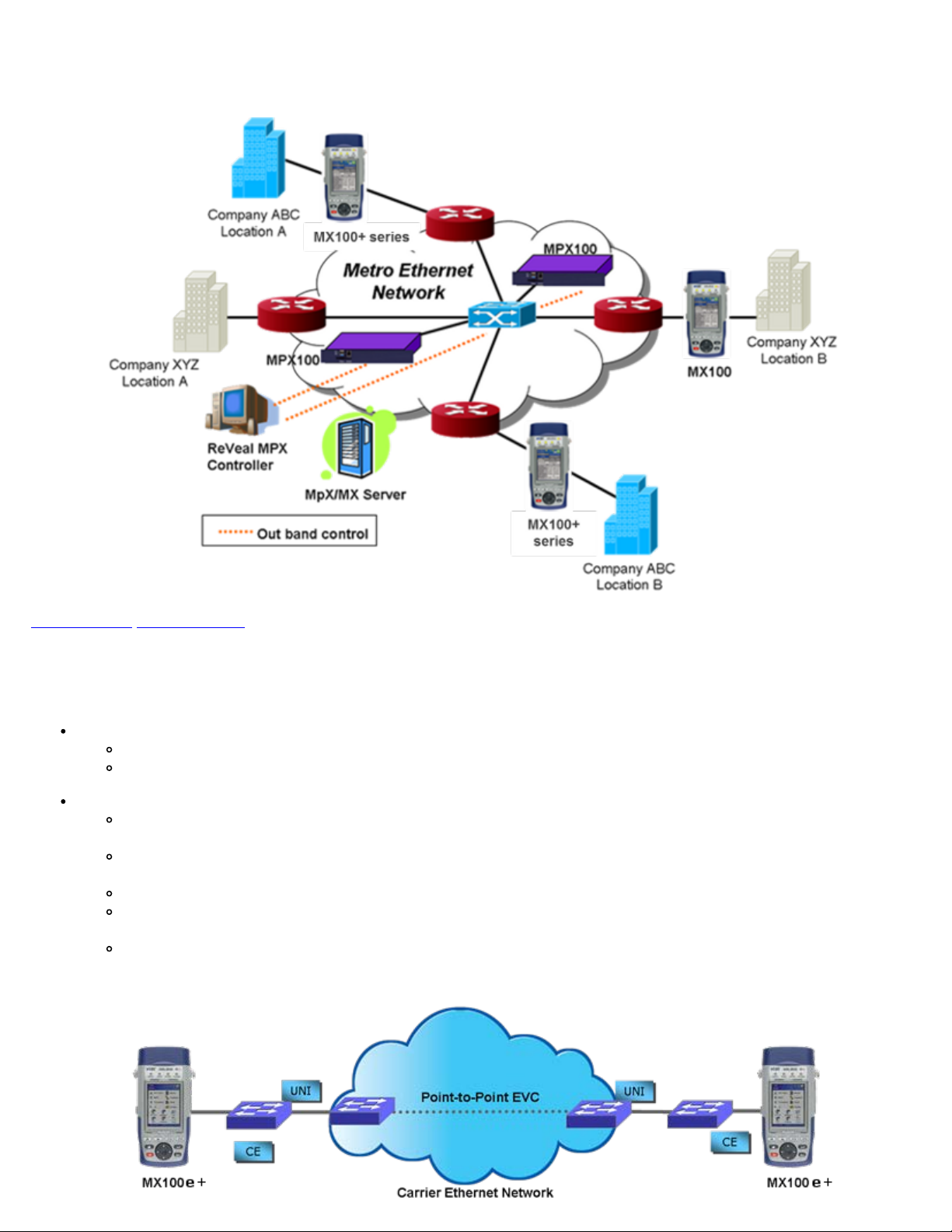
MX100e+ - End-to-End Performance Test Application
Go back to top Go back to ToC
MX100e+/MX120e+ e_Manual D07-00-050P RevD00
Page 8 of 115
2.2 MX120e+ Introduction
The MX120e+ is part of the MX product family - in essence the MX120e+ is similar to having two MX100e+ units in one chassis.
The default configuration of the MX120e+ allows for single port operation (same as the MX100e+), dual port operation, and pass
through monitor mode. Pass through monitor mode enables bidirectional monitoring between the two 100Base-FX/1000Base-X
ports or the two 10/100/1000Base-T ports.
Dual Port Operation
When the dual port interfaces and software options are enabled, the test set can operate a combination of two ports at the
same time with the following physical port operation combinations:
Port 1 10/100/1000Base-T and Port 2 10/100/1000Base-T (copper ports only)
Port 1 100Base-FX/1000Base-X and Port 2 100BaseFX/1000Base-X (fiber ports only)
Port 1 10/100/1000Base-T and Port 1 1000Base-X (copper and fiber port combination)
Port 1 and Port 2
Port 1 (any application) and Port 2 (Loopback)
Port 1 (Loopback) and Port 2 (Loopback)
Test Applications
When operating in single port operation, any of the following test applications are available. When operating in dual port
operation, one port can run any of these test applications while the other port provides loopback.
BERT: Unframed / Framed Layer 1, and Framed Layer 2/3 Ethernet traffic generation with user selectable test
pattern for Bit Error Rate analysis.
RFC 2544: Throughput, Back-to-Back, Frame Loss and Latency conformance tests in accordance with RFC 2544
specifications.
Throughput: Ethernet traffic generation and analysis with multiple-streams to verify network throughput and jitter.
Loopback: Loop back the transmitted data while swapping the source and destination addresses of the MAC, IP and
UDP layers.
V-SAM test suite in conformance to ITU-T Y.1564 standard.
Pass through monitor between two 10/100/1000Base-T copper ports or two 100Base-FX/1000Base-X fiber ports.
Go back to top Go back to ToC
3.0 Safety Information
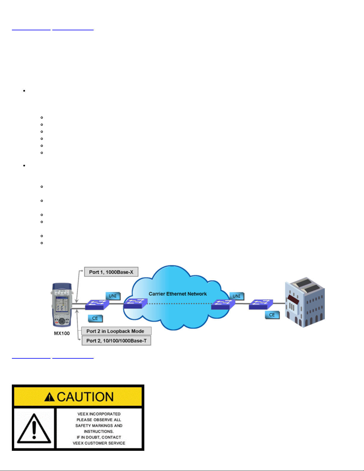
MX series - Dual Port Test Application
Safety precautions should be observed during all phases of operation of this instrument. The instrument has been designed to
ensure safe operation however please observe all safety markings and instructions. Do not operate the instrument in the presence
MX100e+/MX120e+ e_Manual D07-00-050P RevD00
Page 9 of 115
of flammable gases or fumes or any other combustible environment. VeEX Inc. assumes no liability for the customer's failure to
comply with safety precautions and requirements.
Go back to ToC
4.0 Basic Operations
Keypad
Touch Screen Display
Battery
Connectors and Panels
LEDs
Software Upgrade
Go back to top Go back to ToC
4.1 Keypad
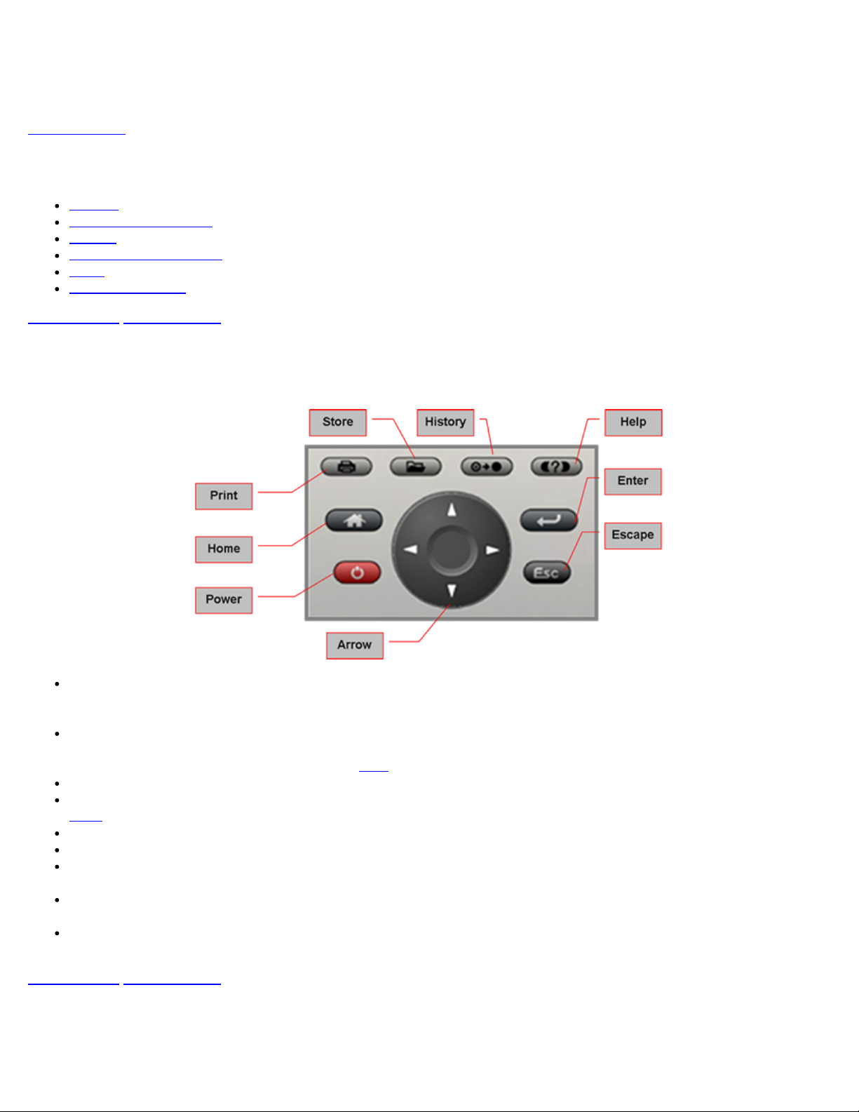
The keypad comprises the following keys:
Power key: The unit is powered on and off from the red key on the keypad. The button is recessed to prevent accidental
power on. Press the key for 3-5 seconds to turn the unit on. To turn off the unit, press the Power key for at least 2
seconds.
Save/Store key: Saves test results in the unit's memory. If the measurement is still running, it will provide a snapshot the
moment the key is pressed. The Save function provides automatic storage with automatic naming and time stamping
function. To process a stored file, please go to
Print key: For future use.
History key: The History key resets any blinking LED due to a history condition. For more details on the LED, please go to
LEDs.
Help key: The Help key brings the user to the online help, regardless of the current user interface location of the unit.
Home key: Brings the unit to its home menu regardless of its location on the user interface.
Arrow key: The Arrow key moves the cursor in any of the four supported directions (left, right, up, down). The Arrow key
works in conjunction with the Enter and Escape keys.
Enter key: The Enter key provides an enter sequence to the user interface. It is used in non touch screen operation mode
to enter menus and functions.
Escape key: The Escape key provides an escape sequence to the user interface. It is used in non touch screen operation
mode to escape menus and functions.
Go back to top Go back to ToC
If the unit does not respond, holding the Power key down by more than 10 seconds will force the unit to switch off.
Files.
4.2 Touch Screen Display
The LCD supports touch-screen operation. To operate the touch-screen, use the stylus located in the top cover to navigate the
menus and tabs. The unit can also be used in a non touch-screen mode (i.e., use the arrow, enter, and escape keys to navigate).
The location of the cursor on the screen is indicated by a focus state. The focus state varies depending on the function or section
of the test set. Please observe the following precautions:
MX100e+/MX120e+ e_Manual D07-00-050P RevD00
Page 10 of 115
Never use excessive pressure on the touch-screen as this may damage its functionality.
Never use sharp objects such as a pen, screwdriver, etc., as this may damage the surface.
Clean the surface of the touch screen using a soft cloth and mild detergent only. Do not use alcohol.
Go back to top Go back to ToC
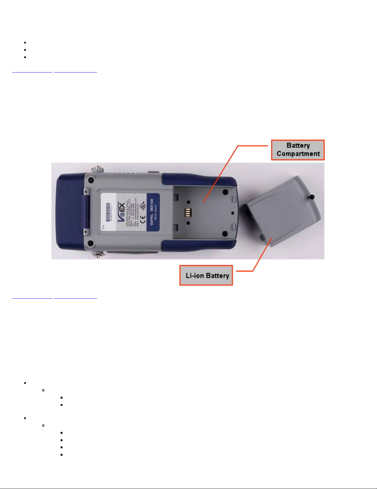
4.3 Battery
The VePAL100+ chassis is equipped with an intelligent Li-ion rechargeable battery pack which is located in the rear of the unit.
The battery will be partially charged upon delivery, so it is recommended to charge the battery fully before use. Please charge the
battery at room temperature to preserve its life and to obtain maximum charge. The battery is charged during operation provided
the unit is connected to the AC Mains using the supplied AC adaptor. Removing the battery while the unit is powered on is not
recommended - this may result in damage. Remove the rubber cover on the left side to connect the AC Main adaptor to the unit.
Go back to top Go back to ToC
4.4 Connectors and Panels
The connector panels are located at the top and the side of the unit.
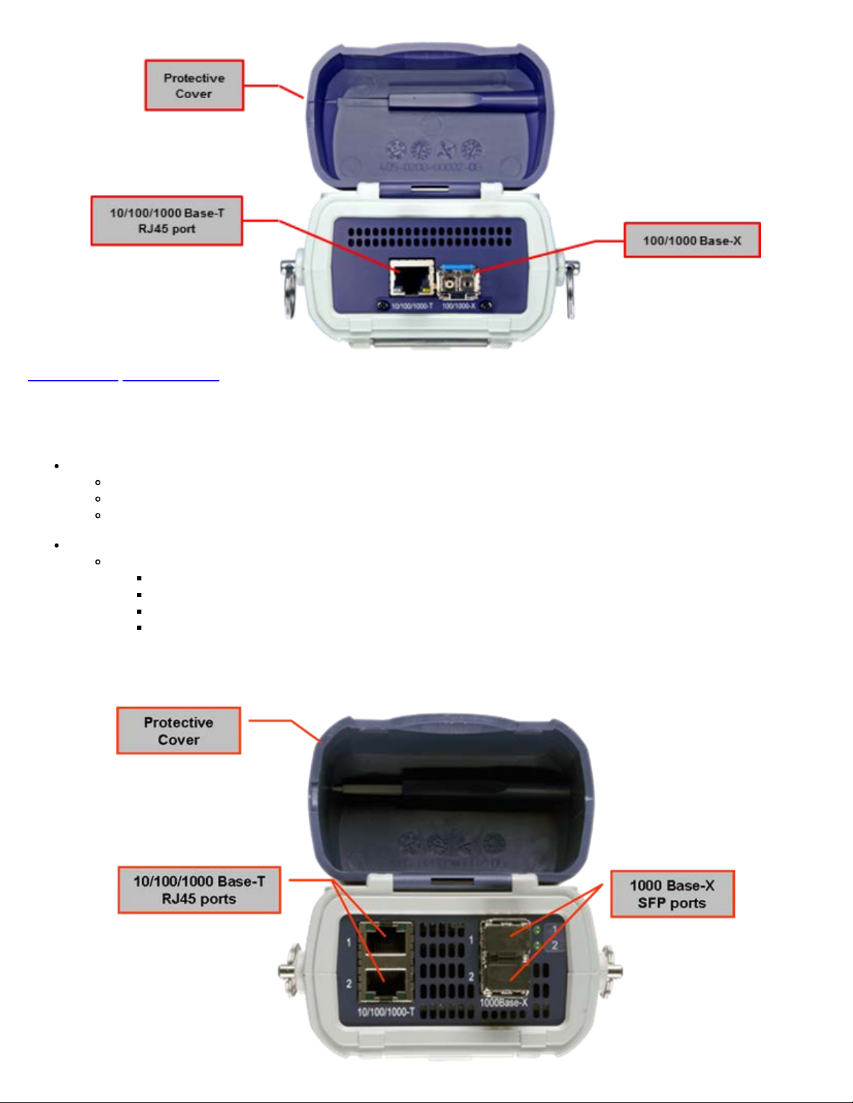
4.4.1 Test Ports
MX100e+ Test Interfaces
The MX100e+ is equipped with the following interfaces:
Electrical Ethernet Interface
Single 10/100/1000Base-T Port, RJ45 connector, IEEE 802.3 compliant
A green LED on the RJ45 connector flashes when there is activity on the network
The green LED is On when there is a valid Ethernet link with the network and off when there is no link
Optical Ethernet Interface
Single 1000Base-X SFP Port, LC connector
1000Base-SX (850nm)
1000Base-LX (1300nm)
1000Base-ZX (1550nm)
100FX (MX100e+)
MX100e+ Connector Panel
Go back to top Go back to ToC
MX100e+/MX120e+ e_Manual D07-00-050P RevD00
Page 11 of 115
MX120e+ Test Interfaces
The MX120e+ is equipped with the following interfaces:
Electrical Ethernet Interfaces
Dual 10/100/1000Base-T Ports, RJ45 connector, IEEE 802.3 compliant
A green LED on the RJ45 connector flashes when there is activity on the network
The green LED is On when there is a valid Ethernet link with the network and off when there is no link
Optical Ethernet Interface options
Dual 1000Base-X SFP Ports, LC connector
1000Base-SX (850nm)
1000Base-LX (1300nm)
1000Base-ZX (1550nm)
100Base-FX
Note: Port 2 can only be configured in loopback.
MX120e+ Connector Panel
Go back to top Go back to ToC
MX100e+/MX120e+ e_Manual D07-00-050P RevD00
Page 12 of 115
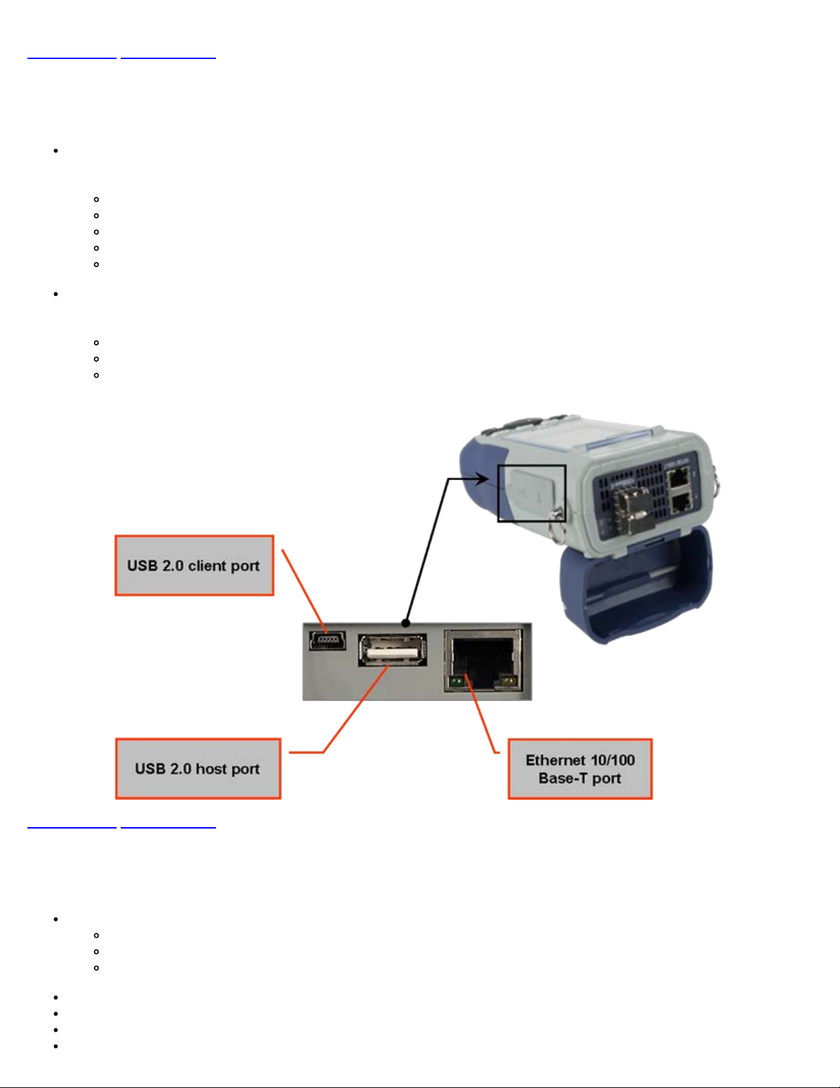
4.4.2 Utility Ports
The Ethernet and USB ports are located on the left and right side of the unit.
RJ45, 10/100Base-T port:
To access the Ethernet management port, remove the protective rubber cover on the right hand side of the unit to expose
the connector. Ethernet applications include:
IP connectivity testing
Transfer measurement results and test profiles between the instrument and a computer using ReVeal MTX software
Upload/download channel tables between the instrument and a computer using ReVeal MTX software
Upgrade the instrument software using ReVeal software
Remote control of the instrument using ReVeal software (optional)
USB Port:
To access the USB port, remove the protective rubber cover on the right hand side of the unit to expose the connector. The
USB port supports:
Memory drives
WiFi adaptor for WiFi testing application
VoIP Headset
Go back to top Go back to ToC
4.5 LEDs
The MX100e+ and MX120e+ test sets are equipped with the following LEDs:
Power LED: A single LED indicates the power state of the unit
The LED is off when the unit is powered off
The LED is green when the unit is powered on
The LED is orange when the unit is connected to the AC Main and powered off
Signal LED: Indicates presence of a valid input signal
Frame LED: Indicates presence of valid framing on the input signal
Pattern LED: Indicates test pattern synchronization in BERT, RFC, and Throughput modes
Alarm/Error LED: Indicates the presence of alarms or errors
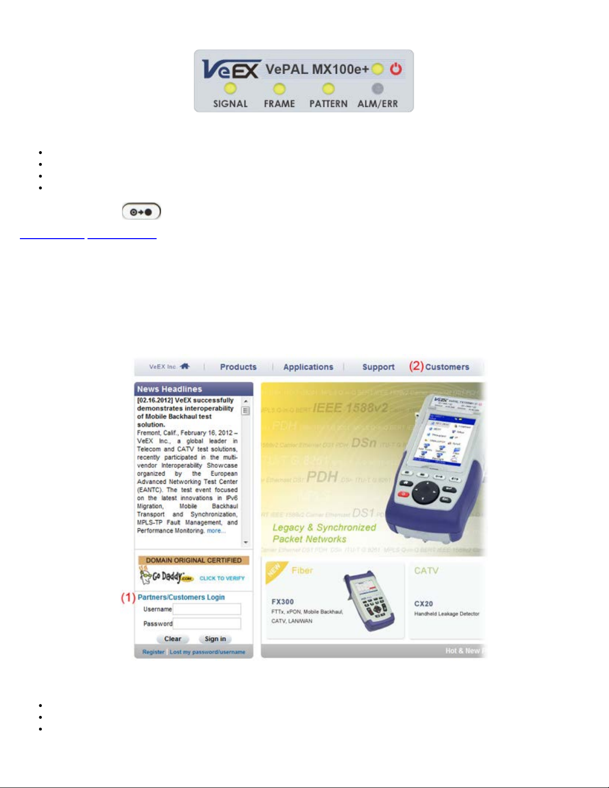
LED Panel
MX100e+/MX120e+ e_Manual D07-00-050P RevD00
Page 13 of 115
Note: Each LED is equipped with a History function
Green LED: Indicates that no alarm/error has occurred
Red LED: Indicates that at least one alarm/error has occurred during the test
Red flashing LED: Indicates any alarms/errors that have occurred
Grey LED: Indicates inactivity on the Signal, Frame, Pattern or Alarm/Error interfaces
Note: The History key
on the rubber keyboard resets the soft LEDs on the GUI.
Go back to top Go back to ToC
4.6 Software Upgrade
There are two methods of updating the test set software: manually or via ReVeal MTX software.
Manual Software Upgrade
To manually upgrade the test set software, download the latest version from the VeEX website.
Downloading Software from the VeEX website
Enter Username and Password under Customers Login (1).
Click on the Customers tab at the top of the screen after successfully logging in (2).
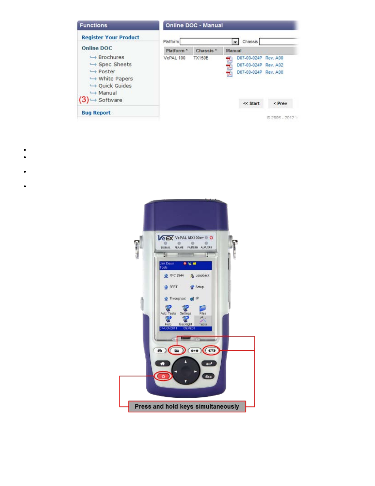
Click on Software, located in the Functions toolbar on the left side of the screen (3). Search for and download the latest
MX100e+/MX120e+ software onto the PC.
Installing New MX100e+/MX120e+ software
MX100e+/MX120e+ e_Manual D07-00-050P RevD00
Page 14 of 115
Unzip the file and copy the unzipped folder onto a USB stick formatted in the FAT-32 file format.
Verify that the MX100e+ unit is powered off and that the AC adaptor connected to the unit is charging the battery. Insert the
USB stick on the right side of the unit.
Press and hold the Save, Help and Power keys simultaneously. The unit should boot from the USB and load the new
software.
A message will appear on screen stating the upgrade is in progress. Installing the software will take around 10-15 minutes.
Note: Do not remove the USB memory stick until upgrade is complete. Doing so will interrupt the software upgrade and corrupt the
upgrade progress.
Updating with ReVeal MTX
Please refer to 7.4 Upgrade in the ReVeal MTX manual.
Go back to top Go back to ToC
MX100e+/MX120e+ e_Manual D07-00-050P RevD00
Page 15 of 115
5.0 Home Menus
The Home menu can be accessed at anytime during operation by pressing the Home key on the rubber keypad.
Screen Layout
Screen Icons
Action Menu
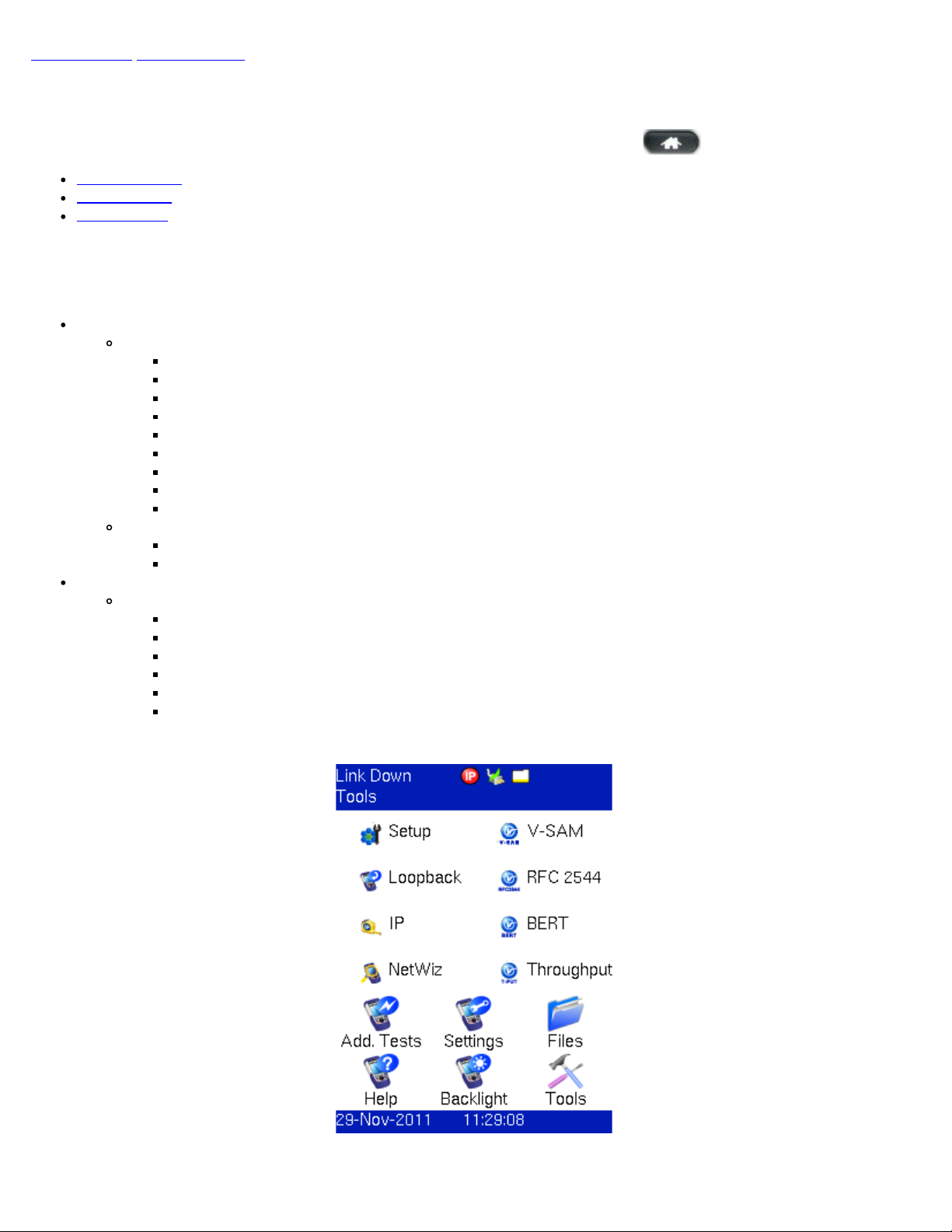
5.1 Screen Layout
The screen is divided into two presentation areas:
Top:
Test Applications specific to the MX100e+ and MX120e+ Port 1:
RFC 2544
BERT
Throughput (OAM)
IP functions related to the Ethernet WAN test ports
Loopback
Port Setup to configure test interfaces
Net Wiz
Monitor Mode (MX120e+ Port 1 only)
V-SAM
Test Applications specific to the MX120e+ Port 2:
Loopback
IP
Bottom:
Applications common to all VePAL100+ test sets:
Additional Tests
Settings
Files
Help
Backlight
Tools: IP connection status, Advanced IP features (Net Wiz, WiFi Wiz, VoIP, and IPTV applications)
MX100e+ Home Menu
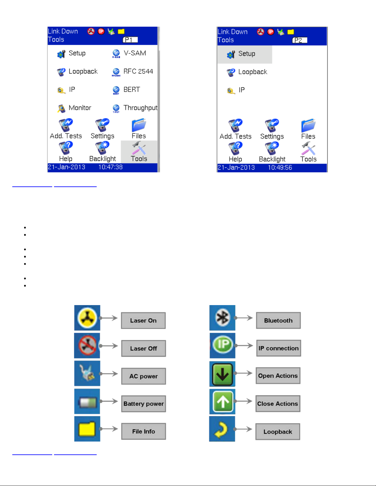
MX120e+ Home Menu for Port 1 (P1) MX120e+ Home Menu for Port 2 (P2)
MX100e+/MX120e+ e_Manual D07-00-050P RevD00
Page 16 of 115
Go back to top Go back to ToC
5.2 Screen Icons
The following icons are located at the top right hand corner of the screen:
Laser icon: Indicates if the optical transmitter in the SFP transceiver is switched On or Off.
Power icon: Indicates if the unit is being powered by the internal Li-ion battery or external AC power. If running on battery,
tap the icon for battery status.
File icon: Indicates File Storage. Tap icon to view memory capacity used.
Bluetooth icon: Future option (Bluetooth is not supported currently).
IP icon: Indicates status of IP connection on either test or management port. Green indicates a valid IP connection while
red indicates no IP connection.
Open / Close icon: Opens or closes drop-down menu and action bar.
Loopback icon: Indicates unit is in loopback mode.
Screen Icons
Go back to top Go back to ToC
5.3 Action Menu
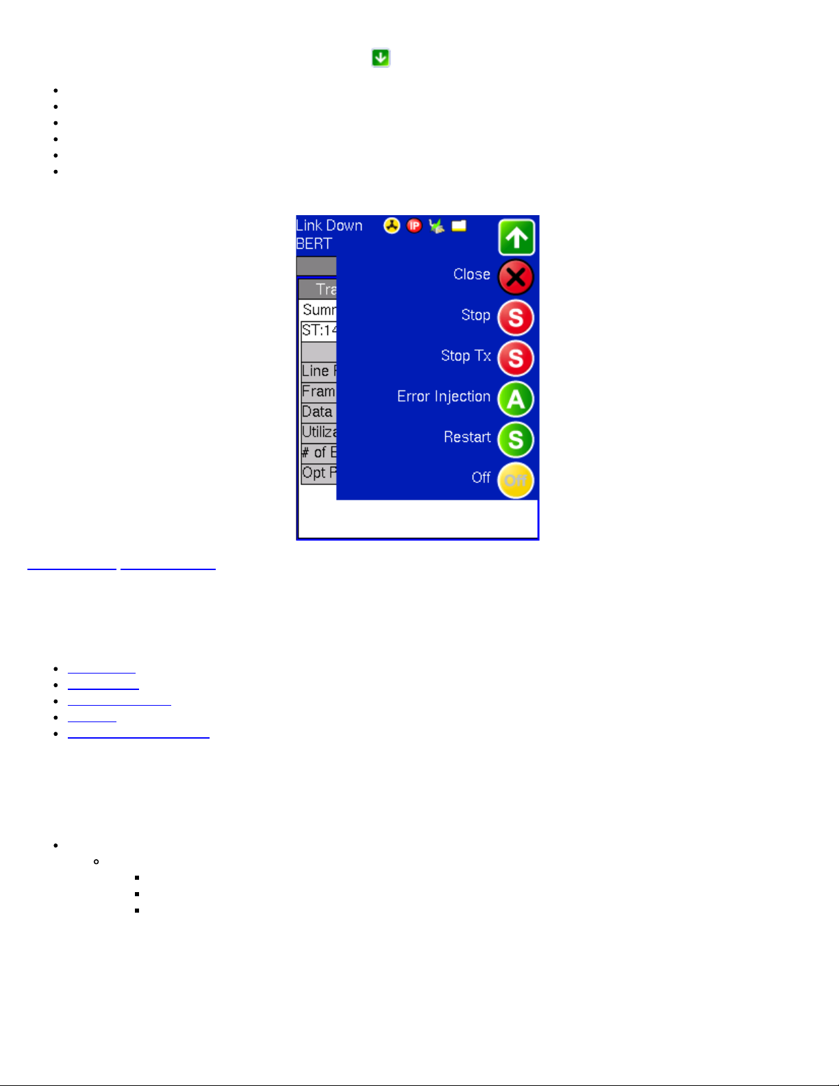
The Action Menu is accessed by tapping the Action icon in BERT or Throughput Testing. Menu options feature:
MX100e+/MX120e+ e_Manual D07-00-050P RevD00
Page 17 of 115
Close: Closes the Action menu
Stop: Stops the measurement
Stop TX: Stops the Transmitter
Error Injection: Injects an Error or Alarm depending on Error and Alarm generation settings
Restart: Restarts the measurement after it has been stopped by the user
Laser On/Off: Turns Laser On or Off depending on measurement application
Action Menu
Go back to top Go back to ToC
6.0 Setup
Test port(s) and network settings are required prior to performing any measurements or applications.
Port Setup
Port Status
Laser Activation
Profiles
Measurement Settings
6.1 Port setup
Port setup or the test interface configurations are accessed via the Setup menu located on the Home page. The user selects the
operation mode and the interface(s) that will be used to carry out tests.
Port Selections: Differs from MX100e+ to MX120e+
MX100e+ Interface selections:
Single Copper port 10/100/1000Base-T
100Base-FX/1000Base-X
Single Fiber port 1000Base-X
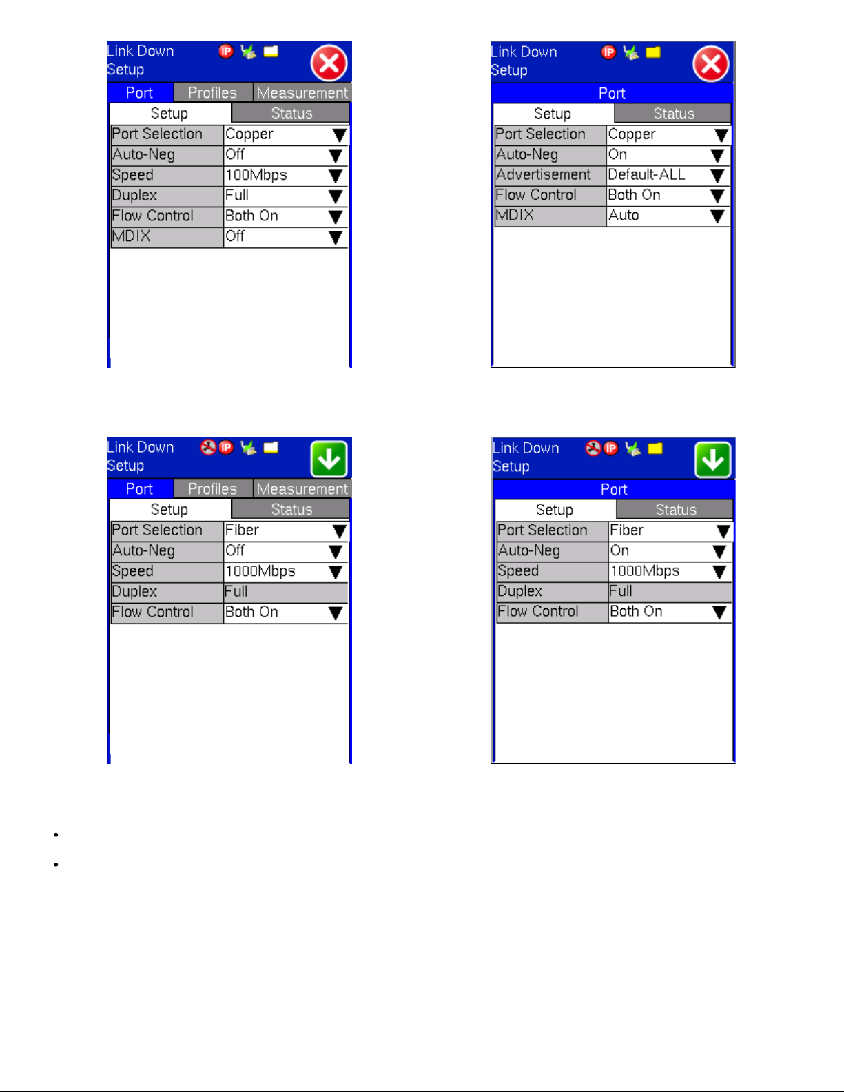
MX100e+ Port Settings - Copper MX100e+ Port Settings - Fiber
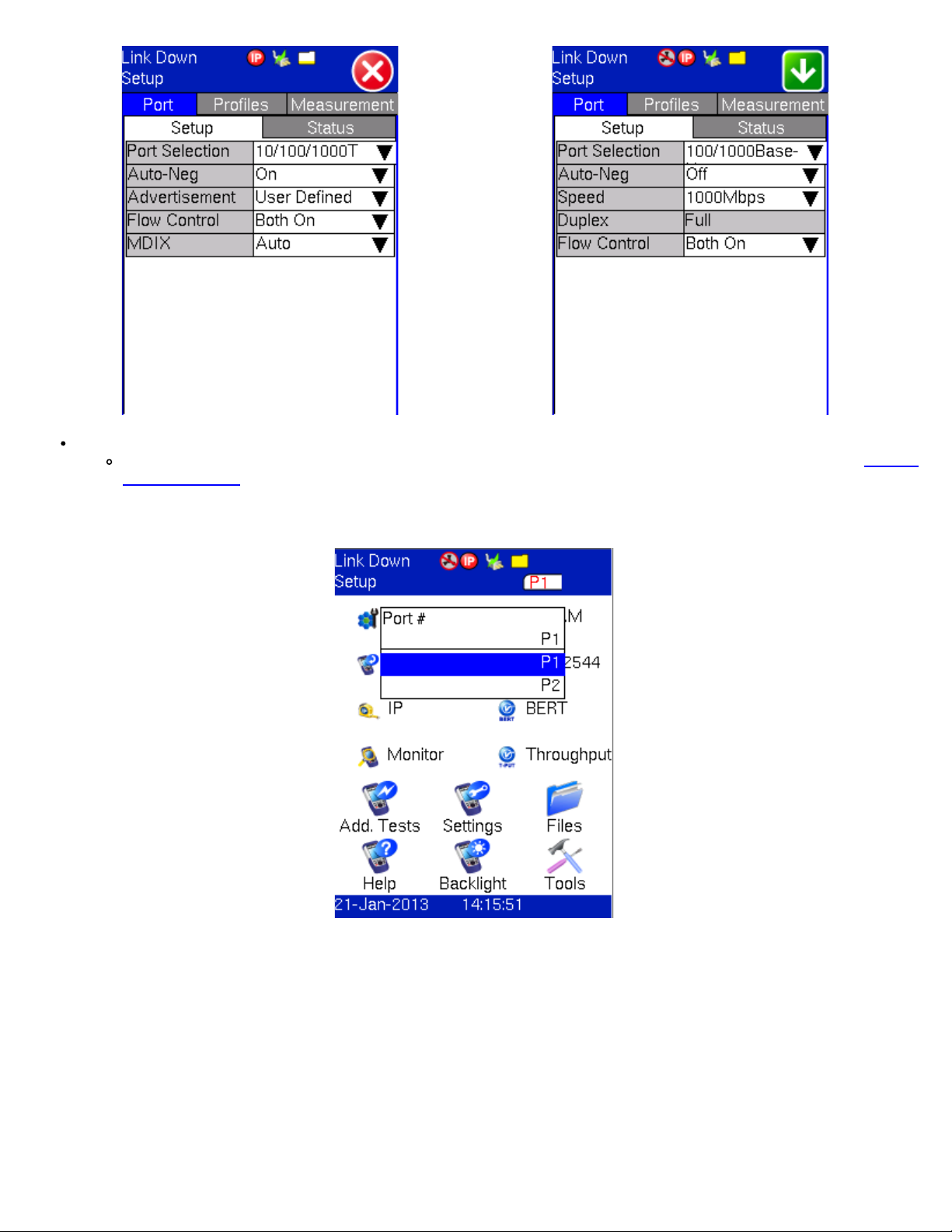
MX120e+ Interface selections:
MX100e+/MX120e+ e_Manual D07-00-050P RevD00
Page 18 of 115
Dual Port is the default selection. The user can switch between Port 1 and Port 2 by selecting P1 or P2. See Chapter
5.0 Home Menus for screenshots and more information on MX120e+ P1 and P2 home menus. Port 2 has limited
functionality.
MX120e+ Port Selection
MX120e+ Port Settings - Copper (P1) MX120e+ Port Settings - Copper (P2)
MX100e+/MX120e+ e_Manual D07-00-050P RevD00
Page 19 of 115
MX120e+ Port Settings - Fiber (P1) MX120e+ Port Settings - Fiber (P2)
Note: When Dual port mode is selected (MX120+ only), a P1 and P2 selection window appears at the top of the screen. Use this
window to select and configure the necessary port settings.
Auto Negotiation: On or Off. Matches the test set's negotiation settings to those of the link partner.
Advertisement: Default-All or User Defined.
Copper Port
Advertisement Selection
Copper Port
User Defined Selections
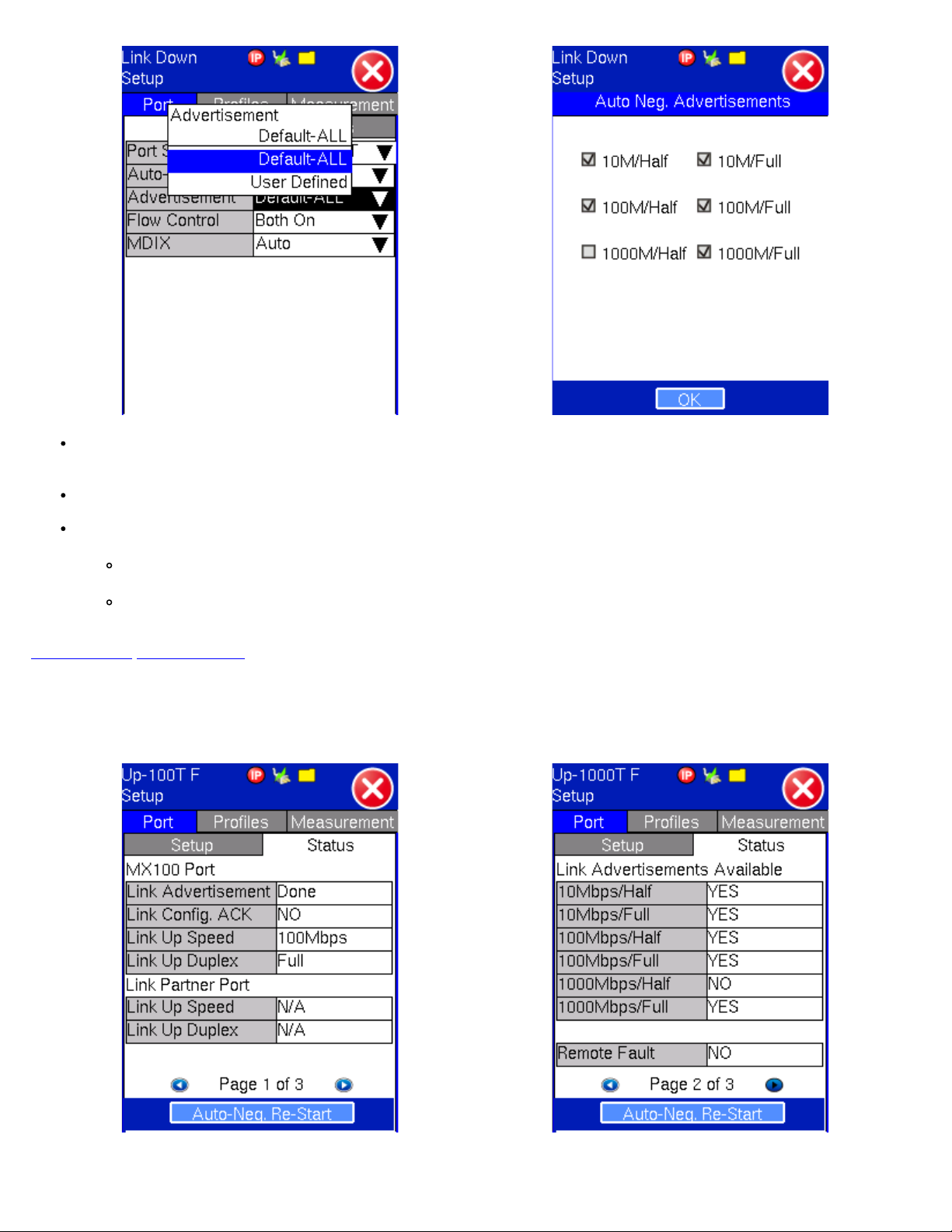
Speed: Only available when auto-negotiation is off. Select from 10Mbps, 100Mbps, or 1000Mbps when the 10/100/1000T
MX100e+/MX120e+ e_Manual D07-00-050P RevD00
Page 20 of 115
port is selected. 100 Mbps for 100Base-FX. 1000Mbps/1Gbps is fixed when the 1000Base-X port is selected.
Duplex: Only available when auto-negotiation is off for the 10/100/1000T port. Select from half or full duplex modes.
Flow control: On or Off. Once the operating mode and interfaces are selected, the user can independently configure the
auto-negotiation, speed, duplex, and flow control settings for each port (where applicable).
When flow control is enabled, the test set will respond to pause frames received by the link partner by adjusting the
transmit rate.
When flow control is disabled, the test set ignores all incoming pause frames from the link partner and continues
transmitting at the configured transmit rate.
Go back to top Go back to ToC
6.2 Port Status
MX100e+ Copper Port Status
Page #1
MX100e+ Copper Port Status
Page #2
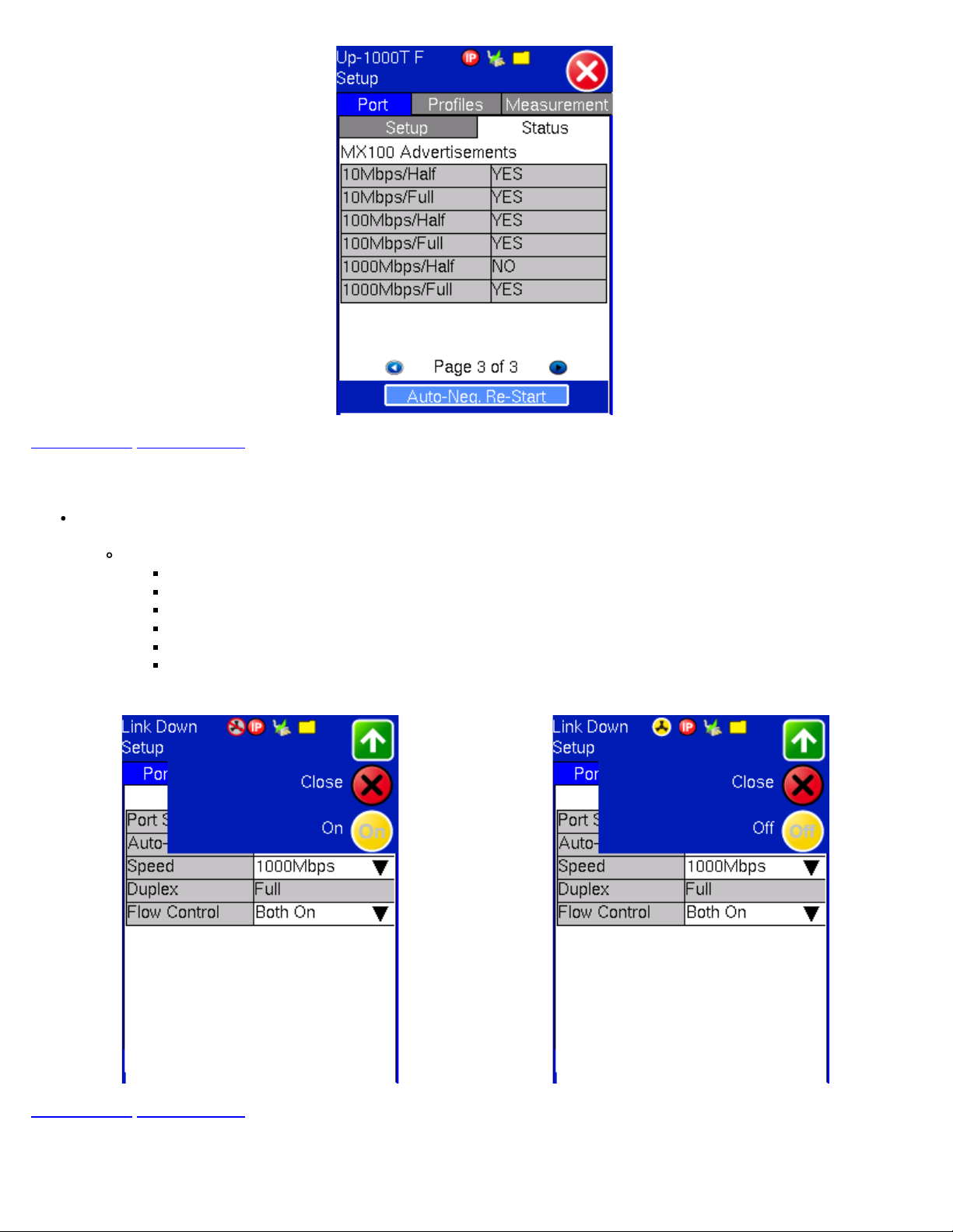
MX100e+ Copper Port Status
Page #3
Go back to top Go back to ToC
MX100e+/MX120e+ e_Manual D07-00-050P RevD00
Page 21 of 115
6.3 Laser Activation
LASER On/Off Operation: When the 1000Base-X port(s) is/are selected, the top drop-down menu appears in the
Setup/Port screen. From this drop-down menu the user is able turn the LASER On or Off.
The LASER may also be turned on/off from any of the following application menus:
BERT
RFC 2544
Throughput
V-SAM
Loopback
IP
Laser Operation - Off Laser Operation - On
Go back to top Go back to ToC
6.4 Profiles
Profiles Tab:
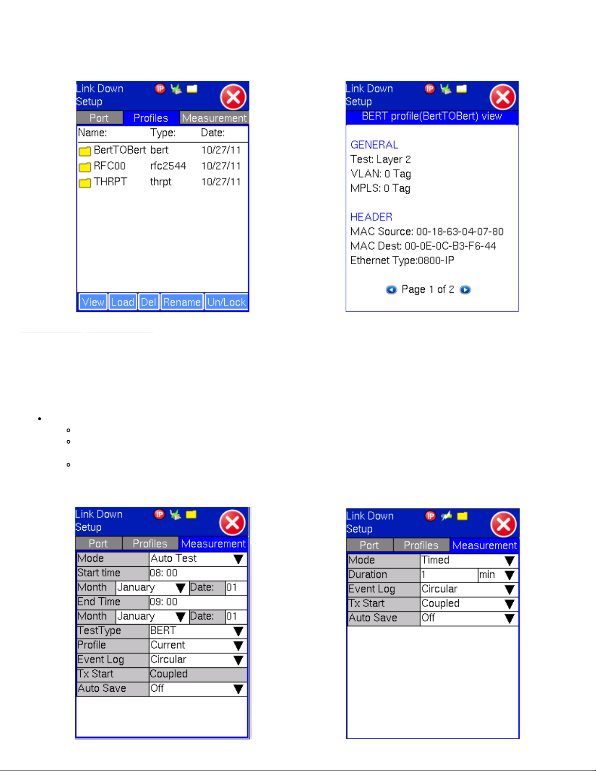
Previously stored profiles can be viewed, deleted and loaded from this screen. When the user loads a profile, the screen will
MX100e+/MX120e+ e_Manual D07-00-050P RevD00
Page 22 of 115
change automatically to the application that the profile corresponds to.
Profile Selection Profile View
Go back to top Go back to ToC
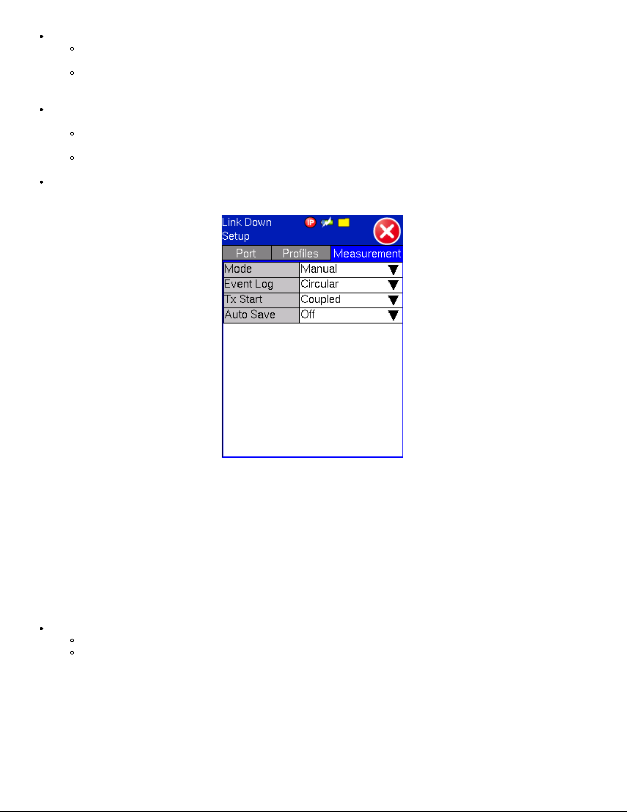
6.5 Measurement Settings
Measurement Tab:
The measurement and event log settings are configured in this screen.
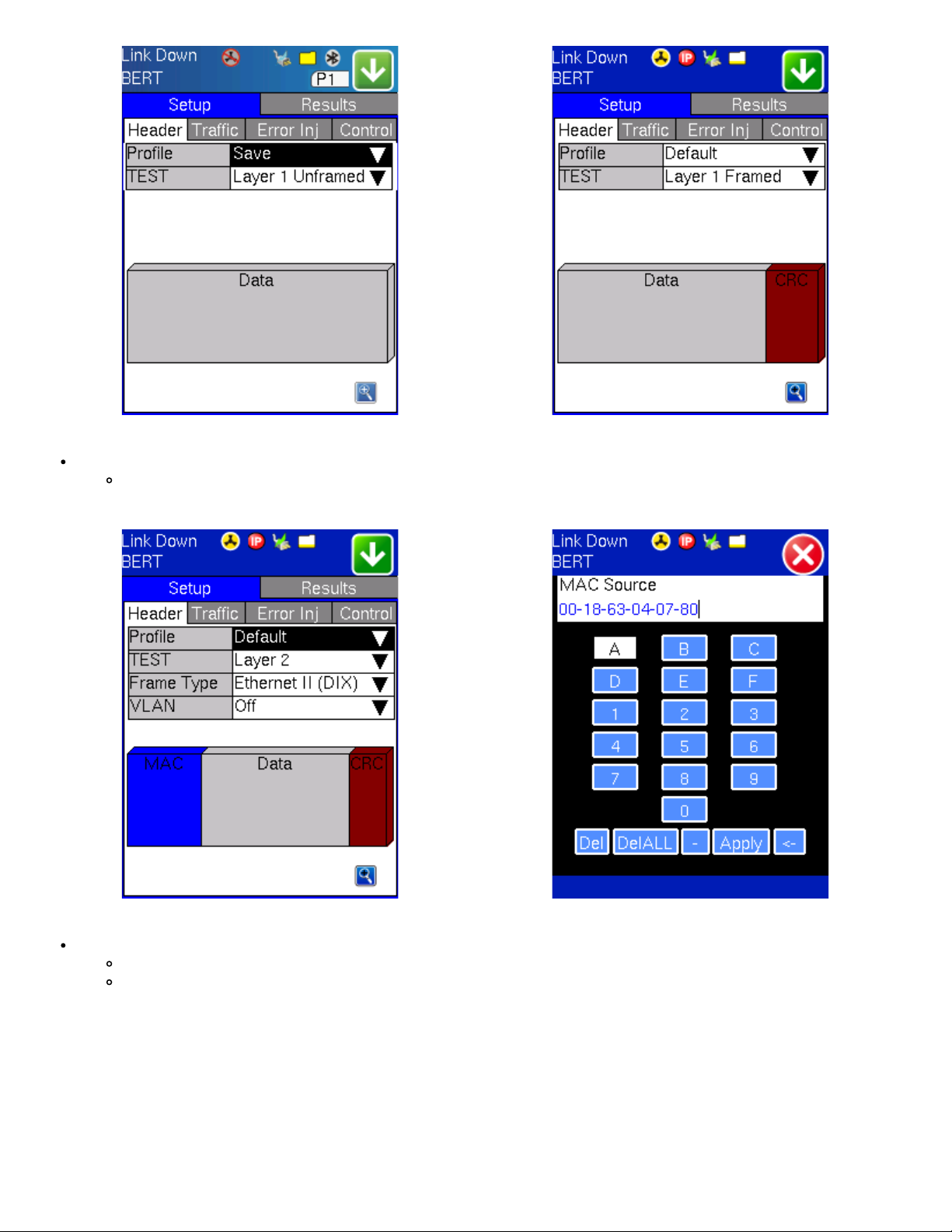
Mode: Manual, timed, or auto mode are available.
Manual mode: User starts and stops the measurements manually.
Timed mode: User defines the duration of the test. After the test is started, the test will run for the configured
duration and stop automatically.
Auto mode: User configures the start and end time of the test, selects the type of test to run, and a profile if one has
been previously stored. The test set must be powered on to carry out an automatic test.
Measurement Settings - Auto Test Measurement Settings - Timed
Event Log: Circular or Blocked. Up to 1000 event logs can be stored.
MX100e+/MX120e+ e_Manual D07-00-050P RevD00
Page 23 of 115
Circular: Only the latest events will be stored if there are over 1000 event logs. The oldest event will be deleted so
that the new event can be added.
Blocked event: Only the maximum number of events will be stored. Any event that occurs after the 1000th event will
not be stored. Event logs consist of a log of the start of test, end of test, errors, alarms, frame loss, etc. The log will
have a timestamp, event type, and count (number of errors occurring in that instant).
Tx Start: Tx & Rx (Coupled), or Tx Separate. Configure how the measurements are started when in BERT and Multiple
Streams test modes.
Tx & Rx (Coupled): Transmitter and receiver are turned on at the same time and the Tx and Rx measurements start
at the same time at the start of the test.
Tx Separate: Independent control (Start/Stop) of the transmitter is enabled. At the start of the test only the receiver
is turned on - the user must start the transmitter manually.
Auto Save: ON/OFF. When enabled, it saves the results automatically at the end of the measurements.
Measurement Settings - Manual
Go back to top Go back to ToC
7.0 BERT
7.1 BERT Setup
Overview:
BER testing at Layer 1, 2, 3, and 4 is supported. The test can be configured to use either regular PRBS patterns, stress patterns or
user defined test patterns to simulate various conditions. All patterns are encapsulated into an Ethernet frame to verify bit-per-bit
performance of the circuit under test. Prior to testing, the test layer, frame header, traffic profile, error injection, and control settings
of the far-end device (if applicable) must be configured.
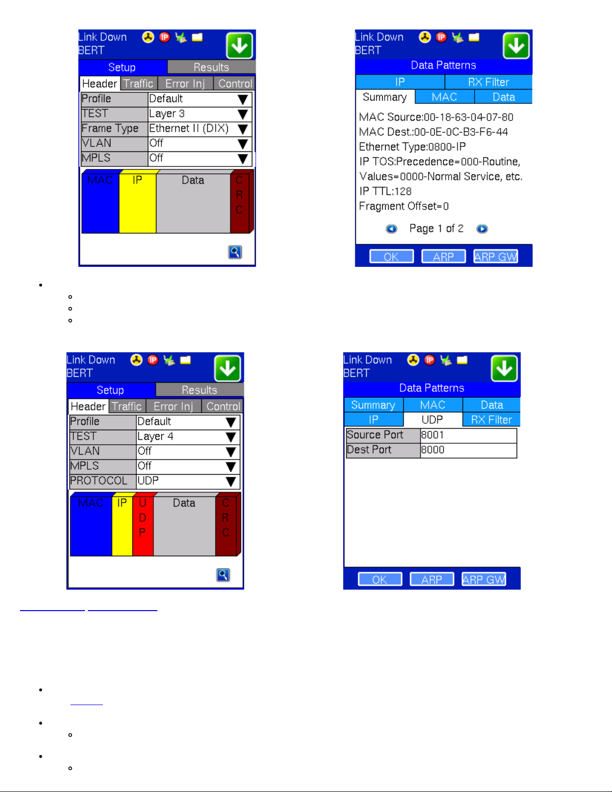
Layer 1: Unframed mode (fiber ports only) or Framed mode
Unframed mode: Test traffic consists of a bit stream of the selected test pattern
Framed mode: Test pattern is encapsulated into a valid Ethernet frame with SOF, Preamble and CRC field
BERT Setup - Header (Layer 1 Unframed) BERT Setup - Header (Layer 1 Framed)
Layer 2: Framed BERT (same as Layer 1 Framed)
MX100e+/MX120e+ e_Manual D07-00-050P RevD00
Page 24 of 115
MAC Address: A default or user configured Media Access Control (MAC) address is added to the frame
BERT Setup - Header (Layer 2) BERT Setup - MAC address editing
Layer 3: Framed BERT (same as Layer 1 & 2 Framed)
MAC Address: A default or user configured Media Access Control (MAC) address is added to the frame
IP Address : A default or user configured IP address is added to the frame
BERT Setup - Header (Layer 3) BERT Setup - Header Summary (Layer 3)
Layer 4: Framed BERT (same as Layer 1, 2 & 3 Framed)
802.3 Raw (IEEE 802.3 frame without LLC) - Not available when Layer 3 is selected
MX100e+/MX120e+ e_Manual D07-00-050P RevD00
Page 25 of 115
MAC Address: A default or user configured Media Access Control (MAC) address is added to the frame
IP Address: A default or user configured IP address is added to the frame
UDP/TCP: A user defined source and destination port address is added to the frame
BERT Setup - Header (Layer 4) BERT Setup - Header (Layer 4) UDP Settings
Go back to top Go back to ToC
7.1.1 Header Settings
The test layer, frame header, traffic profile, error injection, and control settings of the far end device (if applicable) must be
configured prior to testing.
BERT Profile: Load a previously configured test profile or create a new profile from existing settings
Profiles for more details on how to create new profiles
See
Test: Select the test layer to perform the BERT
Options are Layer 1 Unframed, Layer 1 Framed, Layer 2, Layer 3, and Layer 4
Frame Type: Select the Ethernet frame type for Layer 2 or Layer 3
802.3 LLC (IEEE 802.3 frame with LLC header)
802.3 SNAP (IEEE 802.3 frame with SNAP header)
MX100e+/MX120e+ e_Manual D07-00-050P RevD00
Page 26 of 115
Ethernet II (DIX) (named after DEC, Intel, and Xerox, this is the most common frame type today)
MAC/IP: Tap the MAC and IP blocks on the Frame image to access the setup menus
Set the Source and Destination MAC address for Layer 2
Set the Source and Destination MAC and IP addresses for Layer 3 and Layer 4
VLAN: Off, 1 tag, 2 tags, 3 tags
The user is able to configure up to 3 VLAN tags (VLAN stacking, for Q-in-Q applications)
Note: VLAN stacking is an option
MPLS: Off, 1 tag, 2 tags, 3 tags
The user is able to configure up to 3 MPLS tags
Note: MPLS tag configuration is only available when the MPLS option is purchased
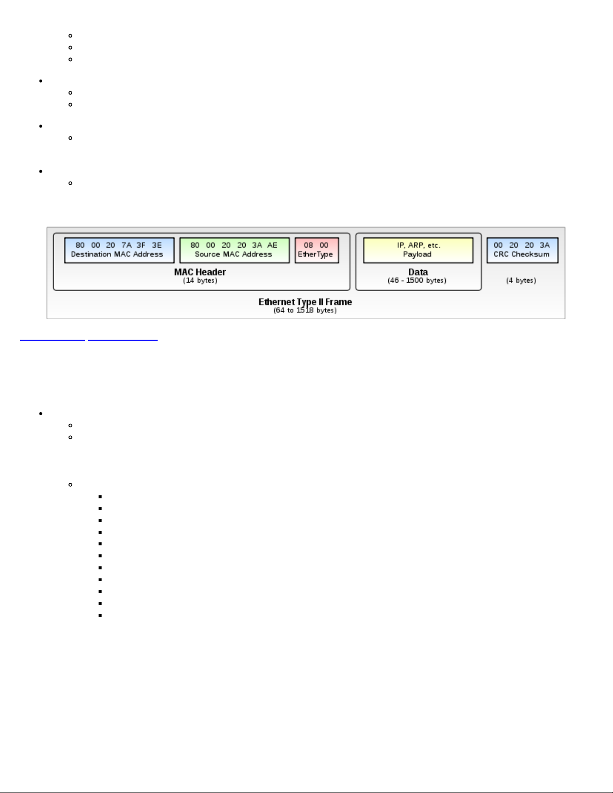
The most common Ethernet Frame format, Type II
Go back to top Go back to ToC
MAC, VLAN, MPLS, IP, and Test Pattern Configurations:
To configure the MAC addresses, IP addresses, VLAN tag(s), MPLS tag(s), and test pattern, tap on the frame image displayed on
the screen. This brings you to the configuration screens for all the header fields.
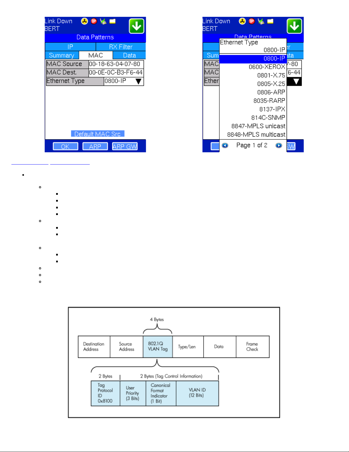
MAC Header Tab:
MAC Source: Use the default source address of the test set or configure a new or different address.
MAC Destination: Configure the destination MAC address of the far-end partner test set or use the ARP or ARP GW
keys to determine the MAC address of the destination IP address (ARP) or the Gateway (ARP GW). Note that a valid
IP connection needs to be up to use these functions. Refer to section 5.1 IP in the V100+ Common Functions
manual for details on IP connection.
Ethernet Type: For Layer 3 and 4 testing, the user can also configure the Ethertype:
0800-IP (Internet Protocol Version 4, IPv4)
0600-Xerox
0801-X.75 (X.75 Internet)
0805-X.25 (X.25 Level 3)
0806-ARP (Address Resolution Protocol [ARP])
8035-RARP (Reverse Address Resolution Protocol [RARP])
8137-IPX (Novell IPX)
814C-SNMP
8847-MPLS unicast
8848-MPLS multicast
86DD (Internet Protocol, Version 6 [IPv6]) - Future Release
BERT Setup - MAC Address Settings (Layer 3) BERT Setup - Ethertype Settings (Layer 3)
Go back to top Go back to ToC
MX100e+/MX120e+ e_Manual D07-00-050P RevD00
Page 27 of 115
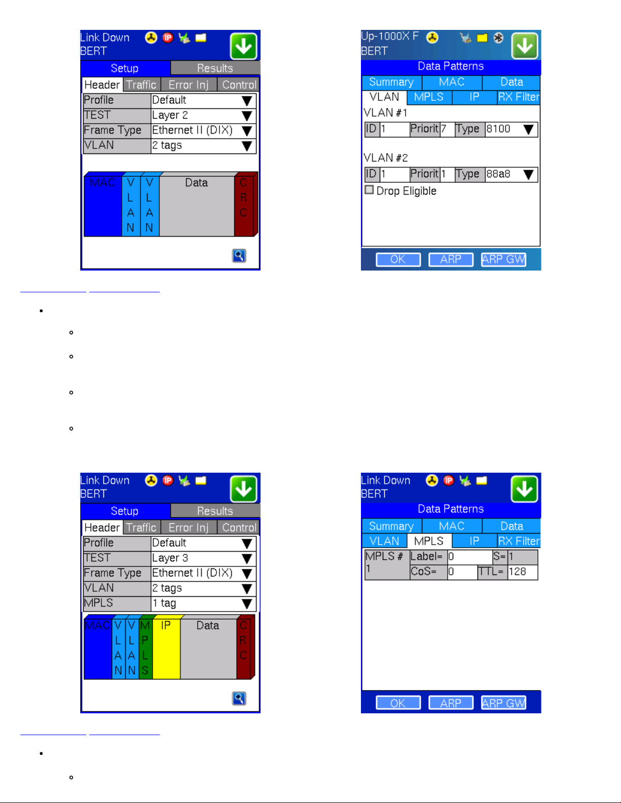
VLAN Tab: In the VLAN tab the following parameters are configured:
VLAN ID: Can be configured in the range 1 to 4094.
VLAN ID is the identification of the VLAN, which is basically used by the standard 802.1Q.
It has 12 bits which allows the identification of 4096 (2^12) VLANs.
Of the 4096 possible VIDs, a VID of 0 is used to identify priority frames and value 4095 (FFF) is reserved.
Maximum possible VLAN configurations are therefore set to 4094.
VLAN Priority: Can be configured in the range 0 to 7.
Set by the Priority Code Point (PCP), a 3-bit field which refers to the IEEE 802.1p priority.
It indicates the frame priority level from 0 (lowest) to 7 (highest), which can be used to prioritize different
classes of traffic (voice, video, data, etc.).
Type: The following selections are possible:
8100 (IEEE 802.1Q tagged frame)
88a8 (IEEE 802.1ad Provider Bridging)
Drop Eligible: If enabled, drop eligibility flag will be set.
VLAN Flooding: Enable/Disable.
VLAN Flooding Range: Specifies the number of VLAN IDs. Enter a number from 0-4096. The VLAN IDs will be
incremented by 1 until it reaches the number of times entered in the flood range.
IEEE 802.1Q VLAN Tag in an Ethernet Frame
BERT Setup - VLAN Tag Configuration BERT Setup - VLAN Tag Summary
Go back to top Go back to ToC
IP Type:
MX100e+/MX120e+ e_Manual D07-00-050P RevD00
Page 28 of 115
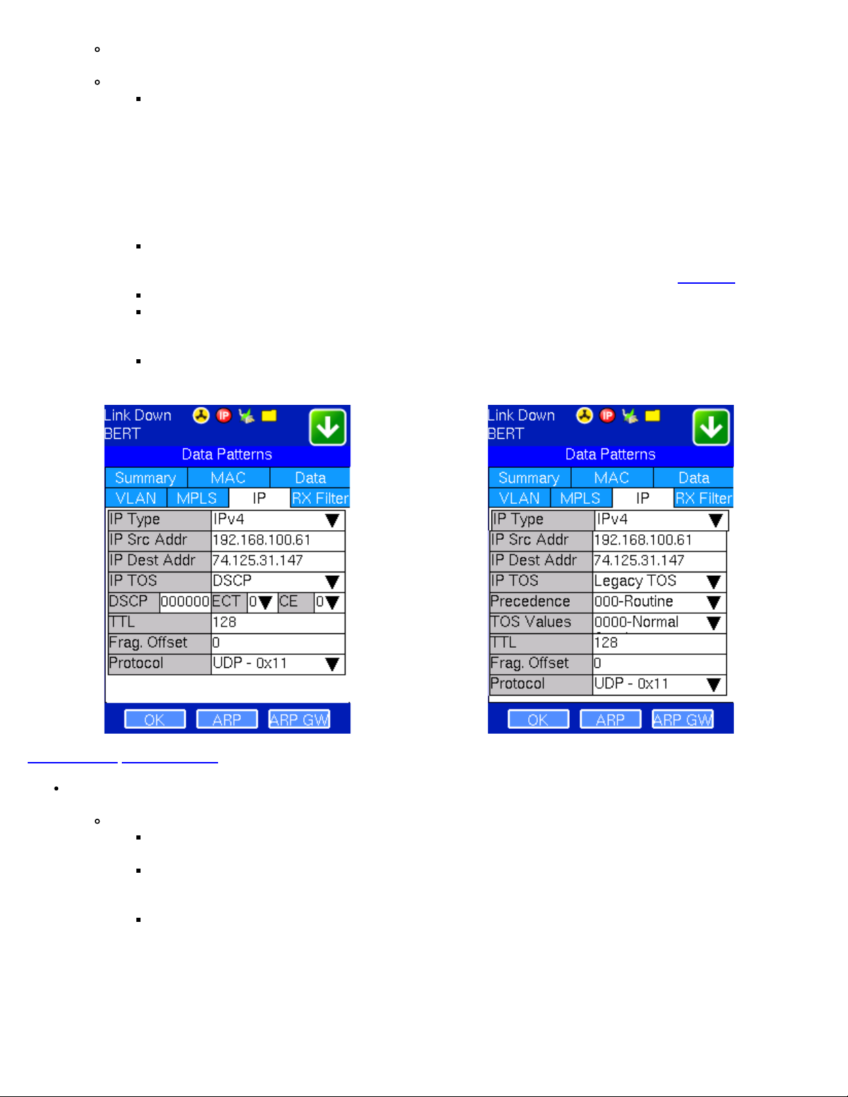
MPLS Tab: In the MPLS tab the following parameters are configured:
MPLS label: Can be configured in the range 16 through 1,048,575 (labels 0 to 15 are reserved).
Note: Composed of 20 bits which allows for the creation of over one million labels.
CoS: Can be configured in the range 0 to 7.
Note: This field is three bits in length and maps directly to IP Precedence TOS bits to provide Class of Service
(COS).
S-bit: Can be configured 0 or 1.
Note: The S field is one bit in length and is used for stacking labels. This is important as it is used to indicate the last
label in the label stack.
TTL: Can be configured in the range 0 to 255. The default setting is 128 hops.
Note: Used to decrement the time-to-live counter.
BERT Setup - Header with MPLS Label BERT Setup - MPLS Label Summary
Go back to top Go back to ToC
IP Tab: In the IP tab the user must configure the destination IP address and source address. The user may also configure
the following IP header fields:
IPv4
IP Src and IP Dest: For IP Src, if the IP connection is up, refer to section 5.1 IP in the V100+ Common Functions
manual. The source address is fixed to the IP address from the IP setup menu.
MX100e+/MX120e+ e_Manual D07-00-050P RevD00
Page 29 of 115
IP TOS (for Quality of Service testing):
Legacy TOS (Precedence): The first three bits of the IP TOS field can be edited:
000 - Routine
001 - Priority
010 - Immediate
011 - Flash
100 - Flash Override
101 - Critical
110 - Internetwork Control
111 - Network Control
DSCP (Differentiated Services Code Point): The first six bits of the IP TOS can be edited to provide more
granular service classification.
For more information on the definition of DSCP field in IPv4 and IPv6 headers, refer to
RFC2474.
Time To Live (TTL): Can be configured in the range 0 to 255.
Fragment offset byte: Can be configured in the range 0 to 65.528.
Note: The fragment offset field, measured in units of eight-byte blocks, is 13 bits long and specifies the offset
of a particular fragment relative to the beginning of the original unfragmented IP datagram.
Protocol field: UDP (0x11), TCP (0x06), or User defined.
BERT Setup - IP Settings (DSCP ) BERT Setup - IP Settings (Legacy TOS )
Go back to top Go back to ToC
Data Tab: User selects a test pattern that will be encapsulated in the Ethernet frame payload (for framed mode).
Depending on the test layer, different test pattern options are available:
Layer 1 test patterns
CRPAT: Compliant Random Pattern provides broad spectral content and minimal peaking for the
measurement of jitter at component or system level.
CJTPAT: Compliant Jitter Test Pattern is a Jitter Tolerance Pattern that stresses a receiver by exposing it to
extreme phase jumps thereby stressing the Clock Data Recovery (CDR) circuitry. The pattern alternates
between repeating low transition density patterns and repeating high transition density patterns.
CSPAT: Compliant Supply Noise Pattern. Represents worst case power supply noise.
BERT Setup - Test Pattern (Layer 1 Unframed ) BERT Setup - Test Pattern (Layer 1 Framed )

Go back to top Go back to ToC
MX100e+/MX120e+ e_Manual D07-00-050P RevD00
Page 30 of 115
Layer 2,3, & 4 test patterns
PRBS:
2^31 -1 (147 483 647-bit pattern used for special measurement tasks, e.g., delay measurements at
higher bit rates)
2^23 -1 (8 388 607-bit pattern primarily intended for error and jitter measurements at bit rates of 34 368
and 139 264kbit/s)
2^15 -1 (32 767-bit pattern primarily intended for error and jitter measurements at bit rates of 1544,
2048, 6312, 8448, 32 064 and 44 736kbit/s)
2^11 -1 (2047-bit pattern primarily intended for error and jitter measurements on circuits operating at bit
rates of 64kbit/s and N x 64kbit/s)
Fixed: All 0s or All 1s
User Defined pattern: Length depends on frame size
Inversion: Normal or inverted
BERT Setup - PRBS Patterns (Page 1)
BERT Setup - MR Pattern (MX100e+ only) (Page 3)
BERT Setup - Special Patterns
(Page 2)
 Loading...