


MTT-14B e_Manual D07-00-083P RevA00
Page 2 of 101
WARNING
U
sing the supplied equipment in a
impair the
CAUTIONS!
•
Do not remove or insert the module while the test set is on. Inserting
•
Do not remove or insert the software cartridge while the test set is on. Oth
End of Life Recycling and Disposal Information
DO NOT dispose of Waste Electrical and Electronic Equipment
unsorted municipal waste. For proper disposal return the product to VeEX
Inc.
to arrange the return and recycling of any of our
protection provided
removing a module with the power on may damage the module.
erwise, damage could occur to the
. Please contact
our local offices or
manner
by the
not specified by
equipment.
cartridge.
service centers
products.
VeEX Inc. may
(WEEE)
for information
on
or
-
as
how
Phone: +1 510 651 0500
E-mail: customercare@veexinc.com
Website: www.veexinc.com
EC
Directive
The Waste Electrical and Electronic Equipment Directive aims to minimize the
impact of the disposal of electrical and electronic equipment on the
environment. It encourages and sets criteria for the collection, treatment,
recycling, recovery, and disposal of waste electrical and electronic equipment.
on
Waste Electrical and Electronic Equipment
(WEEE)
© 2015 VeEX Inc. All rights reserved.
device uses software
This
from third
protected
sors. The purchaser of this device agrees that it has received a license solely
use
copying, reverse engineering, decompiling,
parties.
The
by
copyright
the software as embedded in
either
software
and
contains
developed
is
confidential
trade
the device,
by
VeEX
and
proprietary.
secrets
of
and the
or
purchaser is prohibited from
disassembling
or
VeEX
licensed
The
or
VeEX’s
the
software.
by
VeEX
software is
licen
to
-

MTT-14B e_Manual D07-00-083P RevA00
Page 3 of 101

MTT-14B e_Manual D07-00-083P RevA00
Page 4 of 101
1 SHDSL Module ...................................................................5
1.1 Connector Panel................................................................5
LEDs
1.2
..................................................................................6
2 SHDSL Menus .....................................................................7
2.1 Test
Configuration
2.2 STU-C and STU-R
.............................................................8
Configuration
......................................8
2.2.1 Modem Status ................................................................9
2.2.2 Alarm Status .................................................................11
2.2.3 Modem Control ............................................................12
2.2.3.1
SHDSL
System Loopback
Control ............................12
2.2.3.2 System Settings ........................................................13
2.2.4 PING
Setup/Test...........................................................14
2.2.4.1 LLC-Bridge and Routed Mode Setup .......................15
2.2.4.2 CLIPoA Setup............................................................17
2.2.4.2.1 LLC-BRG,
LLC-RTE,
and CLIP Mode
PING
Results18
2.2.4.3 PPPoA and PPPoE Mode Setup ...............................20
2.2.4.3.1 Entering a User ID/Password .................................22
2.2.4.3.2 PPPoA and PPPoE Mode PING
2.2.4.4
Profile ........................................................................24
Results
................23
2.2.5 Advanced Features ......................................................25
2.2.5.1 ATM
Features
2.2.5.1.1 VCC
Scan
............................................................25
...............................................................25
2.2.5.1.2 OAM Cell Generation .............................................29
2.2.5.1.3 OAM Cell Statistics ................................................31
2.2.5.2 IP
2.2.5.2.1
Features
Configuration
................................................................33
..........................................................33
2.2.5.2.2 IP Status .................................................................39
2.2.5.2.3 PING Test ...............................................................43
Route
2.2.5.2.4 Trace
2.2.5.2.5 Echo
Response
2.3 STUC E1, STUR E1, and E1
............................................................45
......................................................46
Configuration
.....................47
2.3.1 Modem Status ..............................................................50
2.3.2 Alarm Status .................................................................52
2.3.3 E1 Measurement ..........................................................53
2.3.3.1 Measurement
Definitions
...........................................54
2.3.3.2 E1 Measurement Screens .........................................56
2.3.4 Test Pattern ..................................................................59
2.3.4.1 Custom Pa
tterns .......................................................61
2.3.5 Error Injection ...............................................................62
2.4 View/Store/Print ..............................................................64
Test
2.4.1 Saving a
2.4.2 Viewing a Stored
................................................................65
T
est ...................................................65

MTT-14B e_Manual D07-00-083P RevA00
Page 5 of 101
2.4.3 Printing a Stored Test ...................................................65
Test
2.4.4 Deleting a Stored
2.4.5 Locking and Unlocking a
2.4.6 Renaming a Stored
Pr
ofiles
3
Applications
3.1 Loop
2.5
.............................................................................67
......................................................................69
Prequalification
3.2 STU-R Emulation-ISP Service.........................................69
3.3 STU-R
Emulation-Private
3.4 STU-C Emulation.............................................................70
3.5 Accept a New E1 Circuit .................................................71
3.6 In-Service E1 Circuit Monitoring .....................................72
3.7 Measuring E1 Signal
3.8 V.54
3.9 Nx64 kbit/s
Channel Loopback
T
esting
4 Reference ..........................................................................77
T
4.1 PING
echnology.............................................................77
4.1.1 Classical IP over ATM (CLIPoA)....................................78
4.1.2 Ethernet Frames over ATM
4.1.3 PPP over Ethernet
4.1.4 PPP over ATM (PPPoA) ...............................................79
4.1.5 PING Acronyms ............................................................80
4.2 E1 Technology
Overview
4.2.1 Technical Standar
4.2.2 Basic
Definitions
4.2.3 Converting a Voice Signal ............................................81
4.2.4 2.048 Mbit/s Data Rate ................................................82
4.2.5 Line Coding ..................................................................83
4.2.6 Signal Levels ................................................................84
4.2.7 2.048 Mbit/s Framing ...................................................85
5 General Information ........................................................91
5.1 Testing and
Calibration Statement
5.2 Express Limited Warranty ...............................................91
Index
.......................................................................................93
..................................................65
Stored
T
est ...............................................65
Test ..........................65
......................................................69
Network
Level
..............................................73
Service
.....................70
Test ...........................................74
..........................................................75
(EoA)
.................................78
(PPPoE)
over ATM..........................79
.................................................81
ds
.....................................................81
...........................................................81
..................................91

MTT-14B e_Manual D07-00-083P RevA00
Page 6 of 101
The SHDSL
emulation includes STU-R, STU-C, STUC E1, STUR E1, an
E1
emulation
system loopbacks
1.1 Connector Panel
module provides
to verify link
turn-up,
for troubleshooting.
SHDSL
modem emulation. Modem
read
performance
data, and
d
The module panel contains:
PAYLOAD: RJ-45 port for E1
STU: RJ-45 port (for SHDSL testing) Pin out for the STU
pair one is 4 and 5, pair two is 7 and 8.
PAYLOAD STU
Figure 1 Connector
testing.
Panel
port:

MTT-14B e_Manual D07-00-083P RevA00
Page 7 of 101
1.2 LEDs
SSMTT-ACM, -ACM+, -EX
Figure 2 Test Set LED
SSMTT-B,
Panels
The module uses the following test set LEDs:
MODULE
•
Green: Indicates that the test set is using the module.
xTU-C
•
•
xTU-R
•
•
Green:
Indicates
Blinking Red:
up.
Green:
Indicates
Blinking Red:
up.
that the
Indicates
that the
Indicates
module
that the
module
that the
is linked up as
module
is
attempting
is linked up as
module
is
attempting
LP1 SYNC
•
Green: When link is
•
Red: When link is not
established
established
with far end
with far end
device.
device.
ALARM
•
Red: Indicates that the module has detected an alarm.
-C
STU-C.
to link
STU-R.
to link

2.3.4
TEST
PATTERN
2.3.5
VIEW/STORE/PRINT
2.2.5.2.1
2.2.5.2.2
IP STATUS
2.2.5.2.4
2.2.5.2.5
ECHO RESPONSE
MTT-14B e_Manual D07-00-083P RevA00
Page 8 of 101
The following figure
STU-C or STU-R
2.2
TEST
CONFIGURATION
2.2.1
MODEM STATUS
2.2.2
ALARM STATUS
2.2.3
MODEM
2.2.4
PING
2.2.5
ADVANCED
2.4
VIEW/STORE/PRINT
2.5
PROFILES
2.2.3
MODEM
2.2.3.1
LOOPBACK
2.2.3.2
SYSTEM SETTINGS
CONTROL
SETUP/TEST
FEATURES
CONTROL
CONTROL
2.2.5
ADVANCED
2.2.5.1
2.2.5.2
ATM
FEATURES
IP
FEATURES
FEATURES
2 SHDSL Menus
shows
the location of major menu
2
MAIN
2.1
TEST
2.3
STUC E1 or STUR E1
TEST
2.3.1
MODEM STATUS
2.3.2
ALARM STATUS
2.3.3
E1 MEASUREMENT
2.3.4
TEST
2.3.5
ERROR
2.3.6
MODEM CONTROL
2.4
VIEW/STORE/PRINT
2.5
PROFILES
2.3.6
MODEM CONTROL
2.3.6.1
LOOPBACK CONTROL
2.3.6.2
SYSTEM
MODULE
KEY
MENU
CONFIGURATION
CONFIGURATION
PATTERN
INJECTION
SETTINGS
2.3
2.3.3
2.4
2.5
items.
E1
TEST
CONFIGURATION
E1 MEASUREMENT
ERROR
INJECTION
PROFILES
2.2.5.2
IP FEATURES
CONFIGURATION
2.2.5.2.3
PING TEST
TRACE
ROUTE
2.2.5.1
ATM
FEATURES
2.2.5.1.1
VCC
SCAN
2.2.5.1.2
OAM CELL
2.2.5.1.3
OAM CELL STATISTICS
GENERA
TION
Figure 3 Module Menu Tr
ee

MTT-14B e_Manual D07-00-083P RevA00
Page 9 of 101
2.1 Test
MODE
MODE
Options: STU-C
F1),
Select
Configuration
determines
the
(F1),
E1 (more, F2)
the
proper operating mode
displayed configuration
STU-R
(F2), STUC E1 (F3), STUR E1 (more,
for the circuit to be
scr
een:
tested.
08:39:57
>LINK DN- Idle 4W
TEST
CONFIGURATION
MODE : STU-C
WIRES : 4-WIRE
PL RATE : 2304K X2
LN RATE : 2312K X2
STANDARD : ANNEX-A
2.2 STU-C and STU-R
Configuration
STU-C<
08:39:57
>LINK DN- Idle 4W
TEST
CONFIGURATION
MODE : STU-R
WIRES : 4-WIRE
PL RATE : 2304K X2
LN RATE : 2312K X2
STANDARD : ANNEX-A
STU-R<
STU-C STU-R STUC-E1 more STU-C STU-R STUC-E1 more
Configure
Figure
the
4 STU-x
following:
Configuration
Scr
eens
WIRES
(F1),
Options: 2-WIRE
Select
the type of line that the test set
4-WIRE (F2)
will
be
connected to.
PL RATE (Payload Rate)
Options:
(more
1024K
(more, F3),
AUTO (F1),
, F2), 384K (more, F3), 512K (more, F1), 768K (more, F2),
(more
, F3), 1152K (more, F1), 1280K (more, F2), 1536K
2048K (more, F1), 2304K (more, F2)
128K
(F2),
192K
(F3),
256K (more, F1), 320K
Manually choose the Payload Rate or press F1 to let the test set
automatically select the correct rate.
LN RATE (Line Rate)
Options:
(more
1032K
(more, F3),
Manually c
AUTO (F1),
, F2), 392K (more, F3), 520K (more, F1), 776K (more, F2),
(more
, F3), 1160K (more, F1), 1288K (more, F2), 1544K
2056K (more, F1), 2312K (more, F2)
hoose the Line Rate or press F1 to let the test set
136K
(F2),
200K
(F3),
264K (more, F1), 328K
automatically select the correct rate.
Notes for Payload and Line Rates:
•
PL Rate
head. The difference
configuration
and LN
Rate are related. Line Rate
between
is modified, the other one
is
inclusive
of over-
the two are 8K. Whenever
will
also be
modified.
one
MTT-14B e_Manual D07-00-083P RevA00
Page 10 of 101
•
For single ended applications, i.e., STU-R emulation
with a DSLAM, use a fixed rate that
matches
the
testing
expected
commercial service rate.
STANDARD (per ITU G.991.2)
Options:
ANNEX-A (F1),
Select an operating standar
•
ANNEX-A:
operating
•
ANNEX-B:
operating
Describes specifications
under North American network
Describes specifications
under
ANNEX-B (F2)
d.
European
network
for G.SHDSL
conditions.
for G.SHDSL
conditions.
systems
systems
Press ESC to return to the main menu.
2.2.1 Modem Status
Use
these screens
to view the available
08:39:57
>LINK UP 4W STU-R<
ET: 000:05:54
LINE RATE :1544 kbps X 2
PAYLOAD RATE:1536 kbps X 2
CH1 - STU-C STU-R
CUR SNR MARGIN: 18 dB 16 dB
ATTENUATION : 1 dB 1 dB
CH2 -
CUR SNR MARGIN: 18 dB 16 dB
ATTENUATION : 1 dB 1 dB
MODEM STATUS
PRINT STORE RESET
Modem Status screens
provide general performance
information on the STU-C
and STU-R. For the far end
data, “N/A” is displayed.
Note that CH2 status screen
information is only available
in 4-wire
mode.
to view real time link
scr
eens.
RETRAIN
parameters. Press
08:39:57
>LINK UP 4W STU-R<
ET: 000:05:54
RETRAINS: 0
CH1 - STU-C STU-R
MAX SNR MARGIN : 19 dB 18 dB
MIN SNR MARGIN : 16 dB 13 dB
CRC ERRORS : N/A 0
ERROR SEC : N/A 0
SEVERE ERR SEC : N/A 0
UNAVAILABLE SEC: N/A 0
LOSW SEC : N/A 0
PRINT STORE RESET
08:39:57
>LINK UP 4W STU-R<
ET: 000:05:54
RETRAINS: 0
CH2 - STU-C STU-R
MAX SNR MARGIN : 19 dB 18 dB
MIN SNR MARGIN : 16 dB 13 dB
CRC ERRORS : N/A 0
ERROR SEC : N/A 0
SEVERE ERR SEC : N/A 0
UNAVAILABLE SEC: N/A 0
LOSW SEC : N/A 0
PRINT STORE RESET RETRAIN
MODEM STATUS
RETRAIN
MODEM STATUS
Figure 5 Modem Status Screens
ET: Elapsed Time since
pr
essed.
LINE
RATE
reported
and Line Rates.
PAYLOAD RATE
Payload and
Line Rates.
RESET
in
kbps,
reported
(F3),
RETRAIN
(F4), or ESC is
see Section 2.2-Notes for Payload
in
kbps,
see Section 2.2-Notes
for

MTT-14B e_Manual D07-00-083P RevA00
Page 11 of 101
CUR SNR MARGIN: Current signal-to-noise margin (in dB) is
the maximum dB increase in equalized noise or the maximum
dB decrease in equalized signal that a system can tolerate and
-7
maintain a BER of 10
.
ATTENUATION: This displays the loop attenuation (in dB).
MAX SNR MARGIN: Maximum signal-to-noise margin (in dB)
(F4)
measured during ET. When either RETRAIN
or ESC is
pressed, MAX SNR is reset.
(
in dB
MIN SNR MARGIN: Minimum signal-to-noise margin
that is measured during ET. When either
RETRAIN (F4)
or ESC
)
is pressed, MIN SNR is reset.
CRC ERRORS: Count of CRC errors and is reset when ET is
reset.
ERROR SEC: Count of 1 second intervals during which one
more
CRC
errors
are
declared and/or one or more
LOSW defect
or
s
are declared. Reset when ET is reset.
SEVERE
least 50 CRC errors are declared or 1 or more
ERR SEC: Count of 1 second intervals during which
LOSW
defects are
at
declared. 50 CRC errors during a 1 second interval is equivalent
to a 30% error frame rate for a normal frame length. Reset when
ET is reset.
UNAVAILABLE
SHDSL
line is unavailable.
at the onset of 10 contiguous
unavailable time.
the
available at the
The 10
seconds with
SEC: Count of 1 second intervals for which the
The SHDSL line
SESs. The
Once unavailable,
onset
of 10
contiguous seconds
no SES are excluded
becomes unavailabl
10
SESs are
included in
the SHDSL line becomes
with no
SESs.
from unavailable time
e
.
Reset when ET is reset.
LOSW SEC: Loss of synchronization word second is a
count
of 1 second intervals during which one or more SHDSL LOSW
defects are declared. Reset when ET is reset.
The following F-keys are
PRINT
STORE
RESTART
RETRAIN
(F1):
Send the status screens to the serial
(F2):
Press to store the status screen.
(F3):
Restarts polling and resets ET to zero.
(F4):
Retrains the modem and resets ET to zero.
common
to
these
screens:
port.

R<
curr hist curr
hist
CH1 -
ATTN: NO NO NO NO
CH2 -
ATTN: NO NO NO NO
MTT-14B e_Manual D07-00-083P RevA00
Page 12 of 101
2.2.2 Alarm Status
This screen
general alarm
(current and history
local and remote).
Note CH2 is r
only in 4-wire
pr
ovides
status
eported
mode.
for
08:39:57
>LINK UP 4W STU-
SNR : NO NO NO NO
LOSW: NO NO NO NO
ALARM STATUS
LOCAL
REMOTE
SNR : NO NO NO NO
LOSW: NO NO NO NO
PRINT STORE
Figure 6 Alarm Status Screen
This screen reports the
Triggered when the local current
SNR:
following:
the user threshold setting. This is set in MODEM CONTROL
SYSTEM SETTINGS,
on the SNR MARGIN
LOSW: Loss of Sync defect
SNR margin value is below
THRESHOLD
alarm,
a loss of synchronization wor
>
line.
d
defect is declared when at least 3 consecutive received frames
contain 1 or more errors. An LOSW defect is cleared when
at
least 2 consecutive received frames contain no errors.
ATTN: Triggered when the local attenuation value is greater than
tory.
the
>
the user threshold value. This is set in MODEM CONTROL
SYSTEM SETTINGS,
on the LOOP ATTN
THRESHOLD
line.
These alarm conditions are displayed as current and his
These
are
defined
curr YES: The alarm condition is currently
curr NO: The alarm condition is not currently
hist YES: The alarm
pr
longer
esent.
hist NO: The alarm
as:
condition
condition
has
been detected,
has never
detected.
detected.
but it is no
been detected
since
start of the test or since pressing HISTORY.
The following F-keys are
(F3):
PRINT
STORE
Send the alarm screen to the serial
(F4):
Press to store the status screen.
available:
port.

MTT-14B e_Manual D07-00-083P RevA00
Page 13 of 101
2.2.3 Modem Control
This menu contains the
•
LOOPBACK CONTROL
•
SYSTEM
SETTINGS
2.2.3.1 SHDSL System Loopback Control
08:39:57
>LINK UP 4W STU-R<
SHDSL SYSTEM LOOPBACK
STU-C STU-R
T
R
COMMAND :
STATUS :
This
line
the EOC. They are:
LOOP-DN
LOOP-DN and the
STATUS
STU-C C (F2): Use this to
tomer. This will cause the COMMAND line to change to STU-C
C and the
line will report either
ACTION.
STU-R N (F
work. This will
N and the
line will report either
ACTION.
LOOP-DN STU-C C STU-R N
Figure 7 SHDSL System Loopback Screen
screen displays
used
to enter different
(F1):
This will cause the COMMAND line to change
line will report either
appropriate
3): Use this to
cause
appropriate
following:
a loopback graphic. It includes
types
of
loopback messages
appropriate
EOC
EOC
SUCCESS
loopback
message
message
will be
or FAIL.
the STU-C, facing the
will be
sent.
WAITING, FAILED, SUCCESS,
loopback
the COMMAND line to
EOC
message
the STU-R, facing the
change
will be
sent.
WAITING, FAILED, SUCCESS,
a COMMAND
sent
via
to
sent. The
cus
The STA
TUS
or ILLEGAL
net
to
STU-R
The STA
TUS
or ILLEGAL
-
-

MTT-14B e_Manual D07-00-083P RevA00
Page 14 of 101
2.2.3.2 System Settings
DISPLAY ALL EOC MESSAGES
Use this screen to adjust the defaults
•
ON: will display far end values for CRC, SES, ES, UAS, and
(if
LOSW
this
•
OFF:
available). At this time, the
mode.
is the default.
SNR MARGIN THRESHOLD
Adjust by using +1 (F1) or -1 (F2). The
adjusted between
than this
setting,
-15
through
then the
+15 dB.
ALARM
LOOP ATTEN THRESHOLD
Adjust by using +1 (F1) or -1 (F2). The
adjusted from 1–127. The default setting is
exceeded,
then the
ALARM
LED
RECEIVE EOC SNR OFFSET
For reporting via the EOC (for STU-C/R only).
•
ON: for far end sending SNR raw values to near end.
•
OFF:
for far end sending
SNR
is the default.
SEND EOC SNR OFFSET
For reporting via the EOC (for STU-C/R only).
•
ON: for near end sending SNR margin values to far end. ON
is the default.
•
OFF:
for near end sending SNR raw values to far end.
TRANSFORMER RATIO
•
ON: the transformer ratio is set to 5:4:1. ON is the default.
•
OFF:
the transformer ratio is set to 4:1.
If
the
CAUTION:
ent
between
reported
the STU-R and STU-C,
loop
ratio used is the same.
press
When finished
ENTER to
for:
module does
threshold
If
the SNR margin is
LED
will
threshold
will
be
on.
margin
values
attenuation
ensure
update
and save the
not
support
can be OFF,
be
on.
can be OFF,
OFF.
If this setting is
to
near
end. OFF
is significantly dif
that the
transformer
changes.
or
less
or
fer
-

MTT-14B e_Manual D07-00-083P RevA00
Page 15 of 101
2.2.4 PING
Link
turn-up verifies connectivit
the
turn-up procedure
to the far end
whether two remote LAN segments using TCP-IP protocol are
connected. When receiving a PING message, Internet devices
acknowledge
turning
After
ule main menu. The first
the PING test. Enter the
well as the
Notes:
•
Before
lished.
•
To enter
If
available,
MODE
Options: PROFILE
CLIPoA (more,
Select the prot
•
PROFILE: Use to store and retrieve PING
Section 2.2.4.4.
•
LLC-BRG: LLC-Bridge protocol. This follows RFC 1483 bridge
encapsulation.
agement.
•
LLC-RTE: LLC-Routed protocol. It supports only static IP
addr
•
CLIPoA: This refers to Classical IP over ATM according to
RFC 2225. Used only in
•
PPPoE:
PPP over Ethernet.
•
PPPoA: PPP
over AAL5. PPPoA
actual configuration settings depend
The
hence
for each
Setup/
up the link,
Test
network.
it by
sending
y to a
one
step
further and verifies
PING is a
an
echo message back.
enter PING
DSLAM. PING testing takes
common method
SETUP/TEST from the mod-
screen contains configuration
proper protocol used
necessary
performing
numbers, press
use <-,-> to move the
IP
addresses.
The first
setting
a PING test, confirm that the link is
SHIFT and use the numeric
cursor.
(F1),
LLC-BRG
F2),
PPPoE (more,
ocol mode for the PING
(F2),
F1),
LLC-RTE (more, F1),
PPPoA
test.
configurations,
It
essing.
supports
both static and
STATIC
mode.
PPP over Ethernet, according to standard
PPPoE
over
ATM, according
supports
supports dynamic IP addressing.
to
standard RFC 2364,
dynamic
IP addressing.
on the
the following subsections describe setup
mode.
connectivity
to
discover
items
by the circuit,
is MODE.
estab
keypad.
(F2,
more)
dynamic
IP
RFC
man
2516
PPP
selected mode,
and PING result
see
for
as
-
-
s

MTT-14B e_Manual D07-00-083P RevA00
Page 16 of 101
2.2.4.1 LLC-Bridge and Routed Mode Setup
11:50:50
>LINK UP 4W STU-R<
PING SETUP
MODE :LLC-BRG
ENCAPSULATION :LLC
:8
VPI
VCI
IP ADDRESS
:35
:STATIC
LOCAL IP :207.181.199.178
DESTINATION IP:207.181.199.177
GATEWAY :207.181.199.177
PROFILE LLC-BRG
LLC-RTE CLIPoA
PPPoE PPPoA
START more
START more
START more
Configure
ENCAPSULATION
Options: LLC
Choose
Type 5 over ATM.
•
LLC: Logical Link Control based
encapsulation is used when multiple protocol are
lated over a single ATM Virtual Connection.
•
VC
a single ATM Virtual C
•
AUTO: Automatically detect the setting
VPI
Range: 0 through 255
The default is 8, which is a typical Ethernet assignment.
with
through a series of ATM switches on the way to its destination.
The service provider typically assigns VPI.
Figure 8 LLC-BRG PING Setup Screen
these settings for LLC-BRG and LLC-RTE modes:
(F1),
VC MUX
the encapsulation method
(F2),
AUTO (F3)
for carrying traffic over AAL
on IEEE
standard
802.2. LLC
encapsu-
MUX: This is used when only one protocol is carried over
onnectio
n.
.
Along
VCI, VPI identifies the next destination of a cell as it moves

MTT-14B e_Manual D07-00-083P RevA00
Page 17 of 101
VCI
Range: 0 through 65535
The default is 35, which is a typical Ethernet assignment. Along
VCI
with VPI,
identifies the next
through a series of ATM switches on the way to its destination.
The service provider typically assigns VCI.
IP ADDRESS
Options:
•
•
STATIC (F1),
STATIC:
a
permanent
will
This type of
be the value
DHCP: This refers to dynamic IP management. If selected,
IP
address.
used
DHCP (F2)
IP
enter the IP address for the destination.
Dynamic management provides
protocol configuration parameters
dynamically from the
network.
not permanent to the terminal; instead, the terminal requests
address
an
DYNAMIC for IP
from the server on the
ADDRESS,
the server; the server responds and provides an IP
Upon selecting
network dynamically
DYNAMIC,
assigns
LOCAL IP
Enter a local IP address of the circuit under test. For LLC-BRG
static mode and LLC-RTE, this is the local IP address us
For LLC-BRG DHCP mode, there is no LOCAL IP mode since a
dynamically assigned local IP address is used.
DESTINATION IP
Enter the
destination address
ing a gateway, enter the gateway’s address for the Destination
IP.
Pinging the
gateway
verifies
GATEWAY
If required, enter a gateway address. A gateway is a device
connects
dissimilar
networks
them. In TCP/IP, the default gateway address is the addre
where the Internet
networks, unless
Protocol sends packets destined
a different route is
is a pure routed mode, there is no gateway setting. This
applies only to LLC-BRG
destination
of a cell as it
moves
management means that the user has
For STATIC, enter
during the
test.
a way for
(like the local IP
In this
the
computers
case,
network.
LOCAL IP;
the IP
address is
When
this
to obtain
address)
selecting
the module sends a request
addr
ess.
the
LOCAL IP
an IP
line disappears; the
addr
ess.
ed.
of the
device
connectivity
to be
pinged.
to the ISP.
If
ping
that
and
passes
information
configured.
between
for r
emote
Since LLC-RTE
setting
mode.
to
-
ss

MTT-14B e_Manual D07-00-083P RevA00
Page 18 of 101
2.2.4.2 CLIPoA Setup
11:50:50
>LINK UP 4W STU-R<
MODE :CLIPoA
ENCAPSULATION :LLC
VPI
VCI
IP ADDRESS :207.181.199.176
LOCAL IP :207.181.199.178
Configure theses settings
ENCAPSULATION
Options: LLC
LLC is the only
VPI
Range: 1 to 255
The default is 8, which is a typical Ethernet assignment. Along
with
through a series of ATM switches on the way to its destination.
The service provider typically assigns VPI.
VCI
Range: 1 to 65535
The default is 35, which is a typical Ethernet assignment. Along
with VPI,
through a series of ATM switches on the way to its destination.
The service provider typically assigns VCI.
LOCAL IP
Enter t
DESTINATION IP
Enter the
LLC-RTE
Figure
encapsulation method available.
VCI,
VPI identifies the next
VCI
identifies the next
he Local IP
Destination
PING SETUP
CLIPoA
9 CLIPoA
for
address
of the circuit to be
IP
address
:8
:35
START more
Configuration
Classical
IP over ATM:
destination
destination
to be
pinged.
Scr
een
of a cell as it
of a cell as it
tested.
moves
moves

MTT-14B e_Manual D07-00-083P RevA00
Page 19 of 101
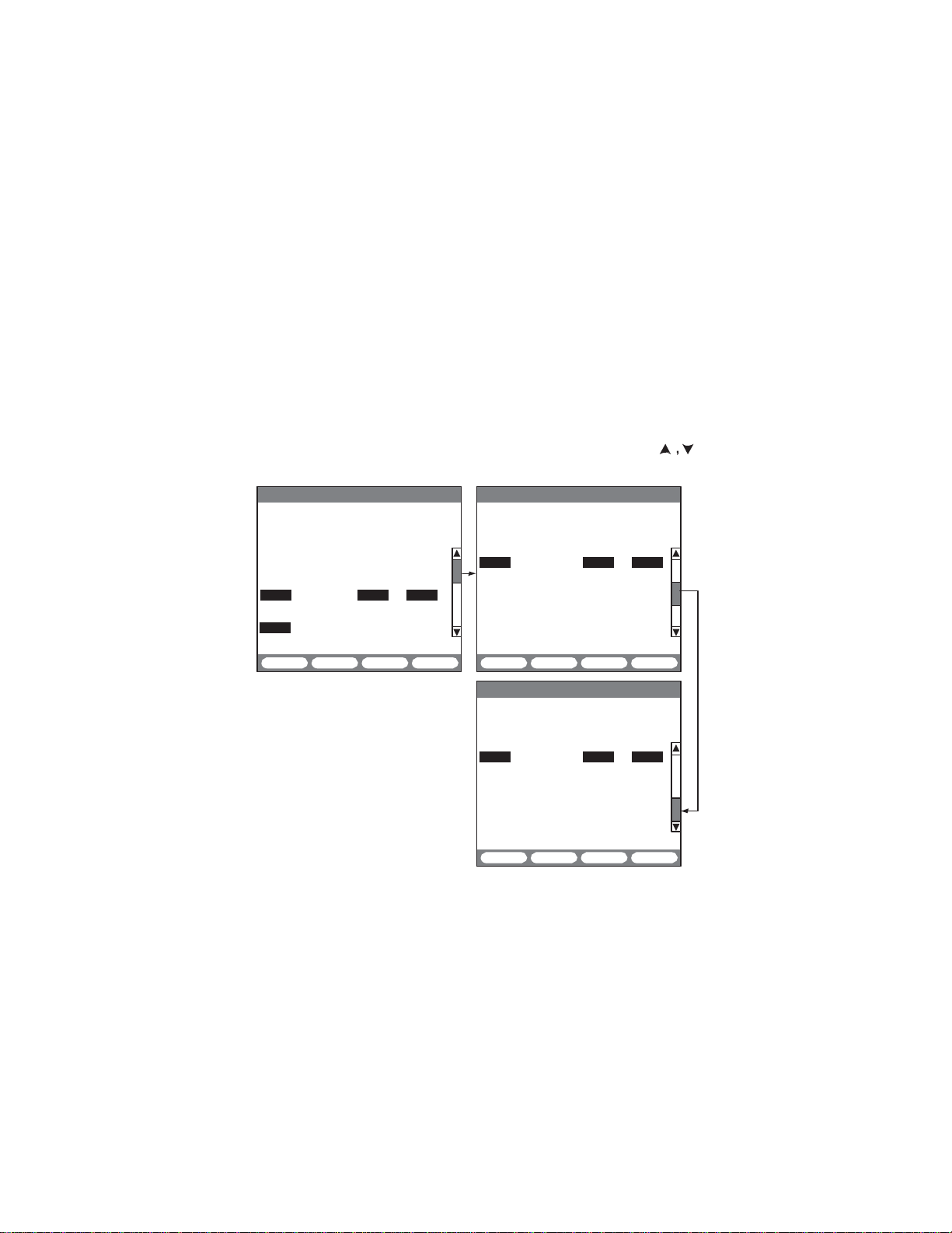
2.2.4.2.1
After
the test set displays an ‘IN
•
The
or more responses from the destination is considered a pass.
Refer to the following figure for a
LLC-BRG, LLC-RTE,
configuring, press
module will send 10
F3 to
and CLIP Mode PING Results
start
the
test. As
PROGRESS’
PINGs
message.
at one-second intervals. One
pass sample.
12:30:55
>LINK UP 4W STU-R<
ST:12:30:10 ET:00:00:45
LOCAL IP:207.181.199.178
DEST IP :207.181.199.177
PING
TEST
PING :
PASS
PING STOP
Figure 10 LLC PING Test
Passed
the
test pro
ceeds
,
•
‘PING PASS’ means the destination has received the PING
message and properly responded to the module. This indicate
that the module can connect to the Internet.
•
If the test set
receives
no response, it will display ‘PING FAIL’.
This indicates that either the destination did not receive the
PING m
•
Press F4 to stop the test, press it again to restart
•
Press F1 to PING the DEST IP again after PING: PASS is
displayed.
In addition to the test results, the screen also r
ET: Elapsed Time since the test was started or restarted.
ST: Start Time of the
essage or it did not reply.
test.
eports:
testing.
LOCAL IP: Provides the local IP address for the module. For
LLC-BRG static and
entered in
the configuration screen.
LLC-RTE,
IP shows all zeros until the DHCP server assigns an IP
When assigned, the LOCAL IP line will display this
DEST IP: Provides the destination IP address for the
sages.
This is
determined
this is the exact
For LLC-BRG DHCP, LOCAL
in the
configuration
LOCAL IP address
addr
addr
ess.
PING mes-
scr
een.
s
ess.

MTT-14B e_Manual D07-00-083P RevA00
Page 20 of 101
If selecting LLC-BRG, DHCP IP ADDRESS, the PING results
screen differs slightly from Figure
assign the local IP address. There are two steps for the results:
1. When the test first begins, the
zeros. As soon as the
updates
and DHCP displays ‘PASS’ as in the following figure:
12:30:55
>LINK UP 4W STU-R<
DHCP server
10. For DHCP, the network must
LOCAL
IP
address
provides an IP address,
line shows all
it
ST:12:30:10 ET:00:00:45
LOCAL
DEST IP
IP:001.002.003.004
:002.003.004.005
PING
TEST
DHCP : PASS
PING :
IN PROGRESS
2. After r
PING messages using the local IP address. When a reply is
eceived, ‘PING PASS’ is displayed
r
Figure 11 DHCP: IP Address Assigned
eceiving an IP address,
the
test set begins transmitting
as in
12:30:55
>LINK UP 4W STU-R<
ST:12:30:10 ET:00:00:45
LOCAL
DEST IP
IP:001.002.003.004
:002.003.004.005
PING
TEST
DHCP :
PING :
PASS
PASS
STOP
the following figure
:
Figure 12 DHCP: PING Passed
START

MTT-14B e_Manual D07-00-083P RevA00
Page 21 of 101
2.2.4.3 PPPoA and PPPoE Mode Setup
PPP (Point-to-Point Protocol) allows one or more user sessions
to tunnel
across
and protocol negotiations.
the link. This
The
includes provisions
for
security
module supports two versions
of
PPP: PPPoE (PPP over Ethernet) and PPPoA (PPP over ATM).
Refer to Section 4.1 for details on these
When
requires negotiation.
selecting
PPP, the network
Refer to the following
security
protocols.
figure:
and
authentication
11:50:50
>LINK UP 4W STU-R<
PING SETUP
MODE :PPPoA
ENCAPSULATION :AUTO
AUTHENTICATION:PAP
VPI :8
VCI :35
IP ADDRESS :DYNAMIC
DESTINATION IP:001.333.452.012
USER ID : *******
PASSWORD : *******
PROFILE
Figure 13 PPPoA PING Setup Screen
LLC-BRG START more
Configure
ENCAPSULATION
Options: LLC
This refers to the Encapsulation
AAL Type 5 over ATM.
•
LLC: Logical Link Control based
encapsulation is used when multiple protocol are
lated over a single ATM Virtual Connection.
•
VC
a single ATM Virtual C
•
AUTO: Automatically detect the setting
Note: When MODE
encapsulation
AUTHENTICATION
Options: PAP
The
lishes
these settings for PPPoA and
(F1),
VC MUX
(F2),
AUTO (F3)
method
PPPoE modes:
for carrying traffic over
on IEEE
standard
802.2. LLC
encapsu-
MUX: This is used when only one protocol is carried over
onnectio
n.
.
is
set
for
PPPoE,
LLC is
the only available
method.
(F1),
CHAP
authentication layer
a connection with the
(F2),
AUTO (F3)
ensures
that only a valid device estab-
network. Choose
the following
:

MTT-14B e_Manual D07-00-083P RevA00
Page 22 of 101
•
PAP:
Password Authentication Protocol
PAP
1334.
two-way handshake
a
and ID to
peer
is the simplest method fo
another
returns
peer
an
authentication-acknowledge message either
where one peer
element
in the
accepting or rejecting the user name and password. When
selecting
the
•
CHAP:
fined in RFC 1994.
PAP, enter the
configuration
scr
een.
password
Challenge Handshake Authentication Protocol
It
involves a
three-way
the test set sends a challenge containing its user name. The
server
responses
transaction.
with a
The
test set then accepts or rejects this response,
specific
identifier
when accepted the test set starts sending data.
•
AUTO: Use
this recommended setting to automatically
the authentication.
VPI
Range: 0 through 255
The default is 8, which is a typical Ethernet customer
ment. Along with
VCI, VPI
identifies the next
as it moves through a series of ATM switches on the way to
destination. The service provider typically assigns VPI.
VCI
Range: 0 through 65535
The default is 35, which is a typical Ethernet customer
ment. Along with VPI,
VCI
identifies the next
as it moves through a series of ATM switches on the way to
destination. The service provider typically assigns VCI.
IP ADDRESS
Options:
•
STATIC:
a
permanent
will
be the value
STATIC (F1),
This type of
DYNAMIC (F2)
IP
IP
address.
used
management means that the user has
For STATIC, enter
during the
test.
• DYNAMIC: This refers to dynamic IP management. If selected
enter the IP address for the
provides
tion
the
a way for
parameters
network.
In this
(like the local IP
destination. Dynamic
computers
case,
the IP
to obtain
address
address)
the terminal; instead, the terminal requests an address
the server on the
network.
When
selecting
ADDRESS, the module sends a request to the server; the
server responds and provides an IP address. Upon select
ing DYNAMIC, the LOCAL IP line
dynamically assigns an IP
addr
ess.
as
defined
r authentication. It
sends
network.
a user
The
and ID at the
handshake,
expected
destination
destination
the
LOCAL IP;
management
protocol
dynamically from
is not
permanent to
DYNAMIC
disappears;
the
in
RFC
involves
name
second
bottom of
as de-
in
which
for
this
detect
assign
of a
cell
its
assign
of a
cell
its
this
configura
from
for
IP
network
-
-
,
-
-

MTT-14B e_Manual D07-00-083P RevA00
Page 23 of 101
LOCAL IP
Enter a local IP address of the circuit under test. For LLC-BRG
and LLC-RTE STATIC, this is the local IP address used. For
LLC-BRG DYNAMIC mode, there is no LOCAL IP mode since a
dynamically assigned local IP address is used.
DESTINATION IP
Enter the
destination address
of the
device
to be
pinged.
If
ping
ing a gateway, enter the gateway’s address for the Destination
IP.
Pinging the
gateway
verifies
connectivity
to the ISP.
USER ID
For
authentication (PAP
and CHAP)
, enter
a user ID
prior to receiv
-
ing an IP address from the ISP. Refer to Section 2.2.4.3.1.
PASSWORD
For authentication
and CHAP)
, enter a password prior to re-
(
PAP
ceiving an IP address from the ISP. Refer to Section 2.2.4.3.1.
2.2.4.3.1 Entering a User
ID/Passwor
Follow this procedure to enter a
HAP authentication.
and C
1. Place the cursor on
2. Press
3. Press
EDIT (F1)
INPUT (F3)
USER
and a character screen is displayed.
to enter the character grid. Notice a cursor
USER ID
ID.
d
or
PASSWORD
for PAP
appears in the grid and INPUT changes to STOP.
4. Use to move the cursor to the desired character.
ENTER
Press
pear on the
5. Continue selecting characters until done. Press
exit the character
•
If
you make a
to select that character. The character will ap
USER
ID line.
STOP (F3)
grid.
mistake; press
STOP (F3). Use to select
-
to
the incorrect character.
- Press
DELETE (F2)
- Press INSERT
to delete the character.
(F1)
to add a character to the left of the
selected character.
- Press
OVER (F1)
to replace the selected character with a
new character.
6. Select HIDE
to hide the ID
13 shows the
code
USER
PASSWORD)
by
pressing
ID and
PASSWORD
and choose whether
YES (F1) or NO (F2).
hidden.
Figure
USER
ID (or
7. Press F4 to save the ID and return to the setup screen.
8. S
elect
PASSWORD
and follow the previous procedure
from
step 2 to enter the password.
-

MTT-14B e_Manual D07-00-083P RevA00
Page 24 of 101
2.2.4.3.2 PPPoA and PPPoE Mode PING Results
After
configuring, press
the test set displays an ‘IN
For PPP PING results there are three stages to the
•
ROUTER:
This stage identi
fies the connection to the
Broadband Remote Access
•
Server
PPP:
or ISP.
Identifies the account
with the ISP and
account verification (with
authentication
established.
•
PING
represents the
connection/response to the
destination IP address.
Reflected
•
ROUTER
in Figure 14 are
- “PASS” means that the module has connected to the
router/broadband access
be to verify
“FAIL”
-
•
PPP
- “PPP: in
means
progress” means
is currently in progress. A local IP address is not yet as-
signed,
as
IP management were selected, the LOCAL IP entered in
configuration screen
the
- “PPP: PASS”
was
successful
as displayed on the LOCAL IP line.
•
PING
- “PING:—” This
as soon as the PPP stage is
-
“PING:
in progress”
process. As soon as the module
destination,
the
no response from the destination, it will display ‘FAIL’.
F3 to
start
PROGRESS’
ensures
enabled)
that
is
these
authentication.
that no
indicated
means
connection
by all zeros for the
that the
and a local IP
stage
has not
means
it will
display ‘PASS’.
the
test. As
the
test pro
message.
test:
-
12:30:55
>LINK UP 4W STU-R<
ST:12:30:10 ET:00:00:45
LOCAL IP:004.008.022.001
DEST IP :002.003.004.005
PING TEST
ROUTER :
PPP :
PASS
PASS
PING : IN
PPP PING Results Screen
three
stages:
server (ISP). The next
that the
would be
authentication handshaking
address
begun
completed.
that the
to the ISP is
available.
handshaking procedur
LOCAL IP.
used.
has
been assigned,
yet. PING will
PING
test is
receives
a response from
If the test set receives
ceeds,
PROGRESS
STOP
Figure 14
step
will
If
static
begin
currently
e
in

MTT-14B e_Manual D07-00-083P RevA00
Page 25 of 101
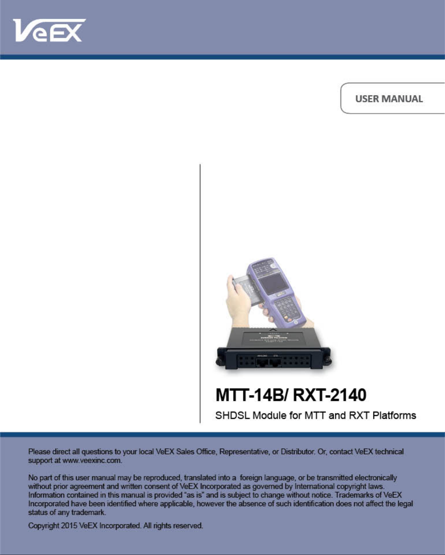
2.2.4.4 Pr
The PING
PROFILE (F1)
saving
configurations.
configuration, use this procedure:
1. From any PING
screen, select MODE and
press
PING Profile list screen is
displayed.
ofile
setup
screens feature
key. This allows
and
retrieving
To
PROFILE (F1)
various
save
a
configuration
and a
Figure
a
12:30:55
>LINK UP 4W STU-R<
PROFILE NAME :
MODE :LLC-BRG
ENCAPSULATION :LLC
VPI :8
VCI :35
IP ADDRESS :STATIC
LOCAL IP :003.044.055.066
DESTINATION IP:001.333.452.012
GATEWAY :005.180.190.200
EDIT
15 Profile
Configuration
Scr
SAVE
een
2. Use to
the
configuration screen shown
With the cursor on the PROFILE NAME line, give
3.
by pressing
4. Press INPUT
ENTER to select the character and the selected character
appears
•
If a mistake
incorrect character and then press:
DELETE (F2)
-
INSERT (F1)
-
OVER (F1)
-
5. When finished,
6. Press F4 to save the
configuration
Select
7.
the
remainder
ration
Invoking a Pr
1. From MODE,
screen use to
2. Press
Editing a
1. From MODE,
screen use to
Press
3.
played as in Figure 15.
4. Make any
first part of this
5. When finished,
select
a blank line and
press
in Figure
EDIT (F1)
15.
the Profile
EDIT (F1). A character
(F3)
to select the character grid and use
entry
screen
is
displayed.
to move the cursor to the desired character. Press
on the PROFILE NAME line.
is
made; press
STOP (F3), use to select the
Repeat
until
to delete the character.
to add a
character
left of the
selected
to replace a character with another character.
press
STOP (F3) to exit the
PROFILE
scr
een.
MODE,
sections.
choose
of the
When finished,
ofile
press
the
mode
screen
as in the
PROFILE (F1) and in the PING Profile
select a saved profile.
SELECT (F4)
Saved Pr
then F3 to start the PING
ofile
press
PROFILE (F1) and in the PING Profile
select a saved profile.
EDIT (F1) and the Profile
required changes
section.
press
F4 to save the
by using the
NAME and return to the PING
for the PING and
press
Configuration screen
character grid.
previous
PING
F4 to save the profile.
test.
procedures
altered Profile.
to
display
a name
finished.
character.
configur
configu
is
dis
in
list
list
the
e
-
-

VCC SCAN
ST: 08:29:57 ET: 00:10:00
# VPI VCI PTI CLP
MTT-14B e_Manual D07-00-083P RevA00
Page 26 of 101
2.2.5 Advanced Features
This menu screen contains the following optional features:
•
ATM
FEA
TURES
•
IP
FEA
TURES
2.2.5.1 ATM Features
This menu screen contains:
•
VCC SCAN
•
OAM CELL
•
OAM CELL STATISTICS
2.2.5.1.1 VCC Scan
This feature can scan up to 4
VCCs. ATM/IP traffic must be
transmitted from the
end while in VCC Scan. For
each detected VCC, the test set
displays the VPI (3 digits), VCI (5
digits), PTI (3 digits), and CLP (3
digits). A scanning bar is
displayed when scanning. When
full it resets and starts again.
This feature is used to verify what
location. Very often VCCs are directed toward the wrong
nation and they
assigned
VP/VC value may not be
The following is r
ST: Start Time indicates when the scan was
ET: Elapsed time indicates how long the scan has lasted.
#: Number of the VCC
VPI: Virtual Path Identifier
more VCIs. In UNI, the VPI is 8 bits. In NNI, the VPI is 12
rtual
VCI: Vi
the
physical
VCI
is 16
Channel
cell
bits.
UNI/NNI VPI and
GENERA
network
create
eported:
Identifier
transmission
VCI
values are given in the next two
TION
08:39:57
>LINK UP 2W STU-R<
PRINT
1 255 65535 111 1
SCANNING
Figure 16 VCC Scan Screen
PVC
is active at the
overflow of the
customer
known.
started.
address number containing
address number
within the switch fabric path.
line. Also,
which
STOP
customer
desti
the
one
or
bits.
facilitates
The
tables:
-

Use VPI VCI
Unassigned cell
00000000
00000000 00000000
Invalid
Any value
other
than
0
00000000 00000000
ing
Segment OAM F4 cell
Any value
00000000 00000011
4
cell
ment
functions
e
functions
e
5
00000000 00000111
Notes
any value from 01000 to 01111
any value from 10000 to 11111
MTT-14B e_Manual D07-00-083P RevA00
Page 27 of 101
Meta-signaling XXXXXXXX 00000000 00000001
General broadcast
Point-to-Point signal
XXXXXXXX 00000000 00000010
XXXXXXXX 00000000 00000101
-
End-to-end OAM F
VP resource
Reserved
manage
for future VP
Reserved for futur
Reserved for futur
functions
Any value 00000000 00000100
Any value 00000000 00000110
-
Any value 00000000 00000111
Any value
Any value
00000000 000SSSSS
00000000 000TTTTT
1
2
Segment OAM F5 cell Any value Any value other than
00000000 00000000,
00000000 00000011,
00000000 00000110,
00000000 00000111
End-to-end OAM F
cell
Any value Any value other than
00000000 00000000,
00000000 00000011,
00000000 00000100,
00000000 00000110,
1
2
Table 1 UNI VPI and VCI Values

Unassigned cell
00000000
00000000 00000000
Invalid
Any value
other
than
0
00000000 00000000
NNI signaling
Any value
00000000 00000101
4
cell
functions
functions
functions
00000000 00000000
5
0000000 00000110
VC
functions
00000000 00000000
Notes
any value from 01000 to 01111
any value from 10000 to 11111
MTT-14B e_Manual D07-00-083P RevA00
Page 28 of 101
Use VPI VCI
Segment OAM F4
End-to-end OAM F
VP
resource
ment
Reserved
Reserved
Reserved
Segment OAM F5
End-to-end OAM F
cell
VC
ment
Reserved for futur
1
2
for future VP
for future VP
for future VP
resource
cell Any value 00000000 00000011
Any value 00000000 00000100
manage
manage
Any value 00000000 00000110
-
Any value 00000000 00000111
Any value 00000000 000SSSSS
Any value 00000000 000TTTTT
cell Any value Any value other than
Any value Any value other than
00000000 00000000
Any value Any value other than
0000000 00000000,
e
Any value Any value other than
Table 2 NNI VPI and VCI Values
1
2
PTI:
Payload
Type Identifie
r is
a 3–bit field used
to indicat
e
whether the cell contains user information or Connection Associ-
ated Layer
be modified by any network
Management
information (F5 flow). The PTI bit
element
if
there is
congestion
may
in
the
system to notify other elements of the congestion. The values
table:
are given in the following

Bits 432
ATM user-to-user indication = 0
ATM user-to-user indication = 1
ATM user-to-user indication = 0
ATM user-to-user indication = 1
100
OAM F5 segment associated cell
101
OAM F5 end-to-end associated Cell
NNI - VC resource management cell
111
Reserved for future VC
functions.
after Rec. I.361, Sec. 2.2.4 and 2.3.3
MTT-14B e_Manual D07-00-083P RevA00
Page 29 of 101
PTI
Coding
Interpretation
000
001
010
011
110
User data cell, congestion not experienced.
User data cell, congestion not experienced.
User data cell, congestion experienced.
User data cell, congestion experienced.
UNI - Resource management cell
Table 3 PTI Decode Values
CLP: Cell Loss Priority is one bit that may be set by the
user
or the service provider to indicate lower priority cells (usually,
CLP=1); they are
subject
to
discard
before other
cells.
The following F-keys are
(F1):
PRINT
STORE (F3): Press
pr
essed.
is
S
TOP/STA
start.Once a scan
Press to print the scan results.
to
store
RT
(F4):
Press to stop scanning, press again to
is
started,
available.
the
scan results, available
a SCANNING
progress
after STOP
bar is
dis
-
played.

OAM CELL GENERATION
MTT-14B e_Manual D07-00-083P RevA00
Page 30 of 101
2.2.5.1.2 OAM Cell Generation
This screen contains configura
tion items for OAM cell generation.
Figure 17 OAM Cell Generation Screen
Configure
VPI
Options: 0–255
Enter the Virtual Path Identifier by using SHIFT and the
keypad.
VCI
Options: 0–65535
Enter the Virtual
ber
GFC
Options: 0000–1111
Enter a v
Flow Control
only for UNI interfaces. It is primarily used to ease
overload conditions (too many cells). As indicated in Figure 17,
contains
it
widely utilized, as the CLP
flow
CLP
Options: 0 or 1
Enter a v
keypad.
TYPE
Options:
(more, F1),
(more,
(more,
Choose the type of OAM cell to transmit. Refer to
2.2.5.1.3 for definitions of OAM cell
the items in the left column under OAM TRANSMIT:
See Section 2.2.5.1.1 for more information.
Channel
keypad.
See Section 2.2.5.1.1 for more information.
(binary only), default
alue using SHIFT and the numeric keypad. Generi
assists
in the control of the flow of traffic.
4 bits. It is an ATM layer function. In real-life it is
management job.
alue for Cell Loss Priority by using SHIFT and the numeric
See Section 2.2.5.1.1 for more information.
F4SGAIS (F1), F4SGRDI (F2), F4SG_LP (F3),
F4EERDI
F1), F5SGRDI
F1), F5EERDI
(more, F2),
(more,
(more,
-
12:03:43
>LINK UP 2W STU-R<
ST: ET:
VPI :8 # Tx : -
VCI :35 # Rx : GFC :0000 # LOST : CLP :0 ROUNDTRIP(ms)
TYPE :F5EE_LP CUR: -
#CELL :1 AVG:
TIMEOUT:2 sec MAX:
OAM TRANSMIT
STORE PRINT START
OAM RECEIVE
MIN: -
number
Identifier by using SHIFT and the
0000
short-term
(Cell
Loss Priority indicator) does the
F4EEAIS
F4EE_LP
F2), F5SG_LP
F2), F5EE_LP
(more, F3), F5SGAIS
(more,
F3),
F5EEAIS
(more, F3)
Sectio
types.
-
-
num-
Used
not
n
c

MTT-14B e_Manual D07-00-083P RevA00
Page 31 of 101
#CELL
Options: 1–9999
Enter the
the
TIMEOUT
number
number keypad.
Options: 1–10 seconds
Enter a v
alue in seconds
This is only
is received after the timeout has expired, the cells are declared
lost. This field is set to N/A for AIS and RDI (F4 or F5) since
response is
The
items in the right column under OAM
of the OAM ATM PING.
# Tx: Number of OAM cells
Note: The following items
F5)
cells are received.
or
# Rx: Number of OAM
# LOST: Number of
ered lost due to the
The following items are under
CUR: C
urrent cell roundtrip in milliseconds.
AVG: Average cell roundtrip in milliseconds.
MAX: Maximum cell roundtrip in milliseconds.
MIN: Minimum cell roundtrip in milliseconds.
The following F-keys are
STORE
PRINT
(F2):
(F3):
of OAM cells to
transmit
by using SHIFT
used
for
expected.
by using SHIFT and the
loopback
(F4 or F5) cells.
number keypad
If
no r
RECEIVE are
transmitted.
will
loopback
transmitted
timeout.
available:
display N/A,
OAM
ROUNDTRIP
cells r
cells not
unless loopback
eceived.
received;
(ms).
Press to store the OAM ATM PING results.
Press to print the OAM ATM PING results.
and
esponse
no
the results
(F4
consid
.
-

OAM CELL STATISTICS
ST: 12:05:43 ET: 00:10:00
TIME VPI VCI OAM TOTAL
12:14:55 008 00032 F4SG_LP 10
MTT-14B e_Manual D07-00-083P RevA00
Page 32 of 101
2.2.5.1.3 OAM Cell Statistics
Inter
net
B-RAS can
send OAM
cells.
B-RAS
Router
ATM
can send OAM
This feature automatically responds to any ATM OAM requests.
screen does
The
piled as long as the link is up.
in
ADVANCED FEATURES
Each time that an OAM request
is received and answered, the
counters in the screen to the
right get updated. The test set
will reply to F4/F5 (segment/
path) OAM loop commands.
also counts received AIS and
RDI F4/F5 OAM cells.
Testset replies to OAM cells, if required (i.e. loop)
Figure 18 OAM Connection
not
need
Figure 19 OAM Cell Statistics Screen
The following is r
ST: Indicates when the
(F3)
was last pressed.
ET: Elapsed time since the measurement was started or when
CLEAR (F3)
# OF OAM REQUEST:
received during the capture time.
PAGE:
TIME:
VPI/VCI
Indicates
Indicates
pair
eported:
measurement
was last pressed.
the
current page
the
capture
switches
cells.
DSLAM
can send
OAM cells.
ATM
to be
> IP
Statistics
DSLAM
displayed
for
are not
FEATURES
12:15:43
>LINK UP 2W STU-R<
# OF OAM REQUEST:0010
PAGE: 1
It
PAGE-UP PAGE-DN CLEAR more
STORE PRINT
was started or when CLEAR
Indicates the total
number.
time of the first
STU
results
recorded while
menu.
more
number
request
for the OAM
STU-R
to be
com
of OAM’s
-

MTT-14B e_Manual D07-00-083P RevA00
Page 33 of 101
VPI:
Indicates
Indicates
VCI:
OAM: The following Operations Administration Messages:
F4SGAIS: AIS F4 (path) on the segment
F4SGRDI: RDI F4 (path) on the segment
F4SG_LP: loopback request
F5SGAIS: AIS F5
F5SGRDI: RDI F5
F5SG_LP: loopback request
F4EEAIS: AIS F4 (path)
F4EERDI: RDI F4 (path)
F4EE_LP:
F5EEAIS: AIS F5
F5EERDI: RDI F5
F5EE_LP:
TOTAL:
ceived.
The following F-keys are
PAGE-UP
screens.
CLEAR
STORE (more,
PRINT (
the Virtual Path Identifier;
the Virtual
Channel
000–999
Identifier;
F4 (path) on the
(channel)
(channel)
on the segment
on the segment
F5 (channel) on the
end-to-end
end-to-end
loopback request
(channel)
(channel)
end-to-end
end-to-end
loopback request
Indicates
the total
number
available:
(F1)
and PAGE DN
(F3):
Press to clear the counters and restart the
F1):
Press to store the results.
more,
F2):
Press to print the results.
(F2):
F4 (path)
end-to-end
F5 (channel)
of a
specific
Press to scroll through the
00000–65535
segment
segment
end-to-end
OAM cell re-
test.

MTT-14B e_Manual D07-00-083P RevA00
Page 34 of 101
2.2.5.2 IP Features
These optional features provide advanced Internet
troubleshooting
through detailed connection status, PING statis-
tics, and trace route. The menu screen contains the
•
CONFIGURATION
•
IP STATUS
•
PING TEST
•
TRACE
•
ECHO
ROUTE
RESPONSE
connectivity
following:
2.2.5.2.1 Configuration
After
turning
from the
the IP
up the link, select IP FEATURES > CONFIGURATIO
main menu. This screen contains configuration items fo
connection.
Enter the
proper protocol used
by the
cir
N
r
cuit,
as well as the necessary IP addresses.
CONNECT/DISC appears at either F3 or F4 depending on the
pro
setting selected. Press CONNECT to start the connection
cedure to the ISP. Press DISC to release the connection. Once
CONNECT
is pressed; the connection will stay UP, if successful,
or DOWN if unsuccessful. In either case, press DISC to change
any of the
configuration
items.
MODE
Options: PROFILE
CLIPoA (more,
Select the protocol mode for the PING
•
•
• LLC-RTE refe
s
• CLIPoA
RFC2225.
•
•
Note: The
selected MODE as seen in Figure 20:
(F1),
LLC-BRG
F2),
PPPoE (more,
PROFILE allows storing and retrieving of IP
see the
subsection
entitled Profile
(F2),
LLC-RTE (more, F1),
F1),
PPPoA (more, F2)
test.
Setup
.
configurations,
LLC-BRG refers to LLC-Bridge protocol. This follows RFC
1483
(DHCP)
tatic
IP
bridge encapsulation. It supports both static
IP management.
rs to LLC-Routed protocol. It
addr
essing.
and dynamic
supports only
refers to Classical IP over ATM according to
It only supports Static IP
essing.
addr
PPPoE refers to PPP over Ethernet, according to standar
RFC 2516 PPP over
and dynamic IP
Ethernet. PPPoE supports
addr
essing.
both
PPPoA refers to PPP over ATM, according to standard RFC
2364, PPP
namic IP
actual configuration settings displayed
over AAL5. PPPoA
addr
essing.
supports
both static and dy-
depend
on the
d
static

MTT-14B e_Manual D07-00-083P RevA00
Page 35 of 101
11:50:45
>SHOWTIME <
> 4W STU-R<
MODE :LLC-BRG
ENCAPSULATION :AUTO
IP TYPE :STATIC
VPI :8
VCI :35
LOCAL IP :102.168.102.101
GATEWAY :255.255.255.0
DNS SERVER :MANUAL
DNS SERVER IP :206.13 .28 .12
STATIC
11:50:45
>SHOWTIME <
> 4W STU-R<
MODE :PPPoE
ENCAPSULATION :LLC
IP TYPE :DYNAMIC
AUTHENTICATION:AUTO
VPI :8
VCI :35
DNS SERVER :MANUAL
DNS SERVER IP :206.13 .28 .12
USER ID :
PASSWORD :
STATIC
Notes
•
•
Common F-keys and Procedures
The
common navigation
<-
->
To enter
Configure
CONFIGURATION
DHCP CONNECT STATIC DHCP CONNECT
11:50:45
>SHOWTIME
> 4W STU-R<
MODE :LLC-RTE
ENCAPSULATION :AUTO
VPI
VCI
LOCAL IP
DNS SERVER
DNS SERVER IP :206.13 .28
CONFIGURATION
*****
*****
DYNAMIC
Figure
PPPoE STATIC
CONFIGURATION
LLC
VC MUX AUTO CONNECT
CONNECT
20 IP
is shown,
11:50:45
>SHOWTIME <
> 4W STU-R<
MODE :LLC-BRG
ENCAPSULATION :AUTO
IP TYPE :DHCP
VPI :8
VCI :35
DNS SERVER :AUTO
:8
:35
:003.044.055.066
:MANUAL
11:50:45
>SHOWTIME <
> 4W STU-R<
MODE :CLIPoA
ENCAPSULATION :LLC
VPI :8
VCI :35
LOCAL IP :003.044.055.066
DNS SERVER :MANUAL
DNS SERVER IP :207.181.199.177
NONE MANUAL CONNECT
Configuration
PPPoA STATIC
CONFIGURATION
<
.12
CONFIGURATION
Scr
eens
has the same
features, except MODE is PPPoA
PPPoE-DYNAMIC
is shown,
PPPoA DYNAMIC
has the same
setup features, except MODE is PPPoA.
number
(F2):
(F3):
entry fields in the IP
F-keys. They are:
Configuration
Moves the inse rtion point one place to the
Moves the inse rtion point one place to the
numbers, press
the
following:
SHIFT and use the numeric
screens have
left.
right.
setup
keypad.

MTT-14B e_Manual D07-00-083P RevA00
Page 36 of 101
ENCAPSULATION
(F1),
Options: LLC
Choose
the
Type 5 over
•
LLC: Logical Link Control
VC MUX
encapsulation method
ATM
as
described
used when multiple protocols are encapsulated over a single
ATM virtual
• VC MUX: (not
connection.
in CLIPoA or PPPoE modes) Used when o
protocol is carried over a single ATM virtual
•
AUTO: (not
in
CLIPoA
cally detect the encapsulation.
IP TYPE (not in LLC-RTE or CLIPoA)
Options:
NAMIC
• STATIC: The IP
•
STATIC (F1),
(F2,
only in PPP mode)
address is statically assigned to the
the known IP
address
DHCP: Dynamic Host
for
devices
IP
address)
dress
an
address
ADDRESS,
to obtain
dynamically from the
is not fixed to the device;
from a network DHCP
the test set sends a DHCP request to the server;
the server responds and provides an IP address. Note
upon selecting DHCP, the LOCAL IP setting disappears.
•
DYNAMIC:
to obtain
Dynamic management provides a way for devices
protocol configuration
dynamically from the
is not fixed to the device;
address
DRESS,
from the network
the test set sends a request to the server; the server
responds and provides an IP address to use. Note that
selecting DYNAMIC the LOCAL IP setting disappears.
AUTHENTICATION (not in LLC-BRG, LLC-RTE, CLIPoA)
Options: PAP (F1), CHAP (F2), AUTO (more F1), NONE (more,
F2, only in PPPoA MODE)
ensures
This
with the
•
PAP:
that only a valid
network.
Password Authentication Protocol as in
is the simplest method for authentication. It involves a
way
handshake
another
to
back an
authentication-acknowledge message
where one peer
peer network
ing or rejecting the user name and password. Note that when
selected, a password
(F2),
AUTO (F3)
for carrying traffic over AAL
in RFC
based
on
2684.
IEEE
standard
802.2. It
connection.
or
PPPoE modes) Use
DHCP
(F2,
only in LLC-BRG
this to automati
MODE), DY
user
in the LOCAL IP
field.
Configuration Protocol provides a way
protocol configuration
network.
instead
server.
parameters
network.
In this
instead,
server.
the terminal
When
parameters (local
In this, the IP ad-
the
device r
When
selected
(local IP
case,
the IP
requests an
selected
for IP AD-
address)
device establishes a connection
RFC
1334. This
sends
element.
a user
The receiving peer
name
either
and ID
will
need
to be
enter
ed.
nly one
-
. Enter
equests
for
IP
that
addr
ess
upon
two-
and ID
sends
accept
is
-
-

MTT-14B e_Manual D07-00-083P RevA00
Page 37 of 101
•
CHAP: Challenge Handshake Authentication Protocol as in RFC
1994. It
involves a
three-way handshake. In this,
the
sends a challenge containing its user name. The server sends
response with
a
a specific identifier
expected
for this transac-
tion. The test set then accepts or rejects this response. Once
done,
the
handshake is complete and
•
AUTO: Use
authentication
the
•
NONE: Available for PPPoA, no
this recommended setting to automatically
type
requested
data
may be sent.
by the ISP.
authentication
is r
equir
VPI
Range: 1 to 255 (default 8)
Along with the VCI, this identifies the next
destination
of a
as it moves through a series of ATM switches to its destination.
It is typically
assigned
by the
service pr
ovider.
VCI
Range: 1 to 65535 (default is 35)
Along with the VPI, this identifies the next
destination
of a
as it moves through a series of ATM switches to its destination.
It is typically
assigned
by the
service pr
ovider.
LOCAL IP (not in DHCP or DYNAMIC IP)
Specify the IP
GATEWAY
address
(LLC-BRG only)
of the circuit to be
tested.
Specify the gateway address. A gateway is a device that
nects dissimilar networks
and
passes information
between them
In TCP/IP, the default gateway address is the address where the
Internet
unless
Protocol sends packets destined
a different route is
configur
ed.
for
remote networks,
DNS SERVER
Options: NONE (F1), MANUAL (F2), AUTO, only for LLC-BRG
DHCP and PPPoE, PPPoA modes (F3)
The Domain Name System Server translates IP addresses
domain names and vice versa. DNS allows you to reference
domain names instead of their actual numerical IP address. I.e.,
t
www.VeEXtelecom.com
•
NONE:
and web
•
MANUAL: Manually enter the IP address of the DNS server.
No domain
access tests
ranslates to 216.102.182.
name server
will
, is used.
only use an IP
The PING
addr
ess.
trace route,
Note that at the time of connection the test set will verify the
addr
ess.
validity of the DNS server IP
•
AUTO: This will
automatically
obtain the DNS server IP ad-
dress upon connection to the ISP.
test se
detect
ed.
cell
cell
con
into
t
-
.

MTT-14B e_Manual D07-00-083P RevA00
Page 38 of 101
USER ID (not in LLC-BRG, LLC-RTE, or CLIPoA modes)
(PAP
and
For authentication
ceiving an IP
address
from the ISP. See the following
CHAP),
entitled Entering a User ID/Password.
PASSWORD (not in LLC-BRG, LLC-RTE, or CLIPoA
For
authentication (PAP and CHAP), enter a password prior
receiving an IP address from the ISP. See the following
tion entitled Entering a User ID/Password.
When finished configuring
connect.
F3 to
Entering a User
ID/Passwor
1. Place the cursor on
2. Press
3. Press INPUT
EDIT (F1)
(F3)
the IP CONFIGURATION
d
USER
ID.
and the character entry screen is displayed.
and a cursor appears in the
4. Use to move the cursor to the desired character.
ENTER
Press
pear in the
to select that character. The character will ap
USER
ID line.
5. Continue selecting characters until done. Press
exit the
character
grid.
If a mistake
and use to select the incorrect character.
•
Press
•
Press
DELETE (F2)
INSERT (F1)
to delete the character.
to add a character to the left of a se-
lected character.
•
Press
OVER (F1)
6. At HIDE USER ID,
pressing
YES
in Figure 20 the
to replace the selected character.
choose whether
(F1)
or NO
(F2).
USER
ID and
7. Press SAVE (F4) to save the ID and return to the Setup
screen.
8. Select
PASSWORD
and follow the previous procedure.
enter a user ID prior to re-
subsection
modes)
screen, press
grid.
STOP (F3)
is
made; press
to hide the ID
In the
bottom
PASSWORD
left
screen shown
are hidden.
to
subsec
-
-
to
STOP (F3)
code by

MTT-14B e_Manual D07-00-083P RevA00
Page 39 of 101
Profile
11:50:45
>LINK UP <
PROFILE NAME :
MODE :LLC-BRG
ENCAPSULATION :AUTO
IP TYPE :DHCP
VPI :8
VCI :35
DNS SERVER :NONE
Setup
11:50:45
>LINK UP <
PROFILE NAME :
MODE :LLC-BRG
ENCAPSULATION :AUTO
IP TYPE :STATIC
VPI :8
VCI :35
LOCAL IP :0 .0 .0 .0
GATEWAY :0 .0 .0 .0
DNS SERVER :NONE
EDIT
SAVE EDIT SAVE
Figure
IP CONFIGURATION
for saving and retrieving
Creating and Saving a Pr
1. From the IP
In the PROFILE screen, select a blank line
2.
the last configured IP
3. In either screen, when the cursor is on
the profile a
In the displayed character entry screen, press INPUT
4.
cursor
appears
21 Profile
features
Configuration
a PROFILE (F1) F-key that
complete
ofile
CONFIGURATION,
CONFIGURATION
name
by
pressing
in the
character
Scr
eens
IP
configurations:
select MODE and press F1.
and press EDIT (F1) and
EDIT
screen
PROFILE
(F1).
is
displayed.
NAME give
(F3) and
grid. Use to move
that cursor to a desired character. When it is selected, press
ENTER
If a mistake
incorrect character. Press one of the
•
•
•
When finished,
5.
Press
Figure 21.
configuration
6. When finished,
Editing a
1. From the IP
2. In the PROFILE listing
3 In the
when finished,
Invoking a Pr
1. From the IP
2. In the PROFILE listing
3. Press F3 to connect and start the
and the character will appear after
is
DELETE (F2)
INSERT (F1)
OVER (F1)
F4 to
to replace the selected character.
save
Configure
sections.
Saved Pr
made, press
to delete the character.
to insert a character.
press
F3 to exit the
the
name
the rest as
press
F4 to save the profile.
ofile
F3 and use to select the
and return to one of the
configuration screen, press F1.
screen, select
configuration screen,
press
F4 to save the
ofile
make any
configuration screen, press F1.
screen, select
PROFILE
following:
character grid.
discussed
in the previous
a profile and
required
changes.
a profile and
pr
ocedure.
NAME.
screens
press F1.
changes and
press F4.
allows
a
in

MTT-14B e_Manual D07-00-083P RevA00
Page 40 of 101
2.2.5.2.2 IP Status
These screens are displayed after pressing CONNECT in IP
CONFIGURATION (except
LLC-RTE
and CLIPoA).
They
report im-
portant information on the status of the connection to the ISP.
•
LLC-RTE and CLIPoA: ‘UP’ is
•
LLC-BRG: Information
about
the DHCP
• PPPoE
and PPPoA STATIC or
the PPP session is r
LLC-BRG/DHCP IP Status
11:50:45
>LINK UP UP<
ST:11:20:40 ET:000:30:05
STATUS
IP
about
session
eported.
DHCP:PASS
LOCAL IP :207.181.199.105
DHCP SERVER :207.181.199.100
DNS SERVER :206.13.28.12
GATEWAY :207.181.199.178
SUBNET MASK :255.255.255.000
LEASE TIME :00:60:00
displayed
the ARP
in
dynamic mode
DYNAMIC:
when the link is
request
is r
Information
11:50:45
>LINK UP UP<
ST:11:20:40 ET:000:30:05
PAGE:1
DHCP disc ---->
DHCP req ---->
ARP req ---->
ATU-R ISP
<---- DHCP
<---- DHCP
<---- ARP
in STATIC
eported.
about
offer
ack
reply
up.
or
DETAIL
Figure 22 DHCP IP Scr
In this
sage
address. During this process, the following is r
ST: Start time indicates when
ET: Elapsed time since
The status of the connection to the ISP is displayed on the
side of the
be DHCP DOWN,
der the IP STATUS line in the left
DHCP:
DHCP: PASS: A successful
DHCP: FAIL:
one of t
•
• DHCP DISCOVERY FAILED: There is no response
•
If DHCP: PASS is displayed, the following is r
•
configuration,
to start DHCP
screens.
the test set
negotiation
It can be DHCP UP,
if
it has failed. The
in progress: Connection is not yet
Connection
he following messages:
LINK
DOWN: Link is
discovery message
an incorrect VP/VC or an incorrect
DHCP REQUEST FAILED: A DHCP
message
LOCAL
has
been
IP: STU-R IP
PAGE-UP PAGE-DN SUMMARY
eens
sends
a DHCP
discovery
with the ISP and obtain an
eported:
CONNECT
CONNECT
screen
was pressed.
was pressed.
if
it has
status
is also
of Figure 22. It can
passed,
completed.
connection.
was not
closed.
sent by the STU-R. The
sent by the DHCP
successful
protocol.
NACK or
server.
as
reason
DHCP
eported:
address assigned
by the DHCP
mes
IP
right
or it
can
displayed un-
be:
indicated by
to the DHCP
could
be
DECLINE
server.
-

PAGE:1
ATU-R ISP
ARP req
---->
MTT-14B e_Manual D07-00-083P RevA00
Page 41 of 101
•
DHCP SERVER: DHCP server IP
then the ISP did not return a DNS server IP address or it was
invalid.
•
GATEWAY:
•
SUBNET MASK:
•
LEASE TIME:
Gateway IP
addr
Netmask.
Duration shown in HH:MM:SS of the
allocation.
The screen contains this F-Key:
(F4):
DETAIL
reports
22. It
between
vides the
the STU-R and the ISP. It
PAGE-UP
Press to display the right screen shown in Figure
the
details
of the
the STU-R and the DHCP
protocol decode
of the
contains
(F1)
and PAGE-DN
screens.
(F4):
SUMMARY
LLC-BRG Static IP Status
11:50:45
>LINK UP UP<
ST:11:20:40 ET:000:30:05
IP
Press to return to the IP
STATUS
ARP:PASS
LOCAL IP :192.168.102.106
GATEWAY :207.181.199.178
DNS SERVER :206. 13. 28. 12
DETAIL
Figure 23 ARP IP Scr
After pressing
CONNECT
in
IP CONFIGURATION,
send an ARP (Address Resolution Protocol) request to the ISP
in order to verify the IP
ST:
ET:
Indicates
Elapsed
when the CONNECT key was pressed.
time since the CONNECT key was pressed.
configuration.
The status of the connection to the ISP is displayed on the
side of the
be
‘ARP DOWN’,
screens.
if it has failed.
It can be ‘ARP UP’,
the IP STATUS line in the left
ARP: in progress: Connection is not yet
ARP: PASS: A successful
ARP:
FAIL:
Connection
connection.
was not
the following messages:
address. If this reports FAIL,
ess.
IP
addr
handshake messages exchanged
server.
The
screen
also pro
messages exchanged between
the following
(F2):
Page through any
11:50:45
>LINK UP UP<
ST:11:20:40 ET:000:30:05
<---- ARP
PAGE-UP PAGE-DN SUMMARY
eens
F-keys:
STATUS
additional
screen.
rep
the test set will
The following is r
eported:
right
if
it has
passed,
The
status is also displayed under
screen
of Figure 23. It can
competed.
or it
be:
successful; indicated
by one of
ess
-
can

MTT-14B e_Manual D07-00-083P RevA00
Page 42 of 101
•
LINK
DOWN: Link is
•
WRONG CONFIGURATION: Wrong VP/VC, protocol, local
address or gateway IP
If ARP: PASS, the following is r
•
LOCAL
•
GATEWAY:
•
DHCP
IP: STU-R IP
Gateway IP
SERVER:
closed.
address assigned
addr
addr
ess.
eported:
ess.
by the DHCP
DHCP server IP address. If reports
server.
FAIL,
the
ISP did not return a DNS server IP address or it was invalid.
The screen contains this F-Key:
(F4):
DETAIL
reports
23. It
between
decode
ISP. It
contains
PAGE-UP
Press to display the right screen shown in Figure
the
details
the STU-R and the
of the
messages exchanged between
the following
(F1)
and PAGE-DN
of the
handshake messages exchanged
gateway. It also provides
the STU-R and th
F-keys:
(F2):
Page through any
the protocol
e
additional
screens.
SUMMARY
(F4):
Press to return to the IP
STATUS
screen.
PPP Static or Dynamic IP Status
11:50:45
>LINK UP UP<
ST:11:20:40 ET:000:30:05
IP STATUS
ROUTER:PASS
PPP :PASS
LOCAL IP :207.181.199.105
GATEWAY :207.181.199.178
DNS SERVER :206. 13. 28. 12
SUBNET MASK :255.255.255.000
AUTHENTICATION:PAP
DETAIL
11:50:45
>LINK UP UP<
ST:11:20:40 ET:000:30:05
PAGE:1
PAP req ---->
IPCP cfg req ---->
IPCP cfg req ---->
PAGE-UP PAGE-DN SUMMARY
ATU-R ISP
<---- PAP ack
<---- IPCP cfg
<---- IPCP cfg
nack
ack
Figure 24 PPP IP Scr
eens
After
pressing CONNECT
start the
PPP
negotiation with the
ST: Indicates when
ET: Elapsed time since
The status of the connection to the ISP is displayed on the
side of the
be ‘PPP DOWN’,
screens.
if it has failed.
the IP STATUS line in the left
ROUTER:
ROUTER:
parameters
in progress: Connection is not yet opened.
PASS: The ISP has responded and the
have
been successfully
in IP
CONFIGURATION,
ISP. The
CONNECT
CONNECT
was pressed.
was pressed.
It can be ‘PPP UP’,
The
status is also displayed under
screen
of Figure 24. It can
negotiated.
the test set will
following is reported:
if
it has
passed,
or it
be:
connection
right
can

MTT-14B e_Manual D07-00-083P RevA00
Page 43 of 101
ROUTER: FAIL: The ISP has not responded or the negotiation
of the connection parameters has failed.
PPP: in progress: Connection is not yet opened.
PPP:
PASS: The authentication and IP parameters of the
nection
have
been successfully negotiated
and the
is UP. If successful, the following is displayed:
•
LOCAL IP: STU-R IP
•
GATEWAY:
•
SUBNET MASK:
•
DHCP SERVER: DHCP
Gateway IP
addr
ess.
addr
ess.
Netmask.
server IP address. If
FAIL,
not return a DNS server IP address, or it was invalid.
•
AUTHENTICATION:
Authentication mode
PAP
, CHAP or NONE
(only in PPPoA).
PPP: FAIL: Indicates that the authentication or the
connection
of the
the
connection
•
LINK
DOWN: Link is
•
PPP-RESPONSE TIMEOUT (
to the
messages
an incorrect VP/VC or an incorrect
•
PPPoE DISCOVERY FAILED (
to the
discovery messages
could be an
•
WRONG
CHAP, or
haven’t
is down. A
been successfully negotiated
messages
closed.
sent by the STU-R. The
incorrect
VP/VC or an
AUTHENTICATION:
NONE-PPPoA only) is
can be
PPPoA o
nly): There is no response
protocol.
PPPoE o
nly): There is no response
sent by the STU-R. The r
incorrect
The authentication mode (PAP
not the one
IP
parameters
displayed:
reasons
protocol.
expected
ISP.
•
WRONG USER ID or PASSWORD: The STU-R has not
authorized
•
WRONG CONFIGURATION: The negotiation of the IP pa-
rameters
an
incorrect
tions.
by the ISP.
of the
connection
local IP
address
has failed. The
for
PPPoE
or PPPoA
reason
The screen contains this F-Key:
DETAIL
It
tween the
decode
ISP.
PPPoE discovery stage.
PAGE-UP
(F4): Press
reports
the details
STU-R
of the
Note that in
to display the right screen shown in
of the
handshake messages exchanged be
and the
PPP server.
messages exchanged between
a PPPoA
(F1)
and PAGE-DN
handshake,
It
contains
(F2):
the following
Page through any
It also provides the protocol
the STU-R and th
the
messages exclude th
F-keys:
screens.
SUMMARY
(F4):
Press to return to the IP
STATUS
screen.
con
connection
the
ISP
did
and
that
could
be
easons
by the
been
could
be
configura
Figure
24.
additional
-
,
-
-
e
e

MTT-14B e_Manual D07-00-083P RevA00
Page 44 of 101
2.2.5.2.3 PING Test
Before running this test, the
connection must be UP as
indicated at the top right of the
screen.
This screen is the same for all
the encapsulation types. Press
F4 after configuration to
start
the test. Press again to stop the
test.
The following is displayed:
ST:
Indicates
ET:
Elapsed
LOCAL IP: Displays the LOCAL IP entered in the CONFIGURA-
TION
screen,
dynamically assigned address if DHCP or DYNAMIC IP TYPE
been selected
has
Configure
DESTINATION IP
Options:
Enter the Destination IP
•
GATEWAY: Use to automatically PING the Gatewa
not available in LLC-RTE and CLIPoA
•
IP ADDR: Use to enter a destination address. Use SHIFT
and
a saved IP address from the
•
URL:
domain name
(F1)
TION IP
To sa
ve a URL or IP address, use this procedure:
1.
Press
line and press
2. In the
pressing URL
this
A. Press to select
numeric key
B. When finished,
3. In the PING
4. Press F3 to select the character grid with a cursor.
5. Use to move the cursor to the desired character.
when the START key was pressed.
time since the START key was pressed.
if
static IP TYPE has
in the CONFIGURATION
the following for PING
GATEWAY (F1),
URL/IP
addr
number keypad
Uniform
Resource
if
along with , or press F3 and select
a DNS server is
for a character entry
list.
F2 and the in the
EDIT
(F1).
character
screen
(F1)
is
replaced
entry
or IP ADDR
DESTINATION
pad,
<-- (F2) and --> (F3) to
press
configuration screen, press
11:50:45
>LINK UP UP<
ST:--:--:-- ET:---:--:--
LOCAL IP:207.181.199.106
DESTINATION IP:207.181.199.178
#PINGS: 0 PING LEN: 54
PING/SEC: 1
PING: -
Sent :0 Round Trip (ms)
Recv’d :0 Crnt :0
Unreach:0 Avg :0
Missing:0 Max/Min:0/0
CONTINU
Figure 25 PING Test Screen
testing:
ADDR (F2),
ess.
list.
Locator is used to
screen
DESTINATION
screen select
by a numeric entry
F4 to
save.
been selected.
modes.
available.
or
LIST (F2)
IP list
the type of
(F2).
If IP ADDR is selected,
IP and use SHIFT, the
PING TEST
START
It
displays
scr
een.
LIST (F3)
y. IP address
enter a
To enter,
destination
press
for the DESTINA-
select a blank
address by
scr
een.
enter
.
to select URL.
the
URL

MTT-14B e_Manual D07-00-083P RevA00
Page 45 of 101
Press
ENTER
pear in the URL line. Repeat this until done then press STOP
(F3)
to exit the character
•
If a mistake
the incorrect character.
- Press
- Press INSERT
selected character.
- Press
6.
Press
F4 to save and return to PING
#PINGS
Options: 1-999999; default is 10.
Select
the
number
pad and to enter a
PING LEN
Options: 64-1500 bytes;
Select
and to enter a value.
the PING length to
PING/SEC
Options: 1-10; default is 1.
Select
the
number
the
number keypad
When re
ing is r
ady,
eported:
PING: result will indicate:
PING: –: The test hasn’t
PING: IN
PING: PASS: At least 1
PING: FAIL: An
PING: NO DNS SERVER: The DNS server is
PING: DNS LOO KUP FAILED: The IP
associated with the host name.
The
bottom
Sent: Number of PINGS sent to the
Recv’d: Number of
Unreach: Number of
Missing: Number of
Round
(Current),
is r
Trip:
Avg
eported.
to select that character. The character will ap
grid.
is
made, press
DELETE (F2)
(F1)
OVER (F1)
STOP (F3) and use to select
to delete the character.
to add a character to the left of the
to replace the selected character.
configuration.
of PINGS to
of PINGS to
send. Use SHIFT, the
number,
default is
or
send.
Use SHIFT, the
send
press
64.
per
F1 for
second
continuous.
number keypad
from.
and to enter a value.
press
F4 to begin.
Press
again to
stop.
been started.
PROGRESS: The test is in process.
echo response
echo response
has not
has
been r
been r
unavailable.
address
of the
screen reports
Measure
(Average)
correct echo responses r
echo responses
echo responses missing.
of the round trip delay in milli seconds.Crn
and Max/Min (Maximum and Minimum)
the
statistics
network.
with an
of the
eceived.
unreach flag.
number key-
Use SHIFT,
The follow
eceived.
eceived.
could not
test:
-
-
be
t

PAGE:1
Hop Type msec Host Address
2 TTL 124 129.250.2.246
3 TTL 97 129.250.5.253
MTT-14B e_Manual D07-00-083P RevA00
Page 46 of 101
2.2.5.2.4 Trace Route
Before running the test, UP
be displayed as indicated at the
top right of the screen.
Use this screen to send PING
messages to a destination
address and trace the messages
thr
across the routers
ough
which they travel. The result
screen is the same for all
types.
encapsulation
After entering a destination IP address (see Section 2.2.5.2.3),
press F4 to start. Press again to stop it, resetting ET to zero.
Scroll through the results using .
displayed page number. Configure
LOCAL
CONFIGURATION. If DHCP/DYNAMIC,
DESTINATION IP
Options:
•
•
•
The following is reported after pressing F4:
ST: Indicates when
ET: Elapsed time since
Hop: Displays up to 32 router
Type:
msec: Duration of a hop (roundtrip).
Host Address: Responding router’s IP
Host Name: Press
(if
Use
(F2) to display the host
IP: If
STATIC
GATEWAY (F1),
IP
TYPE,
URL/IP
GATEWAY: Use to automatically PING the Gatewa
not available in LLC-RTE and CLIPoA
IP
ADDR:
Use to enter a destination address. Use
numeric keypad and , or
URL:
Uniform
domain name
(F1)
for a character entry
Resource
if
a DNS server is
Locator is used to
TION IP list. To save, see Section 2.2.5.2.3.
START
was pressed.
START
Describes
the type of hop. It can be the following
ECHO: The destination IP has responded.
MISS: A router or destination IP has not responded.
TTL: Time To Live field of the PING
remented, and successfully passed a router.
MORE (F2)
DNS server is
enabled).
to select a hop and press
name
11:50:45
must
>LINK UP UP<
ST:11:50:00 ET:00:00:45
LOCAL IP:38.168.47.121
DESTINATION IP:209.130. 6.142
1 TTL 98 123.250.2.209
4 TTL 115
5 TTL 162
6 TTL 143
PING MORE
TRACE ROUTE
129.250.4.14
129.250.28.52
129.250.4.52
Figure 26 Trace Route Screen
PAGE
displays the currently
the
enter
LOCAL
ADDR (F2),
following:
this is network
IP in IP
LIST (F3)
FEATURES
assigned.
y. IP address
modes.
SHIFT,
press
F3 and select from the list.
screen
available.
or
LIST (F2)
enter a
To enter,
destination
press
for the DESTINA-
was pressed
hops.
types:
message
addr
ess.
has
been
or use to see the Host Name
F1
to
PING
it, or press MORE
(if
available).
STOP
the
URL
dec
>
-

PAGE: 1
TIME PING FROM TOTAL
MTT-14B e_Manual D07-00-083P RevA00
Page 47 of 101
2.2.5.2.5 Echo Response
Before running the test, UP
must
be displayed as indicated at the
top right of the screen.
back
This screen runs in the
-
ground, updating continuously.
(F1)
Use PAGE-UP
(F2)
DN
to scroll any available
and PAGE-
screens.
The following is r
eported:
Figure 27 Echo Response Screen
11:50:45
>LINK UP UP<
ST:11:50:00 ET:00:00:45
LOCAL IP:38.168.47.121
# OF ECHOED IPS: 1
11:50:40 206.181.199.105 10
PAGE-UP PAGE-DN
ECHO
RESPONSE
ST: Indicates when
CONFIGURATION.
Elapsed Time
ET:
> CONFIGURATION.
LOCAL
IP: If
STATIC
CONFIGURATION. If DHCP/DYNAMIC,
# OF ECHOED IPS:
PINGs to the module.
PAGE: Current
TIME: Timestamp of the last
addr
ess.
IP
PING FROM: IP address that sent the PING.
TOTAL: Number of PINGs
dress.
CONNECT
since
Number
page
was pressed in IP
CONNECT
IP
TYPE, enter LOCAL
was pressed in
of different IP
number.
PING
received from the associated
received
FEATURES
IP
IP in IP
FEATURES
this is network
addresses which sent
from the
associated
>
FEATURES
>
assigned.
IP ad-
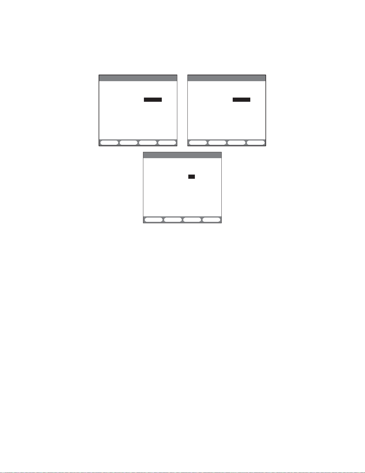
MTT-14B e_Manual D07-00-083P RevA00
Page 48 of 101
08:39:57
>LINK DN- Idle STU-C
TEST
CONFIGURATION
MODE : STUC-E1
TX SOURCE : TESTPAT
FRAMING : PCM-30
CRC-4 : YES
TEST RATE : 2.048M
RX PORT : TERM
TX CLOCK : INTERN
E1<
2.3 STUC E1, STUR E1, and E1
Configuration
08:39:57
>LINK DN- Idle STU-R
TEST
MODE : STUR-E1
TX SOURCE : TESTPAT
FRAMING : PCM-30
CRC-4 : YES
TEST RATE : 2.048M
RX PORT : TERM
TX CLOCK : INTERN
STU-C STU-R STUC-E1 more STUR E1 E1 more
08:39:57
>LINK DN- Idle STU-R
Figure
28 STUx E1 and E1
TEST
CONFIGURATION
MODE :
TX SOURCE : TESTPAT
FRAMING : PCM-30
CRC-4 : YES
TEST RATE : 2.048M
RX PORT : TERM
TX CLOCK :
STUR E1 E1
E1
INTERN
more
Configuration
Configure
TX SOURCE
Options:
•
TESTPAT: Use for
case, a test pattern will
jack. During Nx64K
the unused channels.
•
LOOP: Use for full duplex drop and insert testing on an
service
will
FRAMING
Options: PCM-30
Choose the appropriate framing for the circuit under
•
PCM-30: The test set will
Alignment
•
PCM-31: The test set will synchronize only on FAS.
•
UNFRAME:
Notes:
• If unsure of the framing, press
synchronizes
the
following:
TESTPAT (F1),
line. In this
be
transmitted
(F1),
Signal)
Framing is not used.
properly and/or allows error free measurements.
LOOP (F2)
out-of-service
be transmitted
testing,
case,
the signal
out the Tx
PCM-31
bit error rate
on the selected Transmit
an idle
code
received
jack.
(F2), UNFRAME
synchronize
and MFAS (MultiFrame Alignment Signal).
AUTO.
Use the combination
CONFIGURATION
E1<
Scr
eens
testing.
will be
inserted on
on the Rx
(F3)
test.
on both FAS
E1<
In
this
jack
(Frame
which
in-

01 02
03 04 05 06 07
08
09 10
11 12 13 14 15
17 18
19 20 21 22 23
24
25 26
27 28 29 30 31
MTT-14B e_Manual D07-00-083P RevA00
Page 49 of 101
•
If the framing and CRC-4 state of the received signal do
match the framing and CRC-4 settings, the test set will display
Loss of Frame condition and may display loss of CRC DET.
CRC-4
Select yes to measure CRC-4 errors on the incoming signal and
also to
transmit
works with PCM-31 and PCM-30 framing only.
been selected,
the CRC-4 bits on the
the CRC-4
configuration
outgoing
If UNFRAME
is
NO.
signal.
TEST RATE
(F1),
Options: 2.048M
Select an appropriate rate for the circuit under
•
2.048M:
about
•
Nx64: Configure
for
pressing,
Configure
which one to
fractional testing.
the
SLOT screen
screen shown
in the
right. In it,
slot to test,
select each
these
selected automatically
manually using
procedures:
Nx64K (F2)
the test set for
choose, select
the test set
Upon
SELECT
is
TIME
displayed
to the
time
can be
the following
test.
full
rate
testing.
this for full rate
11:50:50
>LINK DN- Idle STU-C
as
01 02 03 04 05 06 07
09 10 11 12 13 14 15
17 18 19 20 21 22 23
25 26 27 28 29 30 31
SELECT TIME
RECEIVE
TRANSMIT
SLOT
If
testing.
or
AUTO SELECT UN-SEL
Figure 29 Select Time Slot Screen
Manually Selecting Time Slots
1. Use to choose the time slot and press SELECT
(F2).
Repeat
until finished.
Selected
time slots remain
lighted, as shown in Figure 29.
•
Press UN-SEL
•
Press CLR-ALL
(F3)
to deselect a time
(F4)
to clear all selections and to start over.
slot.
Automatically Selecting Time Slots
1. Press
AUTO (F1)
ted in the Nx64 kbit/s fractional E1
In AUTO, the test set
looking for active
be the
test set
same
determines
if receiving a signal which is already
format.
automatically configures
data.
It will
configure
the
as the active time slots on the
which time slots are active by first
time slots
transmit
receive
mining which time slots are idle. Any time slot that is not idle
assumed
is
In PCM-31
31. In PCM-30 framing, time
to be
framing,
active.
time slots 1-31 correspond to
slots 1-15
correspond
channels 1-
to channels
not
CRC-4
has
uncertain
E1<
08
24
CLR-ALL
high
format-
by
side
to
side.
The
deter
-
-

MTT-14B e_Manual D07-00-083P RevA00
Page 50 of 101
1-15, and time slots 17-31 correspond to channels 16-30. In
PCM-30,
nal. Fractional E1 is not offered with unframed signals,
framing is required to
The time slots
the same. The test set will assume that all incoming data is
received
2. When
to
RX PORT
Options:
Configures
These settings
signal under a wide
determine
the test set. These settings have no effect on the transmitters.
On a 2.048
receiver that
There should
impedance termination.
CAUTION!
Mbit/s
•
TERM:
pedance termination.
over real cable at a level
dB. Using
•
BRIDGE: Applies high-impedance isolation resistors to the
circuit. This isolation circuit will protect the signal from any
possible disruption.
over regular cable at a level of
•
MONITOR:
monitoring
If
a 0 dB signal is
This
In this
protected,
TX CLOCK
Options: Rx
•
Rx: The test set uses the timing from the received signal as
the c
•
INTERN:
not
where synchronization is not required.
time slot 16 is used for the
determine
specified
byte by byte in
finished, press
TEST
CONFIGURATION.
ENTER to validate
TERM (F1), BRIDGE (F2),
the 2.048 Mbit/s r
let the test set electrically
range
which
electrical
Mbit/s circuit,
applies
the low
never be two or more r
If uncertain, select
signal.
Terminate
the
received
The
TERM
mode will disrupt the
The
Used when a
point, at a level
received,
happens
case, select
lock
when the test set is
TERM.
try BRIDGE
(F1), INTERN
sour
ce.
first.
(F2)
Use the internal timing of the test set. This timing is
synchronized
to the
multiframe alignment
the location of time slots.
for
transmit
and
receive need
ascending channel order.
the settings and return
MONITOR (F3)
eceiver.
of
resistive
load will be
there
must always
impedance
decode
cable
placed
(75/120Ω)
a 2.048
losses.
on the circuit
be exactly on
eceivers applying a lo
BRIDGE,
this will protect the 2.048
signal with a 75 or 120Ω im
tested
signal has
been transmitted
between approximately
circuit.
tested
measurement is made
signal has been
approximately
between
-15 and -30
+6 and -43
at a
the BPV/CODE LED will be r
If
uncertain
plugged
into an OUT
if a jack is
network.
Use when
loopback testing
sig
because
not
be
Mbit/s
They
also
by
termination.
w
+6 and
-43
transmitted
dB.
protected
dB.
ed.
jack.
bridged or
-
e
-

>LINK UP STU-C E1<
MTT-14B e_Manual D07-00-083P RevA00
Page 51 of 101
2.3.1 Modem Status
Use
these screens
to view the available
08:39:57
ET: 000:05:54
LINE RATE :1544 kbps
PAYLOAD RATE:1536 kbps
CUR SNR MARGIN: 18 dB 16 dB
ATTENUATION : 1 dB 1 dB
PRINT STORE RESET RETRAIN
MODEM STATUS
Figure 30 STUx E1 Modem Status Scr
to view realtime link
scr
eens
STU-C STU-R
parameters. Press
08:39:57
>LINK UP STU-C E1<
ET: 000:05:54
RETRAINS:
MAX SNR MARGIN : 19 dB 18 dB
MIN SNR MARGIN : 16 dB 13 dB
CRC ERRORS : N/A 0
ERROR SEC : N/A 0
SEVERE ERR SEC : N/A 0
UNAVAILABLE SEC: N/A 0
LOSW SEC : N/A 0
MODEM STATUS
0
STU-C STU-R
PRINT STORE RESET RETRAIN
eens
Modem Status screens provide
on the STU-C and
The following is r
ET: Elapsed Time since
pr
essed.
LINE
RATE
STU-R. For
eported:
reported
RESET (F3), RETRAIN (F4),
in
kbps,
and Line Rates.
PAYLOAD RATE
Payload and
reported
Line Rates.
CUR SNR MARGIN: Current signal-to-noise margin (in dB) is
the maximum dB increase in equalized noise or the maximum
dB decrease in equalized signal that a system can tolerate and
-7
maintain a BER of 10
.
ATTENUATION: Displays the loop attenuation (in dB).
MAX SNR MARGIN: Maximum signal-to-noise margin (in dB)
measured during ET. When either RETRAIN
pressed, MAX SNR is reset.
MIN SNR MARGIN: Minimum signal-to-noise margin
that is measured during ET. When either
is pressed, MIN SNR is reset.
CRC ERRORS: Count of CRC errors. Reset when ET is reset.
ERROR SEC: Count of 1 second intervals during which one
more
CRC
errors
are
declared and/or one or more
are declared. Reset when ET is reset.
SEVERE
ERR SEC: Count of 1 second intervals during which
least 50 CRC errors or 1 or more
CRC
errors during a 1 second interval is equivalent to a 30% error
frame rate for a normal frame length. Reset when ET is reset.
general
the far end data,
performance informatio
“N/A”
is displayed
or ESC was
see Section 2.2-Notes for Payload
in
kbps,
see Section 2.2-Notes
(F4)
or ESC is
RETRAIN (F4)
LOSW defect
LOSW
defects are declared. 50
n
for
(
in dB
or ESC
or
at
.
)
s

MTT-14B e_Manual D07-00-083P RevA00
Page 52 of 101
UNAVAILABLE
SHDSL
at the onset of 10 contiguous
the
available at the
The 10
time. Reset when ET is reset.
LOSW
second intervals during which one or more
are declared. This parameter is reset when ET is reset.
line is unavailable.
unavailable time.
seconds
SEC: Loss of synchronization word second is a count of 1
The following F-keys are
PRINT
STORE
RESTART
RETRAIN
(F1):
(F2):
SEC: Count of 1 second intervals for which the
The SHDSL line
SESs. The
Once unavailable,
onset
of 10
contiguous seconds
with no SESs are
common
Send the status screens to the serial
Press to store the status screen.
(F3):
Restarts polling and resets ET to zero.
(F4):
Retrains the modem and resets ET to zero.
to
becomes unavailabl
10
SESs are
the SHDSL line becomes
with no
excluded
these
from
SHDSL LOSW defect
screens:
port.
e
included in
SESs.
unavailable
s

SNR : NO
NO
NO NO
LOWS: NO
NO NO
NO
MTT-14B e_Manual D07-00-083P RevA00
Page 53 of 101
for
08:39:57
>LINK UP STU-C E1<
ALARM STATUS
LOCAL
curr hist curr
REMOTE
hist
2.3.2 Alarm Status
This screen
general alarm
pr
ovides
status
(current and history
local and remote). The
following is r
eported:
ATTN: NO
NO
NO NO
PRINT STORE
Figure 31 STUx E1 Alarm Status Screen
SNR: Triggered
the user threshold setting. This is set in MODEM CONTROL
SYSTEM SETTINGS,
LOSW: Loss of Sync defect
defect is declared when at least 3 consecutive received frames
contain 1 or more errors. An LOSW defect is cleared when
least 2 consecutive received frames contain no errors.
ATTN: Triggered when the local attenuation value is greater than
the user threshold value. This is set in MODEM CONTROL
SYSTEM SETTINGS,
These alarm conditions are displayed as current and his
These
are
curr YES: The alarm condition is currently
curr NO: The alarm condition is not currently
hist YES: The alarm
longer
pr
hist NO: The alarm
start of the test or since pressing HISTORY.
The following F-keys are
PRINT
STORE
(F3):
(F4):
when the local current
SNR margin value is below
on the SNR MARGIN
alarm,
a loss of synchronization wor
on the LOOP ATTN
defined
esent.
as:
condition
condition
available:
has
been detected,
has never
been detected
Send the alarm screen to the serial
Press to store the status screen.
THRESHOLD
THRESHOLD
detected.
detected.
but it is no
port.
line.
line.
since
tory.
the
>
d
at
>

MTT-14B e_Manual D07-00-083P RevA00
Page 54 of 101
2.3.3 E1
The
signal. While a
When stopped, the indicator is no longer displayed.
Results are compiled while in any E1 mode. Measurements are
automatically restarted
Measurements
hand side and the corresponding rate or percentage displayed
on the right hand side of the same line. For example, in Figure
33,
A key
bit error rate is low
unavailable
Errored Seconds).
accumulated
from the test set at a 2x10
and SES for the first
all the
was
Once
seconds without
severe error injection
in the next 5
crease
Then at the 10th
by 10 and the error counter increases
The following F-keys are
PAGE-UP
STOP/START
the results, press again to restart.
HOLDSCR/C
it can easily observed.
are
LOCK/UNLOCK
is useful if running a long-term test and wish to have the
undisturbed. Press
The following is displayed except in the
ET: Elapsed Time is the time that has passed since the test was
started or restarted.
RT: Remaining Time is always CONTINU for
FRM: Transmitted framing.
TxCK: Transmit clock
PATT: Transmitted test
RATE: Test rate
Measur
ement
test set continuously performs measurements on a received
measurement is being made, “Meas” is displayed
CODE
appears on the left and
concept
counts
started
unavailable,
for the first
(F1)
updated
anytime the
often have a
count number displayed
is circuit availability. It is available only when
enough
at the
beginning
Errors, ES (Errored Seconds), and
when
unavailable. Therefore,
-3
error rate,
9
seconds
will return to the values before the error
and the
unavailable counter
it
becomes available only after 10 consecutive
severe errors.
is turned off
seconds,
the unavailable
9
seconds while
second,
the unavailable
shared
and PAGE-DN
(F3):
Press to stop the measureme nt and record
ONTINU
(MORE, F1): Press
The
measurements
in memory. When finished,
(MORE
, F2):
configuration
is
changed.
on the
RATE
for an
of 10
on the
understandable
consecutive
right.
SES
signal. It
(Sever
SES are not
will
increasing
be
seen.
if errors are
At the tenth second,
injected
bit errors,
injection
will
To continue the
and then 1
second
or
counter continues
increase
previous example, i
2 errors are
by
inserted
the error counter does not change
second
by the 1 or 2
by all E1 result
(F2):
Page through the screens.
press
Press
to lock
counter decrease
inserted errors.
screens:
to
freeze
are st
ill pro
again to
the
the display so
ceeding, bu
continue.
keypad. This
10.
left
the
ely
ES,
to in
test
again to unlock the
sour
ce.
patter
n.
keypad.
STATUS
continuous.
screen:
.
is
f
-
.
s
t

MTT-14B e_Manual D07-00-083P RevA00
Page 55 of 101
2.3.3.1 Measurement Definitions
The following measurements are displayed within the results scree
The definitions
proprietary
screen,
are listed in alphabetical
to its
screen; i.e., ‘error’
and to all
Summary errors
AISS: Count of the number of Alarm Indication Signal
AS: Count of Available Seconds since
the length of the total test time minus any Unavailable
%AS:
Percentage
of Available
BIT: Count of Bit errors since the start of the test. Bit errors are
not
counted
during
unavailable time.
BER: Bit Error Rate is the total
the total
of the
CLK SLIP: N
number
test.
of bits during the available time since the
umber of Clock Slips since the start of the
CODE: Count of the number of line Code errors (Bipolar Violations
that
violate
the coding
rules) since
sured only in E1 mode. In HDB3 coding, a Code Error is a
violation
the
that is
Average
not part of a valid HDB3 substitution. CODE RATE is
Bipolar
Violation
error rate since the start of the test.
CRC: Count of the number of CRC-4 block errors since the start of
the test. N/A
received CRC-4 check
is
displayed when the
sequence.
block error ra te since the start of the test.
test set is not
synchronized
on a
DGRM: Count of Degraded Minutes since the start of the
This occurs when there is a 10
non-severely
%DGRM: Perc
start of the
bit
errored
seconds.
entage of summary Degraded Minutes since the
test.
EBIT: Number of E-bit errors since the start of the
EBER: Average E-bit error rate since the start of the
EFS: Number of Error Free
%EFS:
Percentage
of the test. A
of
summary Error Free
Seconds
summary Error Free Seconds since
signal is properly synchronized and no errors or defects occur
ES: Count of the number of Errored
test. An ES is any
second
with at least one
rored block, or CRC-4 error. An ES is not
%ES:
Percentage
of errored seconds since the start of the test.
order. Each
refers
in the
to
E-Bit errors in the
SUMMARY
measurement is
screen.
Seconds.
the start of the test.
It equals
Seconds.
Seconds
since the start of the
number
of bit errors divided
test.
the start of the test.
test
set
is not
CRC
RATE
is the average
N/A
is displayed when
received FAS
-6
bit error rate during 60
or
This
is mea-
synchronized
MFAS
signal.
available,
test.
test.
since the start of the
the star
Second is a second in which the
Seconds
since the start of
BPV,
bit error, FBE, er-
counted
during a UAS.
ns.
E-BIT
test.
by
start
bipolar
on a
CRC-4
the
test.
test.
.
the
t

MTT-14B e_Manual D07-00-083P RevA00
Page 56 of 101
FALM:
far end frame alarm (FAS Remote Alarm Indication, RAI) since
the start of the
FE: Count of the
test. N/A is displayed when the test set has not synchronized on
a known framing
Hz/PPM: The Hertz/Part Per Million count records any variance
from 2.048 Mbit/s in the
LOFS: Loss Of Frame Seconds is a count of seconds since the
start of the test that have experienced a loss of frame.
LOSS: Loss Of Signal
onds
+LVL, -LVL: Positive and Negative Level is the level of
and Negative pulses received
variance
Lpp: L
and positive
decibels variance
MAX Hz, MIN Hz: Maximum and Minimum frequencies since
the start of the
MFAL: Multiframe Alarm seconds is a count of seconds that have
had far end multiframe alarm (MFAS Remote Alarm Indication,
RAI)
RxCLK:
+/- RxLVL: Positive or negative level of pulses received.
RCV Hz: Frequency measured during the last
SES: Count of Severely Errored Seconds since the start of the
test. A severely errored second has an error rate of >10
is not
%SES:
Severely Errored Seconds.
SLIP: Count of Bit Slips that occur when the synchronized
either
UAS: Count of Unavailable
start of the test. This
The displayed value of UAS updates after the tenth consecutive
severely errored second occurs.
%UAS:
the
Frame
Alarm seconds is a count of seconds that
test.
number
pattern
of Frame bit
within the
received frequency.
Seconds
during which the signal has
from G.703
evel
Peak-to-Peak
pulses
specified
is the
being
received
from DSX level (dB).
test.
since the start of the
Received
counted
clocking frequency.
during
Percentage
loses
a bit or has an extra bit
test.
unavailable time.
of seconds since the start of the test that are
Seconds
begins
Percentage
test.
of
Unavailable Seconds
received signal.
is a
count
been
by the
test set displayed in decibels
level (dB).
peak-to-peak
by the test set
stuffed
that have
at the
onset
It also
Errors since
of the
number
lost during the
level of
second.
into it.
occurred since the
of 10
consecutive SES.
begins
at LOS or LOF.
since the start of
have ha
the
start
test.
displayed
d
of th
e
of
sec-
positive
negative
in
-3
. SES
pattern

MTT-14B e_Manual D07-00-083P RevA00
Page 57 of 101
2.3.3.2 E1 Measurement Screens
These screens
configurations.
E1 Status Screen
This screen displays the
of the E1 Line. In large type, a
status message is displayed
the line. These messages can
be NO
ERRORS,
SIG LOSS or
are available
status
FRM LOSS,
ERROR DET.
for STUC E1, STUR E1, and E
08:39:57
>LINK UP STU-C E1<
for
E1 STATUS:
Meas
NO ERRORS
They
1
represent the condition of the
line during
testing.
PAGE-UP PAGE-DN STOP MORE
HOLDSCR LOCK
Figure 32 E1 Status Screen
E1 Summary Screen
This screen contains summary
results for the E1 Line. It
ents the most significant
pres-
mea
surement results. It contains
data related to the
types of impairments, like
specific
code
errors, CRC-4 block errors,
framing, and multiframe
bit
errors. See Section 2.3.3.1
measur
ement definitions.
08:39:57
>LINK UP STU-C E1<
ET : 001:04:13 RT : CONTINU
FRM : PCM-30/C TxCK: L1-Rx
-
PATT: 2e15 RATE: 2.048M
CODE: N/A RATE: N/A
BIT : 0 RATE: 0.00E-09
CRC : 0 RATE: 0.00E-06
EBIT: 0 RATE: 0.00E-06
FAS : 0 RATE: 0.00E-07
FE : 0 RATE: 0.00E-07
RxCLK: 2047997
for
Hz/PPM: -1.465
PAGE-UP PAGE-DN STOP MORE
E1
SUMMARY
Figure 33 E1 Summary Screen
Meas
MORE
E1 Frequency Screen
This screen shows relevant
frequency information. When no
reference clock signal is
present, the test set will default to
internal clock, for the measurement of MAX, MIN, and
curr
RCV bit rates of the signal. See
Section 2.3.3.1 for measurement definitions.
08:39:57
>LINK UP STU-C E1<
ET : 001:04:13 RT : CONTINU
FRM : PCM-30/C TxCK: L1-Rx
PATT: 2e15 RATE: 2.048M
its
ent
RCV/Hz: 2047996
MAX/Hz: 2048001
MIN/Hz: 2047994
E1 FREQUENCY
Meas
PAGE-UP PAGE-DN STOP MORE
Figure 34 E1 Frequency Screen

PERIOD
P/F
%ES
%SES
09-12 12:16/12:32
P
0.0
0.0
09-12 12:32/12:47
P
0.0
0.0
09-12 12:47/13:02
P
0.0
0.0
09-12 13:02/13:17
P
0.0
0.0
09-12 13:17/13:32
P
0.0
0.0
09-12 13:32/13:47
P
0.0
0.0
MTT-14B e_Manual D07-00-083P RevA00
Page 58 of 101
E1 G.821 Screen
This screen presents the
surement parameters
mea
specified
in ITU G.821. See Section
2.3.3.1 for measurement defini
tions.
-
08:39:57
>LINK UP STU-C E1<
ET : 001:04:13 RT : CONTINU
FRM : PCM-30/C TxCK: L1-Rx
PATT: 2e15 RATE: 2.048M
-
BIT - 0 BER - 0.00E-08
ES - 0 %ES - 0.00
SES - 0 %SES- 0.00
EFS - 0 %EFS- 100.00
AS - 3002 %AS - 100.00
UAS - 0 %UAS- 0.00
SLIP- 0
DGRM- 0 %DGRM- 0.000
PAGE-UP PAGE-DN STOP MORE
E1
G.821
Meas
Figure 35 E1 G.821 Screen
E1 Alarm/Signal Screen
This screen presents alarm and
measurement parameters
relating to the E1 signal. See
Section 2.3.3.1 for measurement definitions.
Figure 36 E1 Alarm/Signal Screen
08:39:57
>LINK UP STU-C E1<
ET : 001:04:13 RT : CONTINU
FRM : PCM-30/C TxCK: L1-Rx
PATT: 2e15 RATE: 2.048M
LOSS: 0
AISS: 0
LOFS: 0
FALM: 0
MFAL: 0
PAGE-UP PAGE-DN STOP MORE
E1 ALARM/SIGNAL
Meas
E1 M.2100/550 Screen
This screen provides pass/fail
accor
measurements in
dance
with ITU M.2100/550. This is
used where a 2.048
Mbit/s
circuit passes through international boundaries. It allocates a
certain allowable error rate
each nation that carries the
circuit.
following definitions pertain
The
PERIOD:
Identifies
the
date
reported pass or fail results.
08:39:57
>LINK UP STU-C E1<
ET : 001:04:13 RT : CONTINU
FRM : PCM-30/C TxCK: L1-Rx
PATT: 2e15 RATE: 2.048M
E1
M2100/550
Meas
to
PAGE-UP PAGE-DN STOP MORE
Figure 37 E1 M.2100/550 Screen
to this screen:
and time interval
of
each
of the

MTT-14B e_Manual D07-00-083P RevA00
Page 59 of 101
P/F: Indicates whether the test result Passed or Failed.
err
ors.
start
Bit,
start of
test.
con-
start
-
%ES: Percentage of M.2100 Errored Seconds since the
of the test. An errored second is any second with a Code,
Frame, Multiframe or CRC errors.
%SES: Percentage of M.2100 Severely Errored Seconds since
the start of the test. An M.2100 Severely Errored Second is any
-3
second with >10
bit error rate, 10
multiframe or CRC bit errors, loss of frame, loss of
-3
code error, excessive frame,
pattern, syn
chronization, or loss of signal.
For other screen items, See Section 2.3.3.1.
E1 G.826 Screen
The ITU standard, specifies
required performance character
istics of 2.048 Mbit/s lines. The
parameter definitions given in
G.826 are block-based. This
allows for convenient in-service
measurement.
following definitions pertain
The
BBE
: A
Background Block Error is
as part of a SES
%BBE:
the test,
Percentage
excluding
(Severely
of
all
Errored Second).
Background Block
blocks
EB: Errored Block is a block
Percentage
%EB:
Severely
SES:
greater
tains
%SES: Percentage of
of the
test.
of Errored Blocks since the start of the
Errored Second is a 1 second period which
or equal to 30%
Severely
For other screen items, See Section 2.3.3.1.
08:39:57
>LINK UP STU-C E1<
-
ET : 001:04:13 RT : CONTINU
FRM : PCM-30/C TxCK: L1-Rx
PATT: 2e15 RATE: 2.048M
EB - 0 %EB - 0.00
BBE - 0 %BBE- 0.00
ES - 0 %ES - 0.00
SES - 0 %SES- 0.00
UAS - 0 %UAS- 0.00
EFS - 3005 %EFS- 100.00
PAGE-UP PAGE-DN STOP MORE
E1
G.826
Figure 38 E1 G.826 Screen
to this screen:
an
errored block not occurring
Errors since
during SES and
containing
errored blocks.
unavailable time.
1 or more bit
Errored Seconds since the
Meas
the

2e23
2e20
2e15
20ITU
2047
511
127
63
1111
1-4
1-8
3-24
MTT-14B e_Manual D07-00-083P RevA00
Page 60 of 101
2.3.4 Test
To transmit one of the standard
1. In the screen on the
use to select a
desired pattern. As a
is highlighted, the test set
transmits that
2. Press
the pattern with an inverted
polarity (1s and 0s reversed).
Press NORMAL
it with a
The long patterns
as ‘hex’. A
numbers separated
consisting of the digits 0, 1, 2, 3, 4, 5, 6, 7, 8, 9, A, B, C, D, E, F.
The hex
1111 1010, where the left most bit is
The following standard test
2e23
: Industry-standard
from a 23 stage shift register.
violates standards
2e20: Industry-standard 2e20
It is formed from a 20 stage shift register. This pattern contains
up to 19 zeros in a row and violates standards for consecutive
zeros in AMI transmission.
2e15: I
is formed from a 15 stage shift register. It contains up to 14 zeros
in a row and does not violate standards for consecutive zeros in
AMI-coded transmission.
20ITU:
from a 20 stage shift register. It conforms to the
cal
standard. It is not identical
mechanisms
of shift registers. 20ITU suppresses consecutive sequences
more than 18 zeros, as opposed to 14 zeros in 2e20.
2047, 511, 127, 63:
1111: Industry-standard all ones pattern is used for stress
E1
AMI
an AIS
1010: I
frame aligned with
Pattern
ns:
>LINK UP STU-C
TEST
PATTERN : 2e15 INVERT
PATTERN
Meas
E1<
patter
INVERT (F2)
(F2)
normal
polarity
right,
patter
n.
to send
to send
.
patter
08:39:57
n
USER NORMAL
Figure 39 Test Pattern Screen
are written in hexadecimal notation, also known
pattern
pattern
ndustry-standard 2e15
This
is a 2e20
are
written in hex will be written with pairs
by
15
commas.
FA
translates
Hex is
a 16 digit
to the binary
number
pattern
transmitted first.
patterns
-1
2e23
It
for
consecutive zeros
-1
pseudo random bit
used
when the
pseudo
contains
to 2e20,
are
available:
random bit
up to
in AMI transmission.
-1
pseudo random
-1
pseudo random
sequence. It is formed
because different feedbac
patterns
are
sequence formed
22 zeros
bit
bit
ITU
O.153 techni
produced
system
0001
0101
in a row and
sequence.
sequence.
by means
of
of
Industry-standard
bit
codes used
for
DDS.
testin
and B8ZS lines.
(Alarm
Indication Signal).
If
sent
unframed,
it
will
be
interpreted
as
ndustry-standard alternating ones and zeros pattern. It is
‘f’
showing
the location of the framing
bit.
It
-
k
g

MTT-14B e_Manual D07-00-083P RevA00
Page 61 of 101
0000: Industry-standard all
sure that
clear-channel
B8ZS during circuit turn-up. If a portion of the circuit is AMI, then
pattern synch and/or
FOX: Industry-standard pattern used in data
applications.
brown fox’
translation
with
framed signals, otherwise
The ASCII
sentence.
of the bits. It is
This is the pattern: 2A, 12, A2, 04, 8A, AA, 92, C2, D2, 04, 42,
4A, F2, EA, 72, 04, 62, F2, 1A, 04, 52, AA, B2, 0A, CA, 04, F2,
6A, A2, 4A, 04, 2A, 12, A2, 04, 32, 82, 5A, 9A, 04, 22, F2, E2, 04,
8C, 4C, CC, 2C, AC, 6C, EC, 1C, 9C, 0C, B0, 50.
QRSS: Industry-standard Quasi Random Signal is formed
a 20 stage shift register and is zero-constrained for a maximum
of 14 consecutive zeros. When transmitted in a framed signal,
up to 15 consecutive zeros will occur in accordance with AMI
minimum density requirements.
1-4: Used to stress test circuits. The frame aligned pattern is
0100.
1-8: Industry-standard pattern used for stress testing AMI and
B8ZS lines. It is frame aligned
its binary form: f 0100
3-24: Industry-standard pattern used for stress testing AMI lines.
The
pattern
is frame aligned
binary form: f 0100 0100 0000 0000 0000
zeros pattern. It is often
lines have
signal
translation
will
be
been
lost.
of the
properly
It is frame aligned to
recommended
ASCII
translation
(‘f’
is the framing bit) as
0000.
(‘f’
is the framing bit) as
used
provisioned for
communications
pattern
is the
ensure proper
that the
pattern
is not
0100.
to make
be sent
possible.
shown
shown
‘Quick
ASCII
from
in
in
its

MTT-14B e_Manual D07-00-083P RevA00
Page 62 of 101
2.3.4.1 Custom
In
addition
Creating a
1. In the
2.
TEST PATTERN
Select
a blank
The cursor appears at LABEL.
Press
3.
TOGGLE (F3) and the letter A
4. Use to select the desired character.
Press SELECT (F4)
5.
Repeat
6. Press TOGGLE (F3) to move out of the character grid and
back to LABEL.
7. Press to move to ‘No’ and press
keypad
Use INSERT (F1) and DELETE (F2) to make
8. When finished,
pattern and to return to TEST PATTERN. The new
will
label
Sending a Custom
1. In the
TEST PATTERN
2. In the USER
a desired pattern and press
Viewing a Custom
1. In USER TEST
desired pattern and press F1 to view
Deleting a Custom
1. In the
TEST PATTERN
2. Select an entry to delete and press F3.
Patterns
to the
standard patterns, a pattern
Pattern
screen, press
position
on the list and
and the character appears next to LABEL.
until the label is
to enter the
press
now be
done.
pattern.
SHIFT followed by ENTER to store
displayed
in the
Pattern
screen, press
TEST PATTERN
ENTER
Pattern
PATTERN
list screen, use to select a
Pattern
screen, press
can be created.
USER
(F1).
press
CREATE (F1).
will
be
highlighted.
SHIFT
and
use
the numeric
Enter up to 24
bits.
corr
ections.
patter
list.
USER
(F1).
list screen, use to select
to send the
it.
USER
(F1).
patter
n.
the
n

MTT-14B e_Manual D07-00-083P RevA00
Page 63 of 101
2.3.5 Error Injection
To start error injection, press
ERR
INJ. The test set will insert
errors as specified in the screen
to the right. If the error injection
RATE
is set to
mode, an ERR-
08:39:57
>LINK UP STU-C E1<
ERROR INJECTION
TYPE : CODE
MODE : BURST
COUNT : 1
Meas
INJ indicator will be displayed.
Note: Error Injection works in
STU-C E1, STU-R E1, or E1
or
modes, but not in STU-C
STU-R
modes.
BURST RATE
Figure 40 Error Injection Screen
Configure
the
following:
TYPE
(F1),
BIT
(F2),
E-BIT
(F2)
BIT + COD
(MORE,
inserted.
Options: CODE
F2), FRAME (MORE, F2),
Specify the type of errors to be
MODE
Options: BURST
(F1), RATE
F3)
(F3),
CRC-4 (MORE,
Specify the mode of error injection.
• RATE:
Applies only to
CODE
and
BIT err
ors.
Err
ors
are injected
at a constant rate.
•
Other
types
of errors may be
mode,
BURST
which injects a set
inserted
number
one at a time
of
err
ors.
under
COUNT
Options: 1 to 9999 or 1e-9 to 2e-3
For BURST,
For RATE,
•
For BURST, press SHIFT, then use the numeric keypad
any
choose
choose
number between
the COUNT of errors to be
the error RATE
number
1 and 9999. The errors
and
inserted.
exponent.
will
be
to ente
inserted
r
in approximately 1 second or less, and will cause from 1 to 3
errored seconds.
•
Applies only to BIT and CODE errors.
All
other errors
will be
injected singly.
•
For RATE, the errors will be
specified
in this entry. An on
inserted
screen
at a
continuous
ERR-INJ
indicator
rate
will
as
be
displayed while this is active.

MTT-14B e_Manual D07-00-083P RevA00
Page 64 of 101
Programming a Burst of 10 Errors
1. Select
2. At
ERROR
TYPE,
3. At MODE, press BURST (F1).
4. At COUNT. Press SHIFT and enter 10 using the numeric
keypad. Press
5. Press
ENTER
each time
Programming a 10-6 Bit Error
1. Select
2. At
ERROR
TYPE,
3. At MODE, press
4. At COUNT. Press
1. The multipl ier position shows 1. The cursor moves to the
exponent
Press
5.
ENTER
rate each time
injection, press
ERR
INJ indicator is
INJECTION.
press
CODE (F1)
SHIFT when
to select the error
finished.
type.
and the test set is set inject 10 CODE errors
ERR
INJ is pressed.
Rate
INJECTION.
press BIT
(F2)
RATE
SHIFT
to select the error
type.
(F2).
and use the numeric keypad to press
position. Now press 6. When finished, press SHIFT.
and the test set is set to inject Bit
ERR
INJ is pressed. To turn off the error rate
ERR
INJ once then verify that the on screen
off.
errors
at 1x10
-6

NAME TYPE LOCK
1.
4WBE0001 S4W
MTT-14B e_Manual D07-00-083P RevA00
Page 65 of 101
2.4 View/Stor
Use this screen to store different results to view or print at a later
time. To store results, use the procedure in Section 2.4.1.
e/Print
11:50:45
2. 1124 S 98ST SHDSL 4
3.
4.
5.
6.
7.
8.
9.
10.
VIEW
VIEW/STORE/PRINT
Free space: 9048 Kbyte
SAVE
PRINT more
RENAME
Figure 41 View/Store/Print List Screen
The following F-keys are
VIEW (F1): Allows viewing of a
SAVE (F2):
results. See Section 2.4.1.
PRINT (F3): Print a
RENAME (more, F1):
2.4.6.
DELETE (more, F2): Delete a file,
2.4.4.
UN/LOCK (more, F3):
See Section 2.4.5.
Select
UN/LOCK DELETE more
available:
a blank line and
selected
Rename
Protect
selected
file. See Section 2.4.3.
a file,
a file from
file. See Section 2.4.2.
press
this key to save
unless locked.
unless locked.
changes
your
See Section
See Section
or
deleting.

MTT-14B e_Manual D07-00-083P RevA00
Page 66 of 101
2.4.1 Saving a Test
1. From any
is
saved
opened
stored in the MMC card under
2.4.2 Viewing a Stored Test
1. From the module main menu, select VIEW/STORE/PRINT.
Select
2.
stored result.
3. Use to scroll
4. When finished,
2.4.3 Printing a Stored Test
1. Connect a SunSet printer to the serial port of the test set.
•
For other types of printers or for more information, refer
the Storing and Printing chapter in the test set chassis User’s
Manual.
2. From the module main menu, select VIEW/STORE/PRINT.
Select
3.
begin printing.
hen finished,
4. W
2.4.4 Deleting a Stored Test
1. From the module main menu, select VIEW/STORE/PRINT.
Select
2.
F3) and the file is
3. When finished,
2.4.5 Locking and Unlocking a Stored Test
1. From the module main menu, select VIEW/STORE/PRINT.
Select
2.
F2) and the file is locked or
of the file
3. When finished,
2.4.6 Renaming a Stored Test
1. From the module’s main menu, select VIEW/STORE/PRINT.
Select
2.
• Press
by the lock icon as in Figure
Press
3.
shown in Figure 42 is displayed.
screen
with a
with most
the
the
desired
with a STORE F-key,
generic
filename as a CSV file that can
spreadsheet programs. These
desired
file with and press F1 to view the
through
press ESC.
file with and
RESULT
the available
press
press
it and the
> CSV.
scr
eens.
F3 and the file will
the
the
the
desired
desired
name.
desired
press ESC.
file with and press
deleted
press ESC.
file with and press UN/LOCK (more,
Refer to the lock icon
press ESC.
file with .
if
unlocked.
unlocked
as
indicated
shown
DELETE
in Figure
UN/LOCK (more, F2) if the file is locked as
41.
RENAME (F1)
and a
character
entry
screen
like the
files are
(more,
to the
indicated
test
right
41.
one
be
to

MTT-14B e_Manual D07-00-083P RevA00
Page 67 of 101
11:50:45
VIEW/STORE/PRINT
FILENAME: 4WBE0001
A a B b C c D d E e F f
G g H h I i J j K k L l
M m N n O o P p Q q R r
S s T t U u V v W w X x
Y y Z z 0 1 2 3 4 5 6 7
8 9 - _ @ ! # $ % &
4. Press INPUT
and the INPUT F-key has
5. Use to select the desired character.
Press
6.
Continue
You may enter up to 15
the entry:
A. Press F3 to
B. Move the
C. Press F2 to delete the character or, press F1 to insert a
D. Pres
7. Press SAVE (F4) to escape the character entry screen and
return to the
INSERT DELETE INPUT SAVE
Figure 42 Filename Character Screen
(F3).
Note that the ‘A’ character is highlighted
changed
ENTER to place the
this
process
until the
characters.
stop.
FILENAME
cursor to the incorrect character.
to
STOP.
desired character
FILENAME
label is
If a mistake
in the
is
character.
s INPUT
(F3)
to select a character. Press
ENTER
insert the new character to the left of the cursor.
VIEW/STORE/PRINT
screen.
label.
complete.
made
in
to

Free space: 113729 kbyte
FILENAME LOADED MODULE LOCK
1.DEFAULT NO SHDSL
10.
MTT-14B e_Manual D07-00-083P RevA00
Page 68 of 101
2.5 Pr
Use the Profile function to store
figuration
The following
based
create
available
as desired, select
select
generic filename.
and its functions are as
Note: The
be deleted or
The following F-keys are
LOAD
module to
changes from NO to YES.
STORE
a
of module is indicated in the MODULE
RENAME
name. A character entry screen is displayed. Use the procedur
in Section 2.4.6 to edit the name from step 4.
DELETE (more, F1):
file.
LOCK/UNLOCK (more, F2):
file. Lock a profile
by a lock icon in the LOCK
locked.
ofiles
on the factory
other profiles,
a blank line.
(F1):
(F2):
generic
commonly used module
settings.
screen contains a DEFAULT
profile. This profile
standard configuration
screens.
DEFAULT
unlocked.
change
Once all
PROFILES
Press
Use this
follows:
file
the
configuration settings
configuration screens
from the modules main menu and
F2 and the
screen
settings
to
manage profiles.
can’
t
11:50:45
2.P00001 NO SHDSL
3.SANTA ROSA YES SHDSL
4.
5.
6.
7.
8.
9.
DELETE LOCK
PROFILE
LOAD STORE
Figure 43 Profile List
Press
match
Press
available:
to
change all configuration settings of th
the selected profile. The LOADED column
to save all
current configuration screens with
filename. Currently 10 profiles can be
column.
(F3): Select a filename and
Press
to
delete a selected unlocked pro-
Press
to
prevent changes.
column.
press
to lock or unlock a
The files status is indicate
In Figure 43, DEFAULT
of this
are
are
saved
The scree
LIST
RENAME more
saved.
F3 to
con-
is
module. To
in
any
changed
with
more
Scr
een
The
type
change it
selected
d
is
a
n
e
s
e

MTT-14B e_Manual D07-00-083P RevA00
Page 69 of 101
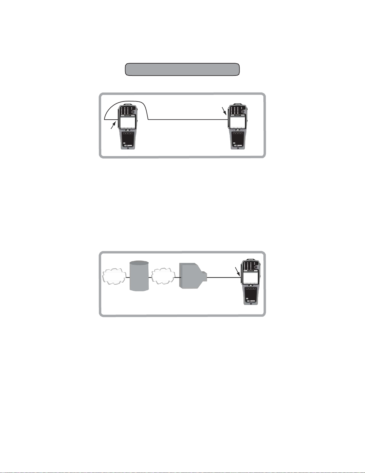
MTT-14B e_Manual D07-00-083P RevA00
Page 70 of 101
3
Applications
3.1 Loop Pr
equalification
Central Of
fice
Customer Premises
Use this
fore the DSLAM is setup and running in a particular location.
is also
but do not have direct
for this mode is:
•
3.2 STU-R Emulation-ISP Service
STU
STU-C STU-R
Figure 44 Dual-ended Modem
dual-ended
used
by
contract groups
STU-C and STU-R
proper G.SHDSL line coding in 2 or 4 wire
net
B-RAS
Router
Inter
2 or 4 Wire G.SHDSL
test during the
access
prequalification phase, be-
who
need
to the DSLAM. The
modem emulation;
ATM
DSLAM
STU
Emulation
to prequalify
application
link
turn-up utilizing
mode.
STU
2 or
4-wire
G.SHDSL
It
cir
cuits,
STU-R
Figure 45 STU-R
Use STU-R modem emulation during installation and service
verification
using the STU port on the
procedures. Connect
module
CO. This verifies the link can be
supported, and no errors occur. Applications in this mode are:
•
Achieve synchronization with DSLAM.
•
Link
measurements
•
PING to ISP.
like rate, noise margin, and
Emulation
the test set to the cable
and turn up the lin k with
established,
the bit rate can
attenuation.
pair
the
be
,

MTT-14B e_Manual D07-00-083P RevA00
Page 71 of 101
3.3 STU-R Emulation-Private Network Service
PDH
SDH
DSLAM
2 or
4-wire
G.SHDSL
STU
STU-R
Figure 46 STU-R Emulation-Private Network Service
Common applications in this mode include:
•
Achieve synchronization
•
Link
measurement
with DSLAM.
like rate, noise margin, and
attenuation.
3.4 STU-C Emulation
Customer
CPE
2 or
4-wire
G.SHDSL
STU
Figure 47 STU-C
Emulation
This
mode is used
installed
and to
to prequalif
troubleshoot
y circuits
before the STU-C is
faulty circuits.
Connect
and turn up the link.
STU-C
to the
CPE

MTT-14B e_Manual D07-00-083P RevA00
Page 72 of 101
3.5 Accept a New E1 Circuit
STU
Exchange
Verify
1.
disrupt service.
end.
2. From the module main menu, select
and
MODE: STUC E1, STUR E1, or E1
SOURCE:
Tx
FRAMING: As
CRC-4: As
TEST RATE:
Rx
TX CLOCK: INTERN
When finished,
From the module ma
3.
the
4. Connect the test set to the circuit as shown in Figure 48 and
press
the PAT SYNC LED is green.
rom the module main menu, select E1 MEASUREMENT,
5. F
press
company’s requirements for the
UP
measurement screens.
6. When finished,
and remove the loop at the far end of the
Figure 48 Accept a New E1
that the span is not in service. This acceptance test
There must be a
configure
as
follows:
TESTPAT
specified
specified
2.048M
PORT:
TERM
press
in me
desired
(F1)
test
pattern.
HISTORY
to
START (F3)
and PAGE-DN
acknowledge
and verify that the circuit performs to your
press
Customer
Premises
MON
Loopback
Span
Device
OUT
IN
loopback device
TEST
CONFIGURATION
by the circuit
by the circuit
design.
design.
ENTER.
nu, select TEST PATTERN and select
When finished,
press
ENTER.
any blinking LEDs.
service delivered.
(F2)
to access each of the individual
ESC to return to the
module
circuit.
Use
main
at the
Verify
PAGE-
menu
will
far
that

MTT-14B e_Manual D07-00-083P RevA00
Page 73 of 101
3.6 In-Service E1 Circuit Monitoring
Monitor Mode Bridge
STU
MON
OUT
IN
OR
Figure 49 In-Service E1 Circuit Monitoring
Mode
STU
1. This test may be
2. From the module main menu, select
configure
and
MODE: STUC E1, STUR E1, or E1
SOURCE:
Tx
FRAMING: As
CRC-4: As
TEST RATE:
Rx
PORT:
MONITOR or BRIDGE
TX CLOCK: INTERN
When finished,
If unsure of
Note:
MONITOR
Monitoring Point) access.
3. Connect the test set to the circuit as shown in Figure 49 and
press
HISTORY to
xamine the LEDs for information
4. E
•
SIGNAL
•
A valid framing type
•
A steady
is working but is
•
ALARM
•
AIS may
element transmitting to the test set has lost its
signal and has replaced it with the AIS signal.
6. From the module main menu, select E1 MEASUREMENT.
START (F3)
Press
company’s requirements for the service delivered.
performed
as
follows:
while the
TESTPAT
specified
specified
by the circuit
by the circuit
2.048M
press
ENTER.
what Rx PORT leve
should
be
used
when you have a PMP
acknowledge
should
be
green,
should
ERROR
or CODE LED indicates that the
experiencing trouble.
indicates a problem
indicate
a trouble
and verify that the span performs to your
span
is
in-service.
TEST
CONFIGURATION
design.
design.
l to use, then use BRIDGE.
any blinking
about
red
indicates
be
indicated.
the
no
LEDs.
cir
cuit:
signal.
on the far end of the
condition
where a
(Protected
circuit
cir
cuit.
network
incoming

MTT-14B e_Manual D07-00-083P RevA00
Page 74 of 101
3.7 Measuring E1 Signal Level
STU
Figure 50 Measuring E1 Signal
signal level
A
conjunction with one of the other
Select
1.
measurement
can be performed by itself
tests.
the Rx PORT level to use. The
measurement
performed using TERM, MONITOR, or BRIDGE. A 1111
MON
TX
RX
Level
or in
can
be
pattern
in Rx PORT TERM or BRIDGE provides the most accurate
results.
MONITOR generally
shows
a result of
about
-20 or
-30 dB. TERM will disrupt service. BRIDGE: Measurement
may be
degraded
by a low-quality
termination
at the
network
element terminating the E1 line.
The
2.
rest of this procedure will
use
the
TERM
mode for illustra
tive purposes. Verify that the span is not in service.
TEST
3. From the module main menu, select
configure
and
MODE: S
SOURCE:
Tx
FRAMING: As
CRC-4: As
TEST RATE:
PORT:
Rx
as
follows:
TUC E1, STUR E1, or E1
TESTPAT
specified
specified
by the circuit
by the circuit
2.048M
TERM
design.
CONFIGURATION
design.
TX CLOCK : INTERN
press
When finished,
ENTER.
4. Connect the test set into the circuit as shown in Figure 50
press
and
HISTORY to
5. From the module MAIN MENU, select E1
and press
START
6. Press PAGE-DN
displayed and read the signal level. Note that separate r
ings
are given
for the positive and
acknowledge
any blinking
LEDs.
MEASUREMENT
(F3).
(F2)
until the E1 ALARM/SIGNAL screen is
negative signals
so that you
ead
can get more accurate information on a faulty regenerator.
-
-

MTT-14B e_Manual D07-00-083P RevA00
Page 75 of 101
3.8 V.54 Channel Loopback Test
1. From the module main menu, select
and
configure
as
follows:
TEST
CONFIGURATION
MODE: STUC E1, STUR E1, or E1
SOURCE:
Tx
TEST RATE:
When finished,
TESTPAT
Nx64/2.048M (as required)
press
ENTER.
Modem
Figure 51 V.54 Channel Loopback Test
2. Connect the test set into the circuit as shown in Figure 51
press
and
HISTORY to
3. From the module main menu, select MODEM CONTROL
LOOPBACK CONTROL and
the far end device. The
cess or error.
4. From the module main menu, select
test.
pressing
run a BERT by
5. Stop the
6. From the module main menu, select MODEM CONTROL
LOOPBACK CONTROL and press LOOP-DN
down the far end device. The
success or error.
MUX
acknowledge
press
the F-key that
STATUS
ERR
line will indicate either
INJ
STATUS
E1 MEASUREMENT
STU
TX
RX
E1
any blinking
LEDs.
will
loop
suc
and
(F1)
to
loop
line will indicate either
>
up
-
>

MTT-14B e_Manual D07-00-083P RevA00
Page 76 of 101
3.9 Nx64 kbit/s Testing
Fractional
N can be
line are dedicated to the fractional E1 circuit, and the remaining
channels
revenue
Use the following
1. Verify that the fractional circuit is not in service. This test
disrupt service.
2. From the module main menu, select
and
MODE: STUC E1, STUR E1, or E1
Tx
FRAMING: As
CRC-4: As
TEST RA
is
If needed, see Section 2.3.3.
Rx
TX CLOCK: INTERN
Press
Note: AUTO
any of the active channels are transmitting an idle
3. C
4. Ensure that a loop is in place at the far end of the
Press
5.
6. Select
perform the acceptance test and verify the fractional service
performs to your company’s requirements for the service
delivered.
E1 circuits are circuits of data rate Nx64 kb it/s,
anywhere
from 1 to 31
channels. N channels
of the E1 line are either filled with an idle
traffic or framing
configure
SOURCE:
specified
TE:
Nx64K, the fractional
displayed.
PORT:
Manually
TERM
ENTER when
configuration
pr
as
TESTPAT
specified
information.
ocedure:
follows:
by the circuit
by the circuit
configure
configur
design.
SELECT TIME SLOT
the
ed.
may not yield
TEST
CONFIGURATION
design.
timeslots
proper channels
or
press
wher
of the
code, other
screen
AUTO.
code.
onnect the test set to the circuit as shown in Figure 48.
circuit.
HISTORY to
MEASUREMENT RESULTS
acknowledge
any blinking
and press
LEDs.
START (F3)
e
E1
will
if
to

MTT-14B e_Manual D07-00-083P RevA00
Page 77 of 101

MTT-14B e_Manual D07-00-083P RevA00
Page 78 of 101
4 Reference
4.1 PING Technology
The name PING is derived from the SONAR world where one
pings an
object
cept applies to the Internet world, where one pings an
and waits for its
present and that the connection is active.
The PING message is an ICMP (Internet Control Message
tocol)
message.
However,
in
several
different implementation schemes for IP over ADSL.
Application
Softwar
TCP/IP
RFC 1483
AAL5/A
ADSL
Classical IP over
Figure 52 Encapsulation Technologies for IP over ADSL
in the water and listens for its
echo
(reply). This verifies that the end
Both
IP can be
devices
encapsulated
must be using TCP/IP
onto the ADSL
ways. The following figure
Application
Software
TCP/IP
802.3 Ethernet
RFC 1483
AAL5/ATM AAL5/ATM
ADSL ADSL
TM
e
Ethernet over ATM PPP over ATM
ATM
echo.
physical layer
provides a summary
Application
Application
Software
TCP/IP
PPP
RFC 2364
Software
TCP/IP
PPP
RFC 2516
802.3 Ethernet
RFC 1483
AAL5/ATM
ADSL
PPP over Ethernet
This
con
addr
ess
device is
Pro-
protocol.
of
the
-
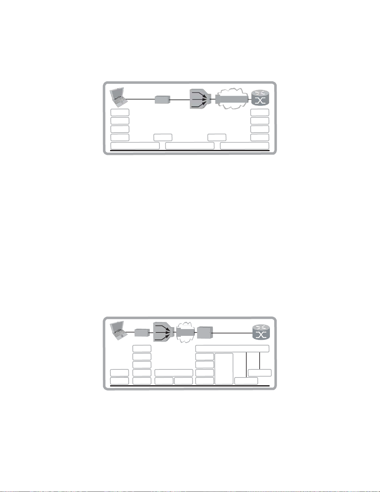
MTT-14B e_Manual D07-00-083P RevA00
Page 79 of 101
4.1.1 Classical IP over ATM (CLIPoA)
ADSL
DSLAM
ATM ATM
ADSL OC-3
TCP
IP
AAL5
ATM
ATM25
ATM
25.6
ATU-R
Figure 53 Classical IP over ATM
ATM-VC
ISP
TCP
IP
AAL5
ATM
Classical
speed
physical interface
interconnect
Classical
datagrams encapsulated in AAL5 using IETF RFC 1483
SNAP encapsulation.
4.1.2 Ethernet Frames over ATM (EoA)
In this case, the Ethernet frames are encapsulated into the ATM
Adaptation Layer 5
supports
RFC 1483 ‘Multi protocol Encapsulation over AAL
Figure 54
used
static with
of DHCP session management or it can use RFC 1483 Routed.
IP
over ATM is an
IETF
protocol which uses ATM’s high
ability in the Local Area Network. It
over Twisted Pair Cable (per ATM Forum)
in the
LAN
at the
speed
IP over
both routing
shows a sample configuration
in the field. In this
RFC
IP
802.3 ADSL ADSL OC-3 OC-3
ATM
reduces overhead
(AAL5)
using RFC 1483. The encapsulation
and bridged. This is based
case,
IP
address management
1483 Bridge encapsulation, dynamic with the use
A
TU-R
IP
802.3
1483
AAL5
DSLAM
ATM
ATM-VC
B-RAS
1483
AAL5
ATM
Figure 54 Ethernet over ATM
uses
ATMF
(ATM25.6)
of 25.6
Mbps.
by having IP and ARP
on the standard
5’.
of
Ethernet
IP Routing
802.3
LAN
Media
over ATM
WAN
can
ISP
Media
to
LLC/
be

MTT-14B e_Manual D07-00-083P RevA00
Page 80 of 101
4.1.3 PPP over Ethernet
(PPPoE)
over ATM
ATM
ATM-VC
B-RAS
PPP
2516
802.3
1483
AAL5
ATM
A
IP
PPP
2516
802.3 ADSL ADSL OC-3 OC-3
TU-R
IP
PPP
2516
802.3
1483
AAL5
DSLAM
Figure 55 PPP over Ethernet
PPPoE uses Ethernet networking
scheme designed
PPPoE enables
through
the standard RFC 2516 ‘PPP over
a single,
for multi-PC
multiple PCs to
shared
CPE using one PVC. This is
4.1.4 PPP over ATM (PPPoA)
PPPoA has a great advantage
PPPoE.
It is
based
on the
standard
ATM
ATM-VC
A
TU-R
LAN
IP
802.3 ADSL ADSL OC-3 OC-3
OR
DSLAM
DSL
Router
IP
PPP
2364
AAL5
Figure 56 PPP over ATM (PPPoA)
with PPP in an
homes
connect
Ether
net’.
in reducing the
RFC 2364 ‘PPP over
B-RAS
PPP
2364
ATM
ISP
IP Routing
802.3
WAN
Media
Media
LAN
(PPPoE)
encapsulation
and small businesses
to multiple
destinations
based on
overhead required
AAL
5’.
ISP
LAN
WAN
Media
Media
IP Routing
802.3
.
in

MTT-14B e_Manual D07-00-083P RevA00
Page 81 of 101
For PPP
likely
ist.
•
•
Authentication is commonly used since it provides security
the
with a user
to
or the CHAP authentication mechanisms. The PPP session is
opened with
LCP
manage the authentication of the user name and password.
4.1.5 PING Acronyms
Here are
monly encounter.
CHAP:
CLIPoA: Classical IP over ATM
DHCP: Dynamic Host
LCP: Link Control
LLC: Logical Link
PAP: Password Authentication
PPP: Point-to-Point
Point-to-Point over ATM PPPoE:
Point-to-Point over Ethernet PVC:
Permanent Virtual Cir
VCI: Virtual
VPI: Virtual Path
(PPPoE
be dynamic.
PPPoA
and
PPPoA),
However, static IP
has the following
IP address
management
address management
implementations
will most
can ex
of IP management:
Static IP address management over PPP.
Dynamic IP address management over PPP. In this case, the
IP address is requested and assigned at the time of the
nection.
con
for
connection.
open
a link with the ISP.
session
some
Challenge Handshake Authentication Pr
In the
name
the
Broadband-Remote Access Server (B-RAS). The
is
handled between
of the
case
of PPP,
and
password. These
Identification
acronyms
identification
will
be
is
required
can use either the PAP
the B-RAS and the PC (CPE)
and
abbreviations
you
otocol
Configuration Protocol
Pr
otocol
contr
in order
will
com
olled
Control
Pr
otocol
Pr
otocol
cuit
Channel Identifier
Identifier
PPPoA
:
-
-
to
-

MTT-14B e_Manual D07-00-083P RevA00
Page 82 of 101
4.2 E1 Technology Overview
This
section covers
technology; sampling a signal, converting this information into a
bitstream,
and dividing the
This section also
gies like MFR2 and
4.2.1 Technical Standards
E1
transmission technology
ogy standards. Such standards allow equipment designers and
service providers to ensure that various pieces of equipment are
compatible
and that
manner. The following standards cover many of the
aspects of E1 transmission
•
ITU G.703: Physical/electrical characteristics of interfaces.
•
ITU G.704: Synchronous frame
•
ITU G.706: Frame alignment and CRC.
•
ITU G.821: Error performance of a international
•
ITU G.826: Error performance
•
ITU M.550/M.2100 Getting an international connection
service.
•
Q.140:
•
Q.400: Concerns CAS
Concerns redundant copies
Consult these standards when you need detailed information on
particular aspects of E1 transmission
4.2.2
Basic Definitions
Binary Data: A signal which has
of zeros and ones.
Bit Stream: Binary Data which has
at a fixed
rate.
Channel: A single portion of the bit
bidirectional communication.
4.2.3 Converting a Voice Signal
To
transmit
The
analog
voice over a digital
voice signal must be
Then it must be
transmission. This conversion
Pulse Code Modulation as shown in Figure 57.
touches
converted
the
fundamental concepts
bitstream
upon the basics
CAS.
is
defined
networks operate
technology:
structur
and
(Channel
Associated Signaling).
been converted
stream
medium,
converted
to a bit
can be
in 2.048
into
segments (channels).
of signalling technolo-
by a
number
in a
predictable, r
of
es.
connection.
transmission
from
technology
quality control.
subrate channels.
.
into a
been placed
in a
which is available
like a 2.048 Mbit/s
into a binary
stream suitable
accomplished through
Mbit/s
technol
eliable
important
into
format
sequence
for
line.
format.
for
digital
-

V
olts
V
olts
MTT-14B e_Manual D07-00-083P RevA00
Page 83 of 101
Voice Signal
T
ime
Sampling
Pulse Amplitude Modulation
Figure 57 Converting a Voice
The Nyquist
twice the signal’s maximum frequency in order for the signal
be
reproduced
the maximum frequency is approximately 4000 Hz.
adequate clarit
must sample our 4000 Hz voice signal at a frequency of 8000
Hz (8000 samples/second).
The amplitude of the analog voice signal is sampled 8000 times
second.
per
‘word’. These 8-bit words occurring 8000 times per
a 64 kbit/s digital bit
The
8-bit code
analog sample to a companding characteristic.
is a formula which translates the amplitudes of the samples
the 8-bit
known as ‘A-law’ is
optimum signal-to-noise performance over a wide ranger of
transmission
noise ratio at the -20 dB
the encoding is done according to the Mu-Law. Therefore, the
companding law used for encoding the voice signal must
that for decoding, for distortion-free transmission.
theorem requires that the signal
without a loss of information. For voice
y for voice transmission bandwidth.
Each
amplitude
str
word is
value is
eam.
formed by comparing the amplitude
code words. Internationally, a companding characteristic
used.
The
levels. Linear
encoding provides a poorer signal-to-
level
typical of speech. In North America,
Quantization
T
ime
expressed
purpose
00101 101
101 101 10
11000100
Signal
be sampled at
to
signals,
This provide
Thus, we
as an 8-bit
code
second form
of th
e
This characte
risti
c
into
of A-law is to provide
match
s
4.2.4 2.048 Mbit/s Data
The E1 signal
(bitstream)
(2 048 000 bits per
by
combining
64 (kbit/s
32 individual 64 kbit/s
/Channel)
This 2.048 Mbit/s signal is the overall E1
Rate
is
second).
x 32
(Channels)
transmitted
This
transmission
bitstr
= 2048 kbit/s = 2.048
at a rate of 2.048
eams:
rate is
achieved
Mbit/s
transmission rate.
Mbit/s

MTT-14B e_Manual D07-00-083P RevA00
Page 84 of 101
4.2.5 Line Coding
Two common E1 line coding types are shown in Figure 58:
2.37V
0V
time
AMI Line
Coding
-2.37V
2.37V
1 1 0
0V
1 0 0 0 0 0
-2.37V
Note: This voltage is seen from a 75 Ω unbalanced connection.
time
HDB3 Line
Coding
Figure 58 AMI & HDB3 Line
AMI:
Alternate
Mark Inversion is
the simplest
ing formats. AMI is used to represent successive 1 values in a
bitstream with alternating positive and negative pulses. Figure
depicts these alternating pulses. AMI is not used in most 2.048
Mbit/s transmission
trings of data zeros.
long s
because synchronization loss
HDB3: This line coding format was adopted in order to eliminate
synchronization problems occurring with AMI. With
a string of four
string of
consecutive
pulses containing
zeros is
an intentional bipolar violation.
the far end equipment receives the E1 signal, it examines the
bit
stream
for
these
intentional bipolar
extracts the code and reconstruct the original data. The HDB3
code substitutions
ing
equipment
provide high pulse
is always able to maintain
the received signal. For example, in the code 1000 0000, HDB3
coding substitutes
General rules apply to the
tution
made
as well as the
bit.
If
there is an odd
polarity of V is the
ing it.
If
there is an even
polarity of B is
bipolar violations for the string of
substitutions.
is
governed
number
opposite
by the polarity of the last
of
pulses
number
same
as that of the bit
number
following the
of
pulses,
of
pulses,
to that of the bit
it and the polarity of V is the same as that of B. Refer to Figure
o see the
59 t
types
of HDB3 zero
substitution
Coding
of the two line
occurs during
HDB3 coding
replaced
code
density
with a
substitute
violations. It
so that the r
synchronization with
zer
The
particular
inserted bit,
previous violation
000V is
substituted; the
immediately preced
B00V is
inserted;
immediately preceding
codes.
eceiv
os.
substi
cod
then
the
-
58
,
As
-
-
-

MTT-14B e_Manual D07-00-083P RevA00
Page 85 of 101
Number
substitution).
of
pulses
(since last
Polarity of Previous Pulse
Even
(substitute
B00V)
Odd
(substitute
000V)
1 0 0 1 1 0 0 1
0 0 0 1 0 0 0 1
Figure 59 HDB3
Encoding
The E1
types
to the
4.2.6 Signal Levels
module
of HDB3
proper number
can be
configured
substitution codes,
of
pulses
since the last
Ideal Pulse Actual Pulse
Figure 60 Pulse Shape
to
detect
the one of the
even if they are not
substitution.
G.703 Mask
two
matched
Once a signal has
sembled
converted
into a bit
to
In Figure 59, a typical signal level for an E1 pulse with 75W im-
pedance
is either ± 2.37 volts (for a binary 1 value) or 0 volts (for
a binary 0 value).
each pulse transmitted would
in the real-world, each pulse is slightly distorted when generated
and more so when it travels down the line. In
of an ideal pulse is compared to an actual pulse.
An E1 pul
shape.
se might need to conform to a standardized pulse
This is often
‘mask’. A commonly used pulse mask is defined by ITU-T G.703,
it is
shown
in the G.703 Mask illustration in Figure
Note: For an E1 pulse with
is either ± 3 volts (for a binary 1 value) or 0 volts (for a binary
value) with real world values typically be ±
been encoded
stream,
actual
voltage levels
Real-world
determined
into a binary format and as-
the
pulses
values are typically ± 10%.
in the bit
suitable
stream
for E1
are
transmission.
Ideally,
be perfectly symmetrical. However,
Figure
60, the shape
by
comparing
it to a
60.
specified
120W impedance, the signal level
10%.
then
0

E 0 0 1 1 0 1 1
E 1 A
Sa
Sa
Sa
Sa
Sa
MTT-14B e_Manual D07-00-083P RevA00
Page 86 of 101
4.2.7 2.048 Mbit/s Framing
E1 transmission utilizes two types of framing:
ment
Signal)
is
necessary so
and MFAS
(MultiFrame
that the equipment r
Alignment
eceiving the E1 signal is able
to identify and extract the individual channels. PCM-31 uses FAS
framing and PCM-30 uses MFAS with FAS framing.
FAS (Frame Alignment Signal)
The 2.048
bered
Mbit/s frame consists
0-31). As
described previously, each
an individual 64 kbit/s
channel
of 32 individual time slots (num-
of
data.
In the FAS format, time slot 0 of every other frame is reserved
for the FAS pattern. Alternate frames contain the FAS Distant
Alarm indication bit
and other bits reserved
International use. Hence, there are 31 time slots into which data
can be
placed
as in Figure
61.
T
ime Slot 0
One 2.048 Mbit/s Frame
1
BITS
1 2 3 4 5 6 7 8
FAS (Frame
Signal).
time slot
for National an
... 31
Align
Framing
consists of
d
-
Notes:
• Even Frame: Contains FAS.
• Odd Frame: Contains NFAS.
• Sa: This bit is reserved for national use.
• E: Error indicator bit.
• A: Remote alarm indicator bit.
• 0011011: Frame alignment signal.
• (8 bits per timeslot)(8000 frames per second) = 2.048 Mbps
Figure 61 FAS Framing Format
FAS
does
not
accommodate
bit (c or Si) of
can be
used
these frames
for the CRC-4, Cyclic
enhanced performance monitoring is required. Therefore, when
CRC is
enabled
in TEST CONFIGURATION,
upon the CRC calculation
0 and 1. When CRC-4 is not
In FAS framing, the odd frames do not contain the frame
ment signal. The bits are
voice
is
reserved
channel
signalling. The
for
international
Redundancy Check-4, when
and should continually
enabled, these
defined
as
follows:
bits are set to 1.
use. It
these
bits
depend
change between
align-
first

TS 0
-------- TS 16
-------- TS 31
TS 0
-------- TS 16
-------- TS 31
TS 0
-------- TS 16
-------- TS 31
BITS BITS BITS
1 2 3 4 5 6 7 8
1 2 3 4
5 6 7 8
1 2 3 4
5 6 7 8
A B C
D
A B C
D
MTT-14B e_Manual D07-00-083P RevA00
Page 87 of 101
•
When CRC is
Check-4 performance monitoring.
bit may only be
•
The
second
•
Bit A is
enabled,
bit 1 is
changed
used
when CRC is
bit is set to 1 to avoid FAS signal
used
for the
Remote
(FAS) Distant Alarm. This bit is
for the Cyclic
When CRC is
disabled.
confusion.
Redundancy
enabled, this
set to 1 to indicate an alarm. It is set to 0 for no alarm.
• Spare bits (4-8): Are set to 1 for crossing an international border.
unused,
When
The first bits of frames 13 and 15 transmit the two E-bits, which
used to indicate CRC-4 errors. A 0 in this bit
rored
sub-multiframes;
MFAS (MultiFrame Alignment Signal)
their
settings
a 1
represents
are defined by
denotes
errorless received
ITU-T
G.704.
ar
received er-
frames.
e
FRM 0 FRM 1 FRM 2 FRM 3
---------
FRM
15
0 0 0 0 X Y X X
Notes:
• Frame 0, timeslot 16: 8 bit MFAS signal.
• Frames 1-15, time slot 16:
(4 signalling bits per channel)(30 channels) /
(8 signalling bits per frame timeslot 16) =
15 frames of timeslot, 16 signalling.
• Frame 0 TS 16 bits: MFAS = 0000
• NMFAS = XYXX, where X is spare bits. If this is not used,
then this is 1). Y is the MFAS remote alarm. If MFAS synch is
lost, then this is 1.
• Frames are transmitted with 30 voice channels in time slots 1
through 15, and 17 through 31.
• Timeslot 16 (TS16) contains A/B/C/D bits for signalling (CAS).
• MFAS multiframe consistes of 16 frames.
Ch 1
(TS-1)
A B C
Ch 16
(TS-17)
D
Ch 15
(TS-15)
A B C
Ch 30
(TS-31)
D
Figure 62 MFAS Framing Format
MFAS framing provides CAS (Channel-Associated
transmit
This
A/B/C/D bit
supervision
information for
method uses the 32 timeslot frame format including timeslot
0 for the FAS. This method also uses timeslot 16 for the MFAS
and the CAS. It
frames
to make up a
takes
16
When the MFAS frame is transmitted, all of the individual FAS
frames and framing information intact is left intact. The 16 FAS
frames are assembled together, dedicating timeslot
frame to MFAS framing information, then dedicating timeslot 16
of the
remaining
15
frames
to A/B/C/D bits as in Figure
Signalling)
each channel.
MultiFrame.
16 of the first
62.
to

TIME SLOT 0
Bit
s
MTT-14B e_Manual D07-00-083P RevA00
Page 88 of 101
CRC-4 Error Checking in a MultiFrame Format
M-
SM-
FRM
FRM
FRM
Bit 1 Bit 2 Bit 3 Bit 4 Bit 5 Bit 6 Bit 7 Bit 8
0
c1
0
0
1
1
0
1
c2
2
3
1
4
5
6
7
8
9
10
11
2
12
13
14
15
Notes:
• SMF-FRM+1: Sub-Multiframe #1.
• Sa: Spare bit reserved for national use.
• A: Remote Alarm (FAS: Remote Alarm Indication).
• Frame Alignment Signal Pattern: 0011011
• CRC-4 Frame Alignment Signal: 001011
• CRC multiframe is not aligned with MFAS timeslot 16 multiframe.
• SM-FRM 2: Sub-Multiframe 2
• E: E-bit Errors.
• c1, c2, c3, c4: CRC bits
0
c3
1
c4
0
c1
1
c2
1
c3
E
c4
E
0
1
0
1
0
1
0
1
0
1
0
1
0
1
Sa4
A
0
A
Sa4
0
A
Sa4
0
A
Sa4
0
Sa4
A
0
A
Sa4
0
A
Sa4
0
A
Sa4
1
Sa5
1
1
Sa5
1
1
Sa5
1
1
Sa5
1
1
Sa5
1
1
Sa5
1
1
Sa5
1
1
Sa5
Figure 63 CRC-4 Multiframe Format
A
CRC-4 (Cyclic Redundancy Check-4) is
mission to identify possible bit
errors.
often
CRC-4 allows the detection
of errors within the 2.048 Mbit/s signal while it is in
CRC-4 is
each sub-multiframe
the E1 data
Next it
sub-multiframe. R
ematical computation
CRC-4 bits which were
Next it
based
calculates
inserts
the CRC-4 bits in the CRC-4
compares
on a
mathematical calculation performed on
of
data.
The
equipment
the CRC-4 bits for one
eceiving equipment performs
on the
transmitted
the
transmitted
sub-multiframe.
in the next
CRC-4 bits to the
value. Discrepancies in the two values indicate a CRC-4 error.
0
0
0
0
0
0
0
0
1
Sa7
1
Sa7
1
Sa7
1
Sa7
1
Sa7
1
Sa7
1
Sa7
1
Sa7
E1 trans-
Sa6
Sa6
Sa6
Sa6
Sa6
Sa6
Sa6
Sa6
used in
service.
which
originates
sub-multiframe.
positions
the
in the
reverse math
It
examines the
sub-multiframe.
calculated
1
Sa8
1
Sa8
1
Sa8
1
Sa8
1
Sa8
1
Sa8
1
Sa8
1
Sa8
next
-

MTT-14B e_Manual D07-00-083P RevA00
Page 89 of 101
Two things to
the performance of an E1 circuit. Each individual CRC-4 error
does
not
errors within
4 error for the block. Also, it is
such
that the new CRC-4 bits are
the original CRC-4
CRC-4 error
errors within an in-service system. On an in-service system, it is
generally not
there is no pattern synch. Bit error measurement is used on an
out-of-service system because
CRC-4 uses a multiframe structure consisting of 16 frames,
as shown in Figure 63. However, the CRC-4 multiframe is
necessarily al
tiframe can be divided into 2 sub
are labeled SMFRM1 and SMFRM2 and consist of 8 frames
apiece.
sub-multiframe.
The CRC-4
and
inserted
across the E1 span.
When
the terminating equipment calculates
should transmit
it
end equipment of the error.
E-bit Performance Monitoring
When the terminal equipment of a 2.048 circuit is optioned
CRC-4
E-bit
performance monitoring
terminating equipment transmits
Mbit/s l
transmission is a relatively new feature in 2.048 transmission.
Therefore,
transmit
cations
When
this type of terminal equipment detects
it
error,
will
terminal. Test set 2,
E-bit errors by plugging into a
that the test set can not see the
errors and CRC errors
set
can
E-bit error
to be reliably
point on the
remember
necessarily correspond
the
same sub-multiframe will lead to only one CRC-
when using CRC-4 errors to
to a single bit error. Multiple
possible
that errors could
calculated
bits.
checking
possible
igned with the
is a
convenient method
to
measure
the
MFAS
the
results
multiframe.
actual
multiframes
Four bits of CRC information are
bits are calculated for
into the following
each sub-multiframe, buffered,
sub-multiframe
an E-bit to the far end, thus informing the
transmission,
E-bit
transmission
of the circuit is now
an E-bit
ine, when it
it is likely that the
the E-bit error information
of the network to see if this is
respond
receives
a CRC-4 error.
embedded equipment does not
correctly. Check
available.
by transmitting an E-bit
shown
in Figure 64, will be able to see
protected monitoring
actual code
introduced
at the trouble point. The
see only the E-bit errors transmitted
transmission
monitored
circuit.
allows a 2.048 Mbit/s
for
transmission performance
determine
to be the
same as
of identifying
bit errors
because
are more precise.
Each
CRC-4 mul
(SMFRM).
associated
to be
an
error using CRC-4,
may also be
with
transmitted
enabled.
possible. The
error on the
However,
E-bit
the
specifi
an
incoming CRC-4
error
toward
the othe
point.
errors, framing
by Terminal
B. Thus,
in-service
from
bit
occur
bit
not
These
each
far
for
2.048
error
the
Note
bit
test
cir
cuit
any
-
-
r
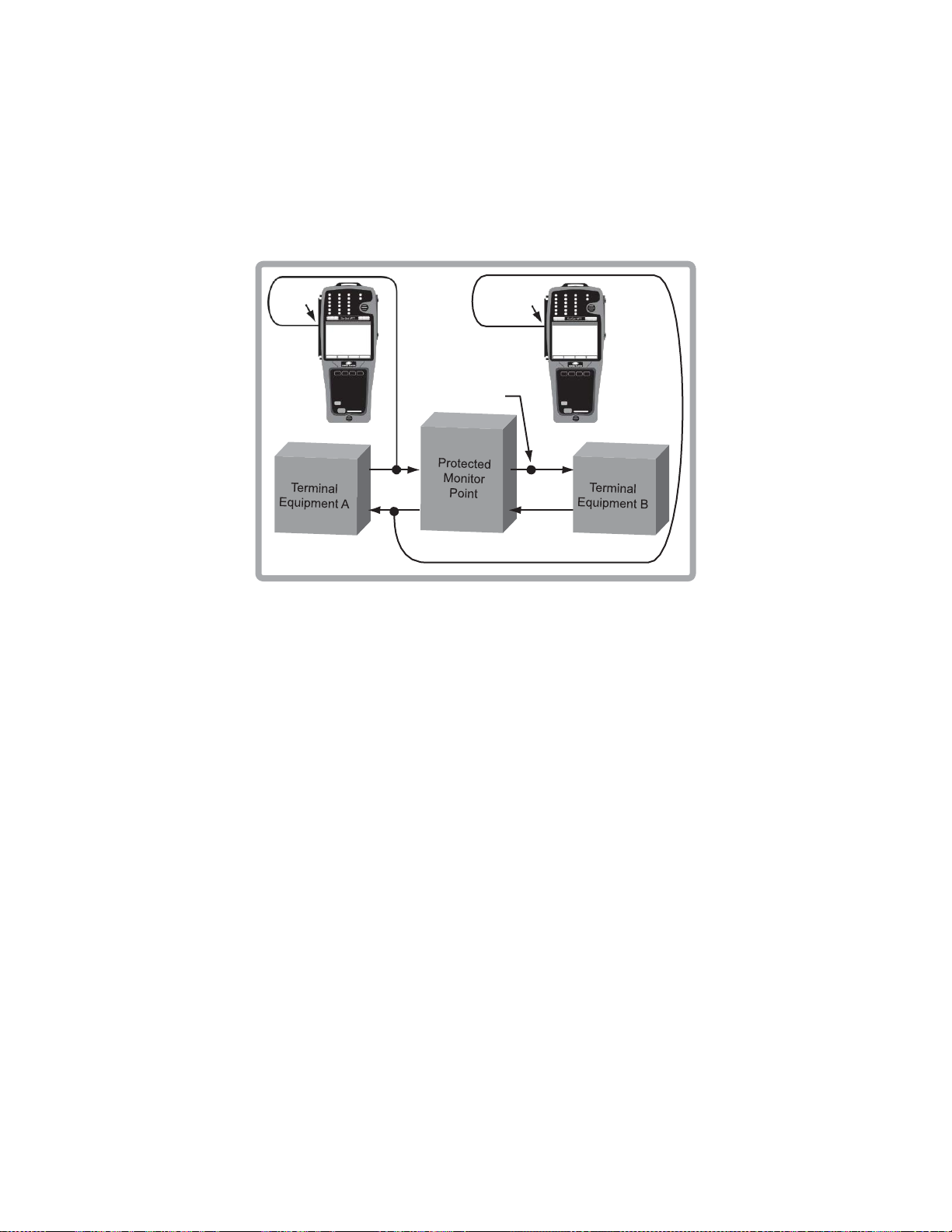
MTT-14B e_Manual D07-00-083P RevA00
Page 90 of 101
Without E-bit error
can be reliably
complete circuit failure, the test set will see either loss of signal,
alarm indication signal, or remote alarm
STU
No
Errors
transmission,
determined
Trouble Point
only a
complete
circuit failur
at any point on the circuit. With
indication.
STU
E-Bit
Error
e
a
Test Set 1 Test Set 2
CRC
Error
E-Bit
Error
Figure 64 In-service E-bit Performance Monitoring

MTT-14B e_Manual D07-00-083P RevA00
Page 91 of 101

MTT-14B e_Manual D07-00-083P RevA00
Page 92 of 101
5 General Information
5.1 Testing and Calibration Statement
VeEX Inc.
and verified
manufacturing and test procedure(s). These formal
dures are designed to assure that the product meets its required
specifications.
This
usage, periodic calibration
product
the
product
and repair.
5.2 Express Limited Warranty
A.
Hardware Coverage. COMPANY warrants hardware
against defects
warranty period COMPANY will, at its sole option, either
refund of CUSTOMER’S purchase price without interest, (ii)
repair said products, or
prove to be
ucts which COMPANY
COMPANY by CUSTOMER, along with
of
freight prepaid.
B. Software and Firmware Coverage. COMPANY warrants
ware media and firmware materials against defects in material
and
at its sole option, either
price without interest,
software
provided, however, that such products which COMPANY
elects
TOMER, along with
twenty (20) days of
addition, during the warranty period, COMPANY will
without
original
during the warranty period. COMPANY does not warrant
represent
case where
IS,” COMPANY’S
inaccurate copy of the original material. This warranty does
not cover upgrade or enha
firmware.
certifies that this
according
product has
fails during the
purchase,
workmanship.
to
charge
product specifications
no user-adjustable settings. During normal
can be
or firmware
replace
that all
returned
in
defective; provided, however,
within twenty
to CUSTOMER, all fixes and
COMPANY
product
to the
is not a
self-verification
to the
materials
(iii)
replace hardware products
elects
(20)
During the warranty period
(i)
refund of
(ii)
repair said products, or
products
must be
acceptable evidence
request
software defects
has licensed a software product
obligation
ncements to product software and
was
manufactur
applicable VeEX Inc. Inc.
requirement. However,
test, during power
manufacturer
and
workmanship.
to
replace
days of
which prove to be
returned
by COMPANY, freight
sold which COMPANY
will be limited to
must be
acceptable evidence
request
CUSTOMER’S
to COMPANY by
of
will be
ed,
tested
pr
oce
if
the
up,
for
evaluation
products
During
that
such prod
returned to
by
COMPANY
COMPANY
(iii)
purchase, within
prepaid.
patches
corrected.
replacing an
the
which
soft
will,
pur
chase
replace
defective;
CUS
pr
ovide,
to
the
issues
In
any
“AS-
-
(i)
-
,
-
s
-
In
or

MTT-14B e_Manual D07-00-083P RevA00
Page 93 of 101
C. Period. The warranty period for Hardware, Software and
Firmware
TOMER. The COMPANY may also sell warranty extensions
or provide a warranty term of three years with the original
sale, which provide a longer coverage period for the test set
chassis, software
express
term.
D. Only for
for the benefit of CUSTOMER and not for the benefit of
subsequent purchaser
E. LIMITATION ON WARRANTY. THIS CONS
AND
RESPECT
THERE
PLIED.
WARRANTIES
PARTICULAR PURPOSE.
A
THIS AGREEMENT WITH RESPECT TO A PRODUCT, I
ING COMPANY’S LIABILITY FOR FAILURE AFTER REPEATE
EFFORTS
ORDER
IN NO EVENT EXCEED THE PURCHASE PRICE OR
FEE
EVENT
TIAL, INDIRECT,
NATURE WHATSOEVER, ARISING
THE SALE
ING BUT NOT LIMITED TO
RELATED TO LOSS OF BUSINESS, LOSS OF PROFIT,
OF GOODWILL, INJURY TO REPUTATION,
DOWNTIME, REPAIR OR REPLACEMENT, OR C
BACKS OR OTHER DEBITS FROM CUSTOMER OR ANY
CUSTOMER
F. No Guaranty, Nonapplication of Warranty. COMPANY does
not guaranty or warrant that the operation of hardware,
ware, or firmware
the warranty shall not apply to defects resulting
(1)
(2) CUSTOMER-supplied software or interfacing;
(3)
(4)
(5) Improper site preparation or maintenance;
(6)
will
be One (1) Year from date of
and firmware, in which
limited warranty
CUSTOMER.
will
COMPANY
or
licensee
EXCLUSIVE WARRANTY
TO
HARDWARE, SOFTWARE
ARE NO OTHER
COMP
ANY SPECIFICALLY
OF
MERCHANTABILITY
WARRANTIES, EXPRESS
COMPANY’S
TO INSTALL EQUIPMENT IN GOOD WORKING
OR TO
FOR THAT
REPAIR
OR
PRODUCT,
NOR SHALL COMPANY IN ANY
BE LIABLE FOR ANY
OR
SPECIAL DAMAGES
OF
THE MERCHANDISE HEREUNDER,
OF CUSTOMER.
will
be
uninterrupted
Improper
or
inadequate maintenance
Unauthorized modification
Operation outside
product;
the
Improper installation
of the
environmental specifications for
by
CUSTOMER.
apply to said
makes
of any
shipment
case
the
specified warranty
this warranty
mer
chandise.
to
terms
TITUTES THE SOLE
MADE BY COMPANY WITH
AND FIRMWARE.
OR IM
DISCLAIMS THE
AND
LIABILITY
IMPLIED
FITNESS
UNDER
NCLUD-
REPLACE EQUIPMENT,
LICENSE
INCIDENTAL,
CONSEQUEN-
OF ANY KIND OR
FROM OR
RELATED
INCLUD
DAMAGES ARISING
FROM OR
OVERHEAD,
HARGE-
or
error-free.
Further
from:
by
CUSTOMER;
or
misuse;
or
CUS
of
the
only
any
FOR
SHALL
TO
LOSS
soft
-
-
D
-
-
,

MTT-14B e_Manual D07-00-083P RevA00
Page 94 of 101
Index
A
Alarm Status Screen
ATTN; 11
LOSW; 11
SNR; 11
Applications
Accept a New Circuit; 71
In-Service Circuit Monitoring; 72
IP Echo Response; 46
IP PING Test; 43
IP Trace Route; 45
Loop
Measuring Signal Level; 73
Nx64 kbit/s Testing; 75
STU-C Emulation; 70
STU-R Emulation-ISP Service; 69
STU-R
V.54
C
Calibration Statement;
Connector Panel
PAYLOAD
D
DHCP: PING Passed; 19
E
E1 Measurement
General information; 53
E1 Measurement-Common Measurements
%AS; 54
%DGRM; 54
%EFS; 54
%ES; 54
%SES; 55
%UAS; 55
+/- RxLVL; 55
+LVL, -LVL; 55
AISS; 54
BER; 54
BIT; 54
CLK SLIP; 54
CODE; 54
CRC; 54
DGRM; 54
EBER;
Prequalification;
Emulation-Private
Channel Loopback
and STU ports; 5
54
69
91
Network Service; 70
Test; 74

MTT-14B e_Manual D07-00-083P RevA00
Page 95 of 101
EBIT; 54
EFS;
54
ES; 54
FALM; 55
FE; 55
Hz/PPM; 55
LOFS; 55
LOSS; 55
Lpp; 55
MAX Hz, MIN Hz; 55
MFAL; 55
RCV Hz; 55
RxCLK; 55
SES;
55
SLIP; 55
UAS; 55
E1 Measurements
E1 Alarm/Signal Screen; 57
E1 Frequency Screen; 56
E1 G.821 Screen; 57
E1 G.826 Screen; 58
E1 M.2100/550 Screen; 57
E1 Status Screen; 56
E1 Summary Screen; 56
E1 Technology; 81
2.048 Mbit/s Data Rate; 82
2.048 Mbit/s
Framing
FAS or MFAS; 85
Basic Definitions; 81
Converting a Voice Signal; 81
CRC-4 Error
Performance
E-bit
Coding
Line
Checking
in a MultiFrame Format; 87
Monitoring; 88
AMI or HDB3; 83
Signal Levels; 84
Technical Standards; 81
Echo Response Screen; 46
Entering a User ID/Password; 22
een
Error Injection Scr
COUNT; 62
MODE
RATE;
BURST or
ramming a 10-6 Bit Error Rate; 63
Prog
62
Programming a Burst of 10 Errors; 63
TYPE
CODE, BIT, BIT + COD, CRC-4,
FRAME,
or E-BIT; 62

MTT-14B e_Manual D07-00-083P RevA00
Page 96 of 101
F
Figures
01 Connector Panel; 5
02 Test Set LED Panels; 6
03 Module Menu Tree; 7
04 STU-x
Configuration Screens;
05 Modem Status Screens; 9
06 Alarm Status Screen; 11
07 SHDSL
System Loopback Screen;
08 LLC-BRG PING Setup Screen; 15
09 CLIPoA
Configuration Screen;
10 LLC PING Test Passed; 18
11 DHCP: IP Address Assigned; 19
12 DHCP: PING Passed; 19
13 PPPoA PING Setup Screen; 20
14 PPP PING Results Screen; 23
15 Profile
Configuration Screen;
16 VCC Scan Screen; 25
17 OAM Cell Generation Screen; 29
18 OAM Connection; 31
19 OAM Cell Statistics Screen; 31
20 IP
21 Profile
Configuration Screens;
Configuration Screens;
22 DHCP IP Screens; 39
23 ARP IP Screens; 40
24 PPP IP Screens; 41
25 PING Test Screen; 43
26 Trace Route Screen; 45
27 Echo Response Screen; 46
28 STUx E1 and E1
Configuration Screens;
29 Select Time Slot Screen; 48
30 STUx E1 Modem Status Screens; 50
31 STUx E1 Al
arm Status Screen; 52
32 E1 Status Screen; 56
33 E1 Summary Screen; 56
34 E1 Frequency Screen; 56
35 E1 G.821 Screen; 57
36 E1 Alarm/Signal Screen; 57
37 E1 M.2100/550 Screen; 57
38 E1 G.826 Screen; 58
39 Test Pattern Screen; 59
40 Error Injection Screen; 62
41 View/Store/Print List Screen; 64
42 Filename Character Screen; 66
43 Profile List
Screen;
67
44 Dual-ended Modem Emulation; 69
45 STU-R Emulation; 69
8
12
17
24
34
38
47

MTT-14B e_Manual D07-00-083P RevA00
Page 97 of 101
46 STU-R
47 STU-C Emulation; 70
48 Accept a New E1 Span; 71
49 In-Service E1 Circuit Monitoring; 72
50 Measuring E1 Signal Level; 73
51 V.54
52 Encapsulation Technologies for IP over ADSL; 77
53 Classical IP over ATM; 78
54 Ethernet over ATM; 78
55 PPP over Ethernet
56 PPP over ATM
57 Converting a Voice Signal; 82
58 AMI & HDB3 Line Coding; 83
59 HDB3 Encoding; 84
60 Pulse Shape; 84
61 FAS Framing Format; 85
62 MFAS Framing Format; 86
63 CRC-4 Multiframe Format; 87
In-service
64
I
Configuration
IP
AUTHENTICATION
PAP, CHAP, AUTO, or NONE; 35
DNS SERVER
NONE, MANUAL, or AUTO; 36
Entering a User ID/Password; 37
GATEWAY;
LOCAL IP; 36
PASSWORD;
Profile
Creating,
USER
VCI; 36
VPI; 36
Configuration
IP
ENCAPSULATION
LLC, VC M
IP TYPE
STATIC,
MODE
PROFILE,
33
IP Status
ARP IP Screens; 40
DHCP IP Screens; 39
PPP IP Screens; 41
Emulation-Private
Channel Loopback
(PPPoA);
E-bit
Performance
Scr
een
Network Service; 70
Test; 74
(PPPoE);
79
79
Monitoring; 89
36
37
Setup
Saving, Editing, and Invoking; 38
ID; 37
Scr
eens
UX, or AUTO; 35
DHCP, or DYNAMIC; 35
LLC-BRG, LLC-RTE, CLIPoA, PPPoE, or PPPoA;

MTT-14B e_Manual D07-00-083P RevA00
Page 98 of 101
L
LEDs; 6
LLC PING Test Passed; 18
M
Menu Tree; 7
Modem Status Screens
ATTENUATION;
ERRORS;
CRC
CUR SNR MARGIN; 10
ERROR
SEC; 10
ET; 9
RATE;
LINE
LOSW SEC; 10
MAX SNR MARGIN; 10
MIN SNR MARGIN; 10
PAYLOAD RATE;
SEVERE ERR
UNAVAILABLE
N
NNI VPI and VCI
O
OAM Cell Generation Screen
#CELL; 30
# LOST; 30
# Rx; 30
# Tx; 30
CLP; 29
GFC; 29
ROUNDTRIP
CUR, AVG, MAX, and MIN; 30
TIMEOUT;
TYPE
F4SGAIS, F4SGRDI, F4SG_LP, F4EEAIS, F4EERDI,
F5SGAIS, F5SGRDI, F5SG_LP, F5EEAIS , F5EERDI,
LP,
F5EE_LP;
VCI; 29
VPI; 29
OAM Cell Statistics Screen
# OF OAM
ET; 31
OAM
F4SGAIS, F4SGRDI, F4SG_LP, F5SGAIS, F5SGRDI,
F4EEAIS, F4EERDI, F4EE_LP, F5EEAIS,
LP,
F5EE_LP;
PAGE;
31
ST; 31
10
10
9
9
SEC; 10
SEC; 10
Values;
(ms)
30
29
REQUEST;
32
27
F4EE_
or
31
F5SG_
and F5EERDI,

MTT-14B e_Manual D07-00-083P RevA00
Page 99 of 101
TIME; 31
TOTAL;
VCI; 32
VPI; 32
OAM Connection; 31
P
PING Setup Screens
AUTHENTICATION
DESTINATION
ENCAPSULATION
GATEWAY;
IP ADDRESS
LOCAL IP; 16, 17, 22
MODE
PASSWORD;
USER
VCI; 16, 17, 21
VPI; 15, 17, 21
PING Technology; 77
Classical IP over ATM
Ethernet Frames over ATM
PING Acronyms; 80
PPP over ATM
PPP over Ethernet
PING Test Screen; 43
PPPoA and PPPoE Mode PING Results; 23
Profile
Editing a
Invoking a Profile; 24
Profile List
LOAD,
PTI Decode
S
SH
STU-x
LN
PL
STANDARD
32
PAP, CHAP, or AUTO; 20
IP; 16, 17, 22
LLC; 17
LLC, VC MUX, or AUTO; 15, 20
16
STATIC
STATIC
PROFILE,
or DHCP; 16
or DYNAMIC; 21
LLC-BRG, LLC-RTE, CLIPoA, PPPoE, or PPPoA;
14
22
ID; 22
(CLIPoA);
(EoA);
(PPPoA);
Configuration
Saved
Scr
Profile; 24
een
79
(PPPoE)
Scr
een
over ATM; 79
STORE, RENAME, DELETE,
Values;
System Loopback Screen;
DSL
Configuration
RATE
(Line
RATE
(Payload
28
Rate);
Rate);
Scr
8
eens
8
(per ITU G.991.2)
ANNEX-A
or -B; 9
78
78
and LOCK/UNLOCK; 67
12

MTT-14B e_Manual D07-00-083P RevA00
Page 100 of 101
WIRES
2 and 4-WIRE; 8
STUx E1 Alarm Status Screen
ATTN; 52
LOSW; 52
SNR; 52
STUx E1 and E1
Configuration
CRC-4; 48
FRAMING
PCM-30, PCM-31, or
RX PORT
TERM,
BRIDGE,
or MONITOR; 49
Select Time Slot Screen
Selection Procedures; 48
TEST
RATE
2.048M or Nx64K; 48
TX CLOCK
Rx or
INTERN;
49
TX SOURCE
TESTPAT
or LOOP; 47
STUx E1 Modem Status Scr
ATTENUATION;
ERRORS;
CRC
50
50
CUR SNR MARGIN; 50
ET; 50
RATE;
LINE
50
LOSW SEC; 51
MAX SNR MARGIN; 50
MIN SNR MARGIN; 50
PAYLOAD RATE;
SEVERE ERR
UNAVAILABLE
System Settings Scr
DISPLAY
LOOP
RECEIVE
ALL EOC
ATTEN THRESHOLD;
EOC SNR
SEND EOC SNR
SNR MARGIN
50
SEC; 50
SEC; 51
een
MESSAGES;
OFFSET;
OFFSET;
THRESHOLD;
TRANSFORMER RATIO;
T
T
ables
VCI
01 UNI VPI and
02 NNI VPI and VCI
03 PTI Decode
Values;
Values;
Values;
Scr
eens
UNFRAME;
eens
13
13
13
13
13
13
26
27
28
47
 Loading...