

MTTplus-523_e-manual, D07-00-117P RevA00

Table of Contents
MTTplus-523_e-manual, D07-00-117P RevA00
1.0 About this User Manual
2.0 Safety Information
3.0 Introduction
3.1 MTTplus-523 Overview
3.2 Evolution of Residential DSL to G.fast
4.0 Basic Operations
4.1 Touch-Screen Display
4.2 Battery
4.3 Connector Panel
5.0 DSL/G.fast Overview
6.0 DSL/G.fast Measurements
7.0 Common Functions
8.0 ReVeal Software
9.0 Warranty and Software
10.0 Product Specification
11.0 Certification and Declarations
12.0 About VeEX
Go back to top

1.0 About This User Manual
MTTplus-523_e-manual, D07-00-117P RevA00
This user manual is suitable for novice, intermediate, and experienced users and is intended to help you successfully use the
features and capabilities of the different modules for test platforms. It is assumed that you have basic computer experience and
skills, and are familiar with IP and telecommunication concepts, terminology, and safety.
Every effort was made to ensure that the information contained in this manual is accurate. However, information is subject to
change without notice. We accept no responsibility for any errors or omissions. In case of discrepancy, the web version takes
precedence over any printed literature.
(c) Copyright 2006-2017 VeEX Inc. All rights reserved. VeEX, VePAL are registered trademarks of VeEX Inc. and/or its affiliates
in the USA and certain other countries. All trademarks or registered trademarks are the property of their respective companies.
No part of this document may be reproduced or transmitted electronically or otherwise without written permission from VeEX Inc.
This device uses software either developed by VeEX Inc. or licensed by VeEX Inc. from third parties. The software is confidential
and proprietary of VeEX Inc. The software is protected by copyright and contains trade secrets of VeEX Inc. or VeEX's licensors.
The purchaser of this device agrees that it has received a license solely to use the software as embedded in the device, and the
purchaser is prohibited from copying, reverse engineering, decompiling, or disassembling the software.
For more technical resources, visit the VeEX Inc. web site at
this product, call or e-mail our customer care department for customer support. Before contacting our customer care department,
have the product serial number and software version ready. Please locate the serial number on the back of the chassis. Please
provide this number when contacting VeEX customer service.
Customer Care:
Phone: + 1 510 651 0500
E-mail:
Website:
Go back to top Go back to TOC
customercare@veexinc.com
www.veexinc.com
www.veexinc.com. For assistance or questions related to the use of

2.0 Safety Information
MTTplus-523_e-manual, D07-00-117P RevA00
Safety precautions should be observed during all phases of operation of this instrument. The instrument has been designed to
ensure safe operation however please observe all safety markings and instructions. Do not operate the instrument in the
presence of flammable gases or fumes or any other combustible environment. VeEX Inc. assumes no liability for the customer's
failure to comply with safety precautions and requirements.
Lithium-ion Battery Precautions
Lithium-ion (Li-ion) battery packs are compact and offer high capacity and autonomy, which make them ideal for demanding
applications, like providing long lasting power to portable test equipment. For safety reasons, due to their high energy
concentration, these batteries packs and products containing them must be used, charged, handled, and stored properly,
according to the manufacturer’s recommendations.
Li-ion battery packs contain individual Li-ion cells as well as battery monitoring and protection circuitry, sealed in its plastic
container that shall not be disassembled or serviced.
The test set unit's battery pack is also fitted with a safety connector to prevent accidental short circuits and reverse polarity.
Always charge the unit's battery pack inside the test platform battery bay using the AC/DC adapter supplied by VeEX.
Do not charge or use the battery pack if any mechanical damage is suspected (shock, impact, puncture, crack, etc).
Do not continue charging the battery if it does not recharge within the expected charging time
Storage: For long term storage, the battery pack should be stored at 20°C/68°F (room temperature), charged to about 30
to 50% of its capacity. Spare battery packs should be charged and used at least once a year to prevent over-discharge
(rotate them regularly).
It is recommended to charge and use battery packs at least every three months. Battery packs shall not go without
recharging (reconditioning) for more than six months.
After extended storage, battery packs may reach a deep discharge state or enter into sleep mode. For safety reasons, Liion batteries in deep discharge state may limit the initial charging current (pre-recharge) before starting their regular fast
charging cycle. The pre-charging state may take several hours.
Air transportation of Li-ion batteries is regulated by United Nations' International Air Transportation Association (IATA)
Dangerous Goods Regulations and by country-specific regulations. Please check local regulations and with common
carriers before shipping Li-ion battery packs or products containing relatively large Li-ion battery packs.
Electrical Connectors
Telephone lines may carry dangerous voltages. Always connect the electrical test ports to known test interfaces which carry low
level signals.
Test modules could be affected by electrostatic discharge. To minimize the risk of damage
when replacing or handling test modules, make sure to follow proper ESD procedures and
dissipate any electrostatic charge from your body and tools and the use proper grounding
gear.
Perform all work at a workplace that is protected against electrostatic build-up and
discharging.
ESD: Electrostatic Discharge Sensitive Equipment

Go back to top Go back to TOC
MTTplus-523_e-manual, D07-00-117P RevA00
Never touch any exposed contacts, printed circuit boards or electronic components.
Always store test modules in ESD protected packaging.
Wear ESD protection and grounding gear when:
Inserting, extracting, or handling test modules.
Connecting or disconnecting cables from modules or platform.
3.0 Introduction
MTTplus-523_e-manual, D07-00-117P RevA00
3.1 MTTplus-523 Overview
The MTTplus-523 module offers Customer Premise Equipment emulation mode for G.fast, VDSL2, and ADSL2+, to verify
broadband service performance for xDSL and G.fast networks.
3.2 Evolution of Residential DSL to G.fast
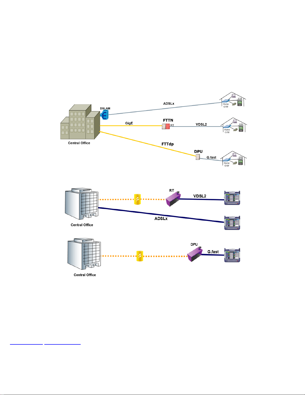
DSL Network Types
CPE Emulation for ADSLx, VDSL2, and G.fast
As DSL technology continues to improve, the copper wire length from a broadband provider's distribution point to the customer
premise has decreased, providing even greater speeds to customers.
ADSL relied solely on existing copper telephone wire infrastructure, connecting from the Digital Subscriber Line Access
Multiplexer (DSLAM) at the provider's central office to reach customer premises. With VDSL, fiber from the CO is deployed to a
DSLAM at an optical node (FTTN) closer to the customer premise, further shortening the length of copper cabling. VDSL2 and
G.fast are capable of closing the distance from a distribution point (FTTdp) to a few hundred meters of the end subscriber. G.fast
supports speeds of 150 Mbps to 1 Gbps depending on the distance from the distribution point.
Go back to top Go back to TOC
4.0 Basic Operation
MTTplus-523_e-manual, D07-00-117P RevA00
For information on Basic Operations, Home menu, Launching Test Applications, and other features specific to the MTTplus Host
Chassis, refer to the MTTplus Platform Manual. The following sections describe basic operations for the MTTplus-523 module.
4.1 Touch-Screen Display
The LCD supports touch-screen operation. To operate the touch-screen, use the stylus located in the top cover to navigate the
menus and tabs. Please observe the following precautions:
Never use excessive pressure on the touch-screen as this may damage its functionality.
Never use sharp objects such as a pen, screwdriver etc. as this may damage the surface.
Clean the surface of the touch screen using a soft cloth and mild detergent only. Do not use alcohol.
Go back to top Go back to TOC
4.2 Battery
The MTTplus chassis is equipped with an intelligent Li-ion rechargeable battery pack which is located in the rear of the unit. The
battery will be partially charged upon delivery, so it is recommended to charge the battery fully before use. Please charge the
battery at room temperature to preserve its life and to obtain maximum charge. The battery is charged during operation provided
the unit is connected to the AC Mains using the supplied AC adapter. Removing the battery, while the unit is powered on is not
recommended - this may result in damage. Charge the battery by connecting the AC Main adapter to the power jack on the left
side.
Go back to top Go back to TOC
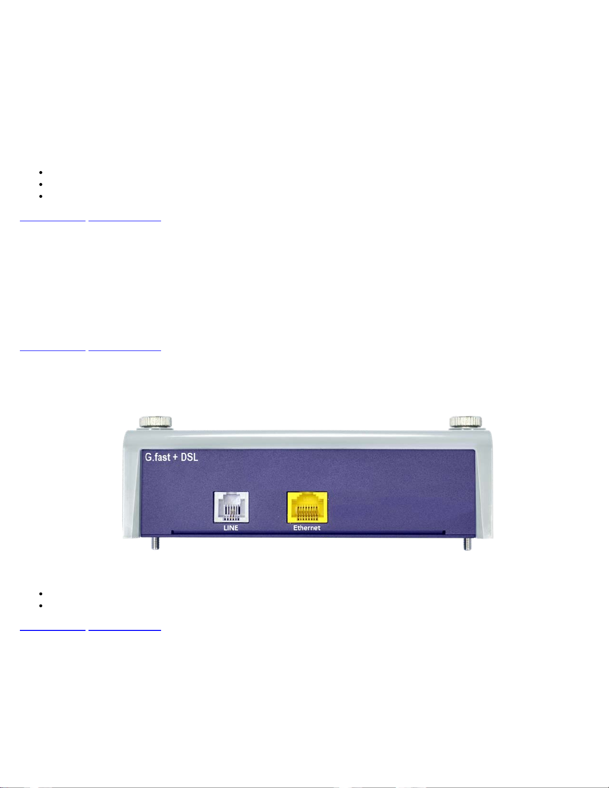
4.3 Connector Panel
The MTTplus-523 module supports CPE mode:
RJ11 LINE interface for G.fast and DSL
RJ45 Ethernet Port, for DSL to PC Pass Through mode
Go back to top Go back to TOC
Connector Panel

5.0 DSL/G.fast Overview
Also known as ITU-T G.992.5, the standard extends the capability of basic ADSL by doubling the number of downstream tones
MTTplus-523_e-manual, D07-00-117P RevA00
ADSLx and VDSL2 technology uses the copper pair between the exchange or street cabinet and the customer premises. The
usable bandwidth is extended from 4 kHz to 2.2 MHz in the case of ADSL2+ and up to 30 MHz for VDSL2. Extended bandwidths
make the copper pair far more susceptible to faults, impairments and other degradation. Modem Emulation testing at this layer
not only
assessed.
The MTTplus-523 offers the following test functions:
Go back to top Go back to TOC
ANSI
Defined by the American National Standards Institute (ANSI) Telecommunications Committee, T1.413 was the first standardized
ADSL specification. The underlying modulation is Discrete Multi-Tone (DMT) line code which divides the bandwidth of the
standard two wire copper wire used in the PSTN into 256 separate 4.3125kHz wide bins called sub-carriers. Even though each of
these 256 sub-carriers or tones can support a modulation of up to 15 bits, the maximum achievable downstream data rate is
actually 8.128 Mbit/s due to error checking and related overhead data. In the upstream direction, a maximum of 30 sub-carriers is
used, each tone being modulated with up to 15 bits providing a maximum theoretical throughput of just over 1.5 Mbit/s.
provides information about the copper's performance, but connection to the DSLAM or customer's modem can also be
Emulates customer modem (XTU-R or G.Fast FTU-R) to prove that synchronization or link up with DSLAM / DPU is
possible
Provides key link performance statistics - measures downstream bit rate, upstream bit rate, max bit rate, relative capacity,
signal to noise (SNR) margin, and attenuation among other measurements
Carrier Tone statistics in both graphical and table format
Error metrics and Events Table
DMT
Also referred to as ITU G.992.1, the standard expands the usable bandwidth of existing copper telephone lines to rates up to 12
Mbit/s downstream and 1.3 Mbit/s upstream. Discrete Multi-Tone (DMT) mode, divides the ADSL signal into 255 carriers (bins)
spaced in multiples of 4.3125kHz. The DMT spectrum has 224 downstream frequency bins and up to 31 upstream bins.
In Annex A systems where Voice (POTS) is used on the same line, the frequency spectrum can be outlined as follows:
0-4kHz is allocated to Voice traffic
4-25kHz is an unused guard band
25-138kHz is for Upstream data
138-1107kHz is for Downstream data (ADSL)
138-2208kHz is for Downstream data (ADSL2+)
ADSL2
Also known as ITU-T G.992.3, the standard extends basic ADSL data rates to 12 Mbit/s downstream and 3.5 Mbit/s upstream;
however, actual speeds are dependent on line quality - the most significant factor being loop length.
ADSL2+
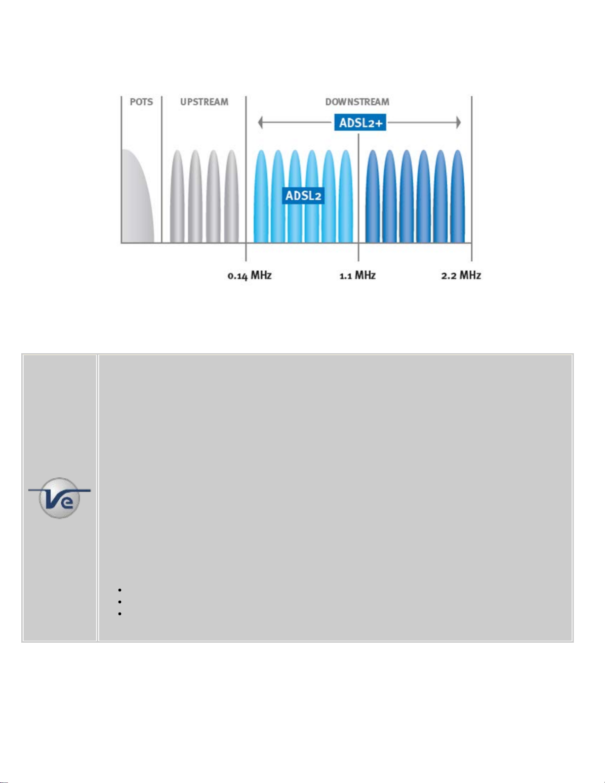
providing data rates as high as 24 Mbit/s downstream and 1 Mbit/s upstream depending on loop length. ADSL2+ can also be
used to reduce crosstalk because it provides the capability to use only tones between 1.1 MHz and 2.2 MHz, thus masking the
MTTplus-523_e-manual, D07-00-117P RevA00
downstream frequencies below 1.1 MHz and associated interference. This is also referred to as Spectral Masking.
ADSL2+ Frequency Spectrum
VDSL2
Frequency configuration options of 8.5 MHz, 12 MHz, 17.7 MHz, and 30 MHz are set automatically depending on DSLAM
settings.
Note: Impulse Noise Protection (INP)
Electrical appliances and installations at customer premises often generate short bursts of noise of relatively
high amplitude. These bursts, called impulse noise, are electromagnetically coupled into the digital
subscriber line, degrading performance and in some cases disrupting service. The ADSL2/+ standard
introduced a parameter called Impulse Noise Protection (INP), that allows operators to select the maximum
impulse length that the DSL system can correct.
VDSL2 uses the same parameter and when implemented, an INP value between 2 and 16 can correct
errors from noise impulses ranging from 250µs to 3.75ms in length.
INP is a key feature in most IPTV video deployments and enables better Video QOS by minimizing the
effects of Impulse Noise.
The INP value for the interleaved channel can be set by the user and is expressed in symbols. For
example, an INP value of 1 means that 1 symbol can be corrected i.e. a burst of noise for 1 symbol
duration can be corrected without errors. One symbol equals 250µs, therefore an INP of 1 correlates to a
correction time of 250µs.
The Impulse Noise Protection (INP) or interleave depth is defined by the S and D parameters where:
S is the Interleave DMT symbols per FEC code word (1, 2, 4, 8, 16)
D is the Interleave depth (1, 2, 4, 8, 16, 32, 64)
Interleave delay can vary from 4.25 to 263.75 msec

Note:
MTTplus-523_e-manual, D07-00-117P RevA00
Annexes: Similar to ADSL and ADSL2+, VDSL2 includes regional bandplan annexes that specify PSD
Masks which are designed to coexist with other services. Annex A specifies bandplans for the North
American and enables VDSL2 to be deployed with traditional POTS telephony. Annex B specifies bandplans
for Europe and and enables VDSL2 deployment with underlying POTS and ISDN services. Annex C allows
VDSL2 to coexist with TCM ISDN services, found primarily in Japan.
Bandplans: VDSL2 is a true worldwide standard which has numerous configuration profiles and bandplans
to meet regional service provider requirements. The frequency bandwidth has increased from 12 MHz to 30
MHz, with options for 8.5 MHz, 12 MHz, 17.7 MHz, and 30 MHz spectrums.
The standard also defines asymmetric (Plan 998) and symmetric (PLan 997) bandplans for the transmission
of upstream and downstream signals.
Profiles: To simplify configuring network equipment, the standard defines profiles tailored for different
regional deployment architectures. There are eight profiles which define power options, bandwidths and
minimum data rates for each profile. The profiles are depicted in the table below.
G.fast

G.fast is ideally suited for Fiber to the Distribution Point (FTTdp), where pure FTT deployment costs remain high. G.fast enables
telecommunications service providers to stay competitive with cable operators, offering Gigabit+ services based on DOCSIS 3.x.
MTTplus-523_e-manual, D07-00-117P RevA00
G.fast highlights:
Aggregate data rate targets of up to 1 Gbps for short copper loops, less than 300 meters.
Based on ITU-T standards G.9700 and G.9701
Spectrum: frequency range from 2 MHz to 106 MHz
Tone spacing of 51.75 kHz; 2048 maximum number of tones, 12 Bits per Tone
212 MHz profile planned for the future for faster max rates
Uses Time-Division Duplexing (TDD) while traditional DSL uses Frequency-Division Duplexing
Enables flexible configuration of carriers shared by downstream and upstream, improving overall throughput
Vectoring for far-end crosstalk cancellation
Go back to top Go back to TOC

6.0 DSL/G.fast Measurements
MTTplus-523_e-manual, D07-00-117P RevA00
The DSL synchronization process for the MTTplus-523 is outlined as follows:
1. Activation, Discovery or Handshaking: Powering on the unit takes the DSL modem into activation and
acknowledgement phase, also known as handshaking. The goals of this are to determine which tones can be used and
how many bits can be assigned to each tone. Initialization typically uses two pilot tones to begin activation. Normally the
modem initiates the process when it is turned on and connected to the DSL line. Messages are sent using the pilot tones
to ensure that both ends are ready for transceiver training process.
2. Training: DSLAM measures and adjusts the power output to equalize the circuit. Unless configured otherwise, it
negotiates the fastest possible speed based on local loop conditions.
3. Channel Analysis: DSLAM tells the modem which options are configured and sends a predefined medley of tones so the
modem can report its signal-to-noise ratio.
4. Exchange: DSLAM sends the minimum signal-to-noise ratio and decides on the power output per tone.
5. Showtime: Initialization concludes in which the line is active and higher layer protocols, such as ATM, can begin
negotiation to transfer data over the connection. Showtime indicates that the port is working properly and synchronized.
The following measurements and parameters are displayed in the various tabs:
Line Status: Displays all measurements related to the DSL layer
Errors: Displays line signal alarms/errors that have occurred
Tones: Displays graphs and tables of carrier tone measurements: bits per tone, SNR per tone, HLOG per tone, and QLN
per tone
Events: Displays a log of all events that have occurred on the link since the test was started or measurement was cleared
or reset
Go back to top Go back to TOC
6.1 Setup
Setup tab
Modem Type:
XTU-R Mode
The test set will try to synchronize with the far end DSLAM in either ADSLx or VDSL2 mode.
G.Fast FTU -R Mode
The test set will try to synchronize with the far end G.fast DPU.
Select the desired mode and press Retrain to initiate testing.

Go back to top Go back to TOC
MTTplus-523_e-manual, D07-00-117P RevA00
6.2 Line Status
The current measurements displayed include the following:
Rate (kbps): Downstream and Upstream rate
Max (kbps): Maximum Downstream and Upstream rate
Capacity (%): Ratio of the actual rate versus the maximum bit rate
SNR Margin (dB): Signal to Noise Ratio margin
Attenuation (dB): Difference in the power level transmitted at the near end and received at the far end
Delay (ms): Interleave delay
INP (sym): See the note on Impulse Noise Protection
Depth (fm): Interleave depth
Tx Power: Transmitting power output is typically the level needed to achieve the noise margin configured in the DSLAM
Mode: Indicates the current test mode
Line Status
Line Status
G.fast Line Status

G.Fast Mode lists the following key G.fast measurements:
MTTplus-523_e-manual, D07-00-117P RevA00
Net Data Rate (kbps): Current achieved data rate
Expected Throughput Rate (kbps): The rate available in Showtime assuming full protection against an impulse noise
environment
Aggregate Rate: The sum of Downstream and Upstream rates
SNR Margin (dB): Maximum dB increase in equalized noise or maximum dB decrease in equalized signal that a system
can tolerate and maintain a BER of 1E-7
Start (ST) and duration time (ET), DSL synchronization status, ADSLx/VDSLx mode and profile, and estimated length are
displayed in a separate table.
DSL Modem Status
The DSL Modem Status icon indicates whether Showtime is in effect
No Showtime
Showtime status achieved
Go back to top Go back to TOC
6.2 Errors
Errors tab

Line and channel performance measurements include the following:
MTTplus-523_e-manual, D07-00-117P RevA00
CRC: Received CRC-8 code word does not match the code word transmitted. A count of the superframes that contained
CRC.
Forward Error Correction (FEC): Count of near end Reed-Solomon forward error correction anomalies for the interleaved
or fast data streams.
Header Error Control (HEC): Count of near end Header Error Control anomalies for the interleaved or fast data streams.
A CRC algorithm is used for checking and correcting an error in the ATM cell header. ATM equipment checks for an error
and if possible will correct it.
Errored Second (ES): Count of 1-second intervals with one or more CRC-8 anomalies summed over all received
channels, one or more LOS defects, one or more SEF defects, or one or more LPR defects
Severely Errored Seconds (SES): An Errored Second is any second containing one or more CRC anomaly, or one or
more Los(s) or Severely Errored Frame (self) defect(s)
Unavailable Seconds (UAS): Count of 1-second intervals for which the xDSL line is unavailable. The xDSL line becomes
unavailable at the onset of 10 contiguous SES which are included in unavailable time. Once unavailable, the xDSL line
becomes available at the onset of 10 contiguous seconds with no SES. However these 10 seconds with no SES are
excluded from unavailable time
Retrain: Press to resynchronize the modem.
Tap Reset to reset error counters.
On - line Reconfiguration (OLR)
During initial modem link up, a signal to noise measurement is made for each tone and the bit distribution is optimized to deliver
the desired bit rate. During showtime, modems constantly monitor the SNR/tone. On-line reconfiguration, specified in ITU-T
G.992.3, allows the DSL system to autonomously maintain operations within defined operation parameters. If changes in the line
or environment conditions occur (e.g. noise, interference, or cross talk), on-line reconfiguration processes adjust bit distribution
and data rates to optimize bandwidth.
Below are a few types of reconfiguration processes:
Bit Swapping: Reallocates bits and transmission power among allowed sub-carriers without changing bit rate. If a tone
degrades in quality, a bit swap command re-allocates bits to another tone or removes them completely.
Seamless Rate Adaptation (SRA): Reconfigures the total data rate by modifying the bits and gains, data frame
parameters, and DTU size without any service disruption or bit errors.
Fast Rate Adaptation (FRA): Provides fast adaptation of the bit rate, which can be used to lessen unexpected SNR loss
in cases of abrupt changes in the channel.
G.fast Near End Performance Counters
G.Fast Errors

G.fast mode displays the same errors as other ADSLx/VDSLx modes along with the followings near end performance counters:
MTTplus-523_e-manual, D07-00-117P RevA00
RTX-TX:Retransmitted frames may be sent to mitigate impulse noise in place of FEC or interleaving
RTX-Uncorrected RTX
Seamless Rate Adaptation (SRA)
Fast Rate Adaptation (FRA)
Go back to top Go back to TOC
6.3 Tones
Carrier tone measurements of tables and graphs aid the detection of copper faults that degrade DSL service quality. Graphs and
tables of carrier tone measurements are displayed in the Tones tab. Select a tone measurement from the side panel to view.
Viewing Exact Measurements on a Graph
Bits per Tone Graph
To find the exact measurement on a graph such as bit count and frequency of a specific tone, tap on the graph to move the
marker to the exact location. In the image above, the marker is at Tone 147, displaying its frequency (kHz) and the measured
raw SNR (dB).
Zoom In/Zoom Out for Graphs

The graph can display two different scales using Zoom In:
MTTplus-523_e-manual, D07-00-117P RevA00
The first scale displays all the tones on the same screen.
Tap Zoom In to display a smaller range of tones on screen. Move the pointer past 127 to view tones 128-255 in one
screen. Press Zoom Out to return to the original view displaying all the tones on the graph.
The Table displays tone measurements in a tabular format. Use the up/down arrows to scroll through the list of tones.
Go back to top Go back to TOC
6.3.1 Bits per Tone
This tab displays the bits per tone distribution used by the modem to transmit at the provisioned rate. Bits allocated per tone are
displayed as a graph or table. The graph is a useful visual tool to quickly identify interference or cross talk issues. It provides
valuable insight to ADSL spectrums or VDSL2 channel plan implemented.
Frequency Division Duplexing (FDD) in ADSL/VDSL is used to divide upstream and downstream bandwidth.
Discrete Multitone (DMT) Overview
In traditional VDSL2/ADSLx, Discrete Multitone (DMT) divides the signal into multiple carriers (bins) centered in multiples of
4.3125 kHz. The spectrum of each bin overlaps with its neighbors, i.e. it is not confined to a 4.3125 kHz wide channel because
the orthogonality of COFDM makes this possible without interference. Up to 15 bits per symbol can be encoded on each bin on a
good quality line. Each tone (bin) represents a 4.3125 kHz bandwidth and is used to transfer up to 15 bits in a single direction. In
VDSL2 Bandplan 30a, the tone bandwidth is increased to 8.625 kHz.
In contrast, G.fast has a tone spacing of 51.75 kHz and typical maximum of 12 bits per tone. The usable spectrum for G.fast is up
to 106 MHz.
ADSL, G.fast Comparison
Specifications VDSL G.fast
Full form Very high bit rate digital subscriber line Fast access to subscriber terminals
Frequency Up to 30 MHz 2-106 MHz, 2-212 MHz (future)
Maximum data rate
100 Mbps in both upstream and downstream
(VDSL2)
1 Gbps over distance of 70 meters
800 Mbps over distance of 100 meters
500 Mbps over old shielded type of cable
(distance of 100 meters)
Modulation type DMT (Discrete multi-tone modulation) e.g. OFDM
(Orthogonal Frequency Division Multiplexing)
Number of subcarriers
in a FFT
4000 2000 (in 106 MHz profile)
OFDM
Duplexing method FDD (Frequency Division Duplex) TDD (Time Division Duplex)
OFDM symbol time Approximately 250 µs (in 17 MHz profile) Approximately 20 µs
Vectoring method
Using ITU-T G.993.5
Supported along with adaptations required for
high frequency
Transmit power It depends on profile, 14.5 dBm 4 dBm
FEC type
Bits per DMT
frequency carrier
Impulse Noise
Protection
RS Coding (Reed Solomon Coding), trellis coding
15 (in VDSL2) 12
Available in VDSL2 Available
RS Coding (Reed Solomon Coding), trellis
coding
Standard ITU-T G.993.2, ITU-T G.993.5 ITU G.9700, G.9701

Interpreting the Results
MTTplus-523_e-manual, D07-00-117P RevA00
The lower frequency tones represent the bandwidth used for the upstream signal. The higher frequency tones at the right
show the frequencies used for the downstream signal.
The bits should drop to zero after the end of the upstream. This is the buffer between the upstream and downstream
signals. The actual size of this buffer varies.
If there is a major drop in bits in either the downstream or upstream section, this may indicate that there is a possible
interferer at that frequency. For example, if there is a major drop at 772 kHz, this may represent an interfering T1 signal.
Bits per Tone Graph
Tone Allocations in ADSL/2+
Go back to top Go back to TOC
6.3.2 SNR per Tone
This feature measures the Signal to Noise Ratio (SNR) for each downstream tone used by the modem to transmit the
provisioned rate. This can be displayed as a graph or as a table.
During initial modem link up, a signal to noise measurement is made for each tone and the bit distribution is optimized to deliver
the desired bit rate. During showtime, modems constantly monitor the SNR/tone and the bit distribution is adjusted to optimize
bandwidth based on noise, interference and cross talk. If a tone degrades in quality, a bit swap command adjusts the bit
allocation for that particular tone and these bits are either re-allocated to another tone or removed completely.
As with all transmission lines, signal quality depends primarily on the attenuation and SNR. The frequency of the bin can
therefore determine how many bits can be encoded, i.e. SNR can differ from bin to bin. Generally speaking, 1 bit can be encoded
reliably for each 3dB of available dynamic range above the noise floor e.g. a bin with a SNR of 21dB would be able to carry 7

bits. However, due to the face that a minimum of 2 bits (QAM-4) are encoded per bin, the SNR of any single bin cannot drop
below 6dB.
MTTplus-523_e-manual, D07-00-117P RevA00
Raw SNR per Tone
Go back to top Go back to TOC
6.3.3 HLOG
HLOG provides an attenuation vs carrier bin frequency graph. The frequency response curve can depict the presence of Bridge
Taps, which can have a characteristic magnitude dip. A clean Hlog curve's slope will decline gradually and evenly.
"Clean Line" HLOG Graph with No Bridge Taps
Dips on Curve May Indicate Bridge Taps

Go back to top Go back to TOC
MTTplus-523_e-manual, D07-00-117P RevA00
6.3.4 Quiet Line Noise (QLN)
QLN provides a quiet line noise vs. carrier bin Spectrum graph. This can help detect the presence of RF interference on the
copper pair under test.
QLN
Go back to top Go back to TOC
6.3.5 Events
The Events tab displays a date and time log of events such as synchronization status and errors that occur during testing.
Events

Go back to top Go back to TOC
MTTplus-523_e-manual, D07-00-117P RevA00

7.0 Common Functions
MTTplus-523_e-manual, D07-00-117P RevA00
The following functions are common to all VeEX test sets:
Tools tab
Tool
Utilities
Files
Go back to top Go back to TOC

8.0 ReVeal Software
MTTplus-523_e-manual, D07-00-117P RevA00
For more information on using the ReVeal CX300 software, refer to the user manual on the VeEX website.
Go back to top Go back to TOC

9.0 Warranty and Software
MTTplus-523_e-manual, D07-00-117P RevA00
Warranty Period: The warranty period for hardware, software and firmware is three (3) years from the date of shipment to the
customer. The warranty period for battery pack, LCD, LCD touch panel, LCD protective cover, and accessories (including, but not
limited to patch cords, AC adaptor, SFP, USB adaptors, carrying case, carrying pouch) is limited to one (1) year.
Hardware Coverage: VeEX Inc. warrants hardware products against defects in materials and workmanship. During the warranty
period, VeEX Inc. will, at its sole discretion, either
Repair the products
Replace hardware which prove to be defective
provided that the products that the customer elects to replace are returned to VeEX Inc. by the customer, along with Proof of
Purchase, within thirty (30) days of the request by the customer, freight prepaid.
Software Coverage: VeEX Inc. warrants software and firmware materials against defects in materials and workmanship. During
the warranty period, VeEX Inc. will, at its sole discretion, either
Repair the products
Replace software and/or firmware which prove to be defective
provided that the products that the customer elects to replace are returned to VeEX Inc. by the customer, along with proof of
purchase, within thirty (30) days of the request by the customer, freight prepaid.
Additionally, during the warranty period, VeEX Inc. will provide, without charge to the customer, all fixes, patches and
enhancements to the purchased software, firmware and software options. VeEX Inc. does not warrant that all software or
firmware defects will be corrected. New enhancements attached to a software option require the option to be purchased (at the
time of order or the time of upgrade) in order to benefit from such enhancements.
Limitations: The warranty is only for the benefit of the customer and not for the benefit of any subsequent purchaser or licensee
of any merchandise (hardware, software, firmware and/or accessories).
Revoking the warranty: VeEX Inc. does not guarantee or warrant that the operation of the hardware, software or firmware will
be uninterrupted or error-free. The warranty will not apply in any of the following cases:
Improper or inadequate maintenance by the customer
Damage due to software installed by the customer on the unit without prior authorization (written) from VeEX Inc.
Unauthorized alteration or misuse
Damage occurred from operating the unit outside of the environmental specifications for the product
Improper installation by the customer
Go back to top Go back to TOC

10.0 Product Specifications
MTTplus-523_e-manual, D07-00-117P RevA00
The most recent product specifications can be downloaded here from the VeEX website.
Go back to top Go back to TOC

11.0 Certifications and Declarations
MTTplus-523_e-manual, D07-00-117P RevA00
What is CE?
The CE marking is a mandatory European marking for certain product groups to
indicate conformity with the essential health and safety requirements set out in
European Directives. To permit the use of a CE mark on a product, proof that the
item meets the relevant requirements must be documented.
Use of this logo implies that the the unit conforms to requirements of European
Union and European Free Trade Association (EFTA). EN61010-1
Click here for CE Declaration of Conformity relating to VeEX products
What is RoHS ?
RoHS is the acronym for Restriction of Hazardous Substances. Also known as
Directive 2002/95/EC, it originated in the European Union and restricts the use of
specific hazardous materials found in electrical and electronic products. All
applicable products imported into the EU market after July 1, 2006 must pass
RoHS compliance.
Go back to top Go back to TOC
Click here for ROHS Statement relating to VeEX products

12.0 About VeEX
MTTplus-523_e-manual, D07-00-117P RevA00
VeEX, Inc., the Verification EXperts, is an innovative designer and manufacturer of test and measurement solutions addressing
numerous technologies. Global presence through a worldwide distribution channel provides uncompromised product support.
Visit us online at
VeEX Incorporated
2827 Lakeview Court
Fremont, CA 94538
USA
Phone: +1 510 651 0500
Fax: +1 510 651 0505
www.veexinc.com for latest updates and additional documentation.
Customer Care
Phone: + 1 510 651 0505
Email:
Go back to top Go back to TOC
customercare@veexinc.com
 Loading...