

Please direct all questions to your local VeEX Sales Office, Representative, Distributor or contact VeEX Technical
Support at www.veexinc.com.
No part of this manual may be reproduced, translated into a foreign language, or be transmitted electronically without
prior agreement and written consent of VeEX Incorporated as governed by International copyright laws. Information
contained in this manual is provided “as is” and is subject to change without notice. Trademarks of VeEX
Incorporated have been identified where applicable, however the absence of such identification does not affect the
legal status of any trademark.
Copyright © 2018 VeEX Incorporated. All rights reserved. MPA_e_manual_D07-00-129P_RevA00
MPA USER MANUAL
The Verification Experts
Software Feature Set 8.2
MPA_e_manual_D07-00-129P_RevA00
1

MPA_e_manual_D07-00-129P_RevA00

Table of Contents
MPA_e_manual_D07-00-129P_RevA00
Table of Contents
Getting Started .............................................................................................................. 11
Getting Started .......................................................................................................... 11
General Information ................................................................................................... 11
General Information Overview................................................................................ 11
Safety Guidelines ................................................................................................... 12
Copyright ................................................................................................................ 14
Customer Technical Support .................................................................................. 15
Warranty and Return Policies ................................................................................ 16
Return Shipping Instructions .................................................................................. 17
Configuring the IP Address ........................................................................................ 19
Configuring the IP Address Overview .................................................................... 19
Changing the IP Address with a USB Flash Drive.................................................. 21
Changing the IP Address with the Remote GUI Client ........................................... 26
Changing the MCH module’s IP Address ............................................................... 28
Remote Client Application ......................................................................................... 34
Remote Client Application Overview ...................................................................... 34
DLI Remote Client Requirements........................................................................... 35
Remote Client Installation ................................ ...................................................... 36
DLI Remote Client Removal ................................................................................... 37
Automating the DLI Remote Client Icon ................................................................. 38
Troubleshooting the Remote Client Application ..................................................... 40
VNC Connection ........................................................................................................ 41
iii

Table of Contents
MPA_e_manual_D07-00-129P_RevA00
Virtual Network Computing (VNC) Connection ...................................................... 41
VNC Viewer Configuration ..................................................................................... 42
Multiple Remote VNC Desktops ............................................................................. 46
Common Function Buttons ........................................................................................ 52
Common Function Buttons ..................................................................................... 52
Error Insert ............................................................................................................. 53
Stopping a Test ...................................................................................................... 53
Restarting a Test .................................................................................................... 54
Presets Function .................................................................................................... 54
Saving and Printing Statistics and Settings Reports .............................................. 55
Test Setup Button .................................................................................................. 58
Saving a Customized Settings Configuration ......................................................... 59
Restoring a Settings Configuration or Factory Defaults ......................................... 60
Clearing LED History and Resetting Results .......................................................... 61
Locking/Unlocking Screen Access ......................................................................... 62
Shutdown or Reboot the Processor from the GUI .................................................. 63
Common Tasks.......................................................................................................... 65
Common Tasks Overview ...................................................................................... 65
Software Upgrade .................................................................................................. 66
Timed Licenses ...................................................................................................... 68
MPA Shutdown Procedure ..................................................................................... 69
Fiber-Optic Cleaning Procedure ............................................................................. 72
Understanding Test Units .......................................................................................... 74
iv

Table of Contents
MPA_e_manual_D07-00-129P_RevA00
Understanding Test-Units ...................................................................................... 74
MPM Test Module Cards and Slot Locations ......................................................... 75
Lock Icon Overview ................................................................................................ 77
Locking and Unlocking a Test Unit ......................................................................... 79
Adding Notes to a Test Unit ................................................................................... 80
MPA Chassis ................................................................................................................. 83
MPA Chassis Overview ............................................................................................. 83
MPA 1st Generation Chassis (5-Slots): .................................................................. 83
MPA 2nd Generation Chassis (5-Slots): ................................................................ 83
MPA 3rd Generation Chassis (6-Slots): ................................................................. 84
MPA Rackmount Installation ...................................................................................... 85
MPA Chassis Dimensions ...................................................................................... 85
Chassis Mounting Brackets .................................................................................... 86
How to install the chassis into a rack ..................................................................... 87
MPA Power Connections ........................................................................................... 87
For the 110v/220v AC Power Supply: .................................................................... 88
For the -48v DC power chassis: ............................................................................. 89
EMI Shielding, Airflow, Air Filter and Fan Trays ........................................................ 90
EMI Shielding and Airflow Warning ........................................................................ 90
Dual Cooling Units (Fan Trays) .............................................................................. 91
Air Filter Swap ........................................................................................................ 91
Swapping and Inserting new test modules ................................................................ 91
Test Module Removal ............................................................................................ 92
v

Table of Contents
MPA_e_manual_D07-00-129P_RevA00
Test Module Insertion ............................................................................................. 92
SCM-210 (System Controller Module) ....................................................................... 94
MCH (MicroTCA Carrier Hub) .................................................................................... 95
AM4022 Processor .................................................................................................... 97
MPM-10G Test Module Overview .............................................................................. 98
MPM-100G Test Module Overview .......................................................................... 101
MPM-100AR Test Module Overview ........................................................................ 103
MPM-400G Test Module Overview .......................................................................... 106
Protocol Tabs .............................................................................................................. 111
Protocol Processor Tabs ......................................................................................... 111
MLD Tab .................................................................................................................. 111
MLD Tab Overview .............................................................................................. 111
Screens and Function Descriptions ...................................................................... 116
Specific Tasks ...................................................................................................... 172
OTN Tab .................................................................................................................. 177
OTN Tab Overview .............................................................................................. 177
Screens and Function Descriptions ...................................................................... 179
OTN Specific Tasks ............................................................................................. 257
SONET Tab ............................................................................................................. 271
SONET Tab Overview .......................................................................................... 271
Screens and Function Descriptions ...................................................................... 272
SONET Specific Tasks ......................................................................................... 374
SDH Tab .................................................................................................................. 391
vi

Table of Contents
MPA_e_manual_D07-00-129P_RevA00
SDH Tab Overview .............................................................................................. 391
Screens and Function Descriptions ...................................................................... 392
SDH Specific Tasks ............................................................................................. 501
Packet Tab .............................................................................................................. 519
Packet Tab Overview ........................................................................................... 519
Ethernet (LAN and WAN) - Screens and Function Descriptions .......................... 520
Ethernet (LAN and WAN) - Specific Tasks ........................................................... 599
Fibre Channel - Screen Functions and Description .............................................. 638
Fibre Channel - Specific Tasks ............................................................................ 675
GFP - Screens and Function Descriptions ........................................................... 684
GFP - Specific Tasks ........................................................................................... 738
GUI System Tab .......................................................................................................... 749
System Tab ............................................................................................................. 749
Misc Screen ............................................................................................................. 749
Miscellaneous System Settings............................................................................ 749
Update License Keys ........................................................................................... 750
Set the Unit's Date, Time, Time Zone, and Daylight Saving Time option ............. 751
About This Product ............................................................................................... 755
Check for Upgrade ............................................................................................... 757
Changing the Protocol Mode ................................................................................ 758
Restoring Factory Defaults ................................................................................... 759
Saving and Restoring Global Settings Configurations .......................................... 759
Setting the Chassis Clock ................................ .................................................... 760
vii

Table of Contents
MPA_e_manual_D07-00-129P_RevA00
External Clock In Status ....................................................................................... 767
IO Settings Screen ................................................................................................... 768
I/O Settings .......................................................................................................... 768
Ethernet Port Settings .......................................................................................... 769
Rebooting the Test Set ........................................................................................ 771
File Services Screen ................................................................................................ 771
File Services......................................................................................................... 771
Deleting Files ....................................................................................................... 772
Deleting Directories .............................................................................................. 772
Renaming Files .................................................................................................... 772
Printing Saved Files ............................................................................................. 773
Viewing Saved Report Files ................................................................................. 774
Creating a New Directory ..................................................................................... 775
Security Screen ....................................................................................................... 775
Security Settings Screen ...................................................................................... 775
Adding a New User .............................................................................................. 776
Deleting a User .................................................................................................... 777
Updating a User Profile ........................................................................................ 777
Enabling/Disabling Security System Lock ............................................................ 778
Resetting the System ........................................................................................... 778
User Preference Screen .......................................................................................... 779
User Preference ................................................................................................... 779
Changing the Tab Name for Protocol Processors ................................................ 780
viii

Table of Contents
MPA_e_manual_D07-00-129P_RevA00
Restoring Default Tab Names for the Go To Label .............................................. 780
Setting the Alarm Beeper Status .......................................................................... 781
Sending Email Alerts ............................................................................................ 782
Displaying All Test Status ........................................................................................ 787
Expanded Alarm and Status Indicators ................................................................ 788
Conditional LED Option ........................................................................................ 788
Multi-Page Display ............................................................................................... 789
All Ether Ports .......................................................................................................... 789
Service Disruption .................................................................................................... 791
To measure Service Disruption activity: ............................................................... 791
To stop monitoring Service Disruption measurement activity: .............................. 792
Monitoring SCPI Commands ................................................................................... 792
To open the monitor: ............................................................................................ 793
To issue SCPI commands to the unit: .................................................................. 793
Chatting ................................................................................................................... 793
Faults ....................................................................................................................... 795
To view system faults: .......................................................................................... 795
To clear the system fault log: ............................................................................... 795
Term Definitions .......................................................................................................... 797
ix

MPA_e_manual_D07-00-129P_RevA00

Getting Started
MPA_e_manual_D07-00-129P_RevA00
Getting Started
Getting Started
This section includes information to help you to use your system. It is broken into the
following topics:
• General Information: Contains a broad range of information about VeEX, MPA
Safety Guidelines, Customer Support, RMA Policies and Warranty information
• Configuring the IP Address: Contains instructions for changing the MPA unit's
IP Address
• Remote Client Application: Contains information on how to connect and control
the MPA unit via Remote Client software
• VNC Connection: Contains information on how to connect and control the MPA
unit with a VNC viewer application
• Common Row Function Buttons: Contains detailed information about the
common function buttons located at the bottom of GUI
• Common Tasks: Contains general instructions for performing common tasks, as
well as common screen components, and other useful information on how to use
the MPA product
• Understanding Test Units: Contains information about what a Test Unit is, and
how to Lock and Unlock Test Units
You may also navigate through the topics by using the Contents tab and window that
appear on the left side of the screen.
General Information
General Information Overview
This section contains a broad range of information about the VeEX, MPA Safety
Guidelines, Customer Support, RMA Policies and Warranty information. For tasks that
are protocol processor specific, refer to the appropriate protocol processor section.
Please use the Contents tab and window (left side of the screen) to select, open, and
view the information in this section.
• Safety Guidelines
• Copyright and Patent Information
• Customer Technical Support
• Warranty and Return Policies
• RMA Shipping Instructions
11

General Information
MPA_e_manual_D07-00-129P_RevA00
Safety Guidelines
The instrument has been designed to ensure safe operation, however, please observe
all warnings, cautions, and instructions marked on the product and included in this
document. The following safety precautions are provided to avoid personal injury and
prevent damage to this product or any products connected to it during installation and
normal operation. Safety precautions should be observed during all phases of operation
of this instrument. VeEX Inc. assumes no liability for the customer's failure to comply
with safety precautions and requirements.
• Environmental Safety : This product may contain lead-based solder materials and
a lithium battery for computer support. Please return all VeEX products to the
factory for proper disposal. Operation of this product is not hazardous to the
environment.
This is a Class A product per EN55022. In a domestic environment, this product
may cause radio interference in which case the user may be required to take
adequate measures.
• Do Not Operate in Hazardous Conditions: This instrument is not intended for
outdoor use. To avoid injury or fire hazard, do not operate this instrument in wet,
damp, or other hazardous conditions. Do not operate this instrument in the
presence of flammable gases or fumes or in an explosive or combustible
environment.
• ESD: Always wear an ESD wrist strap and follow appropriate ESD procedures when
installing or servicing the unit and its components.
• Air Flow: To ensure proper air flow and cooling, always make sure that the test
modules are properly installed into the correct slot locations. An empty slot should
never be exposed. Always have an empty slot covered by the appropriate blank
faceplate when a circuit pack is removed for any period of time.
• Laser Safety: The unit contains Class 1 laser devices. CDRH Accession No.
0021615. When fiber is not attached to the optical ports, always leave protective
covers on optical connectors to prevent damage and prevent laser emissions.
12
Getting Started
MPA_e_manual_D07-00-129P_RevA00
• Eye Protection: Users should never stare into unterminated optical connectors or
fiber optic cables. In addition, fiber optic cables and optical connectors should
always be handled as if they were emitting laser light.
• Installation: The unit is configured and shipped to mount into a 19-inch rack. A
minimum of four mounting screws are required to attach the unit to a rack’s
mounting rails. Mounting screws (and/or clips) are the responsibility of the customer.
• Field Service: This equipment is not intended to be serviced in the field. With the
exception of card swapping, all service is intended to be completed by VeEX.
For 110v/220v AC power supply module:
Turn off the unit’s power switch when making power input connections. Refer to
Chapter 4 for the proper shutdown method before connecting or disconnecting the
DC power cord or swapping the DC power supply.
Use Proper Power Cord: To avoid fire hazard, only use the power cord specified
for this instrument. For use in North America, use a power cord (maximum sixfoot length) with a type SJT, 18 AWG, two-conductor with ground, IEC 60320-C13
connector on one end and a NEMA 5-15P connector on the other end.
For use outside of North America, use an HO5VV-F power cord with a 1-mm2,
two-conductor plus ground, IEC 60320 C-13 connector on one end, and a wallsocket plug on the other end that is certified for use in the country of installation.
The entire cord set must be certified for use in the country of installation.
The AC Power Supply also supports a Self-Locking connector to prevent the
power cord from accidentally being unplugged.
13

General Information
MPA_e_manual_D07-00-129P_RevA00
Avoid Electric Overload: This unit is designed to be powered from 110-265VAC
(auto-range), 50–60 Hz, 600 Watts. To avoid electric shock, fire hazard, or
damage to the instrument, do not apply a higher voltage.
Ground the Instrument: The unit is grounded through the grounding conductor of
the power cord. To avoid electric shock, the grounding conductor must be
connected to earth ground. Before making connections to the input or output
terminals of the instrument, ensure that the product is properly grounded.
For the -48v DC supply module:
Turn off the unit’s power switch when making power input connections.
This product is intended to operate from a -48 VDC, 420 Watt, source derived
from batteries, SELV, or an NEC Class II device.
Verify that the input power requirements (-42 VDC to -56 VDC) are met before
installing the unit.
The DC Power supply is designed for redundant power sources, with dual-
input 7W2 D-Sub connector receptacles.
Ground the Instrument: To avoid electric shock using a DC power supply,
ensure that the chassis is properly grounded to earth ground using the ground
connector on the rear of the chassis, before making input power connections to
the device.
Copyright
Copyright © VeEX Inc. - All rights reserved.
VeEX reserves the right to revise and improve this document, as well as the contents of
this document as it sees fit. This publication describes the state of this product at the
time of its publication and may not represent the product at all times in the future.
For conditions of use and permission to use these materials for publication in other than
the English language, contact VeEX Inc.
14

Getting Started
MPA_e_manual_D07-00-129P_RevA00
Patent Information
The rack mounted Multi-Protocol Analyzer (MPA) system and the various Protocol
Processors described in this publication may be protected by one or more patents on
file with the United States Patent Office.
Trademarks
VeEX; Verification Experts; MPA; Multi-Protocol Analyzer; Digital Lightwave; and the
rectangular “jewel” logo are registered trademarks of VeEX Inc. and/or its affiliates in
the United States and/or in other countries.
Customer Technical Support
Our Customer Technical Support representatives are available to help you.
Standard business hours are from 8:30 AM to 5:30 PM Eastern Time, Monday through
Friday.
+1-877-929-4357 (Toll-Free in USA and Canada)
+1-727-475-1206 (International, and local area)
ServiceAndSupport@veexinc.com (Emails will be replied to during the standard
business hours.)
Company Address
VeEX Florida Inc.
2100 Tall Pines Drive
Largo, Florida 33771, USA
+1-800-548-9283 (Main Receptionist)
+1-727-536-3541 (FAX)
15

General Information
MPA_e_manual_D07-00-129P_RevA00
Warranty and Return Policies
Warranty Period: The warranty period for hardware, software and firmware varies
based on product, configuration, and customer contract. Please contact Customer
Technical Support for questions.
Hardware Coverage: VeEX Inc. warrants hardware products against defects in
materials and workmanship. During the warranty period, VeEX will, at its sole discretion,
either:
• Repair the products
• Replace hardware which proves to be defective
provided that the products that the customer elects to replace is returned to VeEX Inc.
by the customer along with proof of purchase within thirty (30) days of the request by
the customer, freight prepaid.
Software Coverage: VeEX Inc. warrants software and firmware materials against
defects in materials and workmanship. During the warranty period, VeEX will, at its sole
discretion, either
• Repair the products
• Replace the software and/or firmware which prove to be defective
provided that the products that the customer elects to replace is returned to VeEX Inc.
by the customer along with proof of purchase within thirty (30) days of the request by
the customer, freight prepaid.
Additionally, during the warranty period, VeEX Inc. will provide, without charge to the
customer, all fixes, patches and enhancements to the purchased software, firmware and
software options. VeEX Inc. does not warrant that all software or firmware defects will
be corrected. New enhancements attached to a software option require the option to be
purchased (at the time of order or the time of upgrade) in order to benefit from such
enhancements.
Limitations: The warranty is only for the benefit of the customer and not for the benefit
of any subsequent purchaser or licensee of any merchandise (hardware, software,
firmware and/or accessories).
Revoking the warranty: VeEX Inc. does not guarantee or warrant that the operation of
the hardware, software or firmware will be uninterrupted or error-free. The warranty will
not apply in any of the following cases:
• Improper or inadequate maintenance by the customer
• Damage due to software installed by the customer on the unit without prior
authorization (written) from VeEX Inc.
16

Getting Started
MPA_e_manual_D07-00-129P_RevA00
• Unauthorized alteration or misuse
• Damage occurred from operating the unit
Return Policy
Approval must be obtained from Seller, prior to return of any merchandise. All material
returned without a Seller Return Material Authorization (RMA) number may be refused
automatically. The first purchaser must return the product in original package and in
good condition, without its serial numbers or any part thereof altered, defaced or
removed and accompanied by a specification in writing or previously provided to
Customer Support of the defects involved. The first purchaser shall notify Seller in each
instance when first purchaser intends to return goods which first purchaser believes are
not in accordance with this Limited Warranty and Seller shall be entitled, at Seller’s
option, to examine such goods at first purchaser’s facilities prior to return.
EXCEPT FOR THE WARRANTIES EXPRESSLY SET FORTH IN WRITING IN THIS
WARRANTY POLICY AND IN SELLER’S TERMS AND CONDITIONS OF SALE,
SELLER MAKES NO OTHER WARRANTY, WHETHER WRITTEN, ORAL OR
IMPLIED. ANY IMPLIED WARRANTY OF MERCHANTABILITY, TITLE, NONINFRINGEMENT OR FITNESS FOR A PARTICULAR PURPOSE IS HEREBY
DISCLAIMED BY SELLER AND EXCLUDED FROM ANY AGREEMENT BETWEEN
BUYER AND SELLER.
SELLER SHALL NOT BE LIABLE FOR INCIDENTAL OR CONSEQUENTIAL
LOSSES, DAMAGES OR EXPENSES, DIRECTLY OR INDIRECTLY ARISING FROM
THE SALE, HANDLING OR USE OF THE PRODUCTS, OR FROM ANY OTHER
CAUSE WITH RESPECT TO THE PRODUCTS OR THIS LIMITED WARRANTY
WHETHER SUCH CLAIM IS BASED UPON BREACH OF CONTRACT, BREACH OF
WARRANTY, NEGLIGENCE, STRICT LIABILITY IN TORT OR OTHER LEGAL
THEORY. THE EXCLUSION OR LIMITATION OF INCIDENTAL OR
CONSEQUENTIAL DAMAGES MAY NOT APPLY IN SOME STATES.
Return Shipping Instructions
Note: Do not ship the unit in for service without first obtaining an RMA number.
If it is necessary to return the unit, obtain a Return Material Authorization (RMA) number
and shipping address by contacting Customer Technical Support between 8:30 am to
5:30 pm Eastern Time, Monday through Friday.
• Please be prepared to provide the following information:
17

General Information
MPA_e_manual_D07-00-129P_RevA00
• Unit Serial Number
• Brief description as to why the unit needs to be returned
• Customer contact name, telephone number and email address
• Return shipping address
Note: If the unit is not under Warranty then an RMA Quotation will be provided, if
needed to obtain a Purchase Order.
Shipping with the Original Container
If you have the original shipping container (box):
1. Place the unit into the original shipping container, as the unit was originally
shipped to you. Do not include personal items such as jumper cords or
connectors. VeEX is not responsible for these items.
2. Use the original inserts or foam padding to protect all six sides of the unit.
3. Securely seal the shipping container and mark FRAGILE on the container to
ensure careful handling.
4. Include the RMA number on the outside of the shipping container.
5. Contact Customer Technical Support for the repair department’s return shipping
address.
Shipping Without the Original Container
If you do not have the original shipping container:
• You may purchase a shipping container from VeEX, custom designed for the size
and shape of your test unit, or
• You can use the following general instructions to repack the unit using
commercially available materials:
1. Use a strong shipping container, similar to the original unit shipping box.
2. Verify that the substitute container is rated at 350 lbs. per square inch
3. Make sure that the unit is satisfactorily protected by using a layer of
pressure durable.
Antistatic ESD Polyurethane (PU) shock-absorbing foam material. The
18

Getting Started
MPA_e_manual_D07-00-129P_RevA00
foam padding must be 3" to 4" inches in thickness (70 to 100 mm) and
applied to all six (6) sides of the unit to provide adequate protection.
4. Make sure that the unit cannot move or shift within the container.
5. Securely seal the shipping container and mark FRAGILE on the container
to ensure careful handling.
6. Include the RMA number on the outside of the shipping container.
7. Contact Customer Technical Support for the repair department’s return
shipping address.
Shipping Charges
The customer is responsible for paying all shipping charges (including insurance, duties,
taxes, customs fees, and/or other charges) for RMA units being shipped to VeEX, from
any location within or outside of the United States.
When the service is complete, your unit will be returned to the customer postage paid
(excluding Calibration RMA's), if the shipment is within the United States. Customers
outside the United States are responsible for all shipping charges.
Configuring the IP Address
Configuring the IP Address Overview
SCM-210 Controller Card
This section describes how to configure the IP Address programmed on MPA systems,
containing the SCM-210 (System Controller Module) card.
For MPA system containing an AM4022 processor and MCH controller card, please
refer to the section below for configuring the IP Address.
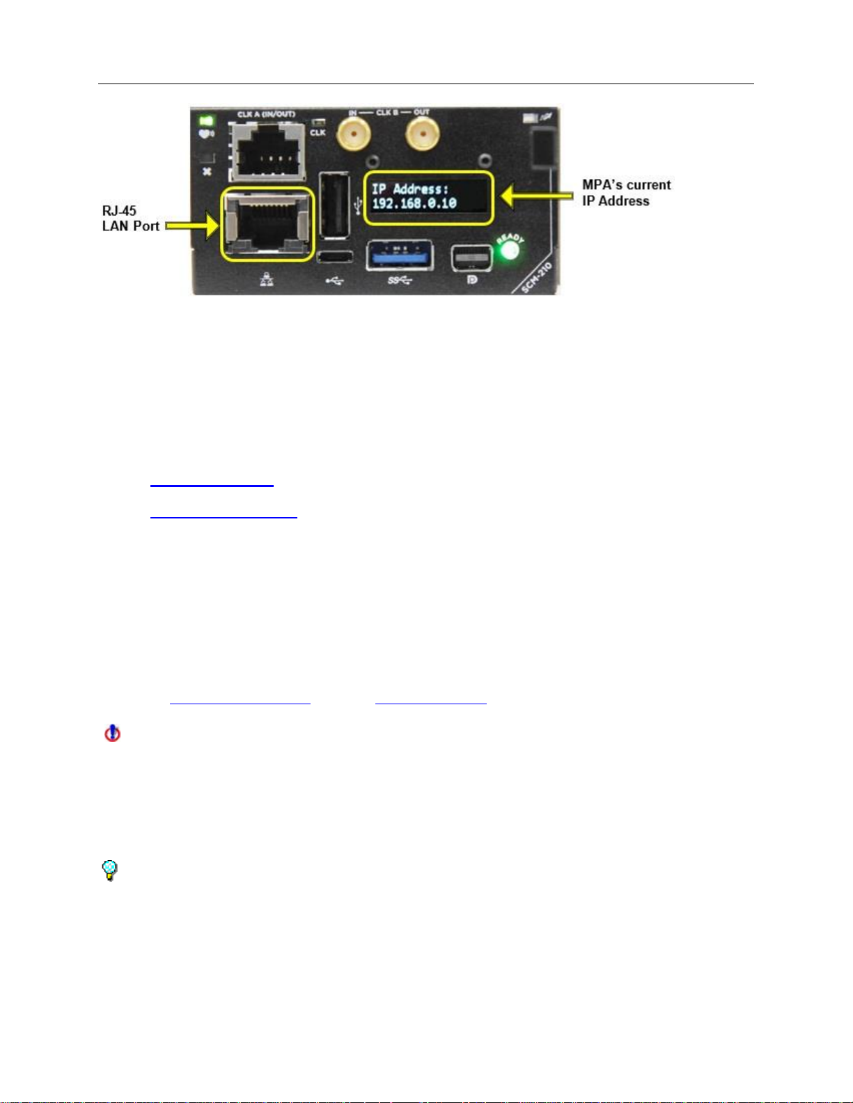
The MPA’s IP Address is configured on the SCM-210 controller card and is used for all
Ethernet communication to the MPA system, such as Remote GUI, VNC and SCPI, via
the RJ-45 LAN Port.
The MPA’s current IP Address is displayed on the OLED display screen.
19
Configuring the IP Address
MPA_e_manual_D07-00-129P_RevA00
• When the system is shipped from the factory, the SCM-210 controller card's
default IP Address is set to 192.168.0.10, with a Subnet Address of
255.255.255.0
The following methods can be used for changing the SCM-210’s IP Address:
• USB flash drive (preferred method)
• Remote GUI Client (must currently be connected by the Remote GUI client or
VNC)
AM4022 Processor and MCH Controller cards
This section describes how to configure the IP Address programmed on the MPA
system’s AM4022 processor and the MCH controller card combination.
For MPA system containing an SCM-210 controller card, please refer to the section
above for configuring the IP Address.
The MPA’s IP Address is configured on the AM4022 processor card and is used for all
Ethernet communication to the MPA system, such as Remote GUI, VNC and SCPI, via
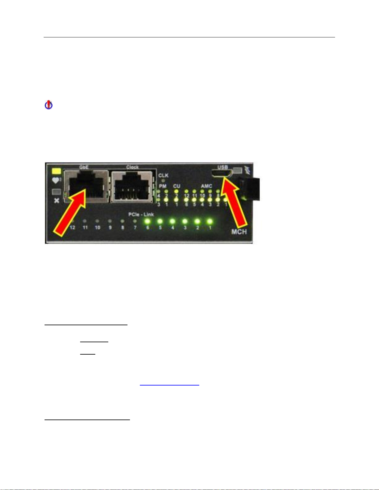
the MCH’s GbE port (as illustrated below).
Ethernet communication flows internally through the MCH’s GbE port to the AM4022
processor. The two RJ-45 connectors on the AM4022 processor are not used.
20

Getting Started
MPA_e_manual_D07-00-129P_RevA00
• When the system is shipped from the factory, the AM4022 processor’s default IP
Address is set to 192.168.0.10, with a Subnet Address of 255.255.255.0
• The MCH controller module’s default IP Address is set to 192.168.0.11, with a
Subnet Address of 255.255.255.0
o The MCH’s IP Address is only required if an External BITS/SETS chassis
clock is plugged into the RJ-48 Clock In/Out port
o See Changing the MCH module’s IP Address for changing the MCH
module’s IP Address
The following methods can be used for changing the AM4022’s IP Address:
• USB flash drive (preferred method)
• Remote GUI Client (must currently be connected by the Remote GUI client or
VNC)
Note: Regardless which card type or method you use to change the MPA's IP Address,
you will need to reboot the MPA in order for the setting to take effect.
For assistance with changing the IP Address, contact Customer Tech Support.
Changing the IP Address with a USB Flash Drive
The ability to change the MPA's IP Address with a USB flash drive (e.g., pen drive) is a
very simple and easy method of changing the IP Address, especially if you do not know
the MPA's current IP Address.
21
Configuring the IP Address
MPA_e_manual_D07-00-129P_RevA00
By attaching a USB flash drive containing the mpa_ipconfig configuration file to
either the SCM-210 or AM4022 Processor (depending on your unit's configuration), this
will automatically change the MPA’s IP Address to whatever IP Address is programmed
in the mpa_ipconfig file.
SCM-210 card (3x USB ports to choose from)
Software Requirements
• mpa_ipconfig (Editable text file)
This file is included in the USB drive that was shipped with the MPA system, also
it can be provided by contacting Customer Technical Support.
Hardware Requirements
• Standard USB flash drive (20KB of free space)
22

Getting Started
MPA_e_manual_D07-00-129P_RevA00
• PC with any text file editing software program (i.e., Notepad, Notepad++, or
Wordpad)
Wordpad tends to display the settings in an easier to read layout than
Notepad
• USB 2.0 Mini-A cable (only required for systems containing an AM4022
Processor)
(Two USB cables are shipped with the MPA systems containing the MCH card
and AM4022 Processor; a USB 2.0 Mini-A connector type for use with the
AM4022 Processor, and a USB 2.0 Micro-B connector type for use with the MCH
card)
Changing the Processor’s IP Address with USB Flash
1. The mpa_ipconfig file will need to be edited using any text-editor, and then
saved to a USB flash drive’s root directory.
a. The mpa_ipconfig file is a text file, but it does not have a file extension.
b. Do not rename the mpa_ipconfig file, nor give it a file extension.
c. If you downloaded the mpa_ipconfig.zip file our website or a customer
support email, then extract the mpa_ipconfig file out of the .zip file
before editing it.
2. To configure the MPA system for a Static IP Address:
a. Change the file’s IP Address, Subnet Mask, and Gateway to the
appropriate settings for your network.
b. By default, this file contains the following text, including a Carriage
Return and Line Feed control characters at the end of each line.
# MPA IP address configuration file.
IPADDR=192.168.0.10
NETMASK=255.255.255.0
GATEWAY=192.168.0.1
23
DNS1=8.8.8.8
DNS2=8.8.4.4

Configuring the IP Address
IP addresses 192.168.138.0 through 192.168.138.255 are reserved
and should not be used. A serious system conflict can occur if an IP
address in this range is assigned to the processor.
If you use an IP address in the range of 192.168.x.y (where x is not 138),
then you must set the Subnet Address to 255.255.255.0.
MPA_e_manual_D07-00-129P_RevA00
c. The default Primary and Secondary DNS Server addresses are
configured for 8.8.8.8 / 8.8.4.4, which are public DNS addresses created by
Google, and only need to be modified if being replaced with networkspecific DNS addresses.
3. To configure the MPA system to Obtain an IP Address from a DHCP server:
Note: Verify that an Ethernet cable linked to a DCHP server or router is
connected before setting the IP Address to DHCP.
a. Change the IP Address to the letters “DHCP”
# MPA IP address configuration file.
IPADDR=DHCP
b. When IPADDR=DHCP is used, all further Addresses in this file are
ignored.
4. Copy the reconfigured mpa_ipconfig file to the USB flash drive, if it is not
already on one.
5. Ensure the MPA system has been turned on for at least 4 to 5 minutes, and that
either the SCM-210's Ready LED is solid green or that the AM4022 Processor’s
status LED in the top left corner of the processor is solid green.
6. Close all open remote software connections to the MPA system, such as
Remote GUI, VNC, and/or SCPI.
7. Connect the configured USB flash drive to the MPA's processor card.
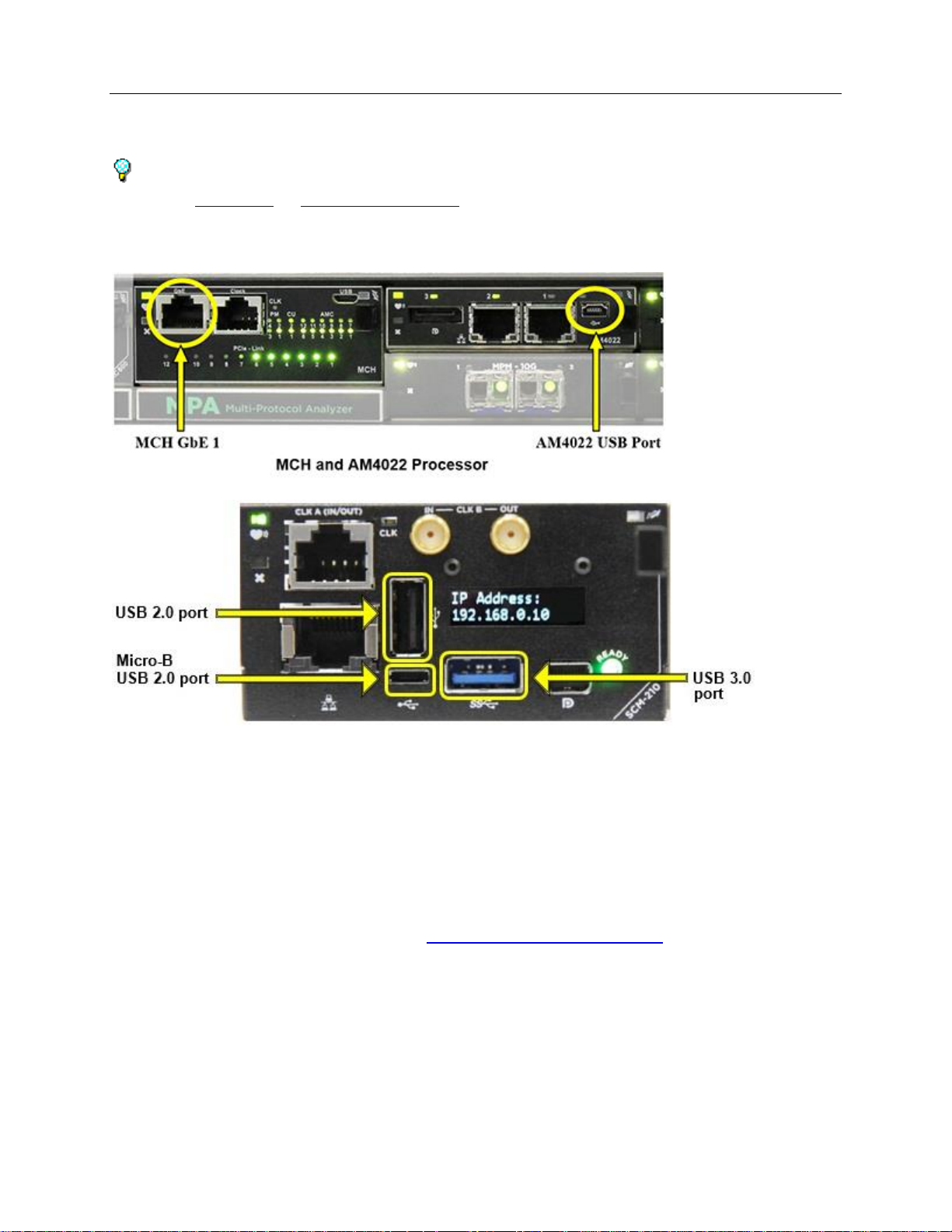
• For units with an AM4022 Processor, the USB flash drive connects to the
AM4022 processor's USB port using the USB Mini-A adaptor cable that
came with the system.
• For units with an SCM-210 card, the USB flash drive can be connected to
the most appropriate of the three USB ports available. The three USB
ports provided on the SCM-210 card include a standard USB 2.0 port, a
standard USB 3.0 port, and a Micro-B USB 2.0 port (which requires a USB
Micro-B adaptor cable).
24
Getting Started
MPA_e_manual_D07-00-129P_RevA00
• See images above for the location of the usb ports on both processor
cards.
8. Typically, within less than 30 seconds the file on the flash drive will automatically
reconfigure the IP Address and Reboot the MPA system.
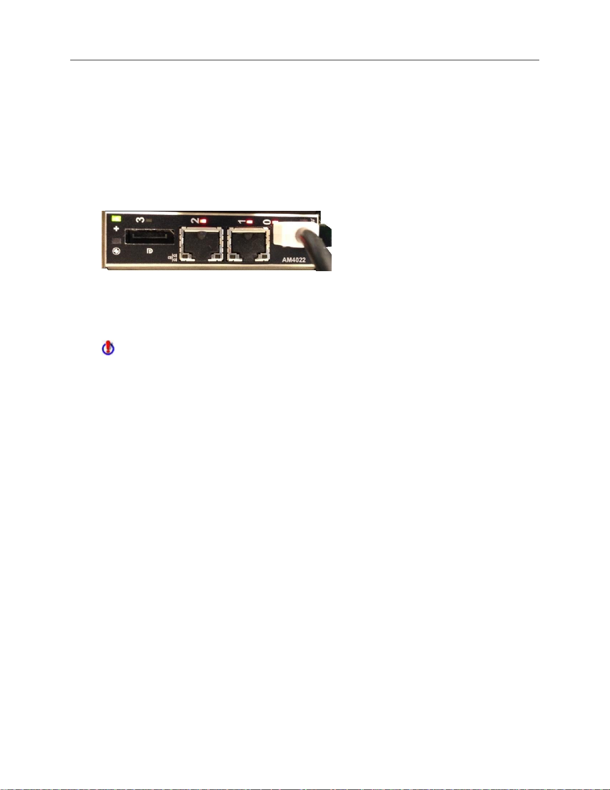
• For units with an AM4022 Processor, when the AM4022 Processor
reboots, you will see the LED’s above the Ethernet ports, the USB port
and Display port (labeled 0 – 3) briefly turn Red for a couple of seconds,
and back to Green (or off), as the processor reboots.
• For units with an SCM-210 card, the SCM-210’s OLED display screen will
go blank and the green READY LED will turn off, indicating that the
system is rebooting.
Note: If after 30 to 45 seconds the MPA system does not reboot, this could
indicate one of the following conditions:
• The IP Address configured in the mpa_ipconfig file is the same as that
already programmed on the MPA system
• The mpa_ipconfig file was possibly renamed, or given a file extension
• The mpa_ipconfig file was possibly saved to a sub-folder on the USB flash
drive, and not to the root directory
• The USB flash drive was not recognized the first time was inserted and
may need to unplugged and plug it back in again.
• The system may not have been fully booted prior to connecting the USB
flash drive, in which case wait a few minutes and try it again.
9. After the MPA begins the reboot process, disconnect the USB flash drive.
10. Wait for 4 to 5 minutes for the MPA system to finish booting up and verify that
you can now Ping and remotely connect to the processor’s new IP Address.
11. For units with an SCM-210 card, the new IP Address is displayed on the OLED
screen and the MPA is fully booted and operational again when the green
READY LED illuminates.
25

Configuring the IP Address
MPA_e_manual_D07-00-129P_RevA00
Changing the IP Address with the Remote GUI Client
The Remote Client software is a Windows PC based Graphical User Interface (GUI)
that remotely controls the MPA system, via the MPA’s IP Address.
If you are able to Ping the processor’s current IP Address, and are able to login to the
MPA via the Remote GUI client software, then you can change the processor’s IP
Address from the Remote GUI client.
You can also change the MPA’s IP Address from the remote desktop GUI via a VNC
connection, or from the local GUI via DisplayPort video monitor and USB mouse.
Software Requirements
• Remote Client software
• Current IP Address information for the MPA system
• New IP Address information for the MPA system
Hardware Requirements
• A Personal Computer with a 300-MHz Pentium processor or faster
• A standard 10/100/1000 Base-T Ethernet cable for connectivity between the PC
and the MPA system
• optional: Computer monitor with DisplayPort cable and a USB mouse connected
to the AM4022 or SCM-210
Changing the Processor’s IP Address from the Remote GUI
1. Establish a remote GUI connection to the MPA system, as described in DLI
Remote Client Application.
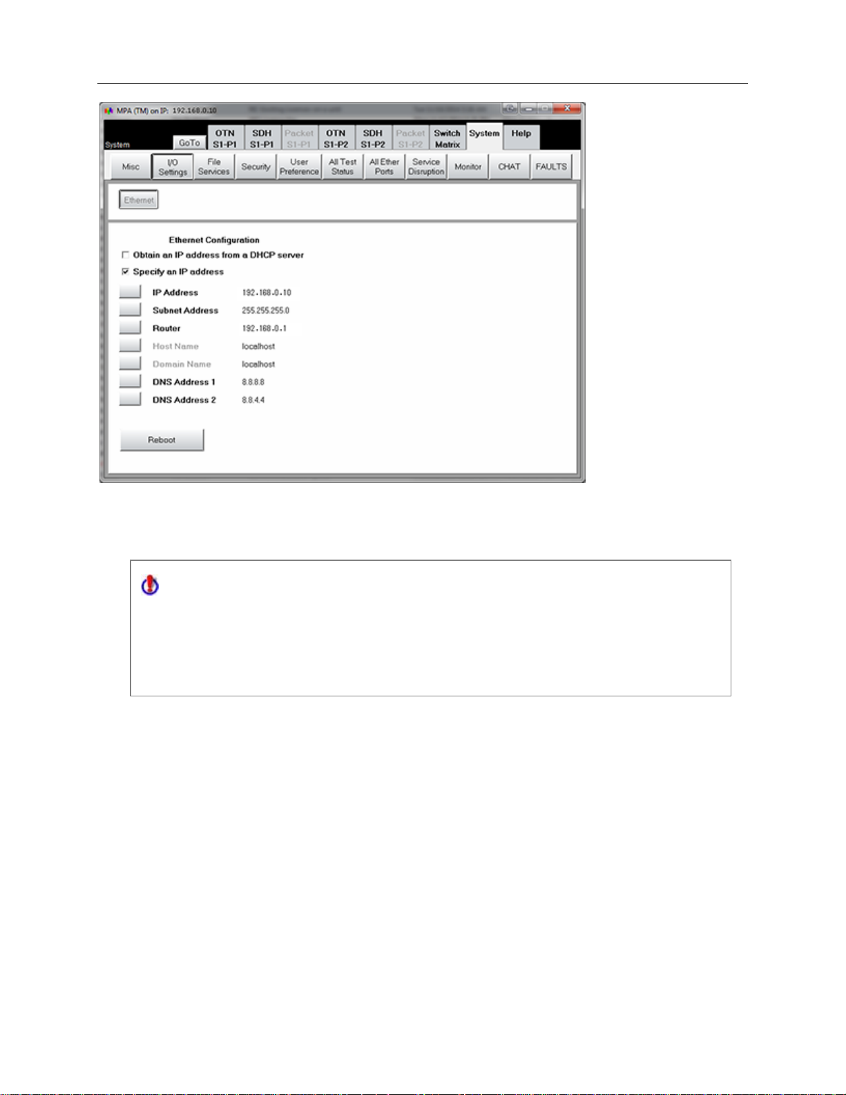
2. Select the System tab, and select the I/O Setting button.
3. The Ethernet Configuration screen appears.
4. Select Specify an IP address.
a. Only choose Obtain an IP Address from DHCP if know how to retrieve the new
IP Address automatically assigned from the DHCP server, or your MPA has an SCM210 card which displays the obtained IP address.
26
Getting Started
IP addresses 192.168.138.0 through 192.168.138.255 are reserved and
should not be used. A serious system conflict can occur if an IP address in
this range is assigned to the processor.
If you use an IP address in the range of 192.168.x.y (where x is not 138), then
you must set the Subnet Address to 255.255.255.0.
MPA_e_manual_D07-00-129P_RevA00
4. Enter the new IP Address, Subnet Address, and Router/Gateway Address to
the appropriate settings for your network.
6. The DNS Addresses should only be modified if specific DNS Addresses need to
be entered for your network, otherwise the default DNS Addresses do not need
to be changed.
a. By default, the DNS Address 1 (Primary DNS) is configured for 8.8.8.8,
and the DNS Address 2 (Secondary DNS) is configured for 8.8.4.4. These
are public DNS addresses established by Google, and only need to be
modified if being replacing with a network-specific addresses.
7. Reboot the unit using the Reboot button for the changes to take effect.
8. The current Remote GUI session will close.
9. Allow 4 to 5 minutes for the system to reboot, and for all of the internal software
applications to finish loading before connecting to the new IP Address.
27
Configuring the IP Address
MPA_e_manual_D07-00-129P_RevA00
Changing the MCH module’s IP Address
This procedure shows how to connect to the MicroTCA Carrier Hub (MCH) module, and
issue commands to configuring the MCH’s IP Address settings.
This procedure does not apply if your MPA unit has an SCM-210 card.
Communication to the MCH module can be via an Ethernet (Telnet) connection to the
MCH’s GbE Ethernet port (Option 1), or via a USB (Serial) connection to the MCH’s
micro-USB port (Option 2).
Note: After establishing a connection to the MCH card via either of the two options, then
you can View the MCH current IP Address, or Change the MCH IP Address.
Software Requirements
• For Ethernet, any Telnet client application software, such as PuTTY
• For USB, the nat_mch.inf driver file (included in USB flash drive, and available
upon request), and any Serial port terminal software, such as PuTTY
(PuTTY is included on the USB flash drive shipped with the MPA system, or can
be downloaded free from http://www.putty.org/)
Hardware Requirements
• A Personal Computer
28
Getting Started
MPA_e_manual_D07-00-129P_RevA00
• For Ethernet, a standard 10/100/1000BaseT RJ-45 Ethernet cable, connected
to a network or directly to a PC
• For USB, a USB 2.0 Micro-B cable (provided with system)
(Two USB cables are shipped with the new systems; a USB 2.0 Mini-A connector
type for use with the AMC Processor, and a USB 2.0 Micro-B connector type for
use with the MCH)
Option 1: Establish a connection to the MCH via Ethernet (Telnet):
1. To communicate with the MCH via Telnet, the MCH’s GbE current IP Address
must be known and responsive to Ping requests.
• The MCH’s default IP Address is 192.168.0.11 (for units built after of May of
2014)
• If the MCH’s current IP Address is unknown or does not respond to Ping
requests, then precede to the USB instructions
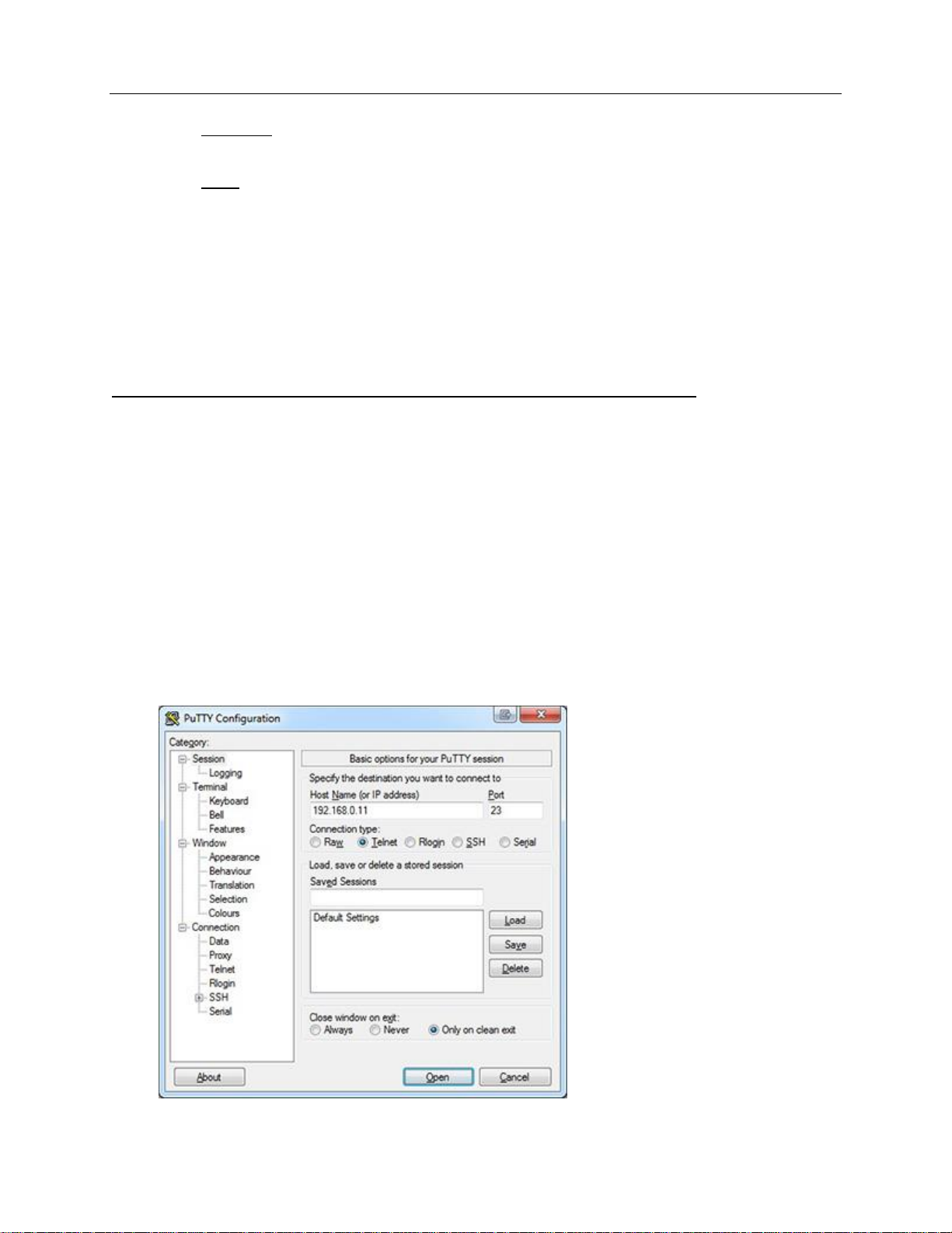
2. Launch the PuTTY utility, and select the Telnet Connection type (Port #23).
3. Enter the MCH’s current IP Address into the Host Name text box and click
Open.
29

Configuring the IP Address
MPA_e_manual_D07-00-129P_RevA00
4. A console window will appear stating Welcome to NAT-MCH, followed by a nat>
command prompt.
5. Verify the connection by pressing the Enter key to confirm that a second nat>
prompt appears.
Option 2: Establish a connection to the MCH via USB (Serial):
1. To communicate with the MCH via Serial, you will need a USB 2.0 Micro-B
cable, and the nat_mch.inf driver file (accessible from the Utilities folder in the
USB flash drive shipped with the MPA system or saved to a known location on
your PC).
a. Connect the PC to the MCH with the USB cable before installing the
driver.
b. If you have already installed the nat_mch.inf driver from a previous
connection, then skip this rest of this step.
c. If Windows displays an error stating the “Device driver software was not
successfully installed”, the nat_mch.inf driver will need to be manually
installed.
d. Open Device Manager and look for Unknown Device (with yellow
exclamation mark) listed under Ports or Other Devices.
e. Right-click on Unknown Device and select Update Diver Software.
f. Next, select “Browse my computer for driver software”, and browse to
the folder where the nat_mch.inf driver is located.
g. If a message appears stating “Windows can’t verify the publisher of
this driver software”, select “Install this driver software anyway”.
h. Once the driver has installed, Device Manage should show NAT-MCH
USB CDC Console listed under Ports, with a COM port number in
parenthesis.
i. Take note of the COM Port number assigned for this USB connection.
2. Launch the PuTTY utility.
30

Getting Started
MPA_e_manual_D07-00-129P_RevA00
3. Select Serial from the Connection branch listed under Category, to configure
the Serial port settings.
4. Enter the COM Port number that was automatically assigned for this USB
connection in Device Manage.
5. Configure the rest of the Serial Port settings as the following:
• Speed (Baud): 19200
• Data Bits: 8
• Stop Bits: 1
• Parity: None
• Flow Control: None
6. Click Open to establish the connection and wait for the console window to
appear.
7. Press the Enter key to display the nat> command prompt.
8. Verify the connection by pressing Enter again to confirm that a second nat>
prompt appears.
Viewing the MCH current IP Address (Telnet or Serial):
31

Configuring the IP Address
IP addresses 192.168.138.0 through 192.168.138.255 are reserved and
should not be used. A serious system conflict can occur if an IP address in
this range is assigned to the processor.
If you use an IP address in the range of 192.168.x.y (where x is not 138), then
you must set the Subnet Address to 255.255.255.0.
MPA_e_manual_D07-00-129P_RevA00
1. In order to view the MCH’s GbE port’s IP Address, first establish either a Telnet
or Serial connection to the MCH as described above, and verify the cursor
appears next to the nat> command prompt.
2. To view the currently configure IP Address settings, type ifconfig from the nat>
command prompt, and press Enter.
• The default GbE port’s IP Address is 192.168.0.11, with a Subnet Address of
255.255.255.0.
Changing the MCH IP Address (Telnet or Serial):
1. In order to change the MCH’s IP Address, first establish either a Telnet or Serial
connection to the MCH as described above, and verify the cursor appears next to
the nat> command prompt.
2. To change the IP Address settings, type ip from the nat> command prompt, and
press Enter.
3. The cursor appears after the current IP Address.
a. To change the IP Address, press the Backspace key to delete the
current Address (one digit at a time), then type the new Address followed
by Enter to proceed to the next setting.
4. The cursor then appears after the current IP Net Mask.
a. To change the Subnet Mask Address, press the Backspace key to
delete the current Address, then type the new Address followed by Enter
to proceed to the next setting.
5. The cursor then appears after the current IP Broadcast Addr.
a. To change the Broadcast Address, press the Backspace key to delete
the current Address, then type the new Address followed by Enter to
proceed to the next setting.
32

Getting Started
MPA_e_manual_D07-00-129P_RevA00
6. The cursor then appears after the current IP Gateway Addr.
a. To change the Gateway Address (Router Address), press the
Backspace key to delete the current Address, then type the new
Address followed by Enter to proceed to the next setting.
7. After the Gateway Address has been changed, a confirmation message appears
asking “Are you really sure?”
a. Press Y to Apply the new settings, followed by Enter.
b. Press N to Cancel the new settings, followed by Enter.
8. When the nat> command prompt reappears, the system will need to be turned
Off and back On.
a. Warning! Do not turn the chassis Power off without first deactivating MCH
and AMC cards.
9. Close the PuTTy connection as well as all remote software connections to the
MPA system such as the Remote Client GUI, VNC, SCPI or other software
connections to either the MCH or AMC Processor.
10. Follow the steps outlined in the Shutdown Procedure for turning the system’s
power Off.
a. After the power to the chassis is turned off, then push both of the
Unlock/Extraction handles back in and turn the power switch back On.
b. Wait about 4 to 5 minutes for the system to fully reboot, and then verify
that you can Ping or login into the MCH module, via the newly configure IP
Address settings.
33

Remote Client Application
If using Windows Vista or later, you may need configure Windows to run
the Remote GUI with Administrator permissions, even if you are already logged
in as an Administrator.
To do this Right-click on the DLI Remote Client icon and select Properties.
Then from the Compatibly tab, enable the “Run this program as
Administrator” option, and click OK.
MPA_e_manual_D07-00-129P_RevA00
Remote Client Application
Remote Client Application Overview
The Remote Client is a remote GUI (Graphical User Interface) application that allows
you to remotely connect to and control MPA products from a Windows based PC.
Before using the Remote Client:
• Verify the minimum software and hardware requirements.
• Verify that the Ethernet parameters have been entered into your test set.
• Verify that you have security access to the unit.
• Install the DLI Remote Client on to your PC.
To start the Remote Control Application:
1. Double-click the DLI Remote Client shortcut icon that appears on your PC's
desktop.
2. Enter the remote unit's IP address, and your User ID and Password.
The default User ID is Admin (case sensitive), and the default Password is
Admin1 (case sensitive)
3. Select OK.
• When attempting to connect to an MPA with the Remote Client
application for the first time, or for the first time after a software update,
the application tends to become unresponsive after the file transfer
process.
• If this happens, click Cancel or End Task on the Remote Client
application, then reconnect to the MPA a second time.
4. Once the connection is made, the remote unit's GUI appears. The title bar
contains the product name and connection method. Use your mouse to select
functions.
34

Getting Started
Important: Files that are created when using the Remote Control Application are
saved on your PC in the Remote Control’s compatibility directory.
If you want to keep these files, copy and save the following to a backup directory on
your PC that is not in the compatibility directory’s path:
• Any file with the .pdf, .set, .stat, .health, .evt, .aps, .perf, .rep, or .bmp
extension.
MPA_e_manual_D07-00-129P_RevA00
To automate the log on process, select Automating the Remote Control Icon
for more information.
5. If any problems are experience when installing or using the Remote Client, see
Troubleshooting Remote Client Application for solutions.
DLI Remote Client Requirements
Software
The minimum software requirements are:
• Windows XP, Vista, 7, 8, 10 or newer Windows operating systems.
• Microsoft Internet Explorer 5.0 or greater.
• TCP/IP Network Protocol
• Host domain and IP address information for LAN access.
Make sure that this information is entered into your unit. Refer to Ethernet Port
Configuration for more information.
Hardware
The minimum hardware requirements are:
• A personal computer with a 500-MHz Pentium processor or faster.
• 128 MB RAM (256 MB RAM recommended for optimum performance)
• 60 MB of free disk space
• An SVGA monitor with a minimum screen resolution of 800 x 600 pixels and 256
colors (1024 x 768 or higher recommended for optimum viewing), with the
Display Setting set to 100% DPI.
35

Remote Client Application
If you connect the unit directly to your PC, you will need the following:
• An Ethernet network interface card installed in your PC.
• Either a straight-through or a crossover Ethernet cable for connectivity
between the MPA and the PC's network interface card.
You need to install the Remote Client application upon your first use of the MPA
system and should upgrade to the latest Remote Client version when upgrading
your MPA to a major Feature Set change. For example, from Feature Set 7.0 to 8.0.
You must be logged into your Windows based PC/Laptop with Local Admin
Permissions, in order to install the Remote Client software application.
MPA_e_manual_D07-00-129P_RevA00
• USB flash drive (shipped with the MPA system), or web browser (if installing from
the DLI web site) for software installation.
• A standard 10/100/1000BaseT Ethernet cable for connectivity between the unit
and the network.
Remote Client Installation
The Remote Client software application is a Graphical User Interface (GUI) that
connects to the MPA via an Ethernet connection, from any Windows based PC, and
allows users to remotely control the MPA test modules.
The Remote Client software is supplied on the USB flash drive shipped with the MPA
system, and can also be downloaded from our website, or provided by email upon
request.
To install from the supplied USB drive:
1. Insert the USB drive into a standard USB port.
2. Open Windows Explorer and select the USB drive to display the contents and
open the Remote Client folder.
3. Double-click on SETUP.EXE to begin installing the Remote Client.
36

Getting Started
Important: Reports that were saved to the Compatibility folders, located in the
Remote Client application directory (for example, C:\Program
Files\DLI\RemoteClient\Compat700060032) will be deleted during the uninstall
process.
To save historical reports, copy and save data files with the following file extensions
to a folder located outside of the Remote Client application directory before
MPA_e_manual_D07-00-129P_RevA00
4. Select Next and follow the on-screen instructions to install the software into a
directory and create a program folder. The default directory is C:\Program
Files\DLI\RemoteClient.
5. When prompted for "How do you want to maintain the Remote GUI files on
your PC?", the default option is (A) Create Multiple Directories.
a. Use the (A) Create Multiple Directories default option for the fastest
execution when repeatedly connecting to the same test set, or to other
test sets with the same Feature Set version.
b. Select option (B) Create one GUI directory only if space is limited on
your PC’s hard disk drive, as this will require the Remote GUI files to
transfer from the test set to your PC every time you remotely connect to
the test set.
6. Select Finish to complete installation.
7. After the installation is complete, a DLI Remote Client shortcut icon appears on
the desktop. Open the application by double-clicking the DLI Remote Client
icon.
8. This completes the installation.
To install from the Internet or Email:
1. Contact Tech Support for a link to Remote Control installation file, or visit
www.veexinc.com to download the Remote Control installation file from our
website.
2. Double-click on the installation file to begin installing the Remote Client.
3. Refer to Step 4 above for the remaining installation instructions.
DLI Remote Client Removal
37

Remote Client Application
proceeding with the uninstall process.
• Any file with the .pdf, .set, .stat, .health, .evt, .aps, .perf, .rep, or .bmp
extension.
MPA_e_manual_D07-00-129P_RevA00
To remove the Remote Control Application
1. Close the DLI Remote Client application.
2. Click the Windows Start button and choose Settings.
3. Select Control Panel and choose Programs and Features.
4. Select DLI Remote Client and click the Uninstall/Change button.
5. Follow the on-screen instructions.
6. Open Windows Explorer and locate the Remote Client application directory. For
example, C:\Program Files\DLI\RemoteClient.
7. Delete the RemoteClient folder.
8. Install the new DLI Remote Client application, if upgrading to a newer remote
version.
Automating the DLI Remote Client Icon
The DLI Remote Client software is a graphical user interface (GUI) that allows you to
remotely control portable and rackmount products from a PC. An icon for the DLI
Remote Client software is created and placed on your desktop when the software is
installed.
Once installed, you can add a specific IP address, User ID, and Password parameters
to the icon to automate the login process.
1. From the desktop, right-click on the DLI Remote Client application icon.
2. Select Properties and choose the Shortcut tab.
3. Place the cursor at the end of the Target text box.
4. Press the space bar and then type:
ip=x.x.x.x, uid=y,pw=z
• x.x.x.x is the unit's IP address
• y is the user ID (case sensitive)
The default user ID is Admin
38

Getting Started
If an invalid parameter is entered, the automatic login will fail, and you must enter
the appropriate data.
MPA_e_manual_D07-00-129P_RevA00
• z is the password (case sensitive)
The default password is Admin1
• do not include any spaces between fields
Example: "C:\Program Files\DLI\RemoteClient\Galaxy.exe"
ip=10.1.8.21,uid=Admin,pw=Admin1
5. Click OK.
6. Now when you double click the DLI Remote Client application's icon, a
connection is automatically made, and the remote system's GUI appears.
Multiple DLI Remote Client applications can be running on the same PC at the same
time, each connected to the either same or different test sets.
Multiple DLI Remote Client icons can copied to your desktop, each with a
dedicated IP Address for connecting to multiple test sets.
1. Create a copy of the DLI Remote Client shortcut icon to your desktop.
2. Right-click on the copied DLI Remote Client application icon and select
Rename.
3. Rename the icon to the dedicated IP Address for the test set that this icon will
be configured to connect to, using the above procedure.
4. Follow the steps in the above procedure to configure this copy of the DLI
Remote Client icon to automatically connect to the test set's designated IP
Address.
5. Repeat this process for as many test sets as needed.
39

Remote Client Application
Symptom
Resolution
Remote Client will
not install
• Close all other running applications
• Reboot your PC/Laptop, and install the Remote Client
before opening any other software programs
"Transient" error
message when
attempting to connect
to the MPA
• Verify that you can Ping the MPA, and no other device
on your network has the same IP Address as the MPA
• Verify the network Ethernet cable is connected to the
MCH card's GbE port
• Verify you have Local Admin permissions on your
PC/Laptop
Initial remote file
transfer does not
complete
• Verify you have Local Admin permissions on your
PC/Laptop
• Temporarily disable any Firewall applications that
might be blocking the file transfer
Initial remote file
transfer completes,
but the GUI does not
launch
• Click the Cancel button, or End Task on the Remote
Client if required to close the application
• Launch the Remote Client again, and connect to the
unit a second time
• The remote file has already been transferred, so the
GUI should now launch as expected
MPA_e_manual_D07-00-129P_RevA00
Troubleshooting the Remote Client Application
This topic is intended to aid in resolving common Remote Client application problems.
For additional assistance, please contact Customer Service.
40

Getting Started
The GUI does not
look right, spaces
between tabs, etc
• The Remote Client requires the PC’s display setting’s
DPI to be set to 100%.
• Right-click on your desktop and select Display
Settings. Then adjust the setting labeled "Change the
size of text, apps and other items" to 100%. This
should resolve the look of the GUI, however you may
also need to adjust your screen resolution to
compensate for the change in font size
The GUI is open but
all of the settings are
disabled
• In order to change any of the settings, you will need to
click the padlock icon on the GUI and select Lock and
Exit. Refer to the Lock Icon for more information
The GUI is open but
only the System tab
and Help tab is
displayed
• Follow the proper Reboot instructions to reboot the
MPA
• Contact Customer Technical Support
MPA_e_manual_D07-00-129P_RevA00
VNC Connection
Virtual Network Computing (VNC) Connection As of Feature Set version 8.1.45 (and later), a VNC Server has been added to MPA
systems as another method of remotely controlling the system’s Graphical User
Interface (GUI) client software. In addition to the standard multi-user Windows based
Remote GUI client, the VNC Server on an MPA unit can also support simultaneous
VNC Viewer connections, allowing multiple users to remotely control a single MPA
system.
VNC works on a Viewer/Server model. Up to ten (10) VNC Viewers can simultaneously
be connected to the VNC Server running on the MPA, via the MPA’s IP Address
followed by a colon and a VNC Port number from 1 to 10, with one user per VNC Port.
Example: 192.168.0.10:1 to 192.168.0.10:10
The maximum number of simultaneous connections is subject to change pending
further evaluation.
41

VNC Connection
MPA_e_manual_D07-00-129P_RevA00
Advantages of using the VNC viewer to remotely control an MPA system:
• VNC viewers are supported on multiple OS platforms including; Windows, Mac
OS X, iOS, Android, and Linux, and are available for most portable devices such
as; Laptops, Tablets, and Smartphones.
• Remote Control operation without the need to install a dedicated Remote Client
application.
• No interference from Firewall software or other network restrictions.
• Since the Remote GUI client is displayed in full-screen mode within VNC viewers
that support the option to stretch and resize, the Remote GUI client can
effectively operate at any desirable viewing size.
• VNC viewer applications such as RealVNC (version 5.1 or newer),TightVNC,
UltraVNC, or whichever VNC viewer application is supported by your PC/device,
can typically be downloaded from the Internet for free.
VNC connection to MPA:
When the MPA is connected to the same network as your VNC equipped PC, or directly
connected to your PC’s Ethernet port, you can log into the MPA using the VNC viewer
to remotely control the user interface.
• Verify that the MPA’s IP Address has been configured, and you can Ping the IP
Address.
• Verify each concurrent VNC connection to the same MPA uses a different VNC
Port # (from 1 to 10). Example: 192.168.0.10:1 to 192.168.0.10:10
• Refer to VNC Viewer Configuration for the recommended configuration settings,
based on the VNC viewer application you are using.
• VNC viewers only require a login Password. A Username is not required.
• The default VNC Password for the MPA is Admin1.
• Refer to Multiple Remote VNC Desktops for multiple remote VNC desktop
connections.
VNC Viewer Configuration
For Optimal Performance, verify that your VNC viewer settings are configured for the following:
• Picture Quality should be set to the Highest setting available
• Scaling should be set to Automatic or Window Size
• Toolbar should be disabled
42

Getting Started
MPA_e_manual_D07-00-129P_RevA00
Below are recommended settings options for a few of the most popular VNC viewers.
Real VNC versions 4.1 and older do not support Preserve Aspect Ratio, and should not be
used.
Real VNC: version 5.1.x
1. Select Options.
2. From either the Basic tab or the Advanced Display tab, change/verify the following
options:
• Select: Scale to Window Size
• Enable (check): Preserve Aspect Ratio
• Disable (uncheck): Enable Toolbar
3. Enter the MPA’s IP Address in the VNC Server field, followed by colon (:) and the VNC
Port #.
• Verify the VNC Port # (from 1 to 10) being entered is not being used by another
• Example:
43
user.

VNC Connection
MPA_e_manual_D07-00-129P_RevA00
4. Click on Connect.
5. If an Unencrypted Connection message appears select (check) Don’t warn me about
this again and click Continue.
6. Enter the MPA’s VNC Password and click OK.
• The default VNC Password for the MPA is Admin1.
Real VNC: version 6.1.x
1. Select New Connection from the File menu.
2. From the Options tab, select the following options:
• Set the Picture Quality to High
• Disable (uncheck): View-only
• Set the Scaling to Automatic
• Enable (check): Preserve Aspect Ratio
• Enable (check): Pass Media Keys …
• Enable (check): Pass Special Keys …
3. From the Expert tab, scroll down and highlight the Enable Toolbar parameter.
• Set the Value to False.
4. Enter the MPA’s IP Address in to the VNC Server field on the General tab, followed by
colon (:) and the VNC Port #.
44

Getting Started
MPA_e_manual_D07-00-129P_RevA00
• Verify the VNC Port # (from 1 to 10) being entered is not being used by another
user.
• Example:
5. Leave the Name section empty for shortcut icon to be labeled as the IP Address and
Port #, or enter a “Friendly Identifier” name, associated with this MPA and Port #.
6. Click OK to add the newly created VNC shortcut icon to the VNC viewer’s desktop
section.
7. Double-click the VNC shortcut icon to connect to the MPA.
8. If an Unencrypted Connection message appears select (check) Don’t warn me about
this again and click Continue.
9. Enter the MPA’s VNC Password and click OK.
• The default VNC Password for the MPA is Admin1.
TightVNC: version 2.8.x
1. Select Options from the main menu.
• Disable (uncheck): 256 colors in the Format and Encodings section, if enabled.
• Set the Scale By to Auto in the Display section.
• Select Track Remote Cursor Locally in the Mouse Cursor section.
• Select Do Not Show in the Local Cursor Shape section.
• Leave the remaining options as set by default.
45

VNC Connection
MPA_e_manual_D07-00-129P_RevA00
2. Select Configure from the main menu.
• Disable (uncheck): Show Toolbars by Default, in the User Interface section.
• Leave the remaining options as set by default.
3. From the Main Menu, enter the MPA’s IP Address in the Remote Host field, followed by
colon (:) and the VNC Port #.
• Verify the VNC Port # (from 1 to 10) being entered is not being used by another
user.
• Example:
4. Click on Connect.
5. Enter the MPA’s VNC Password and click OK.
• The default VNC Password for the MPA is Admin1.
Multiple Remote VNC Desktops
In addition to the standard multi-user Windows based Remote GUI client, the VNC
Server on an MPA unit can also support simultaneous VNC Viewer connections,
allowing multiple users to remotely control a single MPA system from any Operating
System.
46

Getting Started
MPA_e_manual_D07-00-129P_RevA00
When connecting to the MPA with VNC, each VNC Port # (1 to 10) has its own
dedicated desktop. Example: 192.168.0.10:1 to 192.168.0.10:10
Each of the ten VNC remote desktops include a shortcut icon for the Remote Client
software, which can be launched and run independently of the other VNC desktops, as
well as a copy of this MPA User's Manual.
This multiple remote VNC desktop approach allows up to ten concurrent, and
completely independent, remote logins to a single MPA unit via VNC.
Remote GUI Login
1. Refer to Virtual Network Computing (VNC) Connection to establish a VNC
connection to the MPA unit.
2. From the VNC desktop, double-click the MPA REMOTE GUI icon to launch the
Remote Client.
• Unlike the VNC connection, the Remote Client connection requires both a
User ID and a Password.
3. Enter the GUI’s User ID and Password and click OK to login.
• Any User ID created on that MPA can also be used to login to the Remote
GUI.
• The default User ID is Admin and the default Password is Admin1.
• See the MPA User’s Manual for details on Adding a New User.
4. The GUI will appear, filling the VNC viewer window.
47

VNC Connection
MPA_e_manual_D07-00-129P_RevA00
Resizing the Remote GUI
Notice that the initial size of the VNC window may have reset to a default size upon
launching the Remote GUI application.
Since the Remote GUI runs in full-screen mode within the VNC viewer window, users
can now resize the GUI to any desired viewing size by grabbing and dragging any of the
four corners, stretching the size of the VNC window and making the GUI appear
proportionately larger or smaller.
48

Getting Started
MPA_e_manual_D07-00-129P_RevA00
Closing the Remote GUI
Just closing the VNC connection to the MPA does not automatically terminate the
Remote GUI application running on the VNC’s remote desktop.
Because the Remote GUI runs on a remote desktop, it will continue to run even when
you close the VNC connection used to view the remote desktop, possibly resulting in
valuable resources being needlessly unused which instead could be used by other
users.
When you are ready to close your Remote GUI session to the MPA, you should first
close the Remote GUI application by logging out of the application, and then close the
VNC viewer.
To Logout of the MPA, select the Shut Down button from the bottom right corner of the
GUI, then choose Logout from the shutdown menu.
• Logout closes your Remote GUI session without affecting
other users.
• The Shutdown and Reboot options will also close your
Remote GUI session, before shutting down or rebooting the
MPA’s Processor.
• You will need to confirm your selection from an “Are you
sure?” prompt.
Shutdown and Reboot
When logged in to the GUI with Admin permissions, then the Shutdown and Reboot
options are always available, even another Remote user has one or more ports Locked
by another user.
• The “Are you sure?” prompt for Shutdown and Reboot will contain a note
stating this action will affect all ports when one or more ports are locked by
other users, as a reminder that this action will also affect the other users
connected to this unit.
49

VNC Connection
MPA_e_manual_D07-00-129P_RevA00
When logged in to the GUI with Read/Write permissions, then the Shutdown and
Reboot options are not available if one or more ports are locked by other remote users.
• Users with Read/Write permissions will only have the Logout option if one or
more ports are locked by other remote users.
Retrieving Saved Reports
Test Reports, Screen Captures, Setup Configuration Settings and other files are
saved using the Report button from the Remote GUI within a VNC connection.
These files are all saved to the default FTP folder on the MPA.
• Screen Captures and reports that are automatically generated from Action After
Duration timed-tests are saved to the [etc] sub folder.
Users can then easily transfer their saved files from the MPA to their local PC, using
any FTP client program.
50

Getting Started
MPA_e_manual_D07-00-129P_RevA00
To retrieve saved files with any FTP client program, such as FileZilla, CuteFTP or WSFTP, enter the MPA’s IP Address followed by the same Username and Password that
was used to login to the Remote GUI.
• If a TCP Port # is required, the default Port # for FTP is 21.
• The default FTP Username is Admin and the default Password is Admin1.
• However, any User Name created on that MPA can also be used to login with
FTP.
See Add a New User for details on creating new login user accounts.
51

Troubleshooting:
Issue:
Resolution:
Unable to connect to
VNC server
• Verify the MPA's IP Address is valid, and that there are no IP
Address conflicts on the network.
• Verify the software version on the MPA is Feature Set 8.1.45, or
later
• Verify the MPA unit is fully functional and can either be logged
into with the Remote GUI application software, or operational as a
stand-alone unit using an external monitor connected to the
DisplayPort and a USB mouse and keyboard connected to the
USB port.
Resizing the VNC
window does not
automatically resize
the GUI
• The VNC's Preserve Aspect Ratio setting is disabled.
• The VNC viewer does not support Preserve Aspect Ratio,
and needs to be upgrade to a newer version.
Password
Authentication Failed
• The wrong password is being entered.
• If the “root” user authentication password has been changed or
forgotten, you can enter a new VNC Authentication Password
from the VNC Config window in the Security settings screen.
Low Color Resolution
• From the VNC viewer's options screen, change the Color settings
to the highest setting available (or Full Color resolution).
MPA_e_manual_D07-00-129P_RevA00
Common Function Buttons
Common Function Buttons
Common Function Buttons
The bottom of the touch screen contains task-oriented buttons. These buttons do not
appear when using the System or Help tabs. Additionally, buttons that do not pertain to
a protocol will not appear when that protocol tab is selected.
The Common Function Buttons include:
• Error Insert
52

Getting Started
The LEDs will continue to update and indicate current activity.
MPA_e_manual_D07-00-129P_RevA00
• Stop
• Restart
• Presets
• Report
• Test Setup
• Clear History
• Lock Screen
• Shut Down
Error Insert
The Error Insert common function button is used to injects single errors into the
transmitted protocol processor signal:
If no error types are specified for the Error to Insert setting in the Transmit > Error /
Alarm screen, then a Select Error to Insert menu will appear when the Error Insert
button is first pressed, allowing the user to specify which error type to insert.
The Error Insert button then causes single error insertions of the selected Error Type
each time the button is pressed.
Stopping a Test
The Stop common function button stops the reporting of received data and takes a
snapshot of error, alarm, and event activity.
When the Stop button is selected, the following occurs:
• All statistics logged and reported by the Performance Monitoring function stop.
• All alarm, error, and event statistics logged and reported by the Results function
stop.
• All elapsed time and duration counters stop.
To stop a test:
53

Common Function Buttons
MPA_e_manual_D07-00-129P_RevA00
• Select the Stop common function button located at the bottom of the touch
screen.
To restart test activity and statistic reporting, select the Restart button.
Restarting a Test The Restart common function button is used to initiate the following test activities:
• Clears and resets error, alarm, and event activity counters, statistics, and LEDs
for the current protocol processor.
• Restarts monitoring for error, alarm, or event activity that was stopped using the
Stop button.
• Elapsed Time counter resets to 000 Days, 00 Hours, 00 Minutes, and 00
Seconds, and then begins to increment after the Restart finishes.
To restart a test or reset statistics:
• Select the Restart common function button located at the bottom of the touch
screen. Configured testing on the current protocol processor is restarted.
Presets Function
The Presets function provides a quick and convenient way to set up the system for
operation. Using Presets involves selecting a starting protocol and its interface, and
then making an internal connection to another protocol, such as Add/Dropping from
OTN to a lower SONET/SDH mapping.
To set up a connection using the Presets function:
1. Select Presets from the Common Function Buttons row.
2. Select Interface. All line interfaces available for your unit appear.
3. Select an interface as a starting point.
4. Select Configuration. The protocols available for the selected interface appear.
5. Select a protocol to connect to the interface. If required, select the
Configuration button again to create additional connections.
54

Getting Started
If you make a mistake while creating connections, simply select Interface and
reenter the interface value. This action erases any previously entered interface or
configuration values.
MPA_e_manual_D07-00-129P_RevA00
6. Select Apply. The unit takes a few moments to apply the new protocol
connections.
To disengage the configured protocol connections:
• Select All to Tx/Rx. This globally disconnects any internal connections between
multiple protocol processors. A protocol processor will now expect to receive a
signal using its line interface.
Saving and Printing Statistics and Settings Reports
The MPA test set provides the option to Print or Save several Report types. To save or
print test reports:
1. Select from the Common Function Buttons row at the bottom of the
screen. The Report Setup dialog box appears.
55

Common Function Buttons
Settings
Reports the Stream Settings for the selected Port.
Statistics
Reports all Steam Tx/Rx Packet counts, Errors, and Alarms.
Events
Reports a summary of Events, such as alarm and error activity.
APS
Reports the K1/K2 byte sequences results summary.
Performance
Reports the Performance Monitoring results.
Capture
Reports the results from an overhead byte capture test
Serv Disrupt
Reports Service Disruption statistics.
RTD
Reports the Round Trip Delay measurements.
RFC Thru
Put
Reports the Throughput test settings and a summary of the test
results for each packet size (passing rate, transmitted and received
packets, minimum/maximum/average latency).
RFC Frame
Loss
Reports the Frame Loss test settings and a summary of the test
results for each packet size (passing rate, transmitted and received
packets, minimum/maximum/average latency).
RFC B2B
Burst
Reports the Back to Back Burst test settings and a summary of the
test results for each packet size (Max Possible Number of Frames,
and Average Observed B2B Frames).
RFC
Combined
Combines the RFC Thru Put, RFC Frame Loss and RFC B2B Burst
reports into one report.
Y1564
Settings
Reports the Y.1564 Settings including the Ramp Steps and enabled
Service Stream settings.
Y1564 Ramp
Reports the Y.1564 Configuration Ramp test summary for each
Service Stream tested (Step, CIR%, Frame Loss%, Max Jitter, Max
MPA_e_manual_D07-00-129P_RevA00
2. Choose the Report type(s) to be printed or saved.
The most common report is the Statistics report, which contains a complete list of
error and alarm statistic information as well as other counts that pertain to the test
performed.
Multiple reports can be combined into one file by selecting more than one report type.
Some of the reports listed below are only available for specific protocol processors.
56

Getting Started
Latency, Avg-RX%, Status).
Y1564 Perf
Reports the Y.1564 Performance test summary for each Service
Stream tested (Avg-RX%, , Loss%, Min/Max/Avg/Curr Jitter,
Min/Max/Avg/Curr Latency, Sequence Error Stats, Loss Error Stats,
Status).
Y1564
Combined
Combines the Y.1564 Settings, Ramp, and Performance reports into
one report.
Printer
The selected report is sent to your PC's default printer.
Text File
The selected report is saved as an ASCII text file, with a .txt file
extension.
Delimited
The selected Settings or Statistics report is save as a text file, using
Comma Delimited (CSV) file format, with a .csv file extension.
PDF Printer
The selected report is sent to your PC's default printer. The format of
the report is similar to the PDF file which allows a User Image file
(such as your company’s logo) to be printed at the top of the report.
PDF File
The selected report is saved as a PDF file, and this format allows a
User Image file (such as your company’s logo) to be saved at the top
of the report file, with a .pdf file extension.
MPA_e_manual_D07-00-129P_RevA00
3. Select the Destination Printer or File type. The following report Destinations are
available:
4. You can add a User Comment, that will appear at the beginning of the report.
This is useful if you want to include specific note about the test in the report.
Click the Input button to enter any User Comments that you wish to appear in
the printed or saved report file, using the Key board screen that appears.
Press the Clear button to clear the User Comments.
5. When printing a report to PDF Printer or PDF File, you can include a User
Image file (such as your company’s logo image) to be printed/saved to the top of
the report file.
57

Common Function Buttons
MPA_e_manual_D07-00-129P_RevA00
Supported image files formats include: .JPG, .PNG, .GIF and .BMP file
extensions.
Click the User Image File button to open a File Browser window.
When printing/saving the report using the DLI Remote Client GUI, then the
image file must be copied to the C:\Program
Files\DLI\RemoteClient\Compat<feature set> folder before selecting Print Report.
For the best appearance quality, the image file should have a width to
height ratio of 5:1, with a maximum dimension size of 750px by 150px.
6. Select OK to begin Printing or Saving the specified report.
7. If printing to a Text File, Delimited, or PDF File, then the File Browser dialog box
opens, allowing you enter a report file name.
Select File Name, and using the Key board screen that appears, enter the File
Name of your choosing.
Enter a file name and select OK.
File names cannot include special characters or any spaces.
The File Extension will automatically be entered, based on the report type
selected. PDF files will also include a .PDF extension.
Most Reports will automatically be assigned a file name consisting of (<type of
report>_<mmddyyyy>_<hhmmss>.<file extension>)
Ex. set_03092017_155039.pdf
8. For instructions on viewing saved report files see Printing or Viewing Saved
Files.
Test Setup Button
This menu provides the options to either Save the current Test Set configuration and
settings, or to Restore either a previously saved settings file, or Restore the Test Set to
Factory Defaults for a specific Protocol Mode, or just change the current Protocol
Mode.
58

Getting Started
MPA_e_manual_D07-00-129P_RevA00
• Save This Test Set to File: Saves the current Test Set configuration and
settings.
• Restore this Test Set from File: Restores the Test Set's settings from a
previously saved settings configuration file.
• Set the Protocol Mode: Changes the unit's Protocol settings. If this option is
selected, the processor's protocol mode is changed (for example, from SONET to
SDH).
• Factory Defaults: Restores the Test Set to Factory Defaults for a specific
Protocol Mode
Saving a Customized Settings Configuration
Saves a customized configuration for all protocol processors' Transmit or Receive
settings, for the selected Test Unit. For example, when a customized settings
configuration is saved while in a particular protocol processor mode (for example, SDH),
the settings currently configured for other protocol processors (for example, OTN, etc.)
will also be saved with that setting configuration.
To save a configuration:
1. Create a test configuration using the Transmit and Receive Settings screens.
2. Once you are done, select Test Setup from the Common Function Buttons.
3. Select Save This Test Set to File from the menu. The File Browser window
appears.
4. Press File Name. The Enter User String keyboard appears.
5. Enter a settings file name and select Enter when done.
• Do not include the Space character in any file name
• Do not type a file extension; the .SET file extension will automatically be
added to the filename.
6. Select Drive, if you wish to save the file to a different Drive letter, such as a USB
thumb drive.
7. Double click on an existing directory, or click New Dir and create a new directory,
if you do not wish to save the file in the default directory.
8. Select OK to save the settings file.
59

Common Function Buttons
Protocol Mode
SONET
Protocol Mode
SDH
These options appear if your unit contains one or more
SONET/SDH board, but no PDH board
MPA_e_manual_D07-00-129P_RevA00
Restoring a Settings Configuration or Factory Defaults
This function allows you to perform the following actions:
• Change the Protocol Mode: Changes the unit's Protocol settings. If this option
is selected, the processor's protocol mode is changed (for example, from SONET
to SDH).
• Restore Settings to Factory Defaults: Restores the unit's factory set default
settings. If this option is selected, the processor's default settings are
immediately restored for the selected protocol mode.
• Restore Settings from Saved File: Recalls any saved configurations for a
protocol processor's Receive or Transmit settings.
Change the Protocol Mode:
1. Select Test Setup from the Common Function Buttons.
2. Select the Set Protocol Mode button.
3. The following menu options appear:
4. Select the desired protocol mode. The protocol tabs and settings will be updated
to reflect the selected mode, but this does not revert the settings back to their
factory assigned default values.
Restore settings to Factory Defaults:
1. Select Test Setup from the Common Function Buttons.
2. Select the Factory Defaults button.
3. The following menu options appear:
60

Getting Started
Restore To Factory
Default SONET
Restore To Factory
Default SDH
These options appear if your unit contains one or more
SONET/SDH board, but no PDH board
MPA_e_manual_D07-00-129P_RevA00
4. Select the desired protocol mode. The protocol tabs and settings will be updated
to reflect the selected mode, and all of the protocol settings will revert back to
their factory assigned default values.
To restore from a settings configuration file:
1. Select Test Setup from the Common Function Buttons.
2. Select the Restore the Test Set from File button.
3. The File Browser window appears.
4. If the settings file was save to a USB thumb drive, or to another drive letter, the
select Drive and choose the drive letter where the file is located
5. From the File list, select the name of the settings configuration to be restored.
6. Select OK to restore from the settings file.
Clearing LED History and Resetting Results
The unit uses the following functions to log event, alarm, and error activity monitored on
the incoming signal:
• LEDs as displayed in the Quick Status LEDs area and the Large LEDs tab
• Every LED has a text label (Status Indicator) which will turn Red when the
specific occurs, and remain Red after the event clears
• The many Results windows display the number of events counted and/or the
total time the events occurred for
To only clear LEDs and Status Indicator history:
61
Common Function Buttons
The Clear History button does not reset error counts, alarm counts, or data
that appear in graphs. To clear this data, use the Restart button.
MPA_e_manual_D07-00-129P_RevA00
• Select the Clear History common function button that appears at the bottom of
the touch screen
• The LEDs' recorded history clears (Status Indicator)
• Refer to Using LEDs for LED color descriptions
To restart a test or reset statistics:
• Select the Restart common function button that appears at the bottom of the
touch screen.
• Resets errors, alarms, and event activity counters, statistics back to 0 for the
current protocol processor.
• Restarts errors, alarms, and event activity that may be stopped from using the
Stop button.
• The LEDs' recorded history clears (Status Indicator)
• The Elapsed Time reset to zero seconds, and begins counting over again.
Locking/Unlocking Screen Access
The Remote Client Application screen can be disabled to prevent user access by
others. This function requires a user ID and password to lock and unlock the screen.
When unlocking the screen, the unit will only accept the last user ID and password
entered, or the unit's original user ID and password.
To lock the screen:
1. Select Lock Screen from the common function buttons. The Lock Screen dialog
box appears.
2. Enter the User ID required to unlock the screen.
Press to open an on-screen keyboard, or use a mouse and keyboard to
enter the User ID.
62

Getting Started
If the unit is locked because critical testing is in progress, select the Unlock
button and enter the User ID and Password again. Select OK.
The unit will only accept the last User ID and Password entered, or the current
user’s login User ID and Password. An error message appears if an invalid ID or
Password in entered.
MPA_e_manual_D07-00-129P_RevA00
3. Enter the Password required to unlock the screen.
Press to open an on-screen keyboard, or use a mouse and keyboard to
enter the Password.
The Password is masked with asterisks, so it will not be displayed on the screen.
4. Select OK. The Locked Unit dialog box appears in front of the user interface.
This dialog box remains on the screen, preventing access to the user interface,
until the screen is unlocked.
To unlock the screen:
1. Select the Unlock button from the Locked Unit dialog box. The Unlock Login
dialog box appears.
2. Enter your User ID.
Press to open an on-screen keyboard, or use a mouse and keyboard to
enter the User ID.
3. Enter your Password.
Press to open an on-screen keyboard, or use a mouse and keyboard to
enter the Password.
The Password is masked with asterisks, so it will not be displayed on the screen.
4. Select OK.
Shutdown or Reboot the Processor from the GUI
The procedure described below allows the system to write unsaved data to the disk
before you shutdown the test set. This task is performed by selecting the Shut Down
common function button on any Protocol Processor tab.
63

Common Function Buttons
MPA_e_manual_D07-00-129P_RevA00
To shut down the Processor from a Protocol Processor tab:
1. Select the Shut Down from the common function button row.
2. Select on of the two options
• Shutdown
• Reboot
Shutdown
1. When Shutdown is selected, a Shutdown window appears giving you the option
to select OK or Cancel.
2. Selecting OK will begin the shutdown process, which may take up to 30 seconds
or so.
3. The Remote GUI will automatically disconnect from the MPA unit, and close.
4. If your MPA unit has an AM4022 Processor and MCH card combination, then at
this point the blue hot-swap LED on the AM4022 Processor will flash on/off in
short blinks while the processor is shutting down. Wait for the hot-swap LED to
turn solid blue before proceeding.
a. If your MPA unit has an SCM-210 card, then skip to step 6.
5. Pull out the Unlock/Extraction handle (to the first stop position) on the MCH,
and wait for its hot-swap LED to turn solid blue.
6. If your MPA unit has an SCM-210 card, then at this point the OLED display
screen will go blank and the green READY LED will turn off as the SCM-210
card's processor shuts down.
a. If your MPA unit has the AM4022 Processor and MCH card combination,
then skip to step 8.
64

Getting Started
MPA_e_manual_D07-00-129P_RevA00
7. Pull out the Unlock/Extraction handle (to the first stop position) on the SCM210 card, and wait for its hot-swap LED to turn solid blue.
6. Proceed with the rest of the MPA Shutdown Procedure.
Reboot
1. When Reboot is selected, a Reboot the Unit window appears giving you the
option to select OK or Cancel.
2. Selecting OK will begin the Reboot process, which may take several minutes to
complete.
3. The Remote GUI will automatically disconnect from the MPA unit, and close.
4. After waiting about 5 minutes or so, the Remote Client software should be able to
reconnect with the rebooted MPA system.
Common Tasks
Common Tasks Overview
This section lists common tasks that are performed the same for each protocol
processor mode. For tasks that are protocol processor specific, refer to the appropriate
protocol processor section.
65

Common Tasks
MPA_e_manual_D07-00-129P_RevA00
Please use the Contents tab and window (left side of the screen) to select, open, and
view the information in this section.
• Software Upgrade
• Timed Licenses
• MPA Shutdown Procedure
• Fiber Optic Cleaning Procedure
Software Upgrade
The following procedure is for upgrading an MPA system which already contains
Feature Set 7.5.35 or later, to a newer Feature Set version.
Note: If the current software version on your system is less than Feature Set 7.5.35,
then contact Customer Technical Support for assistance with upgrading older software
versions.
See the System Tab's About This Product screen for the MPA's current Feature Set
number.
Software Upgrade Requirements
• Verify you can Ping the MPA processor’s current IP Address
o See instructions on Configuring the IP Address (if needed)
• PC with Windows XP, or newer Windows operating system, and web-browsing
software (e.g., Internet Explorer, Chrome, Firefox, etc.)
• Software release tca.X.Y.ZZ.tgz (where X.Y.ZZ is the actual software version. If
the new Feature Set version is 8.1.89, the software upgrade file will be named
tca.8.1.89.tgz)
o The latest tca.X.Y.ZZ.tgz release file can be downloaded from
www.veexinc.com, or by contacting Customer Technical Support
o Do not extract the contents from this compressed file.
Software Upgrade Procedure (Current Feature Set ≥ 8.0.51)
66

Getting Started
MPA_e_manual_D07-00-129P_RevA00
1. Before updating the MPA system, close all open Remote GUI, VNC and/or SCPI
connections to the MPA system.
2. Open a web-browser, and enter the MPA processor’s IP Address in the URL
field, and then press Enter to connect. 1
3. The System Software Update screen appears as soon as you connect to the
MPA system.
4. Click the Choose File button. 2
5. Browse to the location where the tca.X.Y.ZZ.tgz was saved, and select the .tgz
file.
6. Click the Upload and Update Software button to begin the software upgrade. 3
7. After pressing the Upload and Update Software button the .tgz file will upload
to the MPA system, which can take several seconds, followed by a System
Software Update screen stating “The software update process has started”.
Warning! Do not turn the MPA’s Power Off, or connect to the MPA system during
this time period.
8. The web browser can be closed out after the System Software Update screen
is displayed, as the browser will not provide any additional feedback or
functionality during the rest of the software upgrade process.
9. The MPA system will automatically reboot as part of the upgrade process, which
may take between 5 to 15 minutes depending on the unit configuration, after
which you can remotely connect to it again.
10. After waiting the appropriate amount of time, reconnect to the system with the
VCN or the Remote Client GUI and verify the MPA is now configured with the
Feature Set version from the System Tab's About This Product screen.
67

Common Tasks
MPA_e_manual_D07-00-129P_RevA00
• When attempting to connect to an MPA with the Remote Client
application for the first time after a software update, the application tends
to become unresponsive after the file transfer process.
• If this happens, click Cancel or End Task on the Remote Client
application, then reconnect to the MPA a second time.
Software Upgrade to 8.1.x or later (Current Feature Set < 8.0.51)
In order to upgrade the software from Feature Set 8.0.x or earlier to Feature Set
8.1.x or later, you must first perform an incremental software upgrade to Feature Set
8.0.51.
The tca.8.0.51.tgz software upgrade file for Feature Set 8.0.51 can be provided by
contacting Customer Technical Support.
Timed Licenses
MPM test modules are shipped with a unique permanent license key that enables the
test options that have been purchased for each module.
MPA units containing an SCM-210 card also support Timed License keys, which can
temporarily enable additional test options for a limited time period, for evaluation
purposes, unit rentals, etc.
Timed Licenses contain a start date and end date, which can be for as little as one
day or last as long as one year.
To enable a Timed License, Customer Technical Support will provide a license key
along with instructions on how to enter it. See the Update License Key section of this
help file for instructions on entering the Timed License key. Once the unit is rebooted,
one of two things will occur:
1. If the Timed Licensed start-date is in the past, the new licensed features will be
enabled and the license State will be listed as "InUse".
2. If the Timed Licensed options are scheduled to begin at a future date, the license
State will be listed as "InFuture". A message displays when the unit boots up to
reminding the user about the future Timed Licenses. On the date that the Timed
License becomes active, the applicable features will become enabled, and the
license State will be listed as "InUse".
To determine whether a unit has an active Timed License, see About this product under
System Tab > Misc. You will see the units permanent “base” licenses and, if
applicable, any "Timed Licenses".
68

Getting Started
MPA_e_manual_D07-00-129P_RevA00
When the Remote Client connects to an MPA unit within seven (7) days of Timed
Licenses expiration date, a notice will appear on the Remote GUI to inform the user of
this fact.
A Timed License expires at midnight on the expiration date. At that moment, the circuit
pack will revert to its previous base license. If a test is running on the unit prior to
midnight, the test will continue to run and results can be viewed, printed, etc. No
settings changes can be made. The test can be stopped, but cannot be restarted. When
expired, the Timed License key will become invalid and the unit will restore the
permanent "Base License" key and operate according to the options defined by that
key.
MPA Shutdown Procedure
This procedure describes the step by step process for shutting down a rack-mounted
MPA system.
When an MPA system needs to be powered down, follow the instructions below in the
specified order.
Warning! Do not turn the chassis Power off or unplug the power cable without first
deactivating the SCM-210 card (or AM4022 Processor and MCH card) and Power
Supply.
1. First disconnect any remote software connections such as Remote GUI, VNC,
SCPI or other software connections to the device.
2. If your MPA unit has an AM4022 Processor and MCH card combination, then
pull out the Unlock/Extraction handle (to the first stop position) on the AM4022
processor. If your MPA unit has an SCM-210 card, then skip to step 4.
69

Common Tasks
MPA_e_manual_D07-00-129P_RevA00
Important: When an Unlock/Extraction handle is pulled out to the first stop
position, the blue hot-swap LED will flash on/off in short blinks while the selected
card is deactivating. Wait for the hot-swap LED to turn solid blue before
proceeding.
3. Next, pull out the Unlock/Extraction handle (to the first stop position) on the
MCH, and wait for its hot-swap LED to turn solid blue.
4. If your MPA unit has an SCM-210 card, then pull out the Unlock/Extraction
handle (to the first stop position) on the SCM-210 card.
Important: When an Unlock/Extraction handle is pulled out to the first stop
position, the blue hot-swap LED will flash on/off in short blinks while the selected
card is deactivating. Wait for the hot-swap LED to turn solid blue before
proceeding.
5. After the SCM-210 card's (or AM4022 Processor and MCH cards') hot-swap
LEDs are a solid blue, then pull out the Power Supply's Unlock/Extraction
handle (to the first stop position), and wait for its hot-swap LED to turn solid blue.
This will stop power to the chassis.
70

Getting Started
MPA_e_manual_D07-00-129P_RevA00
AC P/S in the Unlocked position DC P/S in the Unlocked position
6. For the AC Power Supply, toggle the On/Off switch to the Off position before
unplugging the power cable.
a. The AC Power Supply supports a standard IEC 320-C14 connector, as
well as a Self-Locking connector to prevent the power cord from
accidentally being unplugged.
b. Push in on the button on the bottom side of the connector to unplug the
Self-Locking power cable.
Note: The Unlock/Extraction handles on the remaining MPM test modules do not need
to be pulled out prior to shutting the system off, and they will automatically shut down
when the MCH or SCM-210 card is shutdown.
Warning! Do not power off the unit, or remove any cards or power cables while the
SCM-210 card (or AM4022 Processor and MCH card) are still active, nor while any of
their blue hot-swap LED’s are still flashing.
71

Common Tasks
WARNING: Never look into the end of a fiber, through a microscope or your
bare eye, if the other end is connected to an operating piece of network or
test equipment!
MPA_e_manual_D07-00-129P_RevA00
Fiber-Optic Cleaning Procedure
With fiber optics, the tolerance to dirt is near zero. Oils, greases, airborne particles of
dust, lint, and other debris are all very harmful to fiber-optic cables. They can scratch
and damage fiber-optic connectors if not removed. Not only can scratches and debris
harm the connectors, but they also can jeopardize the integrity and accuracy of the
optical signal.
The ferrule end faces of fiber optic patch cords and receptacle connectors are some of
the most critical components for fiber optical networks. Prior to inserting any patch cord
into the test equipment’s receptacle connector, clean and examine the patch cord’s and
the receptacle’s connectors to verify the quality of each.
Inspect the Ferrule End Face of a Patch Cord Connector
1. Prior to inserting any patch cord into the microscope, verify that the other end is
not connected to an operating piece of network equipment.
2. Visually examine the end face of the connector using a fiber-optic microscope.
3. If the end face of the connector is unacceptable, properly clean the connector
prior to use.
4. If the end faces are acceptable, then use the fiber-optical patch cord as intended.
If the end faces are not acceptable, then clean the connectors and reexamine
them again.
To Clean a Patch Cord Connector Using Lint-Free Tissue and Alcohol
1. Using the pressurized canned air, blow away any dust particles that may be on
the exterior surface of the connector, particularly the sides and end face of the
ferrule. Hold the can approximately two inches from the surface to be cleaned
and apply three to five short blasts of air.
72

Getting Started
WARNING: Only isopropyl alcohol should be used because some solvents
might attack epoxy.
If the end-face of the patch cord is damaged or scratched beyond cleaning or
repair, replace the patch cord with a new one whose end faces are acceptable.
WARNING: Always turn the test equipment’s laser OFF before inserting the
video micro-scope into the receptacle or looking directly into the receptacle
of the test equipment!
MPA_e_manual_D07-00-129P_RevA00
2. Next, using an Optic Prep (or any lens-grade lint-free tissue moistened with
isopropyl alcohol), gently and slowly slide the tissue across the tip of the ferrule
end face in one sweeping move.
3. Repeat the last step again using a clean section of the tissue.
Performing Periodic Maintenance on the Patch Cord Connector Using a CLETOP style
cleaner
CLETOP cleaners provide a thorough and easy method of cleaning optical
connectors. It uses a reel-type cassette of dry, woven polyester, alcohol-free, cloth
film. It is a fast and reliable remover of dirt, lint, and debris from the ferrule end face of
the optical connector. This cleaner should be used on the patch cord periodically if the
patch cord is frequently inserted and removed from the test equipment.
1. To clean the ferrule end face of the connector, advance a clean portion of the
reel by depressing the side lever with your thumb.
2. Gently stroke the tip of the connector along the exposed film in the manner
according to the directions on the label.
3. While sliding the connector along the blue film, slightly twist the connector
between your thumb and finger to assure a thorough cleaning.
4. Inspect the connector receptacle of the network test equipment.
5. Prior to inserting the video microscope, verify that either the unit or its laser is
turned OFF.
6. Using the pressurized canned air, blow away any dust particles that may be on
the interior surface of the receptacle. If dirt is present inside the receptacle, it can
scratch the lens of the video microscope, or the end-face of the connector.
7. Insert the video microscope into the receptacle. Using the monitor, visually
examine the receptacle’s end face of the connector.
73

Understanding Test Units
Do not use cotton swabs, as cotton can leave particles and threads behind.
MPA_e_manual_D07-00-129P_RevA00
8. If the receptacle’s end face has a buildup of dust, dirt, or any debris, clean the
receptacle according to the next procedure.
To Clean a Connector Receptacle (also referred to as a bulkhead or adapter)
1. Using the pressurized canned air, blow away any dust particles that may be on
the interior surface of the receptacle, particularly the inside walls of the alignment
sleeve. Hold the can approximately two inches from the receptacle to be cleaned
and apply three to five short blasts of air.
2. Moisten the end of a 1.25mm connector cleaning stick (designed for cleaning LC,
MU and similar connectors) with isopropyl alcohol, and insert it into one side of
the receptacle. Move the swab in and out two or three times and then remove it.
3. Moisten the end of a NEW swab with alcohol and insert it into the open side of
the receptacle. Rotate the swab back and forth 90-degrees twice and then
remove it.
4. Dry the inside of the receptacle by holding the pressurized canned air
approximately two inches from the end of the receptacle and applying three to
five short blasts of air.
Understanding Test Units
Understanding Test-Units
The MPA's Remote Client GUI will show a series of Protocol Processors tabs, used for
testing the various interfaces supported by the test modules inserted into the MPA
chassis.
The GUI considers a “Test Unit” as a series of adjacent Protocol Processors tabs that
share configuration settings, and/or work together to perform Add/Drop Mappings.
When the Lock Icon on one of the Test Unit’s tab is locked or unlocked, the Lock Icon
on the other Protocol Processors tabs within the same Test Unit are also locked or
unlocked at the same time.
For example, the MPM-10G (10G Multi-Protocol Module) card supports two
independently configurable Test Units per card, also referred to as Ports. An MPA unit
with five MPM-10G cards would have a total of ten independently configurable Test
Units (or Ports) per unit.
Each MPM-10G Test Unit, or Port, consists of an OTN, SONET/SDH and PACKET
Protocol Processor tabs.
74

Getting Started
There are currently three generations of the MPA chassis design, each with
unique MPM test module slot locations.
Gen 1 and Gen 2 MPA systems include an MCH and an AMC Processor
(AM4022 ), and support a maximum of five (5) single-slot MPM test
modules.
Gen 3 MPA systems include an SCM-210 card, and support a maximum of
six (6) single-slot MPM test modules.
MPA_e_manual_D07-00-129P_RevA00
This image shows two MPM-10G cards, for a total of four independent 10G Test
Units.
“Test Unit #1” and “Test Unit #2” belong to the MPM-10G card in Slot #1.
• The OTN, SDH and PACKET Protocol Processor tabs for Test Unit #1 are
labelled as “S1-P1”, which is short for Slot #1 and Port #1.
• The OTN, SDH and PACKET Protocol Processor tabs for Test Unit #2 are
labelled as “S1-P2”, which is short for Slot #1 and Port #2.
“Test Unit #3” and “Test Unit #4” belonging to MPM-10G card in Slot #2.
• The OTN, SDH and PACKET Protocol Processor tabs for Test Unit #3 are
labelled as “S2-P1”, which is short for Slot #2 and Port #1.
• The OTN, SDH and PACKET Protocol Processor tabs for Test Unit #4 are
labelled as “S2-P2”, which is short for Slot #2 and Port #2.
MPM Test Module Cards and Slot Locations
75

Understanding Test Units
MPA_e_manual_D07-00-129P_RevA00
The drawings below show the three MPA chassis designs, each with an example
configuration of 4x MPM-10G cards in Slot 1 – Slot 4, and 1x MPM-100G card in Slot
5, and the 3rd Generation MPA chassis shows 1x MPM-100AR card in Slot 6.
MPM Test Modules and their Slot Locations
(Drawings not to scale)
Notice the slot locations, in relation to the tab names in the GUI (S1-P1, S2-P1, etc.)
In the examples above, the 1st and 2nd generation MPA chassis units have an AMC
Processor located either below or above the Slot 1, depending on the chassis, leaving
five additional slots for the MPM test modules. The 3rd generation MPA chassis unit
however includes an SCM-210 card that replaces both the MCH card and the AMC
Processor, freeing up an additional MPM test module slot.
By default, the GUI refers to each MPM test module Slot # as “S1” and “S2”, etc.
MPM-10G cards each contain two independent SFP Ports, referred to as “P1” and “P2”.
76

Getting Started
MPA_e_manual_D07-00-129P_RevA00
Thus, the GUI labels the tab names for to the first two test ports in slot 1 as “S1-P1” and
“S1-P2”, and the next two test ports in slot 2 as “S2-P1” and “S2-P2”, and so on.
In these examples, an MPM-100G is located in the Slot 5. Because the MPM-100G
card only contains one test port, the GUI refers to the MPM-100G’s test port in Slot 5 as
“S5-P1”.
Similar to the MPM-10G card, the MPM-100AR card also has two test ports, referred to
as S6-P1 and S6-P2, in the 3rd generation MPA chassis example above.
The MPM card types in each slot may vary from one MPA unit to another, but the
dedicated Slot numbers for each of the three generation chassis designs will always be
the same, regardless of what card type in each slot.
Test Units For the purpose of this document, a “Test Unit” consists of all of the Protocol
Processors that share the same Slot/Port, and Lock icon. Thus, the Protocol Processor
tabs for “Test Unit #1” in the GUI correspond to “S1-P1”, and the second set of Protocol
Processor tabs for “Test Unit #2” correspond to “S1-P2”, etc.
Both Port 1 and Port 2 on an MPM-10G card can be independently licensed, and each
can support Protocol Processor tabs for OTN, SONET/SDH, and PACKET (for
Ethernet, GFP and Fibre Channel testing).
The following MPM test modules are currently supported by the MPA system:
• MPM-10G Module Overview
• MPM-100G Module Overview
• MPM-100AR Module Overview
• MPM-400G Module Overview
Lock Icon Overview
The unit's multi-user functionality allows up to twenty (20) simultaneous users to be
connected to a portable unit. This includes remote GUI connections, VNC remote
desktop connection, or SCPI command sessions.
77

Understanding Test Units
If I see this icon
on my GUI,
It means
The test set is unlocked and not being used. No individual
user has control of it. I can lock the test set by selecting this
icon and choosing Lock or Lock and Exit from the
Lock/Unlock dialog box.
I have the test set locked. You currently control the test set
and can configure protocol processors. I can unlock the test
set by selecting the icon.
Other users will see on their GUI.
The test set is locked by another user. You can only view
protocol processor screens.
If I have Admin privileges – You can select this icon and
force an unlock.
If I do not have the proper user privilege – A message
appears stating that the protocol processor is locked by the
current owner. For example, "Protocol Processor locked by
User X."
The circuit pack (and its associated protocol processors) is
out of service. A counter appears indicating how long the
circuit pack has been out of service. A fault is also logged.
MPA_e_manual_D07-00-129P_RevA00
To prevent users from interfering with each other, an individual user can "lock" and take
control of a Test Set. This is done using the Lock icon that appears on the GUI.
Permission levels determine the user's ability to lock and unlock a test set. When you
lock the test set, you can configure protocol processors, start tests, and perform general
product functions without the worry of contending for resources with another user.
Using the Lock Icon
The following guidelines describe how to lock and unlock a test set using the Lock icon.
See Locking and Unlocking a Test Set for more information. For setting the default lock
state, see Configuring the Lock on Startup.)
Configuring the Lock on Startup
To control the Lock's default state when the unit is started:
78

Getting Started
You must have Admin privileges to be able to force the unlock.
MPA_e_manual_D07-00-129P_RevA00
1. From the System tab, select User Preference.
2. Select Startup Locking State.
• Select Lock to automatically lock the unit when it is started.
• Select Unlock to make the unit available to anyone when it is started.
Locking and Unlocking a Test Unit
To prevent users from interfering with each other, an individual user can "lock" and take
control of a test unit. This is done using the Lock icon that appears on the GUI.
Permission levels determine the user's ability to lock and unlock a test set. When you
lock the test set, you can configure protocol processors, start tests, and perform general
product functions without the worry of contending for resources with another user.
When a test set is locked by someone else, the icon is displayed.
To unlock a test set locked by someone else:
1. Select the Lock icon. The Lock/Unlock dialog box appears.
2. Select Force Unlock. The command buttons change to "Lock and Exit" and
"Lock."
3. Selecting one of the following causes the command buttons to change to "Unlock
and Exit" and "Unlock", and the information boxes become available.
• Lock and Exit - Locks the unit and automatically closes the dialog box. To
enter notes after the dialog box closes, select the locked icon to reopen
the dialog box.
• Lock - Allows you to enter note information in the Circuit Info: and Contact
Info: boxes before closing the dialog box. The notes carry over to all
protocol processors in the test set. When a different test set is locked the
user can enter notes pertinent to it.
4. To enter note information, select Circuit Info: and/or Contact Info:. The Enter
User String keyboard opens.
5. Type notes and select Enter. The notes appear in their associated information
box.
79

Understanding Test Units
MPA_e_manual_D07-00-129P_RevA00
6. Select Exit to close the Lock/Unlock dialog box.
When you have the test set locked, the icon is displayed.
To unlock a test set that you have locked:
1. Select the icon. The Lock/Unlock dialog box appears.
2. Selecting one of the following causes the command buttons to change to "Lock
and Exit" and "Lock":
• Unlock and Exit - Unlocks the unit and automatically closes the dialog
box.
• Unlock - Unlocks the unit without closing the dialog box. Select Exit to
close the Lock/Unlock dialog box.
When the test set is unlocked, the icon is displayed.
To lock a test set:
1. Select the icon. The Lock/Unlock dialog box appears.
2. Selecting one of the following causes the command buttons to change to "Unlock
and Exit" and "Unlock", and the information boxes become available.
• Lock and Exit - Locks the unit and automatically closes the dialog box.
• Lock - Allows you to enter note information in the Circuit Info: and
Contact Info: boxes before closing the dialog box. The notes carry over to
all protocol processors in the test set. When a different test set is locked
the user can enter notes pertinent to it. Select Exit to close the dialog box.
Adding Notes to a Test Unit
When you lock a test unit, you can add notes to the Add/Lock dialog box that are
pertinent to the test set. Different test units can carry their own specific notes.
To add notes to the Lock/Unlock dialog box for a test unit:
80

Getting Started
If the test unit is locked by someone else, select Force Unlock and choose Lock
and Exit or Lock.
To edit the notes, the test unit must be placed in locked mode by the immediate
user.
MPA_e_manual_D07-00-129P_RevA00
1. Choose the desired protocol processor and select the Lock icon. The
Lock/Unlock dialog box appears.
2. Select Circuit Info: and/or Contact Info:. The Enter User String keyboard
opens.
3. Type notes and select Enter. The notes appear in their associated information
box.
4. Select Exit to close the Lock/Unlock dialog box.
To edit notes on the Lock/Unlock dialog box for a test unit:
1. Choose the desired protocol processor and select the Lock icon. The
Lock/Unlock dialog box appears.
2. Select Circuit Info: and/or Contact Info: and make appropriate changes using
the Enter User String keyboard. Select Enter.
3. Select Exit.
81

MPA_e_manual_D07-00-129P_RevA00

MPA Chassis
MPA_e_manual_D07-00-129P_RevA00
MPA Chassis
MPA Chassis Overview
There are currently three generation chassis designs to the MPA system.
The information below describes the features and test module slot locations for each
chassis generation.
See MPA Rackmount Installation for chassis dimensions and installation instruction.
MPA 1st Generation Chassis (5-Slots):
The first generation MPA chassis supports the following high-level chassis features:
• An MCH card for user communication and chassis management
• An AM4022 processor for software processing
• A maximum of five (5) single-slot MPM test modules
Slot 1 is located in the top row above the AM4022 processor
Slot 2 is located in the bottom row to the right of the AM4022 processor
Slot 3 to 5 follow the same pattern, shifting up and over to the right
• One (1) field replaceable Fan Tray for system cooling
• A field replaceable/washable Air Filter
• The AC or DC Power Supply and On/Off switch is located on the back of the
chassis
MPA 2nd Generation Chassis (5-Slots):
The second generation MPA chassis supports the following high-level chassis features:
83

MPA Chassis Overview
MPA_e_manual_D07-00-129P_RevA00
• An MCH card for user communication and chassis management
• An AM4022 processor for software processing
• A maximum of five (5) single-slot MPM test modules
Slot 1 is located in the bottom row below the AM4022 processor
Slot 2 is located in the top row to the right of the AM4022 processor
Slot 3 to 5 follow the same pattern, shifting down and over to the right
• Two (1) field replaceable Fan Trays for unified airflow throughout the chassis
• A field replaceable/washable Air Filter
• An interchangeable AC or DC Power Supply is located on the front of the chassis
MPA 3rd Generation Chassis (6-Slots):
The third generation MPA chassis is the same and similar layout as the second MPA
generation and supports the following high-level chassis features:
• An SCM-210 card (replacing both the MCH and AM4022 processor) for user
communication, chassis management and software processing
• A maximum of six (6) single-slot MPM test modules
Slot 1 is located in the top row to the right of the SCM-210
Slot 2 is located in the bottom row to the right of the SCM-210
Slot 3 to 6 follow the same pattern, shifting down and over to the right
• Two (1) field replaceable Fan Trays for unified airflow throughout the chassis
• A field replaceable/washable Air Filter
• An interchangeable AC or DC Power Supply is located on the front of the chassis
The following MPA chassis related topics are discussed in this section of the online help
system:
• MPA Rackmount Installation
84

MPA Chassis
MPA_e_manual_D07-00-129P_RevA00
• MPA Power Connections
• EMI Shielding, Airflow and Fan Trays
• Swapping and Inserting new test modules
• SCM-210 Card
• MCH Card
• AM4022 Processor Card
• MPM-10G Module Overview
• MPM-100G Module Overview
• MPM-100AR Module Overview
• MPM-400G Module Overview
MPA Rackmount Installation
All three generations of the MPA chassis can be rack-mounted into a 19-in (48cm)
telecommunication equipment rack, requiring only rack-space (1U).
MPA Chassis Dimensions
1st Generation MPA Chassis Dimensions
85

MPA Rackmount Installation
MPA_e_manual_D07-00-129P_RevA00
2nd Generation MPA Chassis Dimensions
3rd Generation MPA Chassis Dimensions
Chassis Mounting Brackets
The MPA unit is designed so it can be rack-mounted to a 19-in (48cm)
telecommunication equipment rack, using the mounting brackets
attached to either side of the chassis.
Because of the variety of screw thread dimensions used with different
racks, you must supply four (4) mounting screws specifically threaded
to attach the chassis to your rack’s mounting rails.
Danger of electrostatic discharge!
An ESD Wrist Strap Terminal (4 mm banana jack) is located on the left
mounting bracket.
86

MPA Chassis
MPA_e_manual_D07-00-129P_RevA00
Static electricity can harm electronic components. You must wear proper ESD
protection, such as ESD shoe grounders or an ESD wrist strap, before installed or
exchanging any electric component within this system.
How to install the chassis into a rack
1. Determine where you want to install the 1U chassis in the telecommunication
rack/cabinet.
The chassis requires ventilation on the left and right sides of the chassis only
No ventilation is required on the top or the bottom of the chassis.
2. Lift and position the chassis into place. Align the four screw slots on the mounting
brackets with the screw holes on the rack’s rails.
3. While one installer holds the chassis in place, insert the first customer-supplied
rail screw into one of the bottom screw slots on the mounting bracket and fasten
the screw to the mounting rail.
4. Insert another rail screw into the opposite bottom mounting bracket and fasten
the screw to the mounting rail. This provides temporary support of the unit in the
rack.
5. Attach the remaining two customer-supplied rail screws to the mounting brackets’
top screw slots.
6. For ESD protection and to avoid electrical shock, see MPA Power Connections
on how to ground the instrument, depending on the type of power supply is in
your MPA chassis.
MPA Power Connections
The 2nd Generation MPA chassis includes a pluggable Power Module slot that allows
users to switch between AC and DC power supplies.
87

MPA_e_manual_D07-00-129P_RevA00
For the 110v/220v AC Power Supply:
MPA Power Connections
1. Turn AC Power Supply’s stand-by switch to the Off position prior to inserting or
unplugging the AC power cord.
a. Refer to MPA Shutdown Procedure for the proper shutdown method
before switching off the power supply or unplugging the AC power cord.
2. Use proper Power Cord: To avoid fire hazard, only use the power cord specified
for this instrument.
a. The AC Power Supply supports a standard IEC 320-C14 connector, as
well as a Self-Locking connector to prevent the power cord from
accidentally being unplugged.
b. The entire cord set must be certified for use in the country of installation.
For use in North America, use a power cord (maximum six-foot length)
with a type SJT, 18 AWG, two conductor with ground, IEC 320-C14 connector
on one end and a NEMA 5-15 connector on the other end.
For Europe and other countries outside of North America, use an
HO5VV-F power cord with a 1-mm2, two-conductor plus ground, IEC 320-
88

MPA Chassis
MPA_e_manual_D07-00-129P_RevA00
C14 connector on one end, and a wall-socket plug on the other end that is
certified for use in the country of installation.
3. Avoid Electric Overload: To avoid electric shock, fire hazard, or damage to the
instrument, do not apply a higher voltage.
a. The AC Power Supply is designed to be powered from 85-265VAC, 50–60
Hz, 600 Watts.
b. A Power Load meter shows the current power load from 0% to 100%.
4. Ground the Instrument: For the AC power supply, the unit is grounded through
the grounding conductor of the power cord. To avoid electric shock, the
grounding conductor must be connected to earth ground. Before making
connections to the input or output terminals of the instrument, ensure that the
product is properly grounded.
For the -48v DC power chassis:
1. The 420W -48v DC power chassis supports dual power inputs for redundancy
and load sharing.
a. Refer to MPA Shutdown Procedure for the proper shutdown method before
connecting or disconnecting the DC power cord or swapping the DC power
supply.
2. Use proper Power Cord: To avoid fire hazard, only use the power cord provided
for this power supply.
a. The DC Power Supply supports dual 7W2 connectors, designed for -48V
input power supply.
89

EMI Shielding, Airflow, Air Filter and Fan Trays
MPA_e_manual_D07-00-129P_RevA00
3. Avoid Electric Overload: To avoid electric shock, fire hazard, or damage to the
instrument, do not apply a higher voltage.
a. The DC Power Supply is designed to be powered from -48 VDC, 420
Watts.
b. A Power Load meter shows the current power load from 0% to 100%.
4. Ground the Instrument: To avoid electric shock using a DC power supply,
ensure that the chassis is properly grounded to earth ground before making input
power connections to the device. A ground connector is provided on the back
side of the chassis for the use of a grounding lug or ground wires with a single Ushaped connector or Ring type connector.
EMI Shielding, Airflow, Air Filter and Fan Trays
Warning! Never turn the MPA chassis Power on with any of the bays/slots
unpopulated or uncovered!
EMI Shielding and Airflow Warning
Before turning the chassis Power On, verify that the Fan Trays, the MCH controller
module, and all of the AMC cards are properly inserted, and verify that any empty bays
have blank filler plate covers inserted.
90

MPA Chassis
MPA_e_manual_D07-00-129P_RevA00
Blank filler plates are needed for both EMI shielding, and to ensure proper airflow inside
the chassis.
Dual Cooling Units (Fan Trays)
The 2nd and 3rd generation MPA chassis supports two redundant swappable Cooling
Units (CU), each equipped with 4 push-pull fans per CU with each fan rated at 20 CFM,
for more than 100 CFM of total airflow though the chassis.
Air Filter Swap
The MPA chassis provides a front replaceable air filter,
next to the right fan tray, to reduce the level of dust
intake.
The air filter element can be pulled out and cleaned or replaced.
Swapping and Inserting new test modules
If a test module needs to be swapped out, or removed for any reason, or if a new
module needs to be added, then see the MPA Shutdown Procedure to safely turn the
system off before swapping the cards.
91

Swapping and Inserting new test modules
MPA_e_manual_D07-00-129P_RevA00
Danger of electrostatic discharge!
An ESD Wrist Strap Terminal (4 mm banana jack) is located on the left mounting
bracket.
Static electricity can harm electronic components. You must wear proper ESD
protection, such as ESD shoe grounders or an ESD wrist strap, before installed or
exchanging any electric component within this system.
Test Module Removal
With the MPA chassis powered off, use the module’s Unlock/Extraction handle to pull
the module or blank filler plate out of the chassis.
Test modules should be placed into anti-static bags when removed from the MPA
unit, to keep them safe from static electricity.
Test Module Insertion
92

MPA Chassis
MPA_e_manual_D07-00-129P_RevA00
When inserting a new module into the MPA chassis, verify the module is oriented
correctly and the printed circuit board is properly aligned with the guide rails.
Notice the orientation of the module's printed circuit board in the image above.
Push on the front of the card until it contacts the backplane socket, then push even
harder on the front of the card with the appropriate amount pressure to fully seat the
card’s connector into the socket.
When the module is fully seated, the faceplate will be flush with the other faceplates
in the system.
93

SCM-210 (System Controller Module)
MPA_e_manual_D07-00-129P_RevA00
Next push the new module’s Unlock/Extraction handle all the way in to the Locked
position before turning the chassis power on.
SCM-210 (System Controller Module)
The MPA chassis requires either an MCH and AM4022 processor combination, or just
one SCM-210 (System Controller Module) card.
In systems with an SCM-210 controller card, the SCM-210 combines the functionality of
the original MCH controller and AM4022 processor combination into one full-sized card
that inserts in the legacy MCH slot, freeing up an addition MPM test module slot where
the AM4022 Processor would otherwise occupy.
The new SCM-210 controller card supports the following features:
• Refer to Chassis Clock for details on configuring and using the external Clock
port
• Refer to Configuring the IP Address Overview for details on changing the
AM4022 Processor ’s IP Address
94

MPA Chassis
1
Module Out-Of-Service LED
2
Module Health LED
3
RJ-45 LAN port (10/100/1000 Base-T)
4
Unused
5
Slot Status LEDs
6
Micro-B USB 2.0 port
7
Module Hot Swap LED
MPA_e_manual_D07-00-129P_RevA00
• The SCM-210 also supports Timed Licenses
MCH (MicroTCA Carrier Hub)
The MPA chassis requires either an MCH controller and AM4022 processor
combination, or just one SCM-210 (System Controller Module).
In systems with an MCH/AM4022 card combination, the MCH controller card is the
MPA's system central management and data switching device for internal and external
user communication.
MPA units sold prior to October 2015 were shipped with an earlier version of the MCH
controller card, that did not support External Clock In/Out timing.
The Legacy MCH controller card supports the following features:
95

MCH (MicroTCA Carrier Hub)
8
Module Extraction Handle
1
Module Out-Of-Service LED
2
Module Health LED
3
RJ-45 LAN port (10/100/1000 Base-T)
4
RJ-48 Clock In/Out port
5
External Clock In Status LED
6
Slot Status LEDs
7
Micro-B USB 2.0 port
8
Module Hot Swap LED
9
Module Extraction Handle
MPA_e_manual_D07-00-129P_RevA00
MPA units shipped since October of 2015 include a revised MCH controller card, which
can support External timing via the Clock port.
The Revised MCH controller card supports the following features:
• Ethernet communication to the AM4022 processor is routed through the GBE1
RJ-45 port (3)
• The revised MCH controller card also includes an RJ-48 Clock in/out port, a CLK
status LED (5)
• Refer to Chassis Clock for details on configuring and using the external Clock
port
96

MPA Chassis
1
Module Out-Of-Service LED
2
Module Health LED
3
Standard DisplayPort video connector
4
Unused
5
Unused
6
Mini-USB Type-A port
7
Module Hot Swap LED
8
Module Extraction Handle
MPA_e_manual_D07-00-129P_RevA00
• Refer to Changing the MCH module’s IP Address for details on changing the
MCH’s IP Address
AM4022 Processor
The MPA chassis requires either an MCH and AM4022 Processor combination, or just
one SCM-210 (System Controller Module).
In systems with an MCH/AM4022 Processor combination, the AM4022 Processor
supports a Mini-USB Type-A connector for USB flash drive and USB mouse
connectivity, as well as a Standard DisplayPort video connector for controlling the
local Graphical User Interface application.
AM4022 Processor
• Ethernet communication to the AM4022 Processor is routed through the MCH
card's GBE1 RJ-45 port
• Refer to Chassis Clock for details on configuring and using the external Clock
port
97

MPM-10G Test Module Overview
MPA_e_manual_D07-00-129P_RevA00
• Refer to Configuring the IP Address Overview for details on changing the
AM4022 Processor ’s IP Address
MPM-10G Test Module Overview
The MPM-10G card (10G Multi-Protocol Module) supports interface rates ranging from
10Mbps up to 12Gbps.
The MPM-10G card has been designed to fit into any one of MPA's chassis test module
slots.
The MPM-10G card support two (2) fully independent test ports that can be equipped
with SFP/SFP+ optical modules and/or RJ-45 electrical SFP modules, for simultaneous
and independent testing or for loop-back testing from Port to Port.
Thus an MPA unit equipped with five (6) MPM-10G cards is capable of supporting a
total of twelve (12) independently configurable test ports (referred to as "Test Units" in
the GUI).
Both Port 1 and Port 2 on an MPM-10G card can be independently licensed and
controlled by the GUI or SCPI, and each Port can support independent protocol
processor tabs for OTN, SONET/SDH, and PACKET (for Ethernet, GFP and Fibre
Channel testing).
Each port's SFP and SPF+ “SFP Plus” modules are hot-swappable, which allows for
testing different Interfaces and wavelengths as needed.
Always verify that the laser module being inserted supports the Interface rate being
selected for test.
98

MPA Chassis
MPA_e_manual_D07-00-129P_RevA00
When inserting the SFP or SFP+ laser module, the laser modules are inserted
upside down where the handles for the release mechanism is oriented underneath the
laser.
Port 1's Activity Indicator LED (#2) above Port 1’s SFP/SFP+ module glows
green when Port 1’s TX Laser is turned on
Port 2's Activity Indicator LED (#5) above Port 2’s SFP/SFP+ module glows
green when Port 2’s TX Laser is turned on
Each MPM-10G port (Test Unit) provides testing capabilities for the following SONET,
SDH, OTN, Ethernet, Fibre Channel and CPRI Interface rates:
• SDH: STM-64(10G), STM-16(2.5G), STM-4(622M), STM-1(155M), STM-0(51M)
• SONET: OC-192(10G), OC-48(2.5G), OC-12(622M), OC-3(155M), OC-1(51M)
• OTN: OTU-1(2.66G), OTU-2(10.7G), OTU2e/1e(11.05G/11.06G),
OTU2f/1f(11.27/11.32G)
• Ethernet (Optical SFP/SFP+): 10GbE LAN(10.3G), 10GbE WAN(9.953G),
2.5GbE, 1GbE, GFP-F/T
• Ethernet (Electrical SFP): 12.5M, 125M, 1.25G, 10.3125G
• Fibre Channel: 1.06G, 2.13G, 4.25G, 8.50G, 10.52G
• CPRI (Unframed): 614.4M, 1.228G, 2.458G, 3.072G, 4.915G, 6.144G, 9.83G,
10.138G, 12.165G
The following table lists all of the Packet and Transport Interface Rates available on
each MPM-10G port, as supported by pluggable SFP+, SFP and/or SFP Electrical
modules.
99

MPM-10G Test Module Overview
MPA_e_manual_D07-00-129P_RevA00
The MPM-10G card supports the following Protocol Processor tabs:
100
 Loading...