


Contents
1.0 About This User Manual ........................................................................................... 4
2.0 Safety Information ..................................................................................................... 5
3.0 Introduction ............................................................................................................... 6
3.1 FX82/83/84/85/86/87 Features .............................................................................................. 6
3.2 FX82/83/84/85/86/87 Test Functions .................................................................................... 7
4.0 Overview .................................................................................................................... 8
4.1 Hardware Control Elements ................................................................................................. 9
4.1.1 Optical ports ............................................................................................................................................9
4.1.2 Front buttons ...........................................................................................................................................9
4.1.3 Button combinations ........................................................................................................................... 10
4.1.4 Service Ports ........................................................................................................................................ 10
5.0 Getting Started ........................................................................................................ 11
5.1 Battery Charging ................................................................................................................ 11
5.1.1 Battery Replacement............................................................................................................................ 11
5.2 Setting Date and Time ........................................................................................................ 12
5.3 Resetting the Device .......................................................................................................... 12
6.0 Optical Power Measurement .................................................................................. 14
6.1 Setting ZERO Level ............................................................................................................ 14
6.2 OPM measurement ............................................................................................................. 15
6.2.1 Setting Power Reference Level ........................................................................................................... 17
7.0 Optical Light Source ............................................................................................... 20
7.1 Optical Light Source for FX86 ........................................................................................... 22
7.2 Optical Light Source for FX87 ........................................................................................... 25
8.0 Visual Fault Locator (VFL) ...................................................................................... 28
9.0 Optical Return Loss Measurement ........................................................................ 30
9.1 Calibration before ORL measurement .............................................................................. 30
9.2 Measuring ORL ................................................................................................................... 33
10.0 Talk Set .................................................................................................................... 34
11.0 Viewing Measurement Results ............................................................................... 36
11.1 Editing Notes to Measurement Results ............................................................................ 37
12.0 Downloading Measurement Results to PC............................................................ 39
12.1 Installing the USB Driver for wired transfer...................................................................... 39
12.2 Transferring Measurement Results Via Cable .................................................................. 41
12.3 Preparing Measurement Results for Report ..................................................................... 42
12.4 Transferring Measurement Results Via Bluetooth ........................................................... 43
13.0 Uploading Measurement Results to Fiberizer™ Cloud ........................................ 45
14.0 Warranty and Software ........................................................................................... 47
FX8x Series User Manual Page 2 of 50

15.0 Product Specifications ........................................................................................... 48
16.0 Certifications and Declarations .............................................................................. 49
17.0 About VeEX .............................................................................................................. 50
FX8x Series User Manual Page 3 of 50

1.0 About This User Manual
This manual is suitable for novice, intermediate, and experienced users and is intended to help
successfully use the features and capabilities of the FX82/83/84/85/86/87 family of optical
testers. It is assumed that the user has basic computer experience and skills, and is familiar
with optical fiber testing, telecommunication concepts, terminology, and safety.
Every effort was made to ensure that the information contained in this user manual is accurate.
Information is subject to change without notice and we accept no responsibility for any errors
or omissions. In case of discrepancy, the web version takes precedence over any printed
literature. The content in this manual may vary from the software version installed in the unit.
© Copyright 2006-2019 VeEX, Inc. All rights reserved.
VeEX, VePAL, Sunrise Telecom, Agizer, Optixsoft, Sunlite, Sunset, RXT, MTT, Fiberizer, FX,
TX and OPX, are trademarks of VeEX, Inc. and/or its affiliates in the USA and certain other
countries. All trademarks or registered trademarks are the property of their respective
companies. No part of this document may be reproduced or transmitted electronically or
otherwise without written permission from VeEX, Inc.
This device uses software either developed by VeEX, Inc. or licensed by VeEX, Inc. from third
parties. The software is confidential and proprietary of VeEX, Inc. The software is protected by
copyright and contains trade secrets of VeEX, Inc. or VeEX's licensors. The purchaser of this
device agrees that it has received a license solely to use the software as embedded in the
device, and the purchaser is prohibited from copying, reverse engineering, decompiling, or
disassembling the software.
For more technical resources, visit the VeEX, Inc. web site at www.veexinc.com.
If you need assistance or have questions related to the use of this product, call or e-mail our
customer care department for customer support. Before contacting our customer care
department, you must have your product serial number and software version ready. Please
provide this number when contacting VeEX customer service.
Customer Care:
Phone: + 1 510 651 0500
E-mail: customercare@veexinc.com
Website: www.veexinc.com
FX8x Series User Manual Page 4 of 50
2.0 Safety Information
Safety precautions should be observed during all phases of operation of this instrument. The
instrument has been designed to ensure safe operation; however, please observe all safety
markings and instructions. Do not operate the instrument in the presence of flammable gases
or fumes or any other combustible environment. VeEX Inc. assumes no liability for the
customer's failure to comply with safety precautions and requirements.
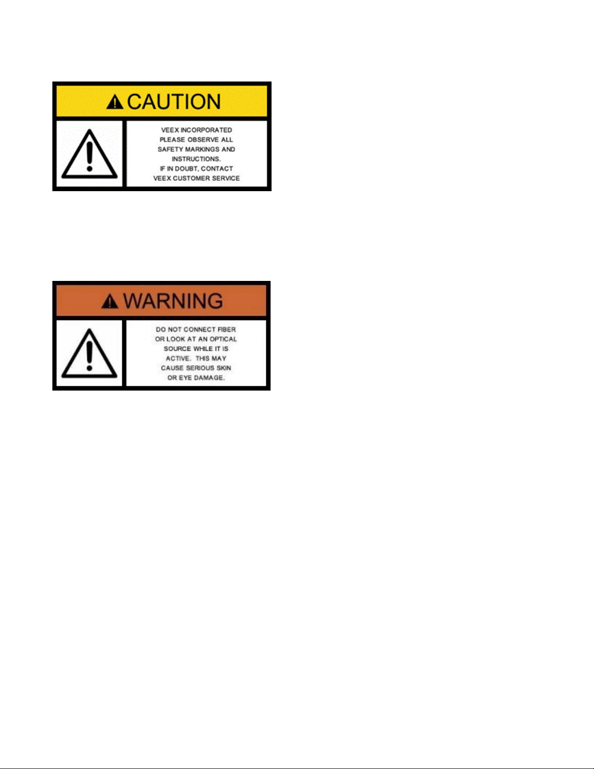
Optical Connectors
The test platform displays a laser warning icon when the laser source is active to alert the user
about a potentially dangerous situation. Make sure that optical sources are inactive before
connecting fiber to the test set to avoid skin or eye damage, or damage to the unit. It is
recommended to:
• Deactivate the laser before connecting or disconnecting optical cables or patchcords.
• Never look directly into an optical patchcord or an optical interface (e.g. CFP, CFP2, CFP4,
QSFP+, SFP+, SFP, OTDR, LS, VFL) while the laser is enabled. Even though optical
transceivers are typically fitted with Class 1 lasers, which are considered eye safe, optical
radiation for an extended period can cause irreparable damage to the eyes.
• Never use a fiber microscope to check the optical connectors when the laser source is
active.
Electrical Connectors
Telephone lines may carry dangerous voltages. Always connect the electrical test ports to
known test interfaces which carry low level signals.
FX8x Series User Manual Page 5 of 50

3.0 Introduction
The FX82/83/84/85/86/87 optical testers are a series of lightweight, handheld and rugged
devices with wide functionality. They are used for installing and maintaining point-to-point or
point-to-multipoint fiber networks.
The operator is assumed to have received basic training in fiber optics and related testing and
measurement practices.
For GPON measurements, please use the FX80 test unit (described in a separate
manual).
3.1 FX82/83/84/85/86/87 Features
Platform:
• High Contrast Monochrome LCD—visible outdoors and backlight for indoor or low light
conditions
• Handheld, lightweight rugged design
• Protective rubber boot with tilt bail stand
• Splash and dust resistant design
• Non-volatile storage for saved test results
• Up to 1920 single wavelength records
• Up to 960 tri-wavelength PON records
• Date/Time Stamp of test results
• Programmable thresholds with Pass/Fail
• USB (wired) or optional Bluetooth (wireless) interface for test result transfer
• Rechargeable Li-Polymer battery pack
• Micro-USB, 5 Volt DC charger
Software support:
• LTSync PC software for offloading test results and basic pdf/csv report generation
• Fiberizer Desktop Plus and Cloud versions for transfer of saved results from PC for
advanced post processing
• Fiberizer Mobile for USB tethering applications
FX8x Series User Manual Page 6 of 50

3.2 FX82/83/84/85/86/87 Test Functions
Optical Power Meter (OPM):
• Wavelength range 800 to 1650 nm
• Wide dynamic range InGaAs detector
• WaveID auto wavelength recognition (when paired with compatible VeEX OLS)
• Universal connector adapters
Optical Light Source (OLS):
• Dual, Tri and Quad wavelength options
• Single-mode: 1310, 1490, 1550, and 1625nm
• Quad CWDM per ITU-T G.694.2 grid
• Tunable DWDM per ITU-T G.694.1 grid
• Modes: CW or Modulated (270/330/1000/2000 Hz)
Visual Fault Locator (VFL):
• 650 nm laser with 1 mW output
• Universal 2.5 mm ferrule
Optical Talk Set (OTS):
• Full duplex, digital communication over single fiber under test
• 2.5 mm headset with volume control
FX8x Series User Manual Page 7 of 50
4.0 Overview
OPM
OLS
Uni-
OLTS
Bi-directional
CWDM OLS
DWDM TLS
SM/MM
SM
SM
SM
SM
SM
--
--
--
--
--
--
--
--
--
--
--
--
Up to 4 fixed
Up to 4 fixed
Up to 4 fixed
4 fixed λ per
C-ban
--
--
--
--
--
--
SM
--
--
--
--
-- --
--
--
--
--
--
--
Remote unit
--
--
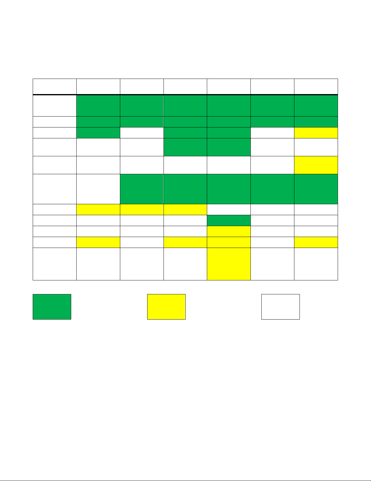
Table 1 FX8x Product Series
Model FX82 FX83 FX84 FX85 FX86 FX87
Main Test
Application
Fiber Type
OPM
OPM with
LS
OPM with
DWDM<
Light
Source
VFL
ORL
Talk Set
Bluetooth
VeriPHY
(not
currently
available)
directional
λ
λ
OLTS/ORL
λ
G.694.2
tunable in 50
GHz steps
per G.694.1
FX8x Series User Manual Page 8 of 50
Included
Optional
--
Not
supported
4.1 Hardware Control Elements
Colors, buttons, and screen fonts can insignificantly vary in different software
and hardware versions.
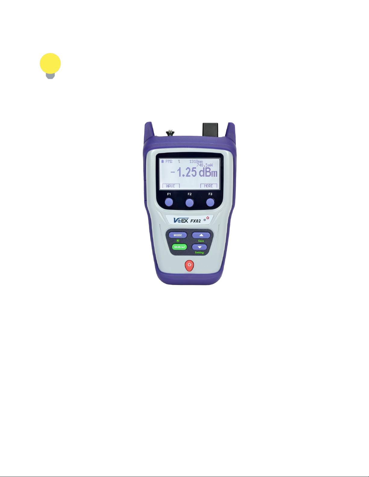
The FX8x series devices have the same front panel. The type and number of optical ports at
the top depends on the modifications and functions. The FX82 test unit is shown below.
FX82 front view
4.1.1 Optical ports
Optical ports (up to 4) are located at the top of the device.
4.1.2 Front buttons
|Power|: Turn device ON/OFF. Press and hold the button for 3 seconds. The display will
initially show the VeEX logo, current date and time, and current mode of operation.
|MODE|: Select the mode of operation, depending on the device.
|Shift/Enter|: Begin editing a parameter and confirm choice when setting up the device;
execute the selected action.
|Up|, |Down|: Change the selected parameter.
FX8x Series User Manual Page 9 of 50

4.1.3 Button combinations
|Shift/Enter|+|Up|: Save measurement results.
|Shift/Enter|+|Down|: Enter Instrument Settings mode.
|Shift/Enter|+|Mode|: Turn backlight ON/OFF.
|F1|, |F2|, |F3|: Context-defined, the function indicated at the screen bottom.
4.1.4 Service Ports
The micro-USB port located on the left side of the device is used for charging and
communication with a PC using the LTSync software.
The headphone jack (3.5 mm) located on the left side of the device is used for Talk Set
(optional for FX85 only).
FX8x Series User Manual Page 10 of 50
5.0 Getting Started
Before using the device for the first time, fully charge the battery and set the local date and
time.
5.1 Battery Charging
Every unit is equipped with a built-in, rechargeable Li-Polymer 3A, smart charge battery and it
is partially charged upon delivery. However, VeEX recommends charging the battery to full
capacity before using the test unit for the first time.
The device can be operated with the AC/ DC adaptor plugged in.
When the test unit is plugged into AC/DC power, the Plugged icon ( ) appears on the top left
corner of the display. When the device is operating on the internal battery, the Battery icon ( )
appears.
It is recommended to charge the battery at room temperature to preserve its life
and to obtain maximum charge.
To charge the test unit, connect the AC/DC adaptor supplied with the unit to the micro-USB
service port located on the left side of the device. The battery charging time depends on the
battery condition and ambient temperature. Use only the cables provided with the device to
charge the battery.
While the battery is charging, the LED indicator on the front panel will be orange. When the
battery is fully charged, the LED indicator will be green provided the test unit is powered ON.
The LED will turn off when the unit is powered OFF.
The Li-Polymer battery is designed for maximum safety. However, the battery
may explode, leak, or catch fire when:
• It is exposed to high temperatures or fire.
• It is opened or dismantled.
An auto-off feature, configured in the Settings mode, powers down the unit on selected time:
OFF, 15, 30, or 45 minutes.
5.1.1 Battery Replacement
Battery replacement in the field is not authorized or permitted. The unit must be returned to an
authorized VeEX service center or partner for repair.
FX8x Series User Manual Page 11 of 50
5.2 Setting Date and Time
Set the device date and time before attempting to save any measurement results:
To configure settings:
1. Power ON the device by pressing and holding the |Power| button for 3 seconds;
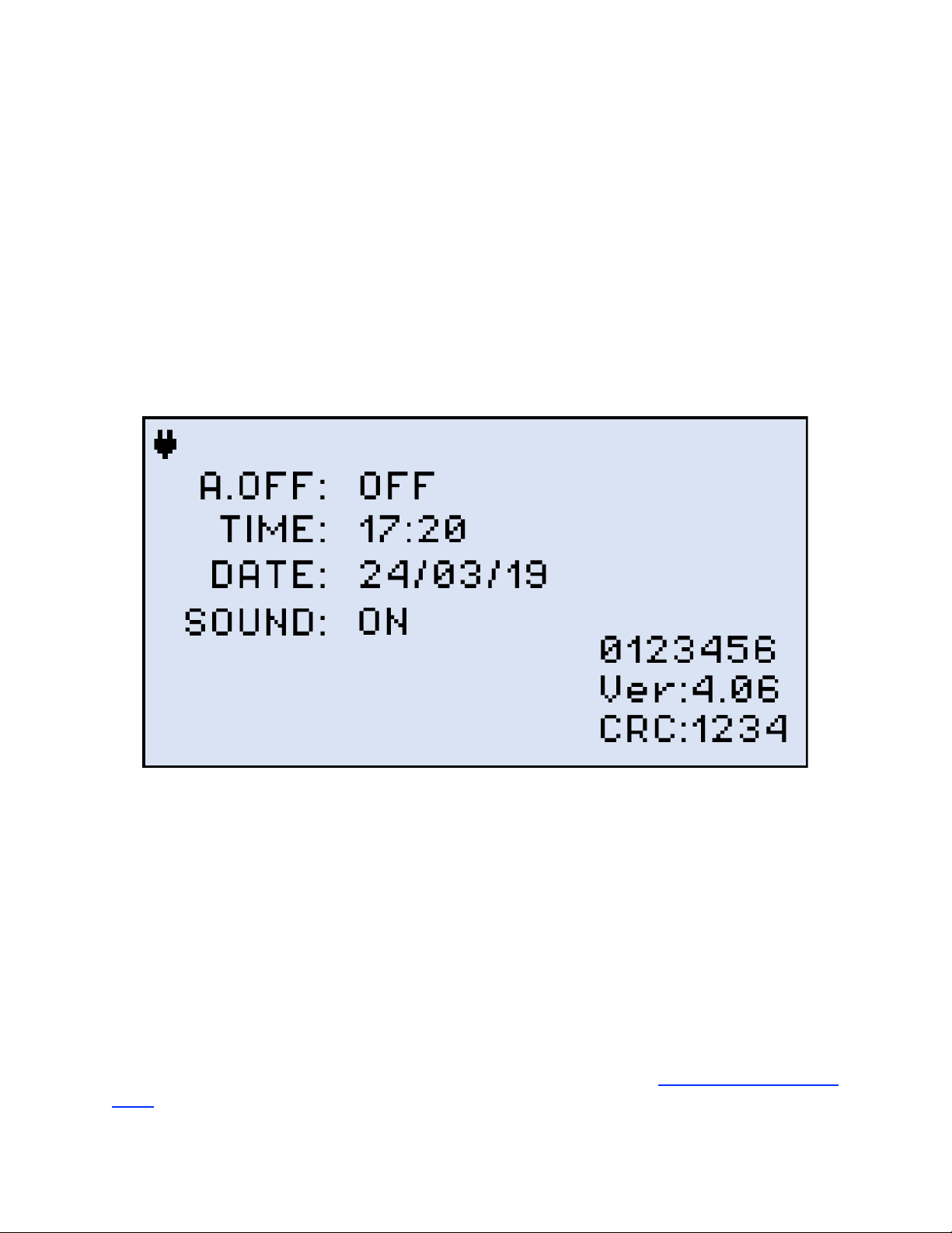
2. Press |Shift/Enter|+|Down| to enter the Settings mode. The following parameters can be set:
• Auto Shutdown mode
• Time
• Date
The test parameter currently selected and available to edit will flash.
Instrument Setting screen
3. Press |Up| and |Down| to select the parameter to edit.
4. Press |MODE| to select the field to edit, then change the value, if necessary, by pressing |Up| and
|Down|.
5. Press |Shift/Enter| to save the date and time settings.
5.3 Resetting the Device
To reset the device:
1. Disconnect external power supply from the device.
2. With the device OFF, press the red |Power| button and hold it for at least 20 seconds.
After the device reboots, set the date and time again (see Section 5.2. Setting Date and
Time).
FX8x Series User Manual Page 12 of 50

As a result of the reset, the threshold values and reference values will be lost.
These values must be reset. Also, ZERO level operation must be performed
again. For more information, see Sections 6.1. Setting ZERO Level and 6.2.1.
Setting Power Reference Level.
The reset DOES NOT erase any previously stored measurement data.
FX8x Series User Manual Page 13 of 50
6.0 Optical Power Measurement
This mode is available for FX82, FX84, FX85, and for FX87 as an option. The screenshots
shown below are from FX82. The other devices are equipped with a Light Source controlled by
the |F2| button which shows as LASER on their screens. The Broadband OPM is an InGaAs
detector with a wavelength range from 850 to 1650nm. The displayed power readings can be
absolute (dBm and watts) or relative (dB).
PM (PM1, PM2, PM3): use the OPM test mode to measure any incoming optical signal level
(CW, 270, 330, 1000, or 2000 Hz) between the wavelength range of 850-1650 nm. Select a
calibrated wavelength that matches the incoming source wavelength.
For best results, wait 15 minutes after the device is powered ON. This is
especially advisable in environments with extreme temperature changes.
6.1 Setting ZERO Level
The ZERO level MUST be set before first using the test unit for optical
power measurements. It is strongly advised to set the ZERO level BEFORE
every new batch of measurements and AFTER measurement conditions have
changed.
To set the ZERO level:
1. Press the |MODE| button until the PM1 or PM2 test mode appears at the upper left corner of the
display, then press |F3| (MORE). Make sure dust cap is closed.
PM Test Mode
FX8x Series User Manual Page 14 of 50
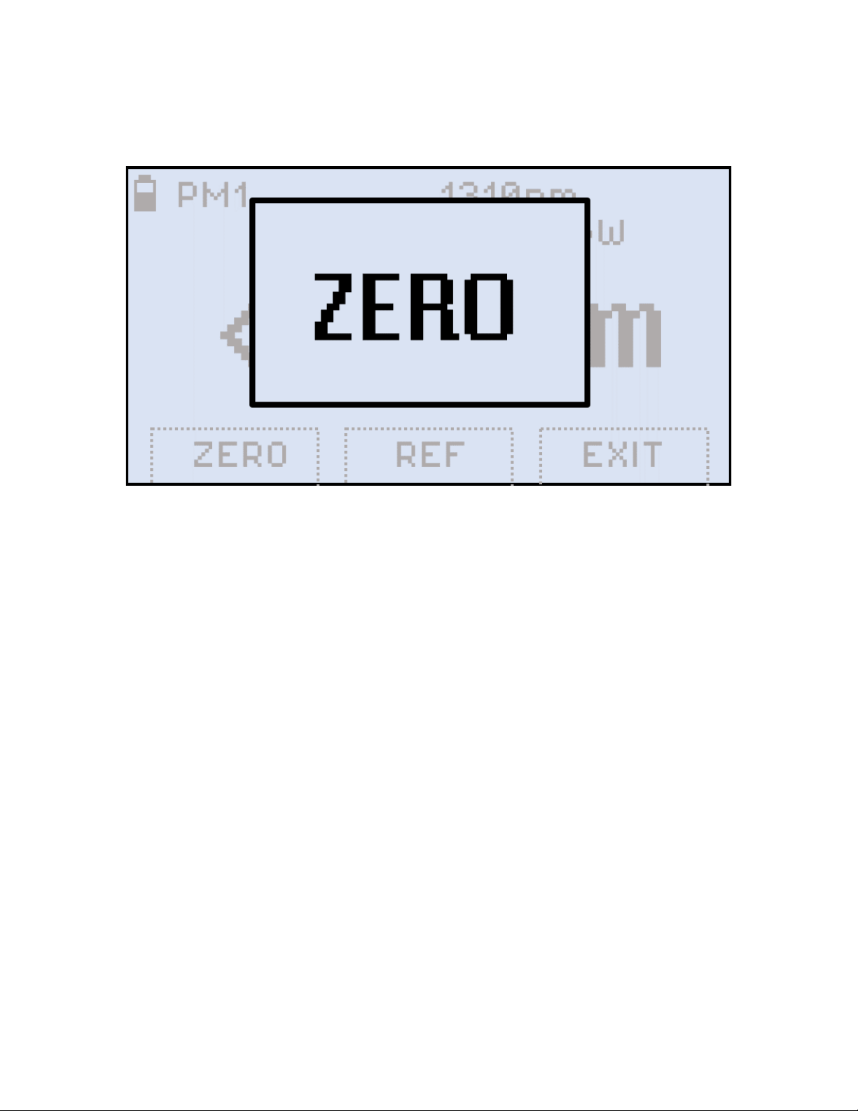
2. Press |F1| (ZERO). The ZERO notification shows briefly on the display.
Setting the ZERO level
The test unit is now ready for measurements.
6.2 OPM measurement
To measure the optical power in a fiber, insert the test fiber on the OPM test port and press
|MODE| until the PM1 or PM2 test mode appears at the upper left corner of the display.
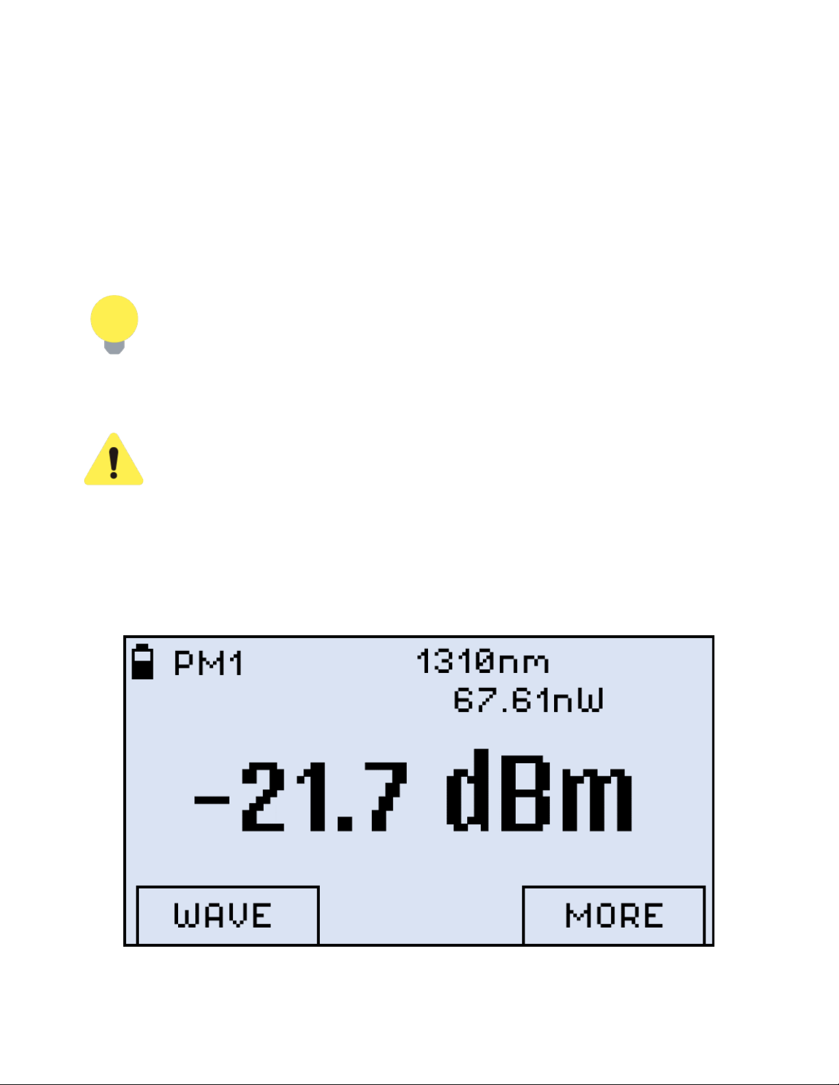
FX8x Series User Manual Page 15 of 50

Results of PM measurement
The fiber under test must have only one wavelength. If there are several
wavelengths, the measurement results will NOT be valid.
To change the wavelength, press the |F1| button (WAVE). The resulting calibrated wavelength
list is then shown below:
FX8x Series User Manual Page 16 of 50

Selecting a wavelength for PM measurement
Select a wavelength by pressing the |Up| and |Down| buttons, then press the |Shift/Enter|
button to confirm the choice. The new wavelength then appears in the top right corner of the
display. For the previous wavelength to remain effective, select a wavelength and then press
the |F1| (EXIT) button.
If the fiber under test carries a signal with WaveID details, select [ AUTO]. Then, the device
(FX82, FX84, or FX85) determines the wavelength automatically.
If the [ AUTO] option for a signal without WaveID or modulated is selected, the λ
value goes blank, and the measurement results are NOT valid.
6.2.1 Setting Power Reference Level
To measure the fiber under test span loss, first set a reference level for each test wavelength.
In the PM1/PM2 mode, press the |F3| button (MORE) and then press |F2| (REF).
FX8x Series User Manual Page 17 of 50

Selecting a reference option for PM measurement
• REF FIX command: sets the current power value as the reference level. Select REF FIX
with the cursor and press the |Shift/Enter| button. The value onscreen then changes
to -- -- dB. The current reference level value is shown on the second row to the right
(-6.86dBm in the example below).
Current power value set as the reference level
• REF MEM command: extracts the previous reference level.
FX8x Series User Manual Page 18 of 50

• REF OFF command: makes the previously stored reference level inactive, return to normal
absolute measurement.
• REF +/- command: finely adjusts the current reference level. Press the |Up| and |Down|
buttons to change the reference level by 0.01. To set the adjusted level as reference, press
|Shift/Enter|. To exit without setting, press |F3| (EXIT).
Broadband measurement taken against a reference level
FX8x Series User Manual Page 19 of 50

7.0 Optical Light Source
FX83 - 87 devices are equipped with Optical Light Source, so they can emit the calibrated
laser light into the fiber under test (FUT), to be received by a measuring device on the other
end. FX82 has no such functionality.
FX86 and FX87 employ CWDM and DWDM technologies respectively, and their Optical Light
Source menus are different (see Sections 7.1. Optical Light Source for FX86 and 7.2. Optical
Light Source for FX87 below).
To enter the Optical Light Source mode for FX83 – FX85:
1. Press the |MODE| button until the LS mode appears at the upper left corner of the
display, then press |F2| (LASER).
Optical Light Source mode
You can also enter the Optical Light Source mode from any PM mode:
FX8x Series User Manual Page 20 of 50

LASER button for Optical Light Source in PM mode
2. Press |F2| (LASER) button. The unit then shows the Optical Light Source menu:
Setting wavelength and mode for Optical Light Source
3. To select the necessary wavelength, press |Up| and |Down|.
4. To set the mode, press |F1| (MOD) repeatedly. You can choose from Continuous Wave
(CW), 270 Hz, 330 Hz, 1000 Hz, and 2000 Hz.
5. To confirm the settings, press |Shift/Enter|.
FX8x Series User Manual Page 21 of 50

7.1 Optical Light Source for FX86
FX86 employs Coarse Wavelength Division Multiplexing (CWDM) technology which is used for
measurements of CWDM optical element parameters.
To set and use the Optical Light Source for FX86:
1. Switch on FX86, the initial screen is shown. Note that the port frequencies are different,
and may need to be changed (see below):
Initial Settings screen for FX86 Optical Light Source (example)
2. Press |F1| (ALL ON) to switch on all the ports with the frequencies shown onscreen.
Press |F2| (ALL OFF) to switch all the ports off.
3. To set up a separate port, press |F3| (PORTS). The screen shown below appears:
FX8x Series User Manual Page 22 of 50

Ports Settings
4. Select the necessary port by pressing |Up| and |Down|.
5. To switch the selected port ON/OFF, press |Shift/Enter|.
6. To set up the selected port frequency, press |F1| (Freq). The screen shown below
appears:
Setting up a separate port
7. Select the necessary frequency by pressing |Up| and |Down|.
8. To turn on the WaveID function for the selected port, press |F2| (WID). Note that turning
on the WaveID function automatically selects the Continuous Wave frequency for this
port.
FX8x Series User Manual Page 23 of 50

9. To finalize the settings, press |F3| (EXIT).
Every port can have separate settings
Now the ports are emitting/not emitting laser light according to the settings.
FX8x Series User Manual Page 24 of 50

7.2 Optical Light Source for FX87
FX87 employs Dense Wavelength Division Multiplexing (DWDM) technology which permits
inserting up to 45 wavelengths into one fiber.
It is possible first set the Optical Light Source parameters and then connect the
fiber under test (FUT), or vice versa. The order does not matter.
The optical port used for the DWDM Light Source is always located on the left.
To set and use the Optical Light Source for FX87:
1. Switch on FX87, the initial screen is shown (see below):
DWDM Light Source mode
2. To turn the Laser on, press |F1| (LAS ON). The setting screen shown below appears:
FX8x Series User Manual Page 25 of 50

The setting screen for DWDM Light Source
The symbol in the top-right corner is flashing while the laser wavelength is being set.
3. To set the Channel, press |F2| (CHANNEL). Then select the Channel by pressing |Up|
and |Down|. To confirm the setting, press |Shift/Enter|.
Selecting wavelength for DWDM Light Source
4. To set the mode, press the |F3| button repeatedly. You can choose from Continuous
Wave (CW), 270 Hz, 330 Hz, 1000 Hz, and 2000 Hz, the selected value is shown
onscreen in the Laser field (see below):
FX8x Series User Manual Page 26 of 50

DWDM Light Source is set
FX8x Series User Manual Page 27 of 50

8.0 Visual Fault Locator (VFL)
The FX82, FX83, and FX84 can be equipped with a Visual Fault Locator (VFL).
To test a fiber line for continuity:
1. Connect the fiber to the VFL port.
2. Press the |MODE| button until get the VFL mode appears (see the Figure below).
Starting VFL mode
3. Press the |F1| (ON) button to begin the test.
FX8x Series User Manual Page 28 of 50

Starting VFL testing, continuous light
4. To modulate the light (1 or 2 Hz), press |F2| (1Hz) or |F3| (2Hz) respectively. The pressed button
then changes to CW, and you can press it to return to continuous light (see an example below).
VFL testing, modulated light
5. To switch from the VFL mode to another mode, press the |MODE| button.
FX8x Series User Manual Page 29 of 50

9.0 Optical Return Loss Measurement
One of the lasers generates an optical signal, which is inserted into the fiber under test (FUT)
via an optical splitter. The reflected signal from the FUT comes back to the optical port, and via
the optical splitter it is directed to the Optical Power Meter. The incoming signal level is
compared to the calibration values, and the Return Loss is shown onscreen.
To enter the Optical Return Loss mode, press |MODE| until ORL is indicated in the top left
corner:
ORL mode
9.1 Calibration before ORL measurement
Before ORL measurement, calibrate the test unit:
1. Press |F2| (LASER), to get the Laser submenu onscreen:
FX8x Series User Manual Page 30 of 50

ORL laser submenu
2. Select the necessary wavelength by pressing |Up| and |Down|. Confirm your selection
by pressing |Shift/Enter|. The screen like the one shown below appears:
ORL wavelength selected
Make sure the optical port is tightly capped during calibration.
3. Press |F1| (CALIBR). The CALIBRATION notification is then shown onscreen for
several seconds:
FX8x Series User Manual Page 31 of 50

ORL calibration in progress
4. Connect the reference cable to the ORL port. The reference cable is provided with the
device.
5. Press |F3| (REF_C), then set the -14.00 value by pressing |Up| and |Down|.
Setting ORL reference value
6. After setting the -14.00 value press |Shift/Enter|. The reference value is then saved to
the device memory.
7. Disconnect the reference cable and press |F1| (CALIBR) again. The CALIBRATION
notification is shown onscreen for several seconds again.
Now the device is ready for ORL measurement.
FX8x Series User Manual Page 32 of 50

9.2 Measuring ORL
To measure ORL:
1. While in the ORL mode, connect the fiber under test (FUT) to the optical port. The
measurement result is then shown onscreen (see an example below):
ORL measurement result
To save the current measurement result, press |Shift/Enter|+|Up|. The Saved notification
appears for several seconds, and the result is saved in the device memory.
Current ORL measurement result saved to device memory
FX8x Series User Manual Page 33 of 50

10.0 Talk Set
FX85 can be optionally equipped with a Talk Set, which allows technicians to exchange voice
information over the fiber under test (FUT). To use this functionality:
1. Press the |MODE| button until the VOICE mode appears at the upper left corner of the display:
Entering VOICE mode
2. To place a call, press |F1| (CALL):
Placing a call in VOICE mode
When the VOICE mode is on, measurements cannot be performed.
FX8x Series User Manual Page 34 of 50

The technician on the other end of the FUT must also have their unit in the
VOICE mode. Otherwise, the incoming call will not get through.
3. The technician on the other end of the FUT gets the Incoming Call notification on their unit:
Receiving a call in VOICE mode
To accept a call, the technician on the other end of the FUT must press |F2| (ANSWER):
4. To terminate the call, any of the technicians must press |F3| (CANCEL).
Button for terminating the call
FX8x Series User Manual Page 35 of 50

11.0 Viewing Measurement Results
To view measurement results, press the |MODE| button until the Read mode appears at the
upper left corner of the display and the results are shown:
Viewing Measurement Results (Read mode)
The FX82 can be optionally equipped with Bluetooth. If so, the Bluetooth sign
appears in the top right corner in the Read mode.
FX8x Series User Manual Page 36 of 50

11.1 Editing Notes to Measurement Results
By default, every measurement is appended with the ‘COMMENT###’ note, where ### is the
number incremented by “1” with every measurement. This is convenient when measuring
several fibers within one batch or one splitter.
The note can be edited as described below, then the updated text applies to the next
measurement.
1. Press |F3| (MORE), then press |F1| (NOTE). The screen shown below then appears.
Editing comments to future measurement results
2. Press |F1| (INDEX/COMMENT) until the cursor starts flashing in the INDEX field or in the
COMMENT field.
3. Then use the |Up| and |Down| buttons to position the cursor in the set of symbols. The active
symbol then gets flashing. Use the |Up| and |Down| buttons to select another symbol if necessary.
4. Press the |Shift/Enter| button to insert the selected symbol from the list at the end of the selected
field.
The comment can include up to 10 symbols (including 3 symbols of the Index).
5. To erase the last symbol of the top line, place the cursor after that symbol, then select the left arrow
in the set of symbols (
6. To save the note for the next measurement and exit the NOTE mode, press the |F3| (EXIT) button.
) and execute the command by pressing the |Shift/Enter| button.
FX8x Series User Manual Page 37 of 50

To save the current measurement results with the current note:
• Press the |Shift/Enter|+|Up| button combination (Save). The Saved notification is then
briefly shown onscreen, and current measurement results with the current note are saved
in the device memory.
Once the note is saved with measurement results, it cannot be edited.
FX8x Series User Manual Page 38 of 50

12.0 Downloading Measurement Results to PC
Test result are transferred from the FX82 device to a PC via the supplied micro USB cable. A
Bluetooth option for the FX82 can also be optionally ordered to be included for wireless
transfer.
To transfer test results and create a measurement report, first install the LTSync PC software.
12.1 Installing the USB Driver for wired transfer
For a PC to work with the FX82 device, install the USB driver:
1. Plug in the FX82 device to the PC via the supplied micro USB cable. Check the Windows Device
Manager to see the FX82 item in the Other devices list. The FX82 item is shown with the
exclamation mark sign meaning that the driver for the device is not installed.
2. Download the driver from the VeEX web site at www.veexinc.com.
3. Go to Windows Device Manager, right-click the FX82 item, and then click Update driver (see an
example below). The Browse my computer for driver software window appears.
Installing the driver for FX82
FX8x Series User Manual Page 39 of 50

4. Define the path to the previously saved downloaded driver and click [ Next]. The driver installation
starts. After the installation is complete, a window appears indicating the driver has been installed
successfully (see below). Press Close.
The driver for FX82 successfully installed
FX8x Series User Manual Page 40 of 50

12.2 Transferring Measurement Results Via Cable
To transfer measurement results to the PC:
1. Launch LTSync and connect the FX82 to the PC via the micro-USB cable provided. The FX-Series
devices window appears (example shown below), with the device and its serial number recognized
by the program.
FX82 is connected to PC in LTSync, its serial number is recognized by the program
2. To view the measurement results on the PC, click the [ Download] button . (example below).
The measurement results are presented in a table. Use the scroll bar to view all results.
FX8x Series User Manual Page 41 of 50

Measurement results table
12.3 Preparing Measurement Results for Report
Enter the pertinent information into the fields in the Attributes section (see example above).
Filter the results by test group and/or wavelength by selecting the results to work with in the
main viewing area.
To download results for a specific time period, select the Hardware tab, and then select the
[ Load results for period] checkbox. The Filter box appears (see below).
Filtering measurement results by time
To delete a row(s) of results, select the checkbox next to the row(s) and then click the [ Delete
row] button .
To move a row to another group, highlight the row by clicking it. The border around the row
turns orange. Drag-and-drop the row to another group. Alternatively, highlight the row, click the
[ Move row ] button , and then highlight the desired group. Only one row at a time can be
moved. Move a row to another group only if there is no measurement with that wavelength in
the group.
To save the measurement results to a PC, click the [ Save to PC] button .
FX8x Series User Manual Page 42 of 50

To erase all test results from the FX-8x memory, select the Hardware tab and click the [ Erase
all memory] button .
12.4 Transferring Measurement Results Via Bluetooth
To be able to wirelessly transfer measurement results to the PC, the FX82 must
have Bluetooth option.
To transfer results via Bluetooth:
1. Pair the devices with the standard Bluetooth pairing procedure. If paired, the FX82 should appear in
the Bluetooth & Other Devices list in the Windows X Device Manager. See the icon example
below, taken in Win10:
FX-82 listed as a mobile device in the Bluetooth & other devices list
Please note that in the list above every FX8x series device (FX80, FX82, FX84,
FX85, etc.) are shown as FX8x; however, their serial numbers are different.
2. Launch LTSync on the PC.
3. Power on the FX-82 and enter the [Read] mode. The Bluetooth sign appears at the top right corner
of the screen (see below).
FX8x Series User Manual Page 43 of 50

Read mode with Bluetooth
4. In LTSync, select the Hardware tab and click the Bluetooth button . The FX82 serial number
appears in the [Connected to PC] field. If there are several devices connected to the PC via
Bluetooth, select the desired device in the drop-down list. After the FX82 and PC are connected,
the Bluetooth sign inverts its colors (see below).
FX82 and PC connected, shows Bluetooth sign with inverted colors
5. To transfer measurement results from FX82 to your PC, click [ Download] in the Memory
section of LTSync.
The time it takes to transfer results is dependent on the amount of data. To prepare results
reports from the downloaded measurements, see Section 12.3 Preparing Measurement
Results for Report.
FX8x Series User Manual Page 44 of 50

13.0 Uploading Measurement Results to Fiberizer™ Cloud
To access a Fiberizer Cloud account within the LTSync program:
1. Select the Cloud storage tab, and then click the Sign in to Fiberizer Cloud button, and then enter
the correct credentials in the resulting form.
Signing in to Fiberizer Cloud
2. Enter the user credentials in the resulting form.
Fiberizer Cloud Login screen
To register for a Fiberizer Cloud account, on the Cloud Storage tab, click the Register in
Fiberizer Cloud button. Alternatively, click the Sign up link on the Login screen.
To upload measurement results:
1. On the Cloud Storage tab, select a project from the Fiberizer Cloud account (see below).
Selecting a Fiberizer Cloud account for upload
FX8x Series User Manual Page 45 of 50

2. In the Results tab, select the Use VeEX workspace checkbox. This ensures that the measurement
results are uploaded to a dedicated VeEX folder in the Fiberizer Cloud account. To upload results to
Fiberizer Cloud folder in the root directory, leave the Use VeEX workspace checkbox unselected.
Saving to Fiberizer Cloud
3. Click the [Upload to Fiberizer Cloud] button to upload the measurement. LTSync creates a
folder in the Fiberizer™ Cloud account named after the connected device (for example, FX82
7654321) to which it uploads the results. The results saved in the Fiberizer Cloud account will be
accessible to other compatible VeEX devices.
• The status bar at the bottom left shows the status of the current operation.
• The measurement results are saved as an .oxtls file.
To log out from Fiberizer Cloud, on the Cloud Storage tab, click the [ Log out from Fiberizer
Cloud] button .
For more information on using LTSync, see the LTSync User Manual at
www.veexinc.com.
FX8x Series User Manual Page 46 of 50

14.0 Warranty and Software
Warranty Period: The warranty period for hardware, software and firmware is one (1) year
from the date of shipment to the customer. The warranty period for battery pack, LCD, LCD
touch panel, LCD protective cover, and accessories (including, but not limited to patch cords,
AC adaptor, SFP, USB adaptors, carrying case, carrying pouch) is limited to one (1) year.
Hardware Coverage: VeEX Inc. warrants hardware products against defects in materials and
workmanship. During the warranty period, VeEX Inc. will, at its sole discretion, either
• Repair the products
• Replace hardware which prove to be defective
provided that the products that the customer elects to replace are returned to VeEX Inc. by the
customer, along with Proof of Purchase, within thirty (30) days of the request by the customer,
freight prepaid.
Software Coverage: VeEX Inc. warrants software and firmware materials against defects in
materials and workmanship. During the warranty period, VeEX Inc. will, at its sole discretion,
either
• Repair the products
• Replace software and/or firmware which prove to be defective
provided that the products that the customer elects to replace are returned to VeEX Inc. by the
customer, along with proof of purchase, within thirty (30) days of the request by the customer,
freight prepaid.
Additionally, during the warranty period, VeEX Inc. will provide, without charge to the
customer, all fixes, patches and enhancements to the purchased software, firmware and
software options. VeEX Inc. does not warrant that all software or firmware defects will be
corrected. New enhancements attached to a software option require the option to be
purchased (at the time of order or the time of upgrade) in order to benefit from such
enhancements.
Limitations: The warranty is only for the benefit of the customer and not for the benefit of any
subsequent purchaser or licensee of any merchandise (hardware, software, firmware and/or
accessories).
Revoking the warranty: VeEX Inc. does not guarantee or warrant that the operation of the
hardware, software or firmware will be uninterrupted or error-free. The warranty will not apply
in any of the following cases:
• Improper or inadequate maintenance by the customer
• Damage due to software installed by the customer on the unit without prior authorization
(written) from VeEX Inc.
• Unauthorized alteration or misuse
• Damage occurred from operating the unit outside of the environmental specifications for the
product
• Improper installation by the customer
FX8x Series User Manual Page 47 of 50

15.0 Product Specifications
The most recent product specifications can be found on the VeEX web site at
www.veexinc.com.
FX8x Series User Manual Page 48 of 50

16.0 Certifications and Declarations
What is CE?
The CE marking is a mandatory European marking for
certain product groups to indicate conformity with the
essential health and safety requirements set out in European
Directives. To permit the use of a CE mark on a product,
proof that the item meets the relevant requirements must be
documented.
Use of this logo implies that the unit conforms to
requirements of European Union and European Free Trade
Association (EFTA). EN61010-1
For a copy of the CE Declaration of Conformity relating to
VeEX products, please contact VeEX customer service.
What is RoHS?
RoHS is the acronym for Restriction of Hazardous
Substances. Also known as Directive 2002/95/EC, it
originated in the European Union and restricts the use of
specific hazardous materials found in electrical and electronic
products. All applicable products imported into the EU market
after July 1, 2006 must pass RoHS compliance.
Click here for more information about RoHS compliance as it
relates to VeEX products or go to www.veexinc.com.
FX8x Series User Manual Page 49 of 50

17.0 About VeEX
VeEX Inc., an innovative, customer-focused communications test and measurement company,
develops next-generation test and monitoring solutions for telecommunication networks and
services. With a blend of advanced technologies and vast technical expertise, VeEX has
developed products that diligently address all stages of network deployment, maintenance,
and field service turn-up and integrate service verification features across DSL, fiber optics,
CATV/DOCSIS, mobile backhaul and fronthaul (CPRI/OBSAI), next-generation transport
network, fiber channel, carrier and metro Ethernet technologies, WLAN, and synchronization.
Visit us online at www.veexinc.com for the latest updates and additional documentation.
VeEX Incorporated
2827 Lakeview Court
Fremont, CA 94538
USA
Phone: +1 510 651 0500
Fax: +1 510 651 0505
Customer Care
Phone: + 1 510 651 0505
Email: customercare@veexinc.com
FX8x Series User Manual Page 50 of 50
 Loading...