

VeEX FX8 Series, FX83, FX82, FX84 User Manual

Contents
1.0 About This User Manual ........................................................................................... 4
2.0 Safety Information ..................................................................................................... 5
3.0 Introduction ............................................................................................................... 6
3.1 FX82/83/84/85/86/87 Features .............................................................................................. 6
3.2 FX82/83/84/85/86/87 Test Functions .................................................................................... 7
4.0 Overview .................................................................................................................... 8
4.1 Hardware Control Elements ................................................................................................. 9
4.1.1 Optical ports ............................................................................................................................................9
4.1.2 Front buttons ...........................................................................................................................................9
4.1.3 Button combinations ........................................................................................................................... 10
4.1.4 Service Ports ........................................................................................................................................ 10
5.0 Getting Started ........................................................................................................ 11
5.1 Battery Charging ................................................................................................................ 11
5.1.1 Battery Replacement............................................................................................................................ 11
5.2 Setting Date and Time ........................................................................................................ 12
5.3 Resetting the Device .......................................................................................................... 12
6.0 Optical Power Measurement .................................................................................. 14
6.1 Setting ZERO Level ............................................................................................................ 14
6.2 OPM measurement ............................................................................................................. 15
6.2.1 Setting Power Reference Level ........................................................................................................... 17
7.0 Optical Light Source ............................................................................................... 20
7.1 Optical Light Source for FX86 ........................................................................................... 22
7.2 Optical Light Source for FX87 ........................................................................................... 25
8.0 Visual Fault Locator (VFL) ...................................................................................... 28
9.0 Optical Return Loss Measurement ........................................................................ 30
9.1 Calibration before ORL measurement .............................................................................. 30
9.2 Measuring ORL ................................................................................................................... 33
10.0 Talk Set .................................................................................................................... 34
11.0 Viewing Measurement Results ............................................................................... 36
11.1 Editing Notes to Measurement Results ............................................................................ 37
12.0 Downloading Measurement Results to PC............................................................ 39
12.1 Installing the USB Driver for wired transfer...................................................................... 39
12.2 Transferring Measurement Results Via Cable .................................................................. 41
12.3 Preparing Measurement Results for Report ..................................................................... 42
12.4 Transferring Measurement Results Via Bluetooth ........................................................... 43
13.0 Uploading Measurement Results to Fiberizer™ Cloud ........................................ 45
14.0 Warranty and Software ........................................................................................... 47
FX8x Series User Manual Page 2 of 50

15.0 Product Specifications ........................................................................................... 48
16.0 Certifications and Declarations .............................................................................. 49
17.0 About VeEX .............................................................................................................. 50
FX8x Series User Manual Page 3 of 50

1.0 About This User Manual
This manual is suitable for novice, intermediate, and experienced users and is intended to help
successfully use the features and capabilities of the FX82/83/84/85/86/87 family of optical
testers. It is assumed that the user has basic computer experience and skills, and is familiar
with optical fiber testing, telecommunication concepts, terminology, and safety.
Every effort was made to ensure that the information contained in this user manual is accurate.
Information is subject to change without notice and we accept no responsibility for any errors
or omissions. In case of discrepancy, the web version takes precedence over any printed
literature. The content in this manual may vary from the software version installed in the unit.
© Copyright 2006-2019 VeEX, Inc. All rights reserved.
VeEX, VePAL, Sunrise Telecom, Agizer, Optixsoft, Sunlite, Sunset, RXT, MTT, Fiberizer, FX,
TX and OPX, are trademarks of VeEX, Inc. and/or its affiliates in the USA and certain other
countries. All trademarks or registered trademarks are the property of their respective
companies. No part of this document may be reproduced or transmitted electronically or
otherwise without written permission from VeEX, Inc.
This device uses software either developed by VeEX, Inc. or licensed by VeEX, Inc. from third
parties. The software is confidential and proprietary of VeEX, Inc. The software is protected by
copyright and contains trade secrets of VeEX, Inc. or VeEX's licensors. The purchaser of this
device agrees that it has received a license solely to use the software as embedded in the
device, and the purchaser is prohibited from copying, reverse engineering, decompiling, or
disassembling the software.
For more technical resources, visit the VeEX, Inc. web site at www.veexinc.com.
If you need assistance or have questions related to the use of this product, call or e-mail our
customer care department for customer support. Before contacting our customer care
department, you must have your product serial number and software version ready. Please
provide this number when contacting VeEX customer service.
Customer Care:
Phone: + 1 510 651 0500
E-mail: customercare@veexinc.com
Website: www.veexinc.com
FX8x Series User Manual Page 4 of 50
2.0 Safety Information
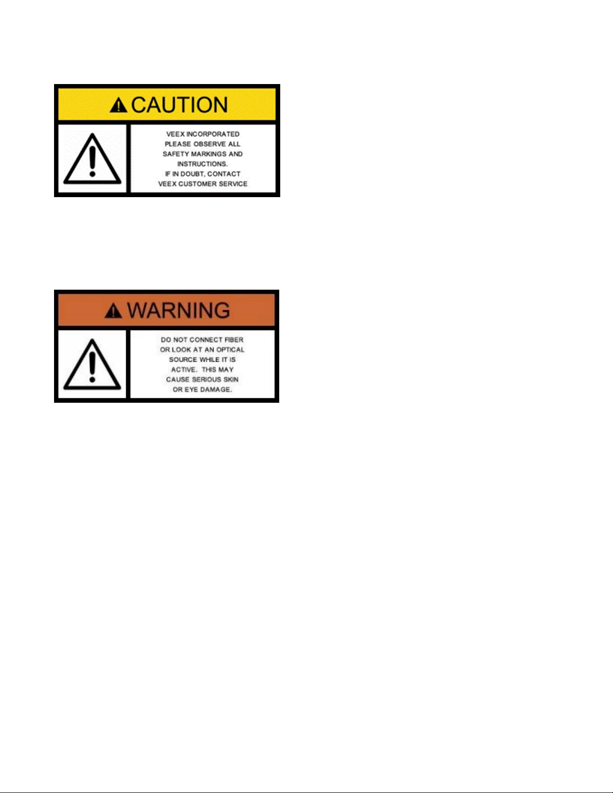
Safety precautions should be observed during all phases of operation of this instrument. The
instrument has been designed to ensure safe operation; however, please observe all safety
markings and instructions. Do not operate the instrument in the presence of flammable gases
or fumes or any other combustible environment. VeEX Inc. assumes no liability for the
customer's failure to comply with safety precautions and requirements.
Optical Connectors
The test platform displays a laser warning icon when the laser source is active to alert the user
about a potentially dangerous situation. Make sure that optical sources are inactive before
connecting fiber to the test set to avoid skin or eye damage, or damage to the unit. It is
recommended to:
• Deactivate the laser before connecting or disconnecting optical cables or patchcords.
• Never look directly into an optical patchcord or an optical interface (e.g. CFP, CFP2, CFP4,
QSFP+, SFP+, SFP, OTDR, LS, VFL) while the laser is enabled. Even though optical
transceivers are typically fitted with Class 1 lasers, which are considered eye safe, optical
radiation for an extended period can cause irreparable damage to the eyes.
• Never use a fiber microscope to check the optical connectors when the laser source is
active.
Electrical Connectors
Telephone lines may carry dangerous voltages. Always connect the electrical test ports to
known test interfaces which carry low level signals.
FX8x Series User Manual Page 5 of 50

3.0 Introduction
The FX82/83/84/85/86/87 optical testers are a series of lightweight, handheld and rugged
devices with wide functionality. They are used for installing and maintaining point-to-point or
point-to-multipoint fiber networks.
The operator is assumed to have received basic training in fiber optics and related testing and
measurement practices.
For GPON measurements, please use the FX80 test unit (described in a separate
manual).
3.1 FX82/83/84/85/86/87 Features
Platform:
• High Contrast Monochrome LCD—visible outdoors and backlight for indoor or low light
conditions
• Handheld, lightweight rugged design
• Protective rubber boot with tilt bail stand
• Splash and dust resistant design
• Non-volatile storage for saved test results
• Up to 1920 single wavelength records
• Up to 960 tri-wavelength PON records
• Date/Time Stamp of test results
• Programmable thresholds with Pass/Fail
• USB (wired) or optional Bluetooth (wireless) interface for test result transfer
• Rechargeable Li-Polymer battery pack
• Micro-USB, 5 Volt DC charger
Software support:
• LTSync PC software for offloading test results and basic pdf/csv report generation
• Fiberizer Desktop Plus and Cloud versions for transfer of saved results from PC for
advanced post processing
• Fiberizer Mobile for USB tethering applications
FX8x Series User Manual Page 6 of 50

3.2 FX82/83/84/85/86/87 Test Functions
Optical Power Meter (OPM):
• Wavelength range 800 to 1650 nm
• Wide dynamic range InGaAs detector
• WaveID auto wavelength recognition (when paired with compatible VeEX OLS)
• Universal connector adapters
Optical Light Source (OLS):
• Dual, Tri and Quad wavelength options
• Single-mode: 1310, 1490, 1550, and 1625nm
• Quad CWDM per ITU-T G.694.2 grid
• Tunable DWDM per ITU-T G.694.1 grid
• Modes: CW or Modulated (270/330/1000/2000 Hz)
Visual Fault Locator (VFL):
• 650 nm laser with 1 mW output
• Universal 2.5 mm ferrule
Optical Talk Set (OTS):
• Full duplex, digital communication over single fiber under test
• 2.5 mm headset with volume control
FX8x Series User Manual Page 7 of 50
4.0 Overview
OPM
OLS
Uni-
OLTS
Bi-directional
CWDM OLS
DWDM TLS
SM/MM
SM
SM
SM
SM
SM
--
--
--
--
--
--
--
--
--
--
--
--
Up to 4 fixed
Up to 4 fixed
Up to 4 fixed
4 fixed λ per
C-ban
--
--
--
--
--
--
SM
--
--
--
--
-- --
--
--
--
--
--
--
Remote unit
--
--
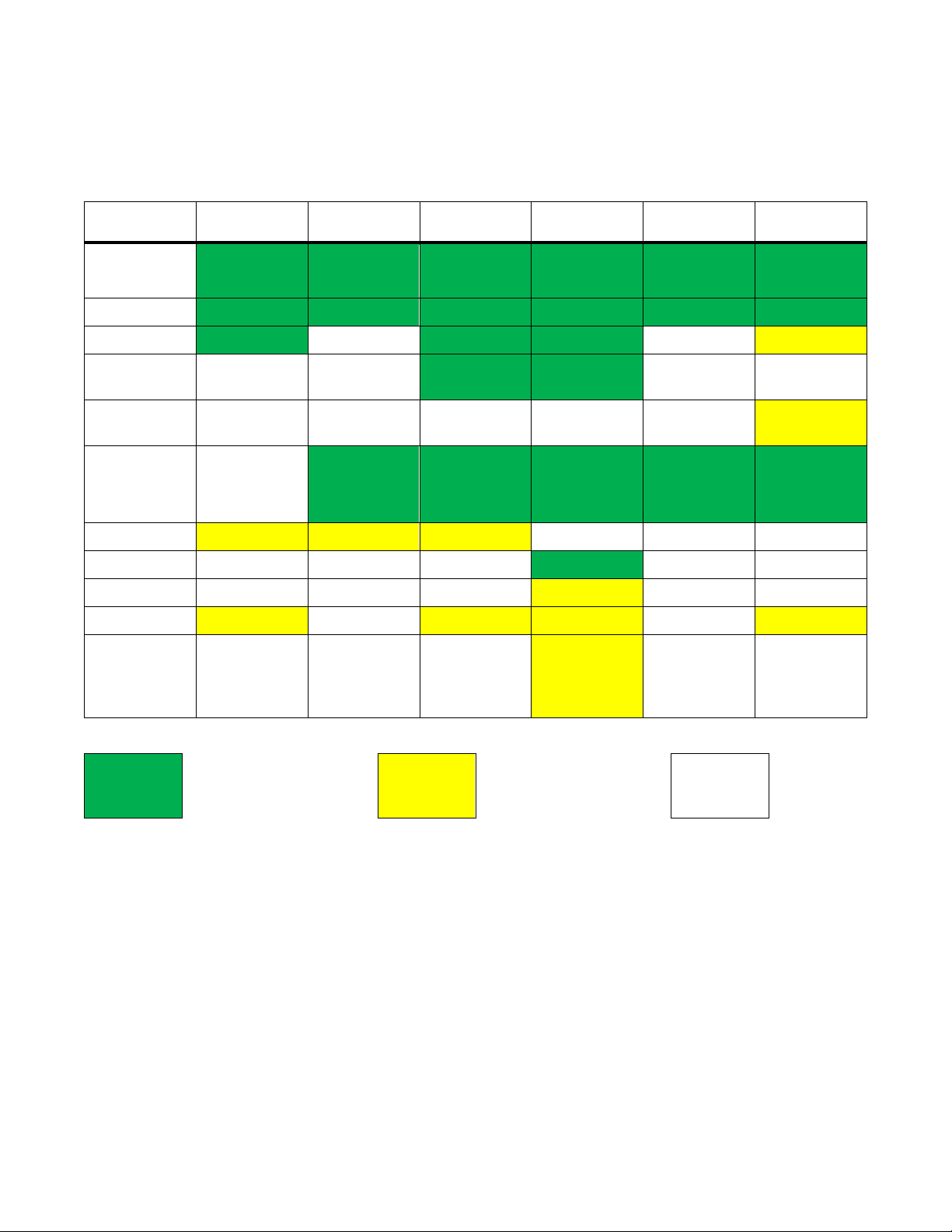
Table 1 FX8x Product Series
Model FX82 FX83 FX84 FX85 FX86 FX87
Main Test
Application
Fiber Type
OPM
OPM with
LS
OPM with
DWDM<
Light
Source
VFL
ORL
Talk Set
Bluetooth
VeriPHY
(not
currently
available)
directional
λ
λ
OLTS/ORL
λ
G.694.2
tunable in 50
GHz steps
per G.694.1
FX8x Series User Manual Page 8 of 50
Included
Optional
--
Not
supported
4.1 Hardware Control Elements
Colors, buttons, and screen fonts can insignificantly vary in different software
and hardware versions.
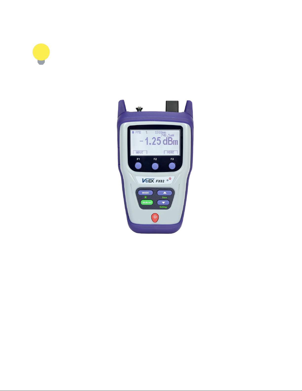
The FX8x series devices have the same front panel. The type and number of optical ports at
the top depends on the modifications and functions. The FX82 test unit is shown below.
FX82 front view
4.1.1 Optical ports
Optical ports (up to 4) are located at the top of the device.
4.1.2 Front buttons
|Power|: Turn device ON/OFF. Press and hold the button for 3 seconds. The display will
initially show the VeEX logo, current date and time, and current mode of operation.
|MODE|: Select the mode of operation, depending on the device.
|Shift/Enter|: Begin editing a parameter and confirm choice when setting up the device;
execute the selected action.
|Up|, |Down|: Change the selected parameter.
FX8x Series User Manual Page 9 of 50

4.1.3 Button combinations
|Shift/Enter|+|Up|: Save measurement results.
|Shift/Enter|+|Down|: Enter Instrument Settings mode.
|Shift/Enter|+|Mode|: Turn backlight ON/OFF.
|F1|, |F2|, |F3|: Context-defined, the function indicated at the screen bottom.
4.1.4 Service Ports
The micro-USB port located on the left side of the device is used for charging and
communication with a PC using the LTSync software.
The headphone jack (3.5 mm) located on the left side of the device is used for Talk Set
(optional for FX85 only).
FX8x Series User Manual Page 10 of 50
5.0 Getting Started
Before using the device for the first time, fully charge the battery and set the local date and
time.
5.1 Battery Charging
Every unit is equipped with a built-in, rechargeable Li-Polymer 3A, smart charge battery and it
is partially charged upon delivery. However, VeEX recommends charging the battery to full
capacity before using the test unit for the first time.
The device can be operated with the AC/ DC adaptor plugged in.
When the test unit is plugged into AC/DC power, the Plugged icon ( ) appears on the top left
corner of the display. When the device is operating on the internal battery, the Battery icon ( )
appears.
It is recommended to charge the battery at room temperature to preserve its life
and to obtain maximum charge.
To charge the test unit, connect the AC/DC adaptor supplied with the unit to the micro-USB
service port located on the left side of the device. The battery charging time depends on the
battery condition and ambient temperature. Use only the cables provided with the device to
charge the battery.
While the battery is charging, the LED indicator on the front panel will be orange. When the
battery is fully charged, the LED indicator will be green provided the test unit is powered ON.
The LED will turn off when the unit is powered OFF.
The Li-Polymer battery is designed for maximum safety. However, the battery
may explode, leak, or catch fire when:
• It is exposed to high temperatures or fire.
• It is opened or dismantled.
An auto-off feature, configured in the Settings mode, powers down the unit on selected time:
OFF, 15, 30, or 45 minutes.
5.1.1 Battery Replacement
Battery replacement in the field is not authorized or permitted. The unit must be returned to an
authorized VeEX service center or partner for repair.
FX8x Series User Manual Page 11 of 50
5.2 Setting Date and Time
Set the device date and time before attempting to save any measurement results:
To configure settings:
1. Power ON the device by pressing and holding the |Power| button for 3 seconds;
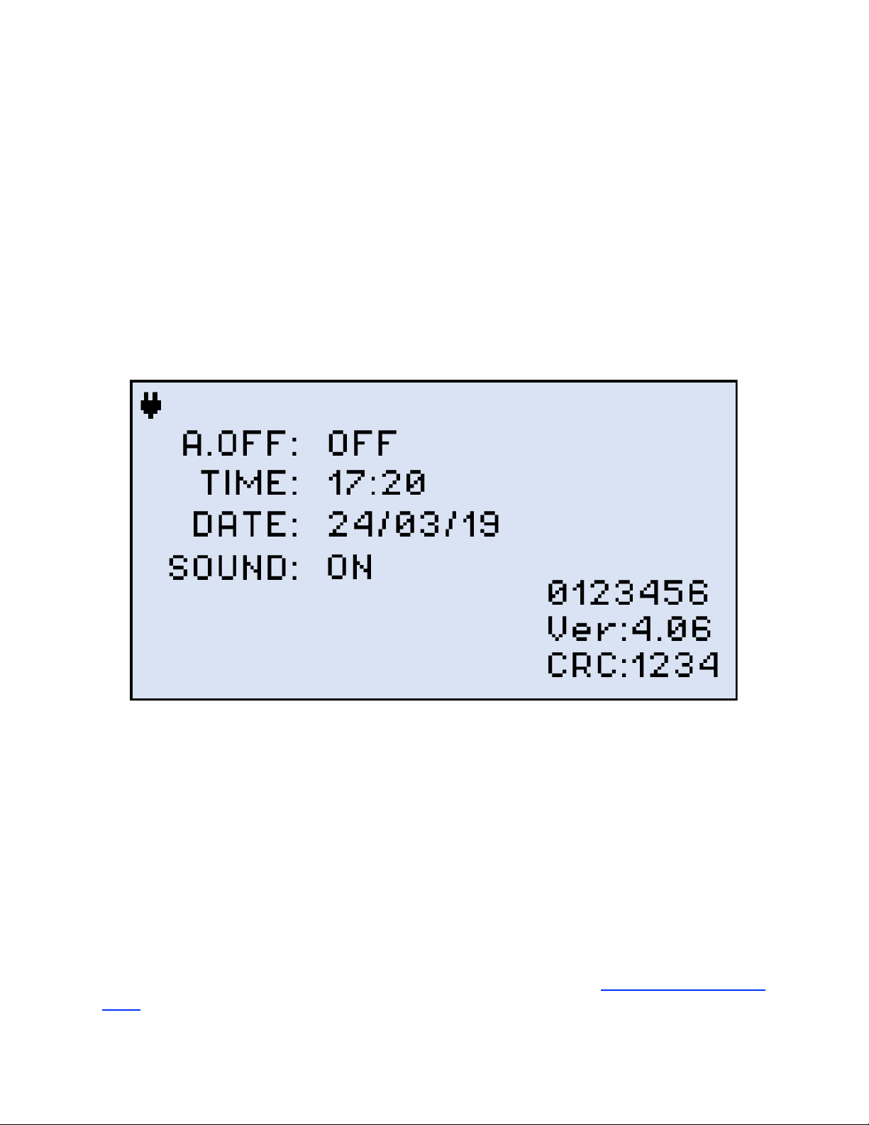
2. Press |Shift/Enter|+|Down| to enter the Settings mode. The following parameters can be set:
• Auto Shutdown mode
• Time
• Date
The test parameter currently selected and available to edit will flash.
Instrument Setting screen
3. Press |Up| and |Down| to select the parameter to edit.
4. Press |MODE| to select the field to edit, then change the value, if necessary, by pressing |Up| and
|Down|.
5. Press |Shift/Enter| to save the date and time settings.
5.3 Resetting the Device
To reset the device:
1. Disconnect external power supply from the device.
2. With the device OFF, press the red |Power| button and hold it for at least 20 seconds.
After the device reboots, set the date and time again (see Section 5.2. Setting Date and
Time).
FX8x Series User Manual Page 12 of 50

As a result of the reset, the threshold values and reference values will be lost.
These values must be reset. Also, ZERO level operation must be performed
again. For more information, see Sections 6.1. Setting ZERO Level and 6.2.1.
Setting Power Reference Level.
The reset DOES NOT erase any previously stored measurement data.
FX8x Series User Manual Page 13 of 50
6.0 Optical Power Measurement
This mode is available for FX82, FX84, FX85, and for FX87 as an option. The screenshots
shown below are from FX82. The other devices are equipped with a Light Source controlled by
the |F2| button which shows as LASER on their screens. The Broadband OPM is an InGaAs
detector with a wavelength range from 850 to 1650nm. The displayed power readings can be
absolute (dBm and watts) or relative (dB).
PM (PM1, PM2, PM3): use the OPM test mode to measure any incoming optical signal level
(CW, 270, 330, 1000, or 2000 Hz) between the wavelength range of 850-1650 nm. Select a
calibrated wavelength that matches the incoming source wavelength.
For best results, wait 15 minutes after the device is powered ON. This is
especially advisable in environments with extreme temperature changes.
6.1 Setting ZERO Level
The ZERO level MUST be set before first using the test unit for optical
power measurements. It is strongly advised to set the ZERO level BEFORE
every new batch of measurements and AFTER measurement conditions have
changed.
To set the ZERO level:
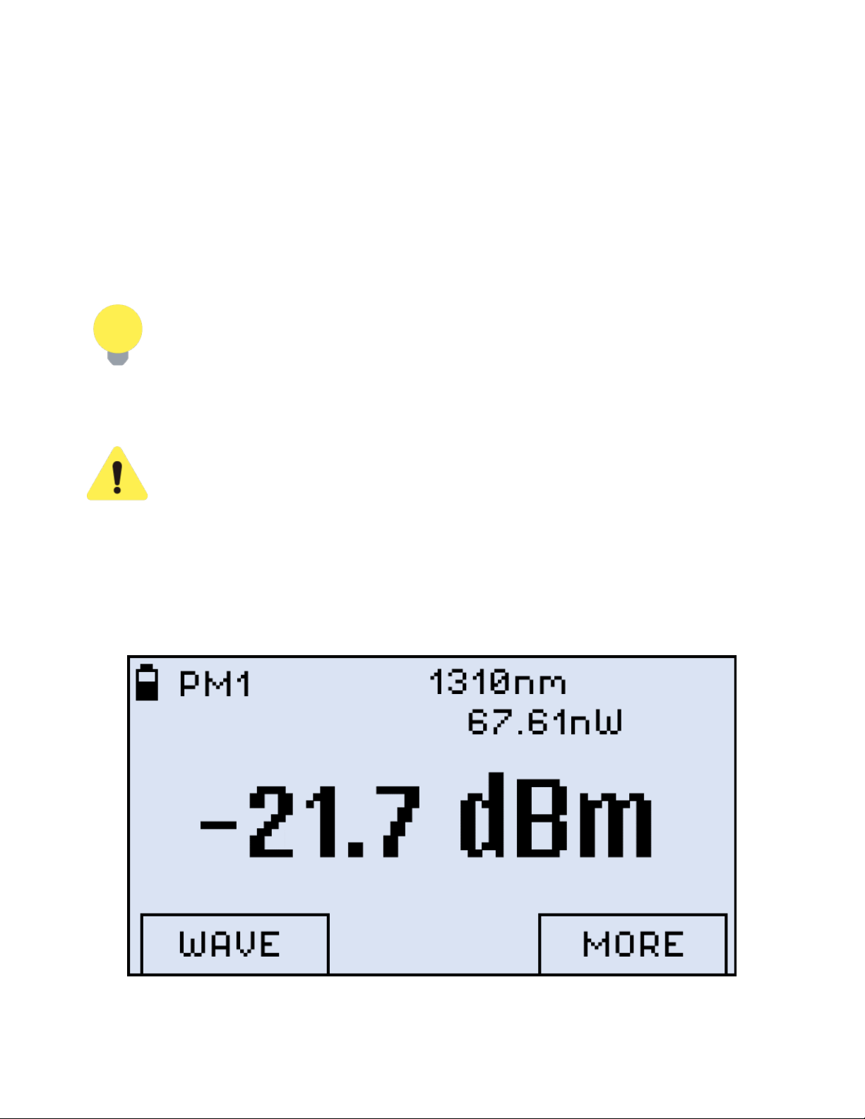
1. Press the |MODE| button until the PM1 or PM2 test mode appears at the upper left corner of the
display, then press |F3| (MORE). Make sure dust cap is closed.
PM Test Mode
FX8x Series User Manual Page 14 of 50
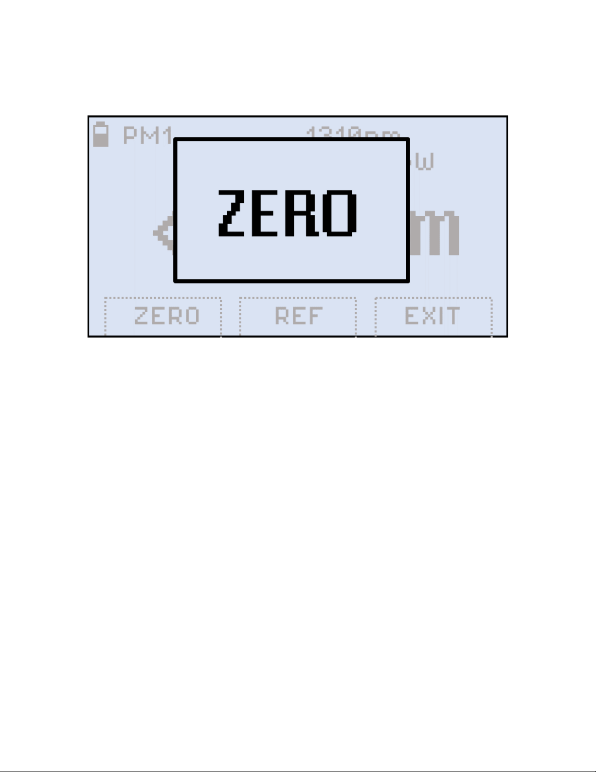
2. Press |F1| (ZERO). The ZERO notification shows briefly on the display.
Setting the ZERO level
The test unit is now ready for measurements.
6.2 OPM measurement
To measure the optical power in a fiber, insert the test fiber on the OPM test port and press
|MODE| until the PM1 or PM2 test mode appears at the upper left corner of the display.
FX8x Series User Manual Page 15 of 50
 Loading...