

Page 1
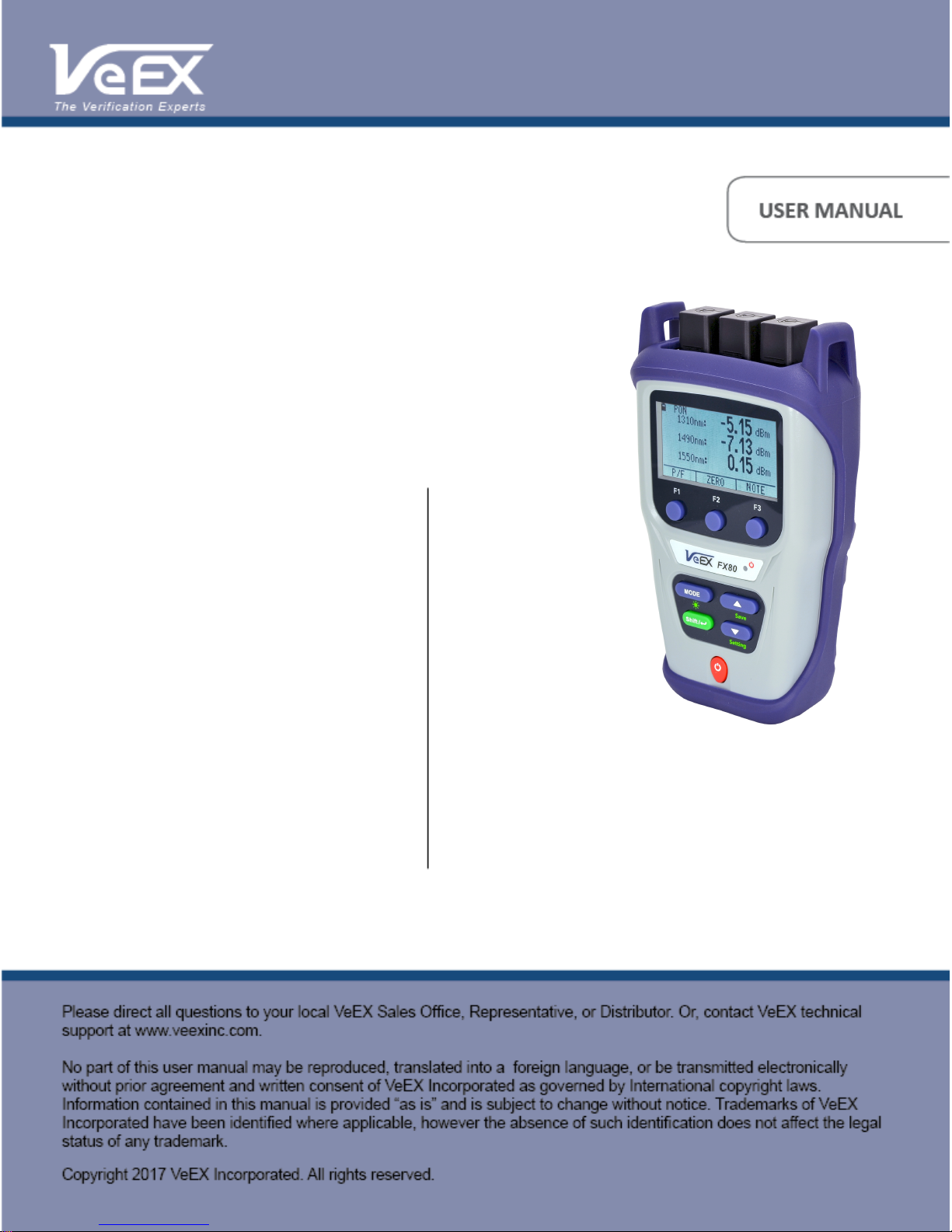
FX80 PON User Manual D07-00-115P RevA01
Page 1 of 36
FX80
PON Power Meter
Page 2

Table of Contents
FX80 PON User Manual D07-00-115P RevA01
Page 2 of 36
About This Manual . . . . . . . . . . . . . . . . . . . . . . . . . . . . . . . . . . . . . . . . . . . . . . . . . . . . . . . . . . Ê1
Disclaimer. . . . . . . . . . . . . . . . . . . . . . . . . . . . . . . . . . . . . . . . . . . . . . . . . . . . . . . . . . . . . . . . . Ê2
1. Introduction. . . . . . . . . . . . . . . . . . . . . . . . . . . . . . . . . . . . . . . . . . . . . . . . . . . . . . . . . . . . . . Ê3
1.1. FX80 Features . . . . . . . . . . . . . . . . . . . . . . . . . . . . . . . . . . . . . . . . . . . . . . . . . . . . . . . Ê3
2. Overview. . . . . . . . . . . . . . . . . . . . . . . . . . . . . . . . . . . . . . . . . . . . . . . . . . . . . . . . . . . . . . . . Ê5
2.1. Control Elements. . . . . . . . . . . . . . . . . . . . . . . . . . . . . . . . . . . . . . . . . . . . . . . . . . . . . . Ê5
2.2. FX80 Test Ports . . . . . . . . . . . . . . . . . . . . . . . . . . . . . . . . . . . . . . . . . . . . . . . . . . . . . . Ê6
2.2.1. Optical Ports . . . . . . . . . . . . . . . . . . . . . . . . . . . . . . . . . . . . . . . . . . . . . . . . . . . . . Ê6
2.2.2. Service Port . . . . . . . . . . . . . . . . . . . . . . . . . . . . . . . . . . . . . . . . . . . . . . . . . . . . . . Ê6
3. Getting Started . . . . . . . . . . . . . . . . . . . . . . . . . . . . . . . . . . . . . . . . . . . . . . . . . . . . . . . . . . . Ê7
3.1. Charging and Battery Care . . . . . . . . . . . . . . . . . . . . . . . . . . . . . . . . . . . . . . . . . . . . . . Ê7
3.2. Setting Date and Time . . . . . . . . . . . . . . . . . . . . . . . . . . . . . . . . . . . . . . . . . . . . . . . . . Ê7
3.3. Resetting your FX80 . . . . . . . . . . . . . . . . . . . . . . . . . . . . . . . . . . . . . . . . . . . . . . . . . . . Ê8
4. Optical Power Measurements . . . . . . . . . . . . . . . . . . . . . . . . . . . . . . . . . . . . . . . . . . . . . . . Ê9
4.1. Modes for Optical Power Measurements . . . . . . . . . . . . . . . . . . . . . . . . . . . . . . . . . . . Ê9
4.2. PON Power Measurements . . . . . . . . . . . . . . . . . . . . . . . . . . . . . . . . . . . . . . . . . . . . . Ê9
4.2.1. Setting ZERO Level. . . . . . . . . . . . . . . . . . . . . . . . . . . . . . . . . . . . . . . . . . . . . . . . Ê9
4.2.2. Pass/Fail Thresholds . . . . . . . . . . . . . . . . . . . . . . . . . . . . . . . . . . . . . . . . . . . . . . Ê10
4.2.2.1. Create User-Defined P/F Thresholds. . . . . . . . . . . . . . . . . . . . . . . . . . . . . . Ê10
4.2.2.2. Creating Threshold Profiles for Your Measurements . . . . . . . . . . . . . . . . . . Ê12
4.2.2.3. Loading the Saved Profile or the Default Profile . . . . . . . . . . . . . . . . . . . . . Ê14
4.2.3. Performing Optical Power Measurements in PON . . . . . . . . . . . . . . . . . . . . . . . Ê15
4.2.4. Adding Comments to Measurement Results. . . . . . . . . . . . . . . . . . . . . . . . . . . . Ê18
4.3. Broadband Power Measurements (Optional) . . . . . . . . . . . . . . . . . . . . . . . . . . . . . . . Ê19
4.3.1. Setting Power Reference Level. . . . . . . . . . . . . . . . . . . . . . . . . . . . . . . . . . . . . . Ê20
4.4. Visual Fault Locator (VFL) . . . . . . . . . . . . . . . . . . . . . . . . . . . . . . . . . . . . . . . . . . . . . Ê22
5. Downloading Measurement Results to PC. . . . . . . . . . . . . . . . . . . . . . . . . . . . . . . . . . . . . Ê25
5.1. Installing the FX40/45/80 USB driver . . . . . . . . . . . . . . . . . . . . . . . . . . . . . . . . . . . . . Ê25
5.2. Transferring measurement results to PC . . . . . . . . . . . . . . . . . . . . . . . . . . . . . . . . . . Ê27
6. Uploading Measurement Results to Fiberizer Cloud . . . . . . . . . . . . . . . . . . . . . . . . . . . . . Ê30
Warranty and Software. . . . . . . . . . . . . . . . . . . . . . . . . . . . . . . . . . . . . . . . . . . . . . . . . . . . . . Ê31
Appendix A: Optical Specifications. . . . . . . . . . . . . . . . . . . . . . . . . . . . . . . . . . . . . . . . . . . . . Ê33
Page 3

About This Manual
FX80 PON User Manual D07-00-115P RevA01
Page 3 of 36
Every effort was made to ensure that the information contained in this user manual is
accurate. Information is subject to change without notice and we accept no responsibility for
any errors or omissions. In case of discrepancy, the web version takes precedence over any
printed literature. The content in this manual may vary from the software version installed.
© Copyright 2017 VeEX, Inc. All rights reserved.
VeEX, VePAL, Sunrise Telecom, Agizer, Optixsoft, Sunlite, Sunset, RXT, MTT, OPX, and
Fiberizer are trademarks of VeEX, Inc. and/or its affiliates in the USA and certain other
countries. All trademarks or registered trademarks are the property of their respective
companies. No part of this document may be reproduced or transmitted electronically or
otherwise without written permission from VeEX, Inc.
The software and/or hardware described in this document are furnished under a license
agreement or nondisclosure agreement. The software is confidential and proprietary of VeEX,
Inc. The software is protected by copyright and contains trade secrets of VeEX, Inc. or
VeEX’s licensors. The software may be used or copied only in accordance with the terms of
the agreement. It is against the law to copy the software onto any medium except as
specifically allowed in the license or nondisclosure agreement. The purchaser may make one
copy of the software for backup purposes. The purchaser is prohibited from copying, reverse
engineering, decompiling, or disassembling the software.
This user manual is suitable for novice, intermediate, and experienced users and is intended
to help you successfully use the features and capabilities of the software. It is assumed that
the user has basic computer experience and skills, and is familiar with Optical Fiber,
telecommunication concepts, terminology, and safety. Please note that colors, buttons,
screen fonts and element positions in the screenshots and hardware pictures can
insignificantly vary in different software versions and device batches.
If you need assistance or have questions related to the use of this product, call or e-mail our
customer care department for customer support. Before contacting our customer care
department, you must have your product serial number and software version ready. Please
provide this number when contacting VeEX customer service. For more technical resources,
visit the VeEX, Inc. web site at www.veexinc.com.
Customer Care:
Phone: + 1 510 651 0500
E-mail: [email protected]
Website: www.veexinc.com
Page 4

Disclaimer
FX80 PON User Manual D07-00-115P RevA01
Page 4 of 36
Information in this document is subject to change without notice and does not represent a
commitment on the part of VeEX Inc. The software and/or hardware described in this
document are furnished under a license agreement or nondisclosure agreement. The
software may be used or copied only in accordance with the terms of the agreement. It is
against the law to copy the software on any medium except as specifically allowed in the
license or nondisclosure agreement. The purchaser may make one copy of the software for
backup purposes. No part of this manual and/or hardware and/or software may be
reproduced or transmitted in any form or by any means, electronic or mechanical, including
photocopying, recording, or information storage and retrieval system, for any purpose other
than the purchaser’s personal use, without the express written permission of VeEX Inc.
Throughout this book, trademarked names are used in an editorial manner only and to the
benefit of the trademark owner, with no intention of infringement of the trademark. Where
such designations appear in this book, they have been printed with initial capital letters.
VeEX and the VeEX logo are registered trademarks of VeEX INC.
© Copyright 2017 VeEX, Inc. All rights reserved.
Page 5

1. Introduction
FX80 PON User Manual D07-00-115P RevA01
Page 5 of 36
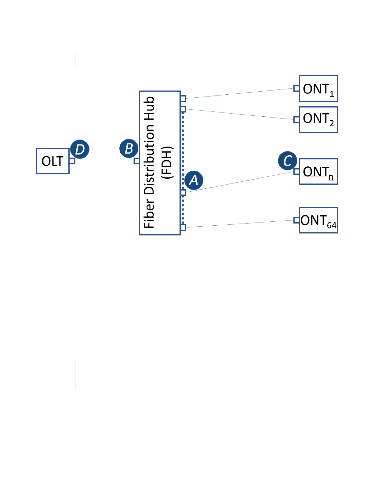
The FX80 power meter is designed to test passive optical networks (PON). It is used to
simultaneously measure all optical signal levels between the Optical Line Terminal (OLT) and
the Optical Network Unit/Terminal (ONU/ONT) on Gigabit B/E/GPON type networks. It can be
connected onto the PON network at any available access point along the Optical Distribution
Network (ODN). The access point can be at the OLT (central office - CO, head end or subheadend or remote hut), Fiber Distribution Point (FDP 1 or 2/splitter (if connectorized) or at
the ONU/ONT (customer premises - CP).ÊFigure A typical passive optical network (PON) with
possible points of measurement shows a typical passive optical network (PON) with the three
possible locations for measurement].
The unit passively monitors 1310, 1490 and the optional 1550 nm RF video downstream and
upstream PON optical power levels for compliance to standards. The measurement results
can be transfered to a PC or uploaded to the cloud using a Fiberizer Cloud account.
The operator is assumed to have received basic training in fiber optics and related testing
and measurement practices.
FX80 PON power meters are configured at the time of manufacture according to customer
requirements. A single device can be configured with optional VFL or BB-OPM.
1.1. FX80 Features
• Test B/E/GPON optical signal levels at OLT, FDP or ONT/ONU;
• Dual SC/APC Test Ports for Passive, Pass-Through Measurement of PON optical signal
levels;
• TFT LCD display with backlight;
• Measure the downstream 1490 nm and optional 1550 nm optical power transmitted from
the OLT to the ONU/ONT;
• Measure the upstream 1310 nm optical power (burst and CW mode) transmitted from
ONU/ONT to the OLT;
• Pass/Fail or numeric measurement results;
• Tone detection for fiber identification;
• Rechargeable Li-Poly battery or AC or USB powered operation
• Rugged compact design with protective rubber boot
• Optional Broadband InGaAs power meter (9 calibrated wavelengths: 850, 1300, 1310,
Page 6

1490, 1550, 1590, 1610, 1625, 1650 nm);
FX80 PON User Manual D07-00-115P RevA01
Page 6 of 36
• Visual Fault Locator (VFL) option;
• Client USB software (LTSync) for data transfer to PC or cloud for future analysis and
reporting.
Page 7
2. Overview
FX80 PON User Manual D07-00-115P RevA01
Page 7 of 36
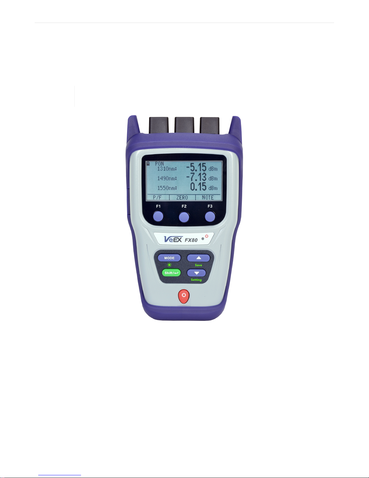
2.1. Control Elements
Colors, buttons, and screen fonts can slightly vary in different software and hardware
versions.
• |Power|: Turn device ON/OFF.Ê Press and hold the button for 3 sec.Ê The display will
initially show the VeEX logo, current date and time, and current mode of operation.
• |MODE|: Select the mode of operation: PON Burst, PON CW, Read, optional PM1,
optional VFL (default is PON Burst). For more information about FX80 modes, see
Section Modes for Optical Power Measurements.
• |Shift/Enter|: Start editing a parameter and confirm your choice when setting up the
device; execute the selected action.
• |Up|, |Down|: Change the selected parameter.
Figure 1. FX80 front view
Page 8
Button combinations:
FX80 PON User Manual D07-00-115P RevA01
Page 8 of 36
• |Shift/Enter|+|Up|: Save measurement results;
• |Shift/Enter|+|Down|: Enter Instrument Settings mode;
• |Shift/Enter|+|Mode|: Turn backlight ON/OFF.
|F1|, |F2|, |F3|: Context-defined, the function indicated at the screen bottom.
2.2. FX80 Test Ports
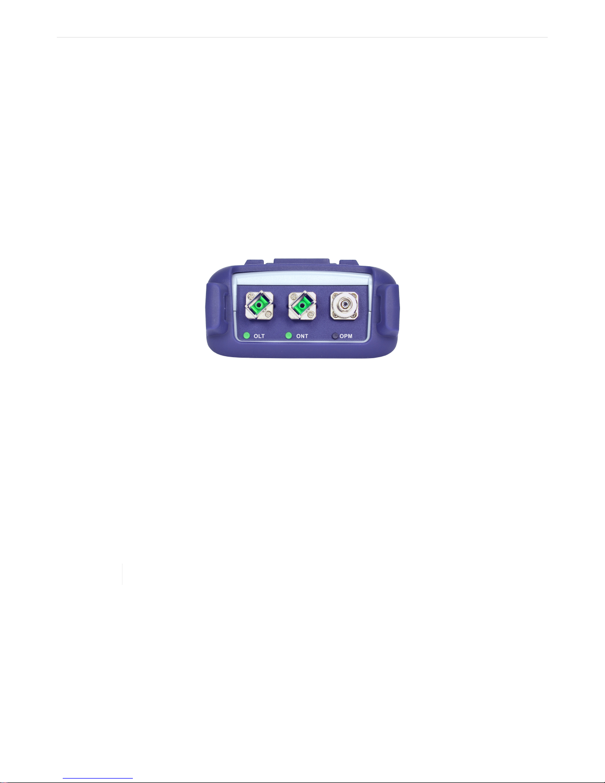
2.2.1. Optical Ports
Figure 2. FX80 optical ports
• OLT: Connect the FX80 to the fiber coming from the OLT to measure the downstream
optical power levels in the PON network for 1490 nm (always present on active network)
and 1550 nm (optional);
• ONT: Connect the FX80 to the fiber coming from the ONU/ONT to measure the upstream
optical power level in the PON network for 1310 nm transmission;
• OPM: Use for measuring optical power level with the help of the optional broadband
optical power meter;
• VFL: Use for 650 nm visual fault locator to visually locate breaks or excessive bends in
fibers which increase insertion loss.
The FX80 can be configured with either optional OPM or VFL, not both.
2.2.2. Service Port
The service port (micro-USB) located on the left side of the device is used for charging and
communication with a PC using LTSync software.
Page 9

3. Getting Started
FX80 PON User Manual D07-00-115P RevA01
Page 9 of 36
3.1. Charging and Battery Care
Before using the FX80 PON power meter, make sure the battery is charged. If the charge is
low, connect your FX80 service port to the charging unit provided with the device. While FX80
battery is charging, the LED indicator on the front panel will be orange. When the battery is
fully charged, the LED indicator will be green provided the FX80 is powered ON. The LED will
turn off when the unit is turned OFF.
When the FX80 is connected to AC power or an external power supply, the Plug icon ( ) will
appear in the top left corner of the screen. If the device operates with the internal battery, the
icon changes to Battery ( ).
3.2. Setting Date and Time
Set the device date and time before attempting to save any measurement results:
1. Turn ON the FX80 by pressing and holding the |Power| button for 3 seconds;
2. Press |Shift/Enter|+|Down| to enter the Settings mode. The following parameters can
be set:
◦ Auto Shutdown mode;
◦ Time;
◦ Date.
The current selected test parameter available to edit will be flashing.
Page 10
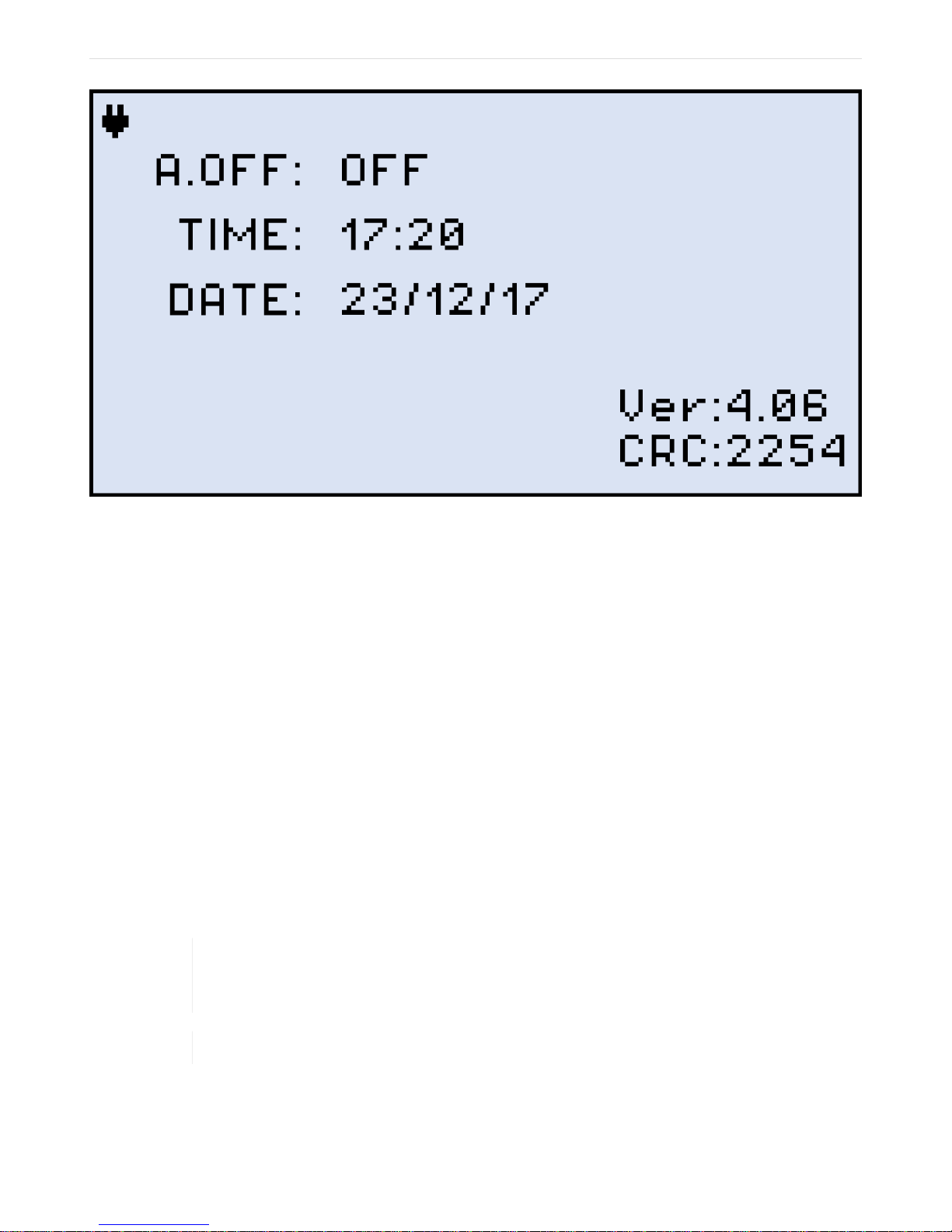
Figure 3. FX80 Instrument Setting screen
FX80 PON User Manual D07-00-115P RevA01
Page 10 of 36
3. Press |Up| and |Down| to select the parameter to edit.
4. Press
|Up| and |Down|.
5. Press |Shift/Enter| to save the date and time settings.
|MODE| to select the field to edit, then change the value if necessary by pressing
3.3. Resetting your FX80
On rare occassions, you may need to reset your FX80. To do this:
1. Disconnect external power supply from the device;
2. With device OFF, press the red |Power| button and hold it for at least 15 seconds.
The FX80 will reboot but you will need to reset the date and time (see Setting Date and
Time).
As a result of the reset, the threshold values and reference values will be lost. You need
to reset these values. You must also perform
ZERO Level).
ZERO level operation (see Setting
The reset DOES NOT erase any previously stored measurement data.
Page 11

4. Optical Power Measurements
FX80 PON User Manual D07-00-115P RevA01
Page 11 of 36
4.1. Modes for Optical Power Measurements
• PON Burst: use this OLT to ONT pass-through test mode to measures PON optical
levels on active, in-service PON networks.
• PON CW: use this OLT to ONT pass-through test mode to measures PON optical levels
on out-of-service PON networks that have ONU/ONT devices that can be set to
maintenance CW test mode.
• PM (PM1 or PM2): use the OPM test mode to measure any incoming optical signal level
(CW, 270, 1000, or 2000 Hz) between the wavelength range of 800-1700 nm. The user
must select a calibrated wavelength that matches the incoming source wavelength.
4.2. PON Power Measurements
For best results, we recommend you to wait for about 15 minutes after your FX80 is
powered ON. This is especially advisable in environments with extreme temperature
changes.
4.2.1. Setting ZERO Level
You MUST set the ZERO level before you first use your FX80 for PON power
To set the ZERO level:
1. Press the |MODE| button to enter the necessary PON measurement mode (PON Burst
or PON CW);
2. Press |F2| (ZERO). The ZERO notification will show briefly on the display.
measurements. We also strongly advise to set the ZERO level before every new batch of
measurements, and after your measurement conditions have changed.
Page 12
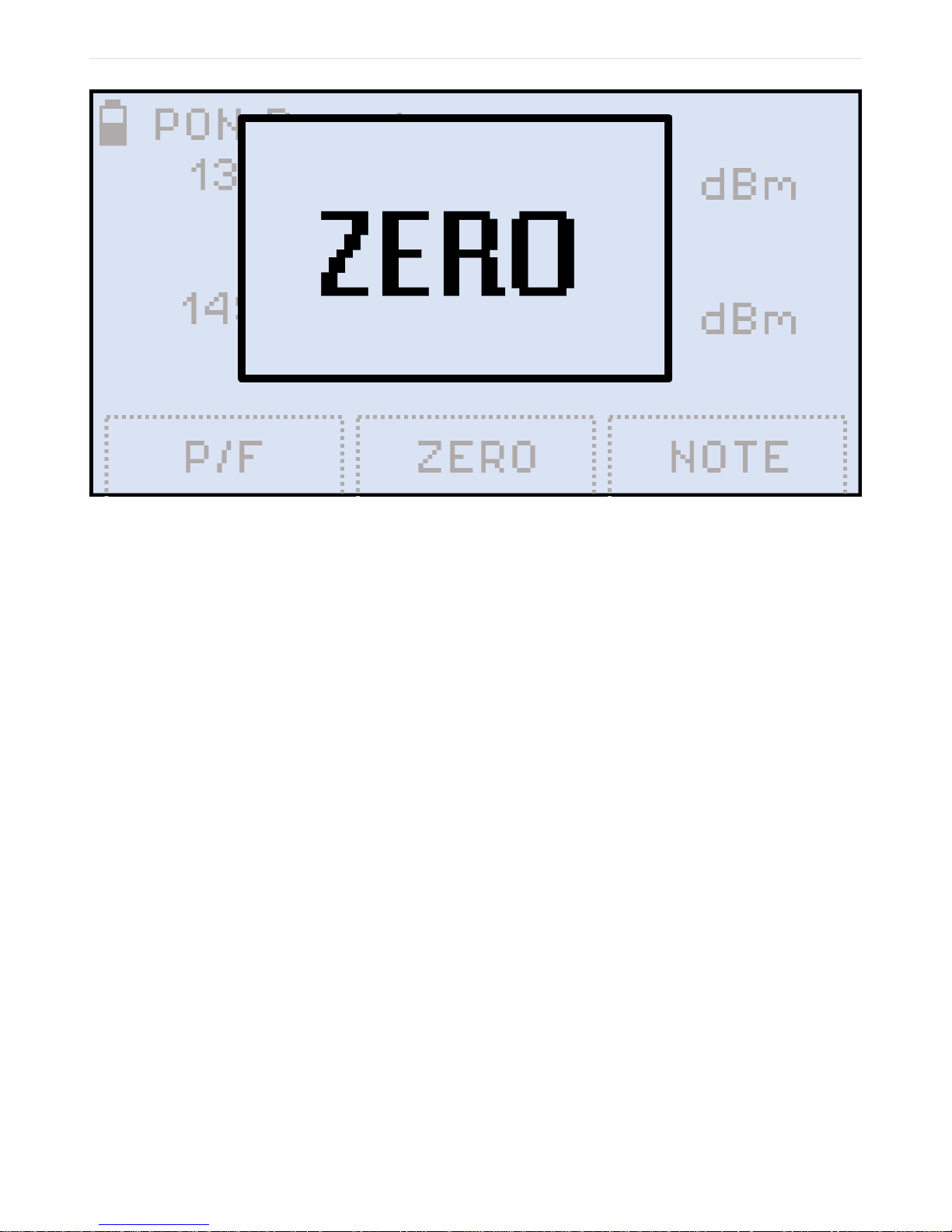
Figure 4. Setting the ZERO level
FX80 PON User Manual D07-00-115P RevA01
Page 12 of 36
The FX80 is now ready for measurements.
4.2.2. Pass/Fail Thresholds
In addition to measuring the downstream and upstream signal levels, the FX80 PON can also
be configured to provide the user with Pass/Fail (P/F) notification for each wavelength.
4.2.2.1. Create User-Defined P/F Thresholds
1. Press the |MODE| button to enter the necessary PON measurement mode (PON Burst
or PON CW) to set the thresholds. The result is shown below:
Page 13
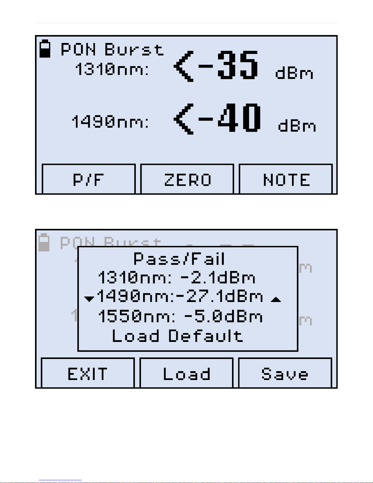
Figure 5. PON Burst mode
FX80 PON User Manual D07-00-115P RevA01
Page 13 of 36
2. Press F1 (P/F). The result is shown below:
3. Select the necessary wavelength Press the |Up| and |Down| arrow button to to select the
desired wavelength;
4. Press |Shift/Enter| to start setting the threshold. The corresponding value then starts
Figure 6. Setting Pass/Fail thresholds
Page 14

flashing.
FX80 PON User Manual D07-00-115P RevA01
Page 14 of 36
5. Set the necessary value pressing |Up| and |Down|;
6. Confirm your value by pressing |Shift/Enter|;
7. Press |F1| (EXIT) to exit the Setting Pass/Fail thresholds mode.
Your FX80 is now ready to start testing PON levels and compare PON optical power against
the P/F thresholds settings. The P/F thresholds settings will remain active until it is changed.
If the FX80 battery is allowed to get fully discharged, all settings such as Pass/Fail and
Date/Time settings will return to original factory defaults. If you wish to retain Pass/Fail
settings for future use, save it as a profile.
4.2.2.2. Creating Threshold Profiles for Your Measurements
One P/F profile with threshold values can be created and saved in memory for future recall.
To save the current set of thresholds as a profile:
1. In the P/F mode, enter the desired P/F values as described above, but do NOT exit the
Setting Pass/Fail thresholds mode;
2. To save the values just entered as the profile, press |F3| (Save);
3. To load the previously saved profile, press |F2| (Load). The values from your custom
profile will immediately appear on the screen;
4. To load the default threshold profile, press |Down| until Load Default is selected, then
press |Shift/Enter|. The values from the default profile immediately appear on the
screen.
Page 15
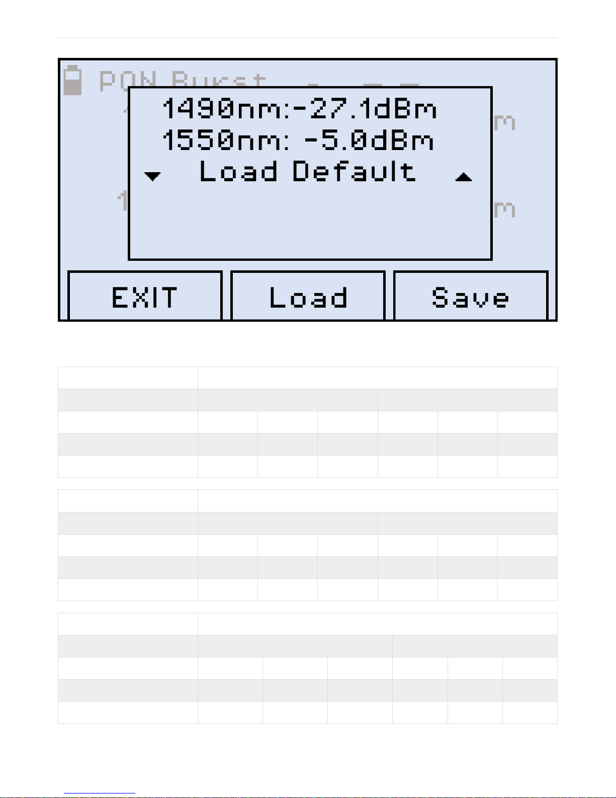
Figure 7. Selecting the Default profile
FX80 PON User Manual D07-00-115P RevA01
Page 15 of 36
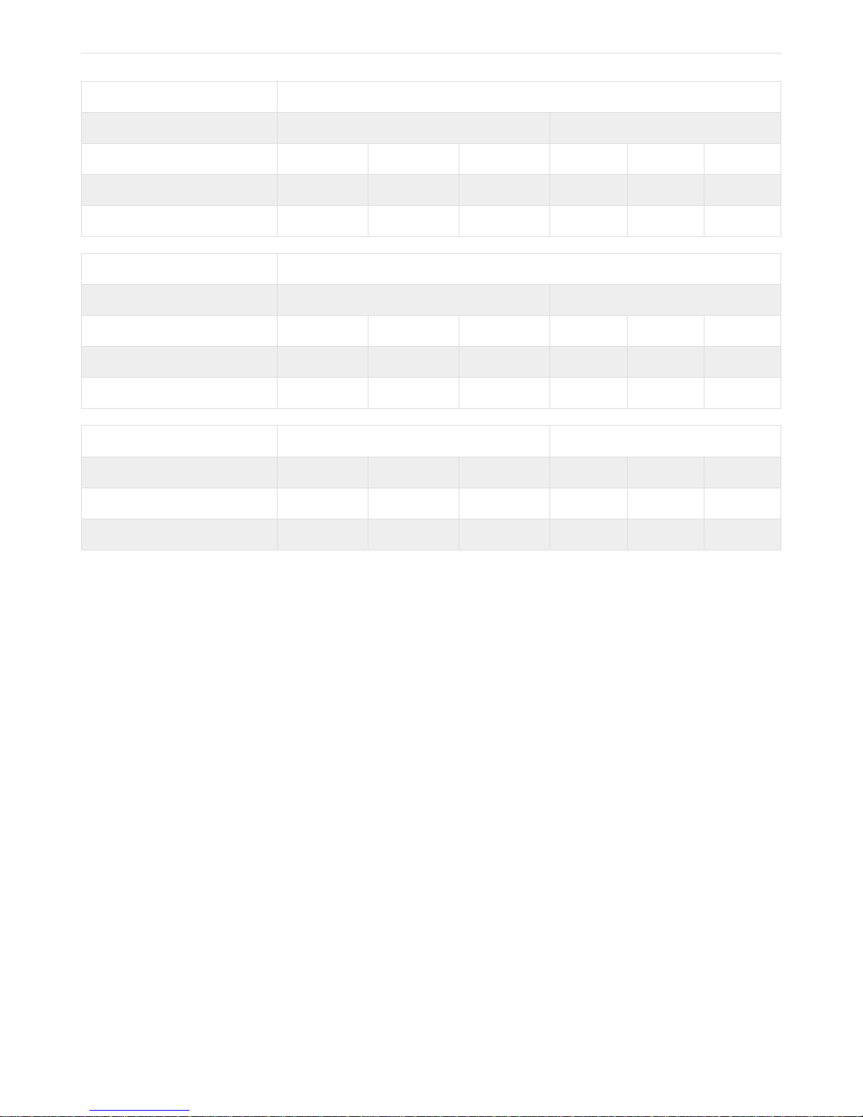
Table 1. ITU-T G.984-2 Standard Pass/Fail Thresholds
1.244 Gbs DS direction
1490nm OLT Launch Power 1490 ONT/ONU Receive Power
Class A Class B Class C Class A Class B Class C
Min Avg Power (dBm)
Max Avg Power
Min Avg Power (dBm)
Max Avg Power
Min Avg Power (dBm)
Max Avg Power
-4 1 5 -25 -25 -26
1 1 9 -4 -4 -4
2.48 Gbs DS direction
1490nm OLT Launch Power 1490 ONT/ONU Receive Power
Class A Class B Class C Class A Class B Class C
0 5 3 -21 -21 -28
4 9 7 -3 -7 -8
1.244 Gbs US direction
1310nm ONT/ONU Launch Power 1310 OLT Receive Power
Class A Class B Class C Class A Class B Class C
-3 -2 2 -24 -28 -29
2 3 7 -3 -7 -8
Page 16
622 Mbs DS direction
FX80 PON User Manual D07-00-115P RevA01
Page 16 of 36
1310nm ONT/ONU Launch Power 1310 ONU Receive Power
Class A Class B Class C Class A Class B Class C
Min Avg Power (dBm)
Max Avg Power
-6 -1 -1 -27 -27 -32
-1 4 4 -6 -6 -11
155 Mbs DS direction
1310nm ONT/ONU Launch Power 1310 ONU Receive Power
Class A Class B Class C Class A Class B Class C
Min Avg Power (dBm)
Max Avg Power
-6 -4 -2 -27 -30 -33
0 2 4 -5 -8 -11
1310nm ONT/ONU Launch Power 1310 ONU Receive Power
Class A Class B Class C Class A Class B Class C
Min Avg Power (dBm)
Max Avg Power
23 23
4.2.2.3. Loading the Saved Profile or the Default Profile
To load the saved profile or the default profile:
1. Enter the Setting Pass/Fail thresholds mode by pressing the |F1| (P/F) button;
2. Scroll down to Load Profile and press the |MODE| button. The arrows around Load
Profile then change from indicating vertical movement to horizontal.
3. Press |Up| and |Down| to get the necessary command (Load Profile or Load Default),
then press the |Shift/Enter| button to execute the command.
Page 17
4.2.3. Performing Optical Power Measurements in PON
FX80 PON User Manual D07-00-115P RevA01
Page 17 of 36
Clean the fiber before connecting it to the device.
Figure 8. A typical passive optical network (PON) with possible points of measurement
To measure optical power in the passive optical network (PON):
1. Select the necessary mode (PON Burst for active networks, or PON CW for networks
without signals) by pressing the |MODE| button. See Modes for Optical Power
Measurements for details.
2. To test a PON network, you can insert the FX80 at one of above locations (see Figure A
typical passive optical network (PON) with possible points of measurement) along the
PON network: OLT, Fiber Distribution Hub/Point (FDP) or ONU/ONT. You will need at
least one extra patchcord to perform a test. If PON network elements have SC/UPC
connectors and FX80 has SC/APC, you will need two hybrid patchcords.
When testing at the FDP-A location, if there is no drop line installed, you will see 1310 nm
3. Connect the fiber with 1490/1550 nm downstream traffic to the left-side OLT test port.
Confirm that the 1490 nm signal is immediately detected. 1550 nm will only appear if the
PON network includes RF video signal traffic (RFoG). If no signal is detected, begin
troubleshooting and make sure you are connected to the proper test port.
upsteam only if you temporarily connect a fiber to the ONT which may require two patch
cords.
Page 18
4. Once a good 1490 nm signal level is detected, connect the patchcord between the FX80
FX80 PON User Manual D07-00-115P RevA01
Page 18 of 36
ONU/ONT right-side test port and the PON network element closest to the ONU/ONT to
measure the 1310 nm upstream signal. There may be a delay in seeing 1310nm signal. If
the ONT/ONU is power-cycled, it can take one minute or longer before the network is
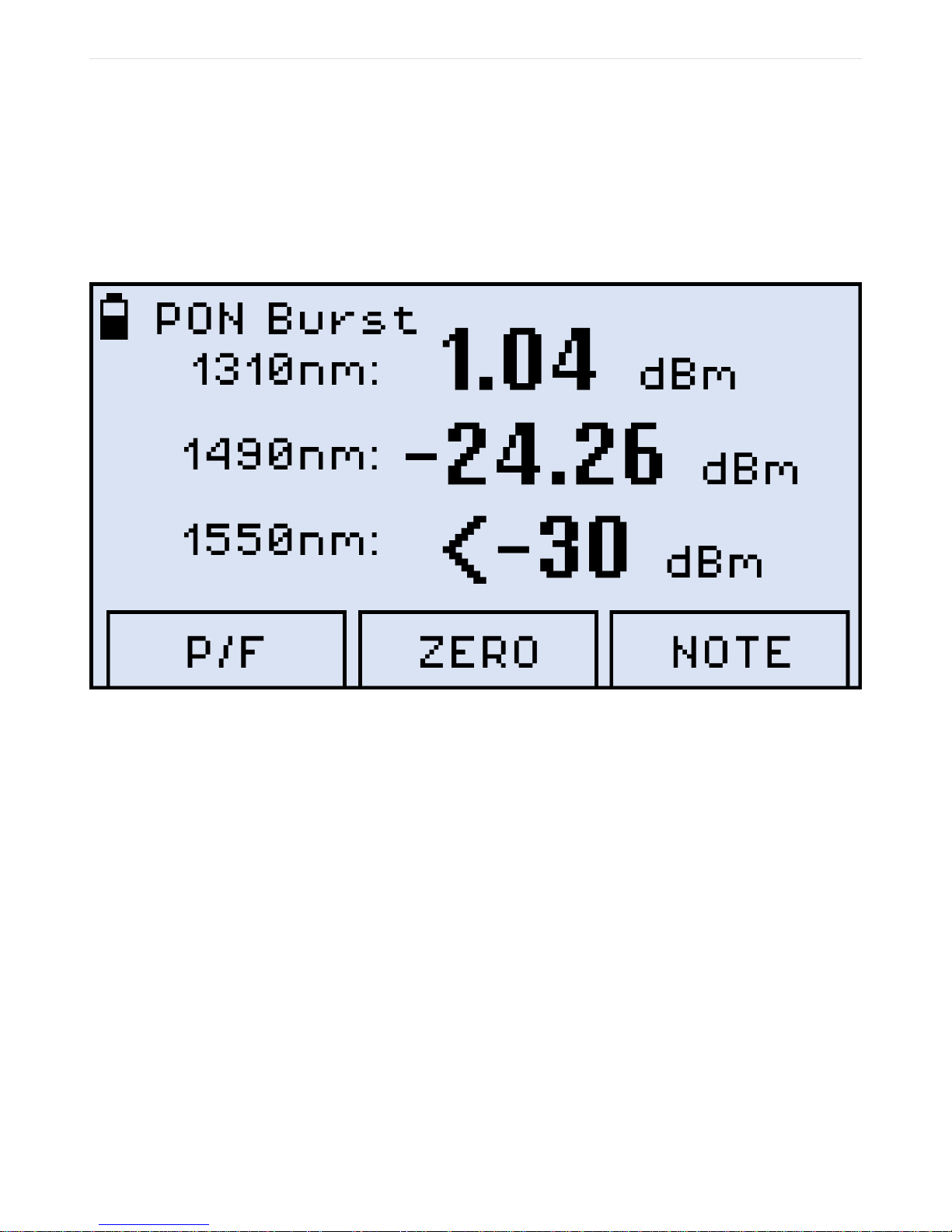
fully operational.) The measurement results are then shown on the screen (the example
below shows typical values one might expect when connected at ONU (location C) and
no P/F thresholds have been set):
Figure 9. PON Burst mode measurement results as values
If P/F thresholds have been set, the measurement results are presented as Pass or Fail (see
an example below):
Page 19
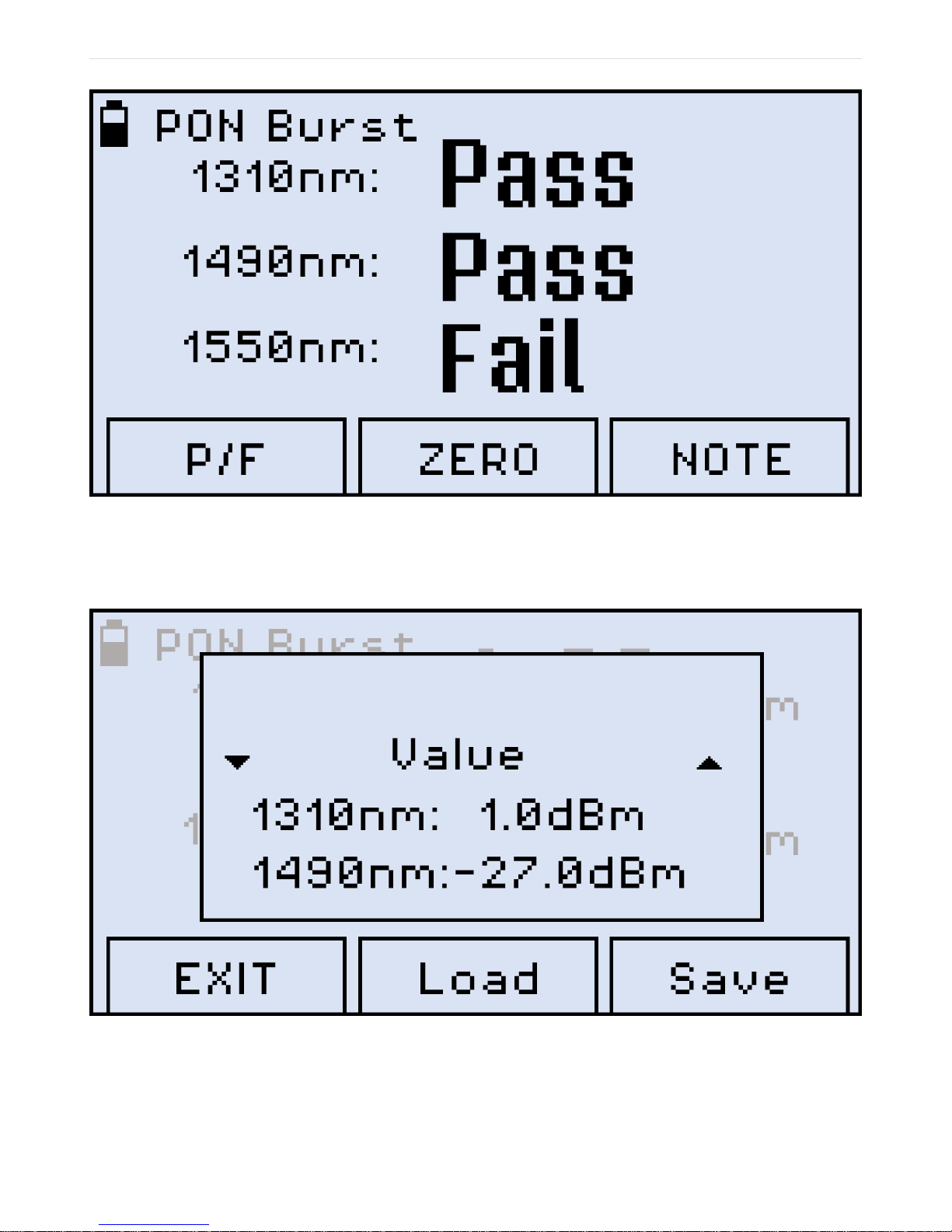
Figure 10. PON Burst mode measurement results as P/F thresholds
FX80 PON User Manual D07-00-115P RevA01
Page 19 of 36
To switch back to actual values for the same measurement, press the |F1| (P/F) button, which
results in the interface shown below:
Figure 11. Switching from thresholds to values for the same measurement
With the Value line selected, press |Shift/Enter| to confirm the selection. The screen then
shows the values for the same measurement.
Page 20
4.2.4. Adding Comments to Measurement Results
FX80 PON User Manual D07-00-115P RevA01
Page 20 of 36
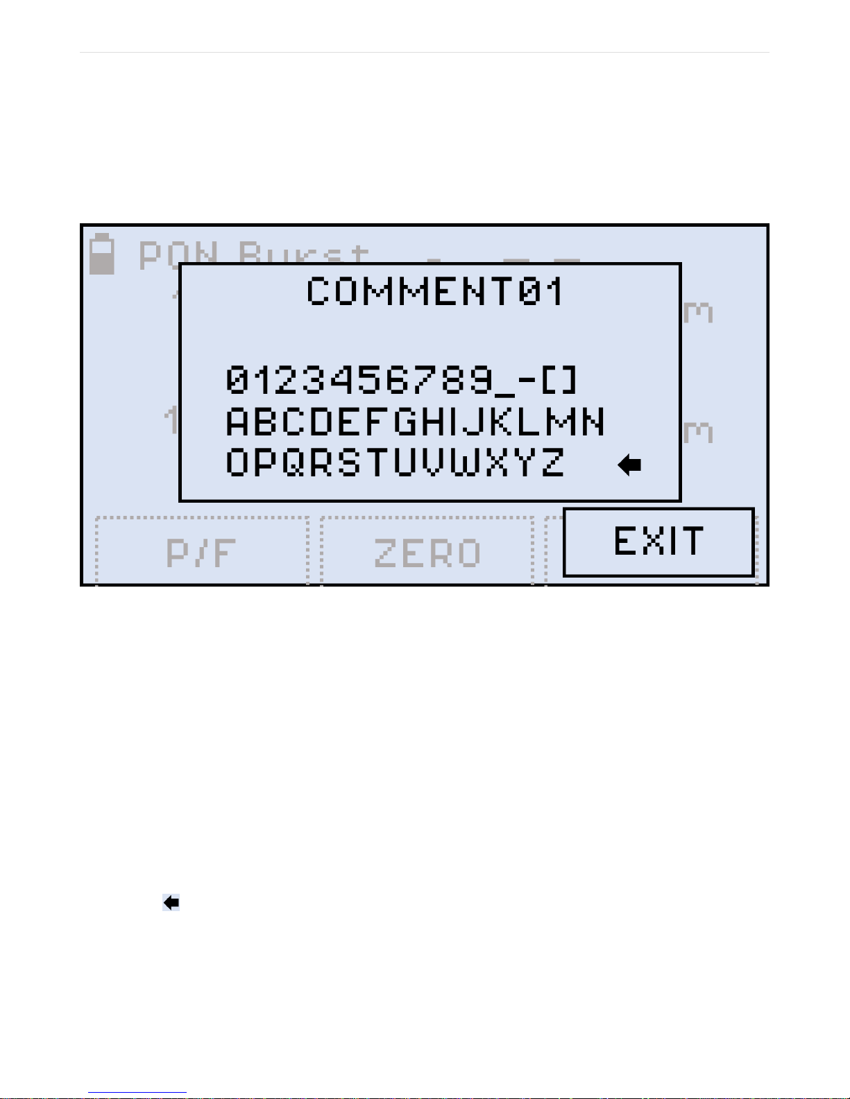
It may be necessary to add a note to your measurement results. To do that, when you are still
in the measuring mode:
1. Press the |F3| (NOTE) button. The result is shown below:
Figure 12. Adding comments to measurement results
2. Press |MODE| until the cursor in the top line starts flashing, then use the |Up| and
|Down| buttons to position the cursor in the line;
3. Press |MODE| again to go to the list of symbols in the lower section. The active symbol
then gets highlighted. Use the |Up| and |Down| buttons to select another symbol if
necessary.
4. Press the |Shift/Enter| button to insert the selected symbol from the list into the selected
position in the top line.
5. Press |MODE| to toggle between positioning the cursor in the top line, and selecting a
symbol from the list. Your comment can include up to 10 symbols.
6. To erase a symbol in the note, place the cursor after that symbol, then select the left
arrow ( ) and execute the command by pressing the |Shift/Enter| button.
7. To save the note and exit the NOTE mode, press the |F3| (EXIT) button.
To save the current measurement results with the current note, press the |Shift/Enter|+|Up|
button combination (Save). The Saved notification is then briefly shown onscreen, and your
Page 21
current measurement results with the current note are saved in the device memory.
FX80 PON User Manual D07-00-115P RevA01
Page 21 of 36
If you do not save a note for your measurement results, the note from your previous
measurement is used, with the incremented number at the end. This feature may come
handy when you measure several fibers within one batch or one splitter.
Once the note is saved with your measurement results, it cannot be edited.
4.3. Broadband Power Measurements (Optional)
The Broadband OPM is an InGaAs detector with a wavelength range from 800 to 1700nm.
The displayed power readings can be absolute (dBm and watts) or relative (dB). To measure
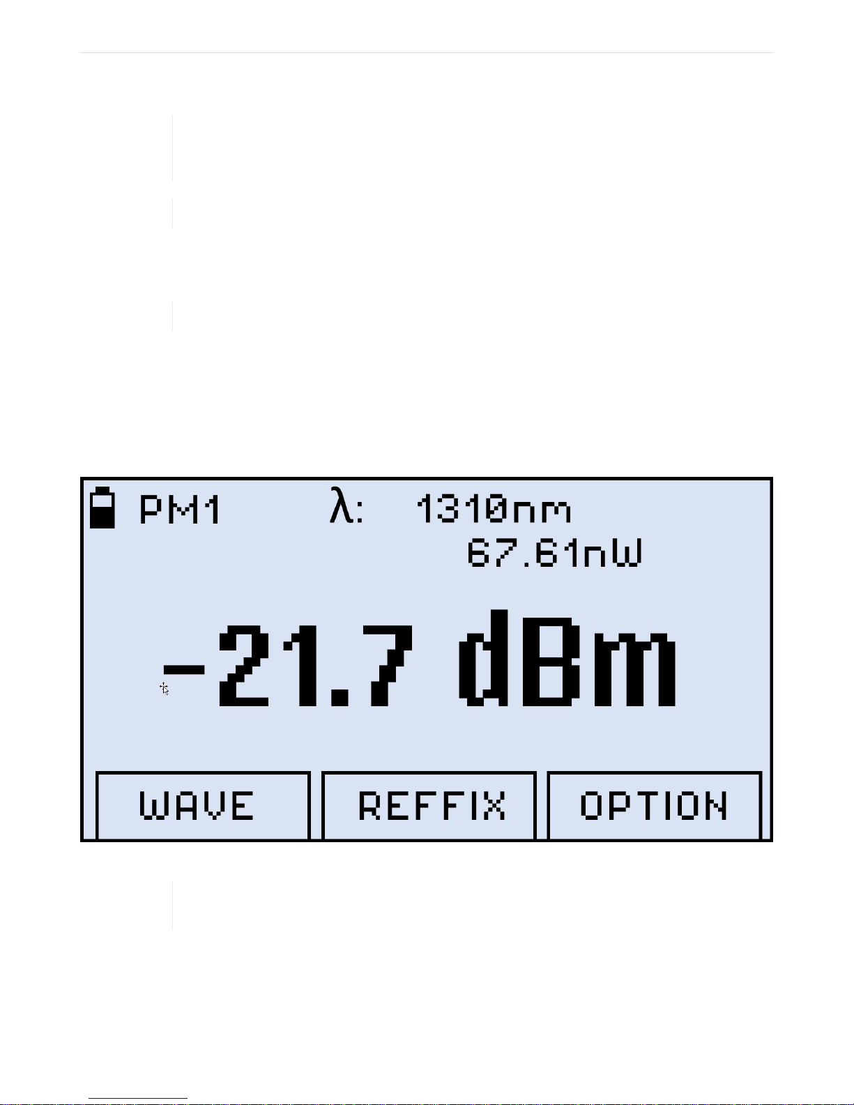
the optical power in a fiber, insert the test fiber on the OPM test port and press |MODE| until
the PM1 or PM2 test mode appears at the upper left corner of the display (the Figure below
Results of PM measurement is an example of PM1 measurement result).
Clean the fiber before connecting it to the device.
The fiber under test must have only one wavelength. If there are several wavelengths, the
To change the wavelength, press the |F1| button (WAVE). The resulting calibrated wavelength
list is then shown below:
measurement results will NOT be valid.
Figure 13. Results of PM measurement
Page 22
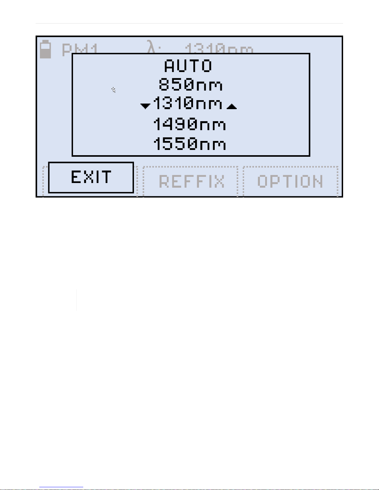
Figure 14. Selecting a wavelenght for PM measurement
FX80 PON User Manual D07-00-115P RevA01
Page 22 of 36
Select a wavelength by pressing the |Up| and |Down| buttons, then press the |Shift/Enter|
button to confirm your choice. The new wavelength then appears in the top right corner of the
display. If you select a wavelength and then press the |F1| button (EXIT), the previous
wavelength remains effective.
If your fiber under test carries a signal with WaveID details, you can select [ AUTO ]. Then
your FX80 determines the wavelength automatically.
If you have selected the [ AUTO ] option for a signal without WaveID or modulated, the λ
value goes blank, and the measurement results are NOT valid.
4.3.1. Setting Power Reference Level
To measure the fiber under test span loss, first set a reference level for each test wavelength.
For that press the |F3| button (OPTION). The resulting screen is shown below:
Page 23
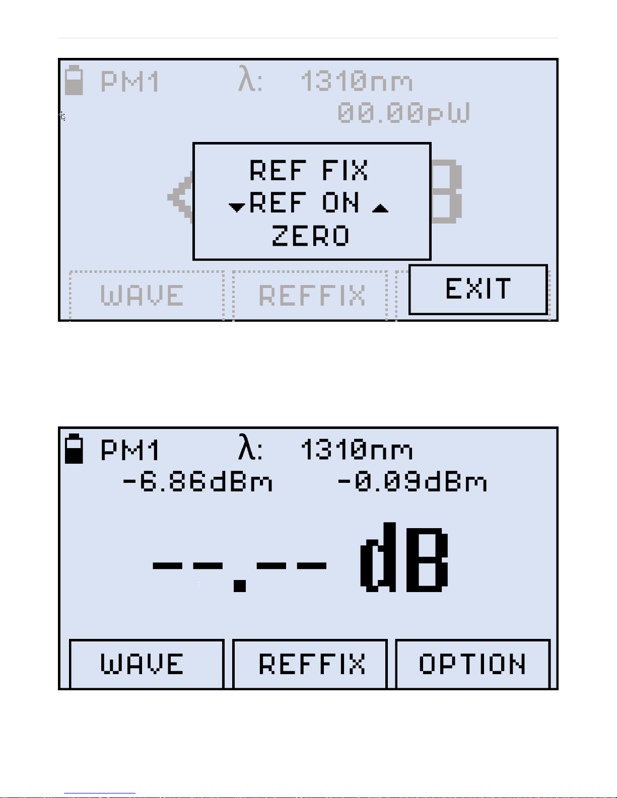
Figure 15. Selecting a reference option for PM measurement
FX80 PON User Manual D07-00-115P RevA01
Page 23 of 36
• REF FIX command: sets the current power value as the reference level. To do that, make
sure the cursor is at REF FIX and press the |Shift/Enter| button. As a result, the value
onscreen changes to --.--dB (see the Figure below Current power value set as the
reference level).
Figure 16. Current power value set as the reference level
Page 24
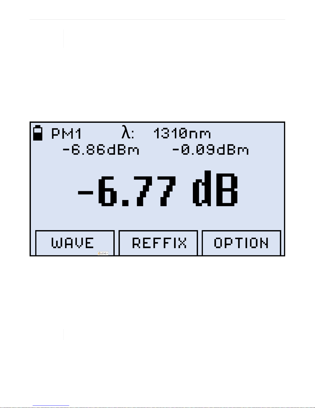
The current reference level value is shown at the second row on the left (-6.86dBm in the
FX80 PON User Manual D07-00-115P RevA01
Page 24 of 36
• REF OFF command: makes the previously stored reference level inactive. The
measurement result is then shown in dBm. After you select this option, its name changes
onscreen to [ REF ON ].
• REF ON command: makes the previously stored reference level active. To make the
current optical power the reference level, first select [ REF FIX ], then [ REF ON ]. The
measurement result is then shown in dB (see an example below). After you select this
option, its name changes onscreen to [ REF OFF ].
example above).
Figure 17. Broadband measurement taken against a reference level
• ZERO command: calibrates the ZERO level for the device.
4.4. Visual Fault Locator (VFL)
Your FX80 can be equipped with a Visual Fault Locator (VFL). To test a fiber line for
continuity, connect the fiber to the VFL port.
After that press the |MODE| button until you get the VFL mode (see the Figure Starting VFL
mode below).
Clean the fiber before connecting it to the device.
Page 25
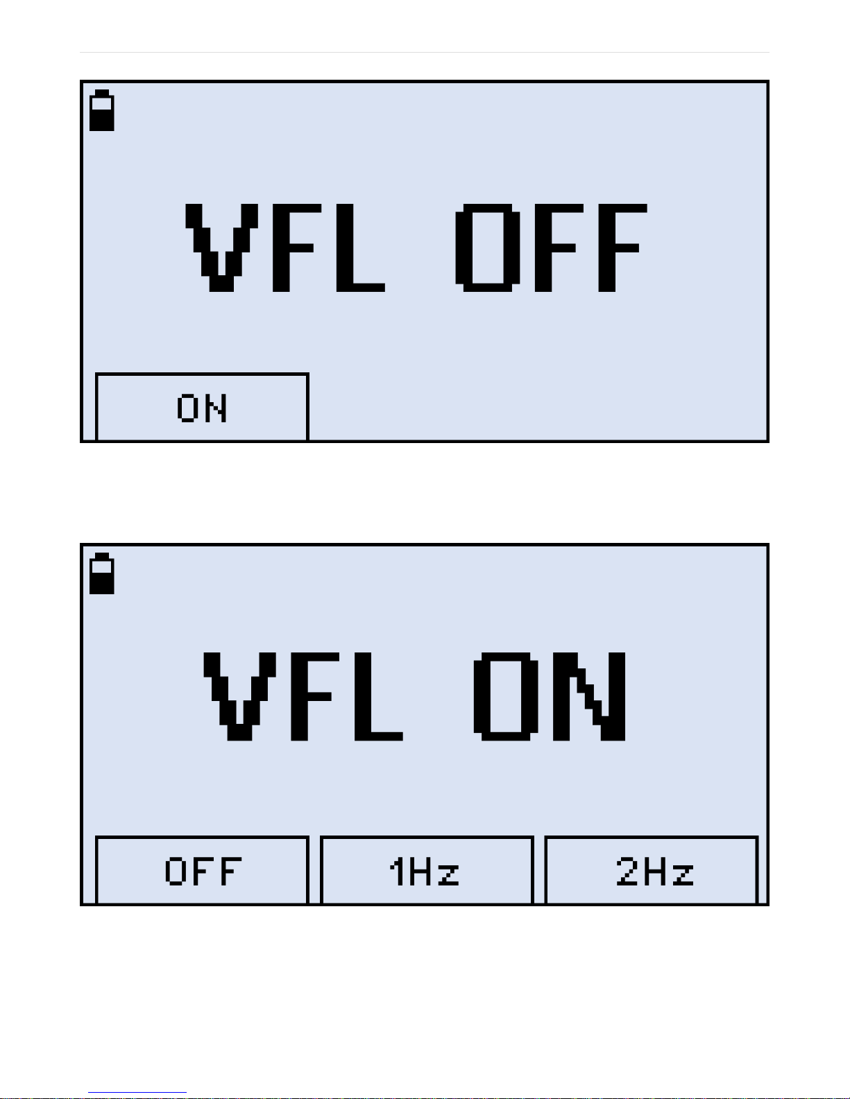
Figure 18. Starting VFL mode
FX80 PON User Manual D07-00-115P RevA01
Page 25 of 36
To start testing your fiber line for continuity, press the |F1| (ON) button. The result is shown
below:
Figure 19. Starting VFL testing, continuous light
To modulate the light (1 or 2 Hz), press |F2| (1Hz) or |F3| (2Hz) respectively. The pressed
button then changes to CONT, and your can press it to return to continuous light (see an
example below).
Page 26
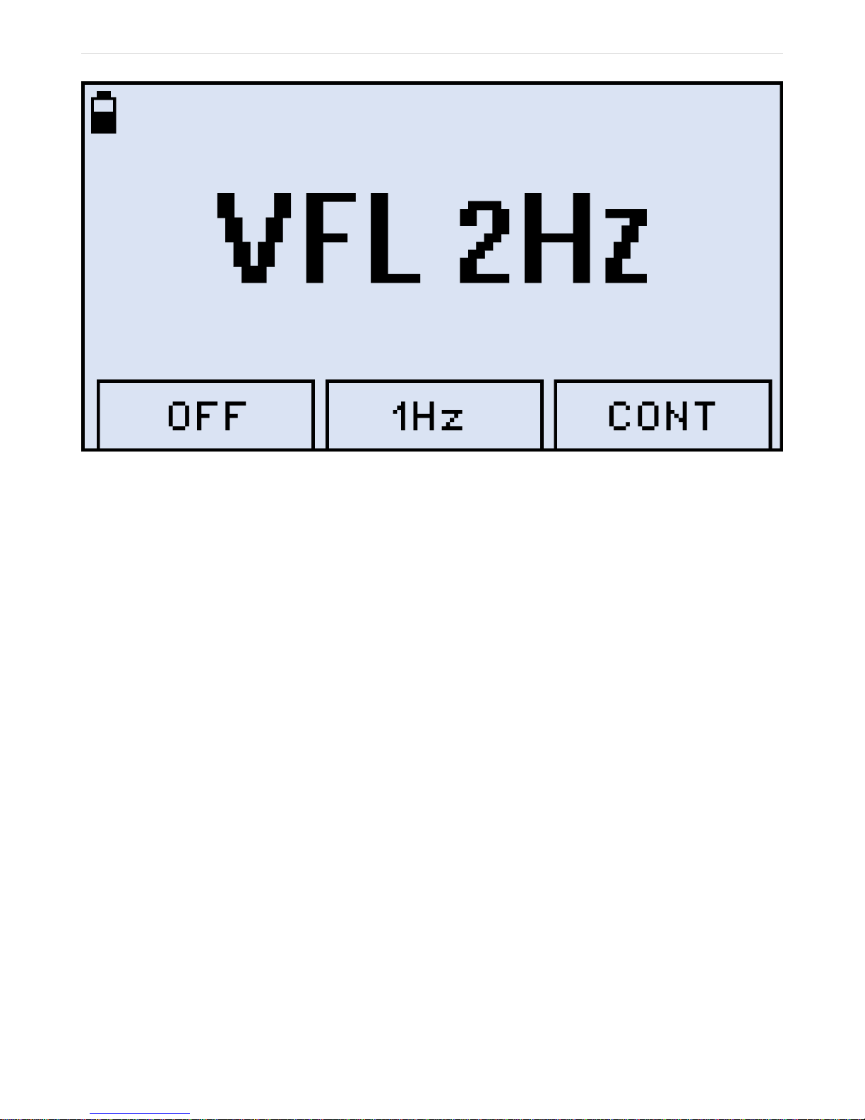
Figure 20. VFL testing, modulated light
FX80 PON User Manual D07-00-115P RevA01
Page 26 of 36
To go to another mode from the VFL mode, press the |MODE| button.
Page 27

5. Downloading Measurement Results to
FX80 PON User Manual D07-00-115P RevA01
Page 27 of 36
PC
To transfer test results and create a measurement report, you will first need to install the
LTSync PC software which is available as a standalone program or part of the Fiberizer
Expert package.
5.1. Installing the FX40/45/80 USB driver
For your PC to work with the FX80 device, you need to install the FX40/45/80 USB driver:
1. Plug in the FX80 device to your PC via the supplied USB - microUSB cable. If you check
your Windows Device Manager then, you see the FX80 item in the Other devices list.
The FX80 item is shown with the exclamation mark sign (see an example below)
meaning that the driver for the device is not installed;
2. Download the driver from the VeEX official web site at www.veexinc.com;
3. Go to your Windows Device Manager and righ-click the FX80 item, then select Update
driver (see an example below);
Page 28
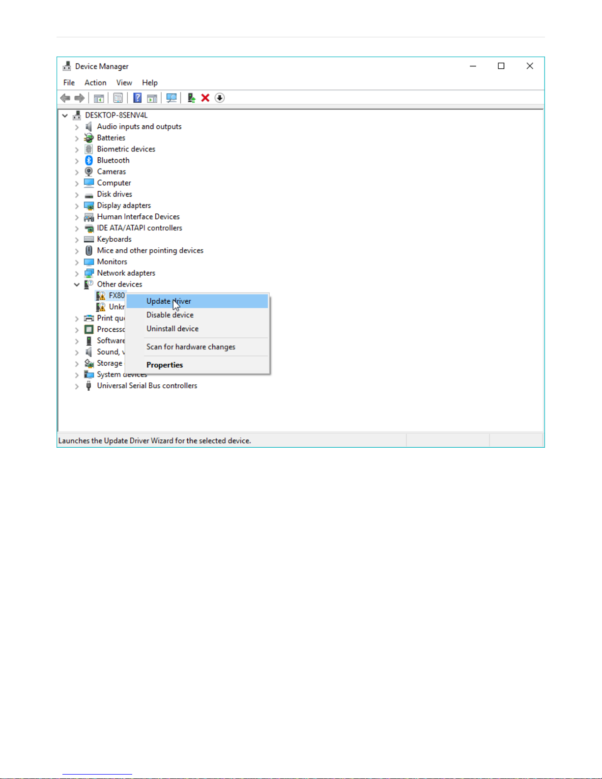
Figure 21. Installing the driver for FX80
FX80 PON User Manual D07-00-115P RevA01
Page 28 of 36
4. In the window which appears next select Browse my computer for driver software,
then define the path where you previously saved the downloaded driver, and click
[ Next ]. The driver installation starts, and after a while you are notified about the driver
has been updated (installed) successfully (see below).
Page 29
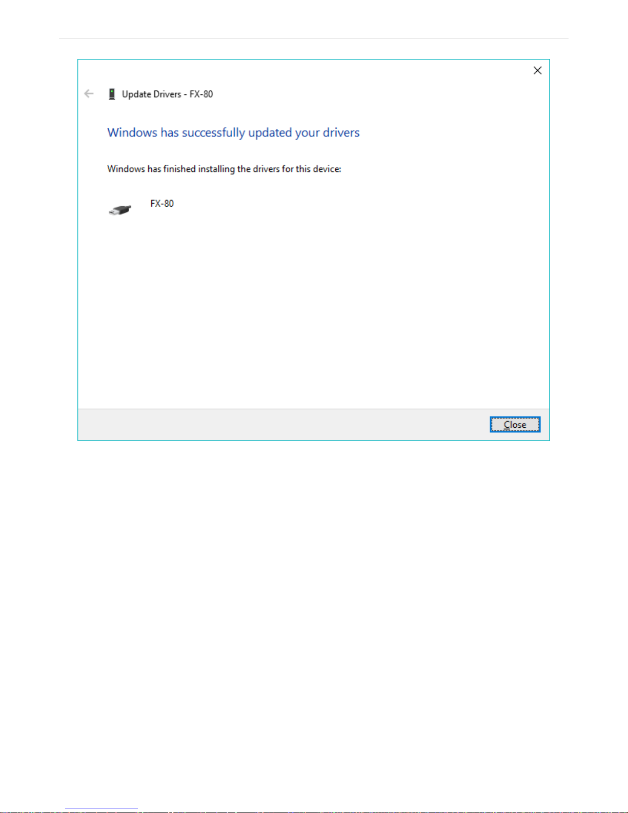
Figure 22. The driver for FX80 successfully installed
FX80 PON User Manual D07-00-115P RevA01
Page 29 of 36
Now your PC is ready to work with the FX80 device.
5.2. Transferring measurement results to PC
To transfer measurement results to the PC:
1. Launch LTSync and connect your FX80 to the PC via the micro-USB cable provided.
The resulting window is shown below, with the device and its serial number recognized
by the program.
Page 30
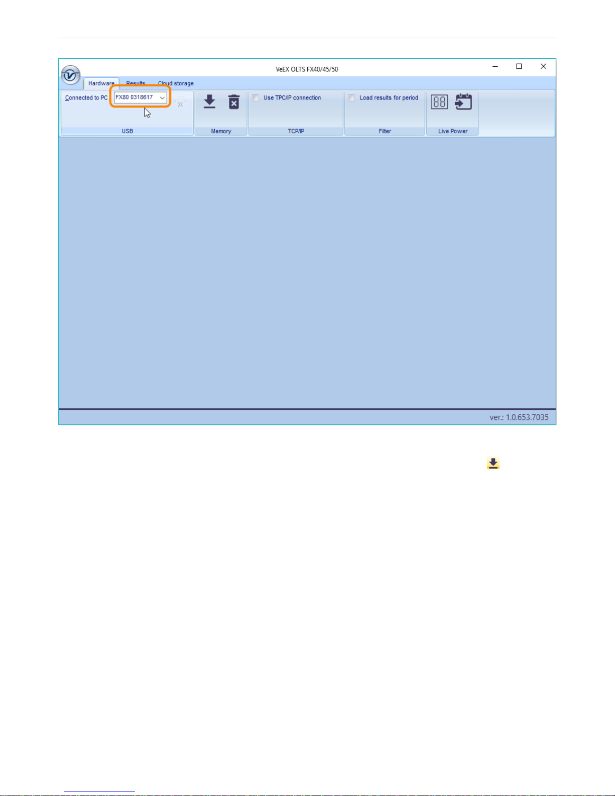
Figure 23. FX80 is connected to PC in LTSync, its serial number is recognized by the program
FX80 PON User Manual D07-00-115P RevA01
Page 30 of 36
2. To view the measurement results on the PC, click the [ Download ] button ( , see it, for
example, in the Figure below Measurement results are presented as a table). The
measurement results presented in a tabular form. Use the scroll bar to view all results.
Page 31
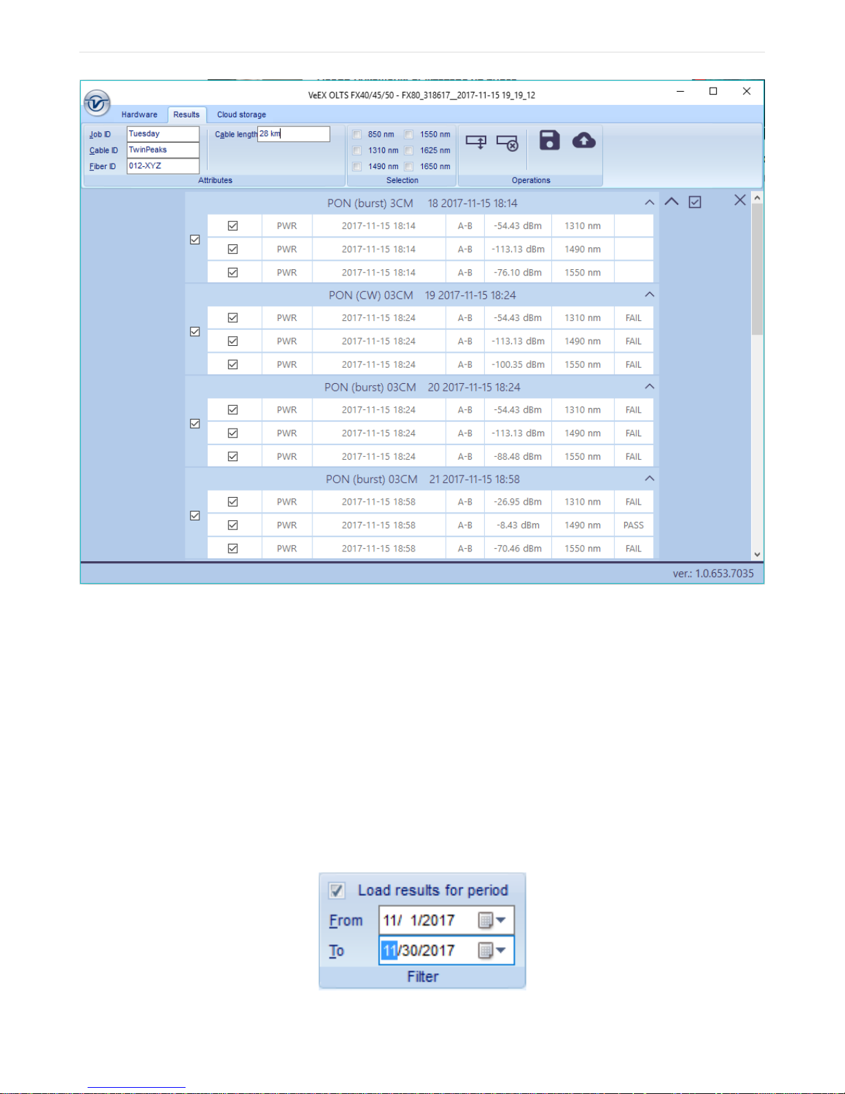
Figure 24. Measurement results are presented as a table
FX80 PON User Manual D07-00-115P RevA01
Page 31 of 36
3. To prepare your measurement results for a report, enter the pertinent information into the
fields in the Attributes section (see, for example, the Figure above Measurement results
are presented as a table).
The displayed results can be filtered by the test group and/or wavelength by selecting the
desired results that you wish to work with in the main viewing area (see, for example, the
Figure above Measurement results are presented as a table).
To download results of a certain period of time, go to the Hardware tab and select the [ Load
results for period ] checkbox. This brings (see the Figure below Filtering measurement
results by time).
Figure 25. Filtering measurement results by time
Page 32

To delete a row of results, select its checkbox and then click the [ Delete row ] button ( , see
FX80 PON User Manual D07-00-115P RevA01
Page 32 of 36
it, for example, in the Figure above Measurement results are presented as a table). You can
also select several rows of test results and delete them all at the same time.
To move a row to another group, highlight the row by clicking it, after which the border around
the row will turn orange. You can now drag-and-drop this row to another group. Alternatively,
you can highlight the row, then click the [ Move row ] button ( , see it, for example, in the
Figure above Measurement results are presented as a table), then highlight the desired
group.
To save the measurement results to your PC, click the [ Save to PC ] button ( , see it, for
example, in the above Figure Filtering measurement results by time).
To erase all test results from the FX80 memory, go to the Hardware tab and click the [ Erase
all memory ] button ( ).
You can move only one row at a time.
You can move a row to another group only if there is no measurement with that
wavelength in the group.
6. Uploading Measurement Results to
Fiberizer Cloud
You can access your Fiberizer Cloud account within the LTSync program. To do this, go to
the Cloud storage tab and click the [ Log in to Fiberizer Cloud ] button ( ), then enter your
credentials in the resulting form.
If you do not have a Fiberizer Cloud account, click the [ Register in Fiberizer Cloud ] button
( ), then register there.
To upload your measurement results to Fiberizer Cloud, go to the Results tab and click the
[ Upload to Fiberizer Cloud ] button ( ). Then LTSync creates a folder in your Fiberizer
Cloud account named after the connected device (for example, FX80 7654321) and uploads
your measurement results into this folder.
To log out from your Fiberizer Cloud account, click the [ Log out from Fiberizer Cloud ]
button ( ).
Page 33

Warranty and Software
FX80 PON User Manual D07-00-115P RevA01
Page 33 of 36
Warranty Period: The warranty period for hardware, software and firmware is one (1) year
from the date of shipment to the customer. This warranty period is limited to manufacturing
defects. Accessories such as patchcords, dust covers, carrying case, carrying pouch, etc.
have a 90-day warranty period.
Hardware Coverage: VeEX Inc. warrants hardware products against defects in materials and
workmanship. During the warranty period, VeEX will, at its sole discretion, either
• Repair the products, or
• Replace hardware which proves to be detective provided.
Products under warranty must be returned to VeEX Inc. for assessment by the customer
along with the proof of purchase within thirty (30) days of the request by the customer, freight
prepaid.
Software Coverage: VeEX Inc. warrants software and firmware materials against defects in
materials and workmanship. During the warranty period, VeEX will, at its sole discretion,
either
• Upgrade the firmware if required. For this the customer may have to return the unit to the
Service center.
• Provide new software for the user to upgrade.
The customer may elect to return the unit to VeEX Inc. along with the proof of purchase within
thirty (30) days of the request by the customer, freight prepaid.
Additionally, during the warranty period, VeEX Inc. will provide, without charge to the
customer, all fixes, patches and enhancements to the purchased software, firmware and
software options. VeEX Inc. does not warrant that all software or firmware defects will be
corrected. New enhancements attached to a software option require the option to be
purchased (at the time of order or the time of upgrade) in order to benefit from such
enhancements.
Limitations: The warranty is only for the benefit of the customer and not for the benefit of any
subsequent purchaser or licensee of any merchandise (hardware, software, firmware and/or
accessories).
Revoking the warranty: VeEX Inc. does not guarantee or warrant that the operation of the
hardware, software or firmware will be uninterrupted or error-free. The warranty will not apply
in any of the following cases:
Page 34

• Improper or inadequate maintenance by the customer;
FX80 PON User Manual D07-00-115P RevA01
Page 34 of 36
• Damage due to software installed by the customer on the unit without prior written
authorization from VeEX Inc;
• Unauthorized alteration or misuse;
• Damage occurred from operating the unit from outside of the environmental
specifications for the product;
• Improper installation by the customer.
Page 35

Appendix A: Optical Specifications
FX80 PON User Manual D07-00-115P RevA01
Page 35 of 36
Table 2. PON Power Meter
Calibrated wavelengths (nm) 1310/1490/1550
Number of test ports 2 (ONU, OLT)
Continuous data measurement range (dBm)
1310 nm -40 to +10
1490 nm -40 to +12
1550 nm -40 to +25
Burst data measurement range (dBm) – OLT to ONT
1310 nm -30 to +10
Spectral Passband (nm)
1310 nm 1260 to 1360
1490 nm 1470 to 1505
1550 nm 1535 to 1570
Power measurement accuracy, (dB) ± 0.5
Pass-Through Insertion Loss, (dB) < 1.5
Linearity, (dB) ± 0.1
Display Resolution (dB) 0.01
Results dBm, W, dB, Pass/Fail
Interface Fixed APC
Connector Type SC
User Defined Thresholds 1 set
Internal memory capacity > 1,000 results with timestamp
Page 36
Table 3. Broadband Power Meter (Optonal)
FX80 PON User Manual D07-00-115P RevA01
Page 36 of 36
Wavelength range (nm) 850 to 1650
Calibrated wavelengths (nm) 1310/1490/1550/1625/1650
Power measurement range (dBm)
Standard (PM1) -65 to +10
High (PM2) -50 to +25
Power measurement accuracy %, (dB) ± 5, (0.22)
Tone detection 270 Hz, 1 KHz, 2 KHz
Wave ID Compatible with VeEX Light source
Optical adaptors (interchangeable) SC, FC, LC, Universal 1.25 & 2.5 mm
Table 4. Other Technical Parameters
Dimensions 129 x 61 x 38 mm
Weight <0.4 kg
Protection Rugged, 1 meter drop tested
Battery Li-Ion 3100 mAh
Power Supply Micro USB interface, 5 VDC charger
Connection with PC Micro USB, data transfer via PC software
Display Graphical, w/b, high-contrast
Operating Temp -10 °C to +50 °C
Storage Temp -20 °C to +70 °C
Humidity 0% to 95%, non-condensing
 Loading...