

VeEX FX150, MTTplus-410, FX300, RXT-4100, TX300s User Manual
...
OTDR Series e-Manual, D07-00-076P-RevC00 Page 1 of 107
OTDR Series e-Manual, D07-00-076P-RevC00 Page 1 of 107
• FX150
• FX300
• MTTplus-410
• RXT-4100
• TX300s
OTDR Series

OTDR Series e-Manual, D07-00-076P-RevC00 Page 2 of 107
Table of Contents
1.0 ABOUT THIS USER MANUAL ..................................................................................... 5
2.0 PRODUCT INTRODUCTION ........................................................................................ 6
2.1 PLATFORM HIGHLIGHTS (FX150/FX300/MTTPLUS/RXT/TX300S) .............................................. 6
2.2 KEY FEATURES .......................................................................................................................... 7
2.3 PACKAGE CONTENTS ................................................................................................................. 8
3.0 SAFETY INFORMATION .............................................................................................. 9
4.0 THEORY OF OPERATION ......................................................................................... 10
4.1 OTDR ...................................................................................................................................... 10
4.2 LIGHT SOURCE ......................................................................................................................... 11
4.3 OPTICAL POWER METER .......................................................................................................... 11
4.4 VISUAL FAULT LOCATOR .......................................................................................................... 11
5.0 BASIC OPERATION ................................................................................................... 12
5.1 TEST PORTS AND INTERFACES ................................................................................................. 12
5.2 FRONT PANEL LAYOUT ............................................................................................................. 14
5.2.1 LED Indicators ...................................................................................................................................... 14
5.2.2 Rubber Keypad ..................................................................................................................................... 14
5.2.3 Menu Navigation .................................................................................................................................. 15
5.3 MTTPLUS OVERVIEW ............................................................................................................... 16
5.3.1 MTTplus Side View ............................................................................................................................... 16
5.3.2 MTTplus Control Panel ........................................................................................................................ 17
5.3.3 MTTplus OTDR Module Top View ....................................................................................................... 17
5.4 RXT OVERVIEW ........................................................................................................................ 18
5.4.1 RxT Front Panel .................................................................................................................................... 19
5.4.2 Getting Started ..................................................................................................................................... 20
5.5 FX150 OVERVIEW .................................................................................................................... 21
5.5.1 FX150 Test Ports .................................................................................................................................. 21
5.5.2 FX150 Keypad ....................................................................................................................................... 21
5.5.3 FX150 Screen Navigation .................................................................................................................... 22
5.5.3.1 View/Hide side menu panels ......................................................................................................... 23
5.5.4 Setting up FX150 WiFi ......................................................................................................................... 24
5.5.4.1 Access WiFi option ........................................................................................................................ 24
5.5.4.2 Connect to a WiFi network ............................................................................................................ 25
5.6 CUSTOMIZING YOUR TESTER .................................................................................................... 26
6.0 TEST FIBER AND INITIAL PREPARATION INTRODUCTION ................................. 28
6.1 CONTAMINATION ...................................................................................................................... 29
6.2 INSPECTION .............................................................................................................................. 29
6.3 CLEANING PROCEDURE ............................................................................................................ 30
6.4 BEST PRACTICES ..................................................................................................................... 31
6.5 CONNECTORS .......................................................................................................................... 32
6.5.1 Connector Types .................................................................................................................................. 32
6.5.2 Connector Performance and Polishing .............................................................................................. 34
6.6 FIBER CABLES AND FIBER PATCHCORDS .................................................................................. 36
6.6.1 Fiber Cable ............................................................................................................................................ 36
6.6.2 Fiber Patchcord .................................................................................................................................... 37
6.7 INSERTING THE FIBER ............................................................................................................... 39
6.7.1 Preventing Inaccurate Readings ........................................................................................................ 39
6.8 FIBER SCOPE UTILITY (FX150, FX300, MTTPLUS, RXT) ........................................................... 39

OTDR Series e-Manual, D07-00-076P-RevC00 Page 3 of 107
6.8.1
Fiber Scope Overview .......................................................................................................................... 39
6.8.2 Connecting the Fiber Scope ............................................................................................................... 40
6.8.3 Setup ..................................................................................................................................................... 41
6.8.4 Analysis ................................................................................................................................................ 41
6.8.5 Capture Screen ..................................................................................................................................... 42
6.8.6 Captured Files ...................................................................................................................................... 43
6.8.7 Connector Face Analysis .................................................................................................................... 44
6.8.8 Connector Face Analysis Results Table ............................................................................................ 45
6.8.8.1 HTML Report ................................................................................................................................. 46
6.8.8.2 PDF Report .................................................................................................................................... 47
6.8.9 Managing Fiberscope Results with File Manager ............................................................................. 48
6.8.9.1 File Manager Filters ....................................................................................................................... 49
6.8.10 Fiber Scope Image Management Software (ViS400D only) ......................................................... 50
6.8.11 Fiber Scope Image Management Software (VS-500 and DI-1000 only) ....................................... 51
6.9 VISUAL FAULT LOCATOR (VFL) ................................................................................................ 54
6.9.1 Using the VFL ....................................................................................................................................... 55
6.10 OPTICAL LIGHT SOURCE (OLS) ................................................................................................ 56
6.10.1 Accessing and setting up the Optical Light Source ..................................................................... 57
6.10.2 Using the Optical Light Source ...................................................................................................... 58
6.11 OPTICAL POWER METER (OPM) ............................................................................................... 59
6.11.1 Setting up the Optical Power Meter ............................................................................................... 59
6.11.1.1 USB OPM Setup Options .............................................................................................................. 60
6.11.1.2 Setting Pass/Fail Limits ................................................................................................................. 61
6.11.2 Using the built-in OPM .................................................................................................................... 62
6.12 OPTICAL LOSS TEST SET (OLTS) (NOT CURRENTLY SUPPORTED) ............................................. 64
6.13 RESULTS .................................................................................................................................. 64
7.0 WORKING WITH THE OTDR ..................................................................................... 66
7.1 TEST SETUP ............................................................................................................................. 66
7.1.1 Initial Settings ....................................................................................................................................... 66
7.1.2 Manual mode ........................................................................................................................................ 67
7.1.3 Auto mode ............................................................................................................................................ 70
7.1.4 V-Scout mode (optional) ...................................................................................................................... 71
7.1.4.1 Setting up and Using V-Scout mode ............................................................................................. 73
7.1.4.2 V-Scout symbols ............................................................................................................................ 74
7.2 THRESHOLDS ........................................................................................................................... 76
7.2.1 Analysis Thresholds ............................................................................................................................ 76
7.2.2 Pass/Fail Thresholds ........................................................................................................................... 77
7.2.3 Event Table ........................................................................................................................................... 78
7.2.4 Autosave Parameters .......................................................................................................................... 78
7.2.5 Cloud Credentials ................................................................................................................................ 80
7.3 MAKING MEASUREMENTS ......................................................................................................... 81
7.3.1 Trace Display ........................................................................................................................................ 81
7.4 EVENTS .................................................................................................................................... 82
7.4.1 Event Table ........................................................................................................................................... 82
7.4.2 Event Types .......................................................................................................................................... 83
7.4.3 Event Editing ........................................................................................................................................ 83
7.5 MEASURE MODE ...................................................................................................................... 84
7.5.1 Markers Controls .................................................................................................................................. 84
7.5.1.1 Marker Operation ........................................................................................................................... 84
7.5.1.2 Zoom/Scroll Controls ..................................................................................................................... 85
7.5.2 Distance Measurements ...................................................................................................................... 86
7.5.3 Loss Measurements ............................................................................................................................. 86
7.5.3.1 Two Point Loss (2-Pt Loss) ........................................................................................................... 86
7.5.3.2 Two Point LSA (2-Pt LSA) ............................................................................................................. 87
7.5.4 Splice Loss Measurement ................................................................................................................... 87
7.5.5 Reflectance Measurement ................................................................................................................... 88

OTDR Series e-Manual, D07-00-076P-RevC00 Page 4 of 107
7.5.6
ORL Measurement ............................................................................................................................... 89
7.6 TRACES ................................................................................................................................... 90
7.6.1 Trace Properties ................................................................................................................................... 91
7.6.2 Saving OTDR Traces ............................................................................................................................ 93
7.6.3 Saving OTDR Traces with Embedded GPS and Camera Image ...................................................... 94
7.6.3.1 Obtaining GPS Coordinates .......................................................................................................... 94
7.6.4 Adding GPS to OTDR file (optional feature) ...................................................................................... 94
7.6.5 Adding Camera Image OTDR file (MTTplus only) ............................................................................. 95
7.7 RESULTS .................................................................................................................................. 97
7.7.1 File Management .................................................................................................................................. 98
7.7.2 Saving/Printing Traces to PDF/USB/Bluetooth ................................................................................. 99
7.7.3 File Operations ................................................................................................................................... 100
7.8 ABOUT TAB ............................................................................................................................ 101
8.0 REVEAL SOFTWARE .............................................................................................. 102
9.0 WARRANTY AND SOFTWARE ............................................................................... 103
10.0 PRODUCT SPECIFICATIONS ................................................................................. 105
11.0 CERTIFICATIONS AND DECLARATIONS .............................................................. 106
12.0 ABOUT VEEX ........................................................................................................... 107

OTDR Series e-Manual, D07-00-076P-RevC00 Page 5 of 107
1.0 About This User Manual
This user manual is suitable for novice, intermediate, and experienced users and is intended to
help you successfully use the features and capabilities of the FX150, FX300, MTTplus, RXT,
and TX300s OTDR series. It is assumed that the user has basic computer experience and
skills, and is familiar with Optical Fiber, telecommunication concepts, terminology, and safety.
Every effort was made to ensure that the information contained in this user manual is accurate.
Information is subject to change without notice and we accept no responsibility for any errors
or omissions. In case of discrepancy, the web version takes precedence over any printed
literature. The content in this manual may vary from the software version installed in the unit.
© Copyright 2006-2017 VeEX, Inc. All rights reserved.
VeEX, VePAL, Sunrise Telecom, Agizer, Optixsoft, Sunlite, Sunset, RXT, MTT, FX, TX, OPX,
and Fiberizer are trademarks of VeEX, Inc. and/or its affiliates in the USA and certain other
countries. All trademarks or registered trademarks are the property of their respective
companies. No part of this document may be reproduced or transmitted electronically or
otherwise without written permission from VeEX, Inc.
This device uses software either developed by VeEX, Inc. or licensed by VeEX, Inc. from third
parties. The software is confidential and proprietary of VeEX, Inc. The software is protected by
copyright and contains trade secrets of VeEX, Inc. or VeEX's licensors. The purchaser of this
device agrees that it has received a license solely to use the software as embedded in the
device, and the purchaser is prohibited from copying, reverse engineering, decompiling, or
disassembling the software.
For more technical resources, visit the VeEX, Inc. web site at www.veexinc.com.
If you need assistance or have questions related to the use of this product, call or e-mail our
customer care department for customer support. Before contacting our customer care
department, you must have your product serial number and software version ready. Please
provide this number when contacting VeEX customer service.
Customer Care:
Phone: + 1 510 651 0500
E-mail: customercare@veexinc.com
Website: www.veexinc.com

OTDR Series e-Manual, D07-00-076P-RevC00 Page 6 of 107
2.0 Product Introduction
The FX150, FX300, MTTplus, RXT, and TX300s feature an OTDR optimized for the installation
and troubleshooting of FTTx, PON, CATV, Mobile Backhaul, and Metro fiber networks.
2.1 Platform Highlights (FX150/FX300/MTTplus/RXT/TX300s)
• Robust, compact hand-held design for demanding field test environments
• High resolution, TFT color touch-screen viewable in any lighting condition. See the
platform’s datasheet for screen size.
• Fast boot-up time essential for fiber restoration
• Internal data storage varies with model. See the platform’s datasheet for more
information at www.veexinc.com.
• USB-A Host Interface supporting (FX300/MTTplus/RXT/TX300s):
• USB flash drives (not available on FX150)
• Fiber inspection probe connection (FX150 requires OTG cable)
• Bluetooth option available
• 3G UMTS data card support (not available on all models). See the platform’s
datasheet for more information at www.veexinc.com.
• Micro USB interface OTG to support (FX150):
• USB flash drives
• Fiber inspection probes
• Ethernet (10/100T) LAN Interface supporting(FX300/MTTplus/RXT/TX300s):
• Remote control
• Transfer OTDR test data
• Perform software upgrades
• Basic IP testing (Ping, Trace route, Web browser)
• Built-in Wireless and Bluetooth options supporting (FX150 standard;
FX300/MTTplus/RXT optional. See the platform’s datasheet for availability at
www.veexinc.com.):
• Software upgrades and uploading test data via wireless connection
• Pairing applications with Mobile Smartphones and Tablet PCs
• Rechargeable Li-Ion battery with capacity indicator, low voltage alarm and Auto-off
function:
• FX150 platform – 10,000 mAH battery
• FX300/TX300s platform – 5200 mAH battery
• MTTplus platform – 5400 mAH battery
• RXT platform - 8400 mAH battery

OTDR Series e-Manual, D07-00-076P-RevC00 Page 7 of 107
• Continuous operation of > 8 hours per Bellcore TRNWT-001138 (platform dependent)
• ReVeal software to transfer fiber test data, upgrade software and perform remote
control (check with factory on availability)
• Fiberizer Cloud to upload fiber test data
• VeExpress to check/upgrade software and installed options status (not available on
FX300 or FX150)
2.2 Key Features
• FTTx optimized parameters for best dead zones
• Filtered 1625 or 1650 nm OTDR port for in-service measurements
• Live fiber detection with embedded power meter
• Dynamic range up to 50 dB (model dependent)
• Event dead zone < 1m, attenuation dead zone < 4m
• Singlemode wavelength options - 1310, 1490, 1550, 1625 and 1650 nm (CWDM and
DWDM C-band also available)
• Multimode wavelength options - 850 and 1300 nm
• Telcordia SR-4731.sor file formats
• Generate and save traces in sor, pdf or csv format (model dependent)
• Auto mode with automated trace diagnostics, simplified setup and events detection
• Optional V-Scout mode – Intelligent Link Mapping using intuitive icons derived from
multiple test acquisitions
• Markers for distance, attenuation, reflectance and splice loss measurements
• Optional universal interface with interchangeable optical adaptors (SC, ST, FC, LC) for
OTDR port
• Power meter, light source, fiber inspection probe and VFL options
• Remote measurement via USB or WiFi connection using Fiberizer Desktop software

OTDR Series e-Manual, D07-00-076P-RevC00 Page 8 of 107
2.3 Package Contents
• OTDR (FX300, FX150, TX300S OTDR blade, RXT-4100 module or MTTplus-410
module)
• AC/DC adaptor
• Input: 100-240 VAC (50/60 Hz), 1.5A max - (MTTPLUS: 5.3A max; FX150: 1.5A
max)
• Output: 16VDC - (MTTPLUS: 15VDC; FX150: 12VDC)
• Ethernet cable (FX300, TX300S OTDR blade, RXT module or MTTplus module)
• Li-Ion battery (capacity depends on platform)
• USB memory stick or CD-ROM containing:
• OTDR Users’ Manual (pdf)
• Reveal and Fiberizer Desktop software
• Software Upgrade Instructions
• Nylon Soft Carry case
OTDR Series e-Manual, D07-00-076P-RevC00 Page 9 of 107
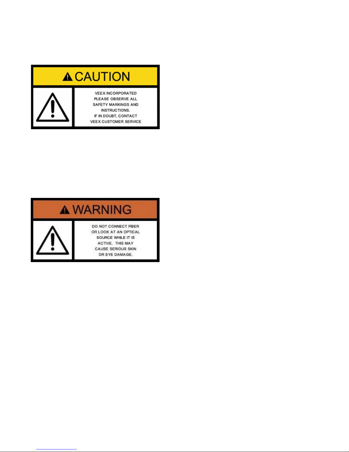
3.0 Safety Information
Safety precautions should be observed during all phases of operation of this instrument. The
instrument has been designed to ensure safe operation however please observe all safety
markings and instructions. Do not operate the instrument in the presence of flammable gases
or fumes or any other combustible environment. VeEX Inc. assumes no liability for the
customer's failure to comply with safety precautions and requirements.
Optical Connectors
The test platform displays a laser warning icon when the laser source is active to alert the user
about a potentially dangerous situation. Make sure that optical sources are inactive before
connecting fiber to the test set to avoid skin or eye damage, or damage to the unit. It is
recommended to:
• Deactivate the laser before connecting or disconnecting optical cables or patchcords.
• Never look directly into an optical patchcord or an optical interface (e.g. CFP, CFP2,
CFP4, QSFP+, SFP+, SFP, OTDR, LS, VFL) while the laser is enabled. Even though
optical transceivers are typically fitted with Class 1 lasers, which are considered eye
safe, optical radiation for an extended period can cause irreparable damage to the eyes.
• Never use a fiber microscope to check the optical connectors when the laser source is
active.
Electrical Connectors
Telephone lines may carry dangerous voltages. Always connect the electrical test ports to
known test interfaces which carry low level signals.
OTDR Series e-Manual, D07-00-076P-RevC00 Page 10 of 107
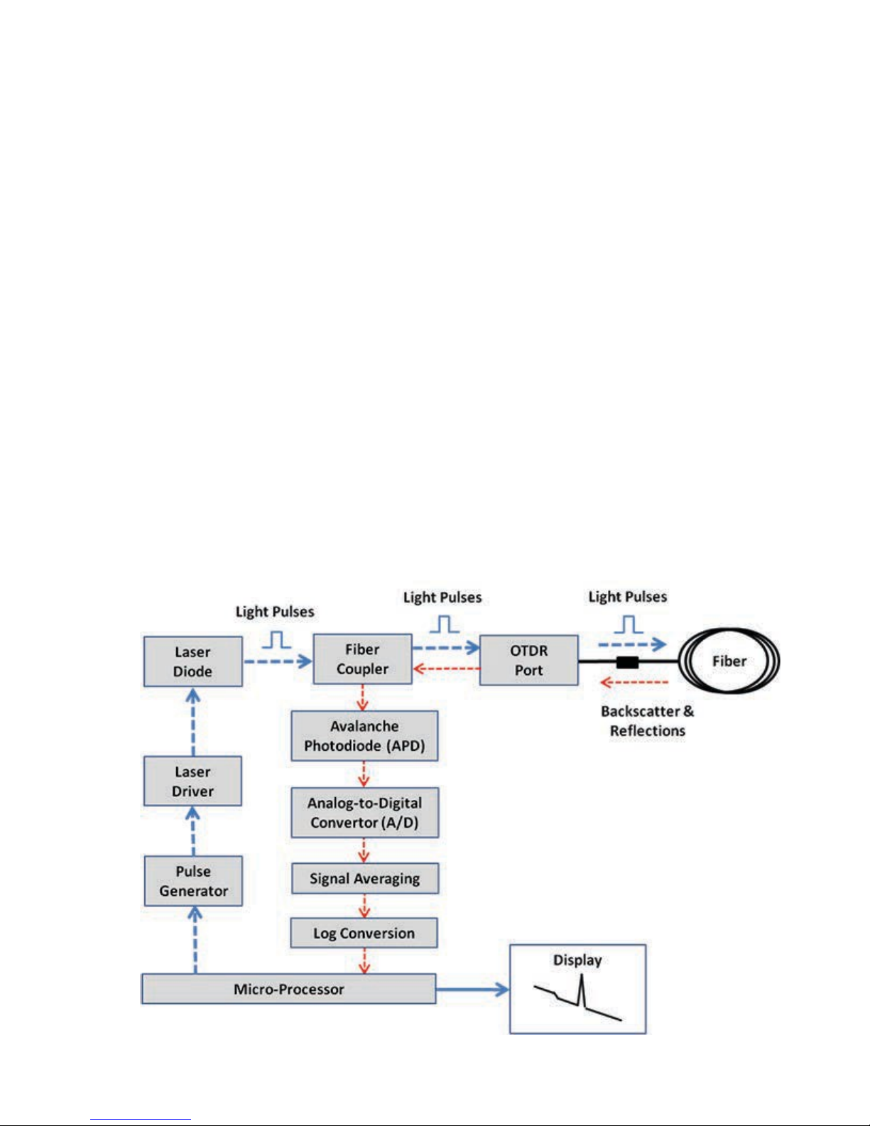
4.0 Theory of Operation
4.1 OTDR
The principle of OTDR operation is based on measuring the Rayleigh back scattering signal
when a single powerful optical pulse passes through an optical fiber. The weak back scattering
signal is registered by an optical receiver, converted into digital form and averaged many
times.
The OTDR calculate distance with next formula:
Distance = c * t / (2 * n)
where c – light speed in vacuum, n – optical fiber index of refraction, t – time
delay between pulse emit and it
registration by receiver
Each sample converted by ADC into digital form is registered in the RAM. To measure the
back-scattering signal precisely, repeated triggering optical pulses is performed. The processor
averages samples, corresponding to the same points of the optical fiber that leads to the
increasing signal-noise ratio. After several cycles, the obtained signal values are transferred
from RAM and displayed. Then, the process of measuring, averaging, and cleaning RAM
registers is repeated again.
OTDR – Principle of Operation

OTDR Series e-Manual, D07-00-076P-RevC00 Page 11 of 107
4.2 Light Source
An optional light source is available and designed for generating continuous optical radiation.
The light source output is the same as the OTDR port and uses the same laser diodes and
optical splitter. The radiation power is stabilized with the help of external photodiode and power
stabilization circuit.
The light source has two operation modes: Continuous and Modulated/tone (270, 1000 and
2000Hz).
The average power at modulation mode is 2 times lower (3dB) than in continuous mode of
operation.
4.3 Optical Power Meter
The OPM is equipped with an InGaAs photodiode (1mm diameter) to measure optical power.
For standard power PM1 measurement range (+10dBm), radiation falls directly on the
photodiode. The OPM will support both MM and SM fiber with the APC or UPC connector type.
For extended measurement PM2 range (+25dBm), an integrating sphere with a photodiode is
used. Input power is attenuated by the integrating sphere by approximately 100 times.
The current of the photodiode is amplified and converted into digital form with the help of
analog-digital converter. The received digital signal is processed by microprocessor and the
value of the measured optical power is displayed.
4.4 Visual Fault Locator
The unit is equipped with an optional Visual Light Locator (VFL) to visually identify breaks in
the fiber typically hidden in the OTDR dead zone.
• Output power: 0 dBm (Typical)
• Operation modes: Continuous wave (CW) or 2Hz modulation
OTDR Series e-Manual, D07-00-076P-RevC00 Page 12 of 107
5.0 Basic Operation
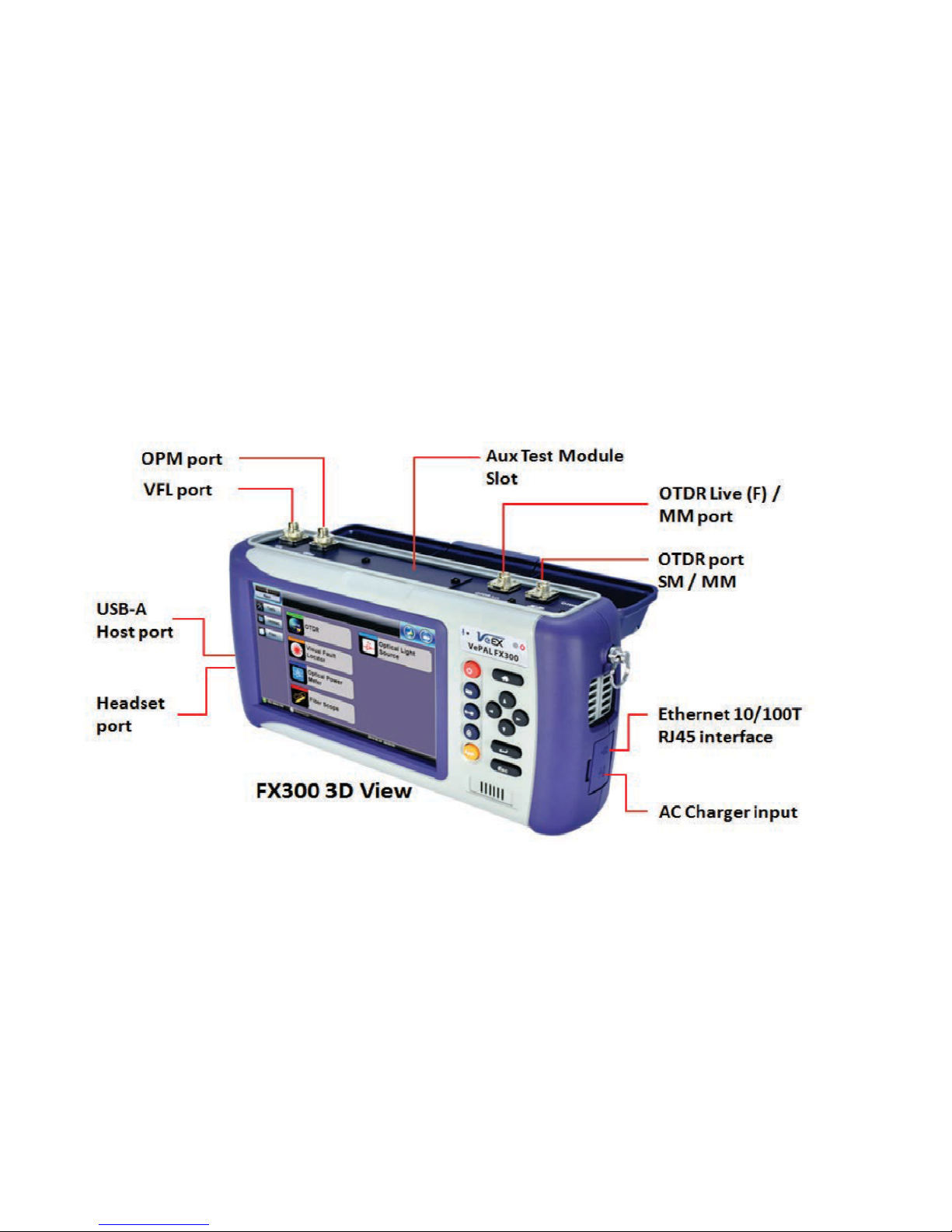
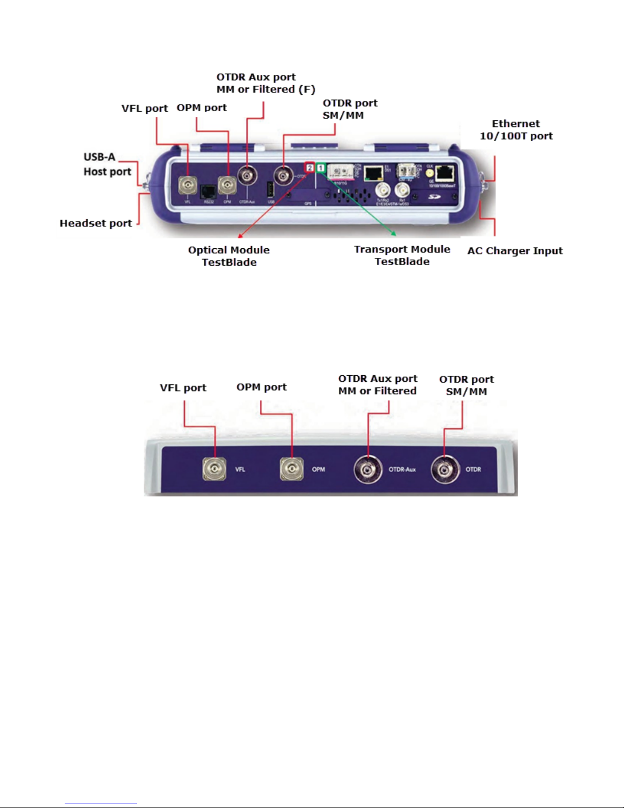
5.1 Test Ports and Interfaces
OTDR testing: The optical fiber under test is connected to either the OTDR or OTDR Aux
(Filtered SM or MM) port on the top panel. The type of the optical fiber connector must
correspond to the OTDR connector or adaptor type, including the connector polish.
Optical Power Meter (OPM) testing: The optical fiber is connected to the OPM port on the
top panel. Depending on fiber connector type, use interchangeable adaptors. FC, SC, ST or
LC type are supplied standard.
Visual Fault Locator ((VFL) testing: The optical fiber is connected to the VFL port on the top
panel. The VFL interface is fitted with universal 2.5mm sleeve accepting all 2.5 mm connector
ferrules.
Note:
Optical Connections - The optical fiber connector must be cleaned prior to connecting to the
fiber under test. Dust and dirt severely impacts optical performance.
Refer to Fiber handling procedures for cleaning tips and information.
OTDR Series e-Manual, D07-00-076P-RevC00 Page 13 of 107
TTXX330000ssTTooppVViieeww
RRxxTT--44110000OOTTDDRRMMoodduullee

OTDR Series e-Manual, D07-00-076P-RevC00 Page 14 of 107
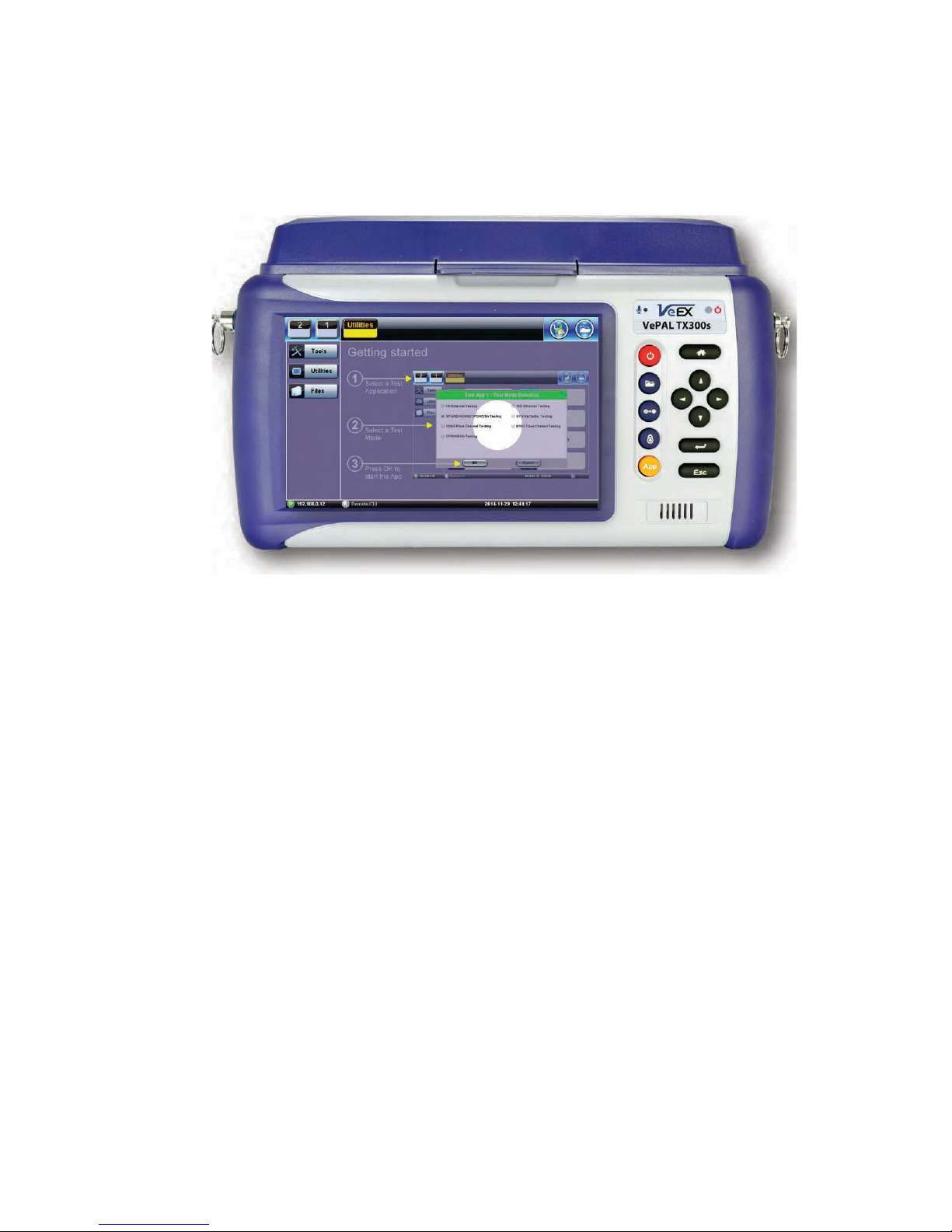
5.2 Front Panel Layout
The picture below depicts the TX300s. Layout will vary depending on FX150, FX300, MTTplus,
or RXT platforms.
5.2.1 LED Indicators
Power/Charge LED - indicates battery charging is in progress. LED turns off when battery is
fully charged.
Note: The device is powered from the built-in Li-Ion battery and can be operated with the AC/
DC adaptor plugged in.
5.2.2 Rubber Keypad
• Home Key: Resets user interface to Main menu
• Navigation/Marker Keys: Used to move markers or navigate menus (in the event
touch screen is disabled for any reason) Enter Key: Enters the desired value or selects
active menu, check box or radio button
• Escape Key: Exits the menu
• App Key: Toggles between active test applications (OTDR, OLS, OPM, VFL)
• Lock/Save Screen Key: Locks the touch panel or saves the screen (bmp) depending
on setting defined in Utility menu
• LED History Key: Resets LED condition (depends on test application)
• Save Trace/Result Key: Saves test result file (OTDR, OPM, Ethernet, Fiberscope -
depends on active application and unit configuration)
OTDR Series e-Manual, D07-00-076P-RevC00 Page 15 of 107
5.2.3 Menu Navigation
Navigate between test applications, setup menus, tabs, or active functions using the supplied
stylus or by using up/down arrows followed by “Enter.”
“Getting started” information is displayed after power up.
Select a Test Application
• FX150: Application #1 is loaded by default. Select OTDR, VFL, OPM, OLS by clicking
the icon on the main menu. The Fiberscope icon can be found on the Advanced Tools
screen.
• TX300s: Select Application 2, which corresponds to the optical test function blade #2,
located on the top connector panel. Select OTDR, VFL, OPM, or OLS by clicking the
icon on the main menu
• FX300/MTTplus/RXT: Select Application 1, which corresponds to the module, inserted
into the module slot. Select Fiber testing from the Test mode selection and press OK.
The OTDR, VFL, OPM, and OLS test functions will be displayed on the main menu.
Note:
Touch Screen Navigation - The unit is equipped with a state of art, full color, LCD TFT touch
screen. When used properly, the screen is designed to give years of reliable and precise
operation. Always use the stylus supplied with the unit to operate the touch screen. Never use
any sharp object such as a ballpoint pen, screwdriver, or similar item as this will damage the
screen and void the warranty.
OTDR Series e-Manual, D07-00-076P-RevC00 Page 16 of 107
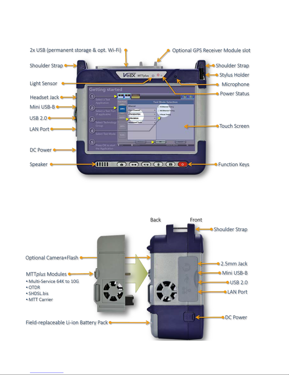
5.3 MTTplus Overview
5.3.1 MTTplus Side View
OTDR Series e-Manual, D07-00-076P-RevC00 Page 17 of 107
option).
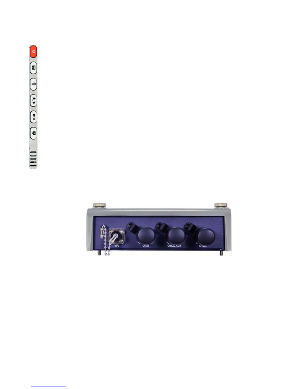
5.3.2 MTTplus Control Panel
• Power: Press for 2 seconds to turn the test set ON or OFF (prevents
accidental ON/OFF) If a test is running when the power off is started, test
is terminated and results may not be automatically saved.
• Save Test Results: Saves the current Test Results with customized or
auto naming.
• Lock/Unlock Touch Screen or Screen Capture: Can also be
programmed to Capture Screen images. Go to >Utilities >Settings
>Global >Save Settings to set save and image compression options.
• Volume and Brightness Control: (it also acts as the MTT F1 key, when
the is active) Brings up the Sound and screen Brightness controls; Use
cursor buttons to adjust the levels.
• Clear History: Resets blinking LED reminders of past Errors or Alarms
Test results are not affected. (not used with OTDR)
• Camera App: Launches the optional Camera App to help document the
job site, damage, connections, etc. Requires the camera (factory-installed
5.3.3 MTTplus OTDR Module Top View
OTDR Series e-Manual, D07-00-076P-RevC00 Page 18 of 107
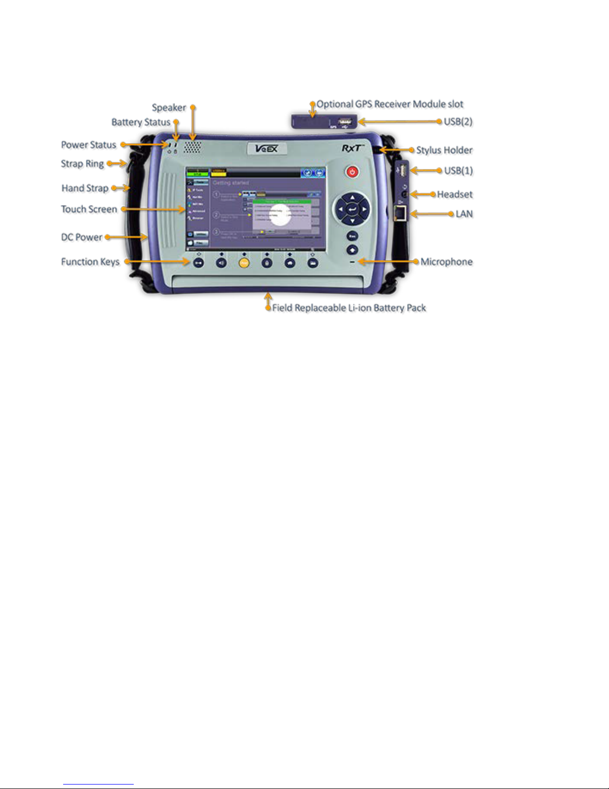
5.4 RxT Overview

OTDR Series e-Manual, D07-00-076P-RevC00 Page 19 of 107
affected. (not used in OTDR)
5.4.1 RxT Front Panel
• Power: Press for 2 seconds to turn
the test set ON or OFF (prevents
accidental ON/OFF)
• Cursor Keys: Application
dependent; May offer alternative
GUI Navigation to touch screen
(e.g. while wearing gloves in cold
weather)
• Enter: Application dependent
• Escape: Application dependent
• Alt Alternate function: Links the
buttons to the GUI soft Function
Keys (MTT Emulation Mode only)
• Clear History: Resets blinking
LED reminders of past Errors or
Alarms. Test results are not
• Volume and Brightness Control:
(it also acts as the MTT F1 key,
when the Alt key is active) Brings
up the Sound and screen
Brightness controls; Use cursor
buttons to adjust the levels
• Test Application Selector (it also
acts as the MTT F2 key, when the
Alt key is active): Quickly switches
back and forth between the active
Test Application and RXT platform.
Utilities functions; Active test is not
affected.
• Lock/Unlock Touch Screen: Can
also be programmed to capture
Screen Shots (>Utilities
>Settings>Global>Save Settings)
• Home: Quickly bring users back to
the Main Menu
• Save Test Results: Saves the
current Test Results with
customized or auto naming format
OTDR Series e-Manual, D07-00-076P-RevC00 Page 20 of 107
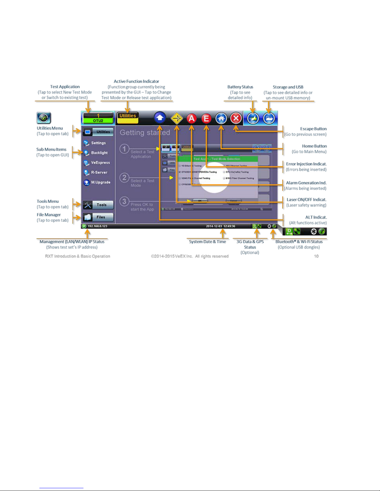
5.4.2 Getting Started
A Quick Guide is always present in the Home screen after boot up.
This screen can be displayed at any time from any screen.
The test port group is assigned to the Fiber application when the 410 module is installed. All
options associated with the 410 OTDR module will be installed.
OTDR Series e-Manual, D07-00-076P-RevC00 Page 21 of 107
Main menu
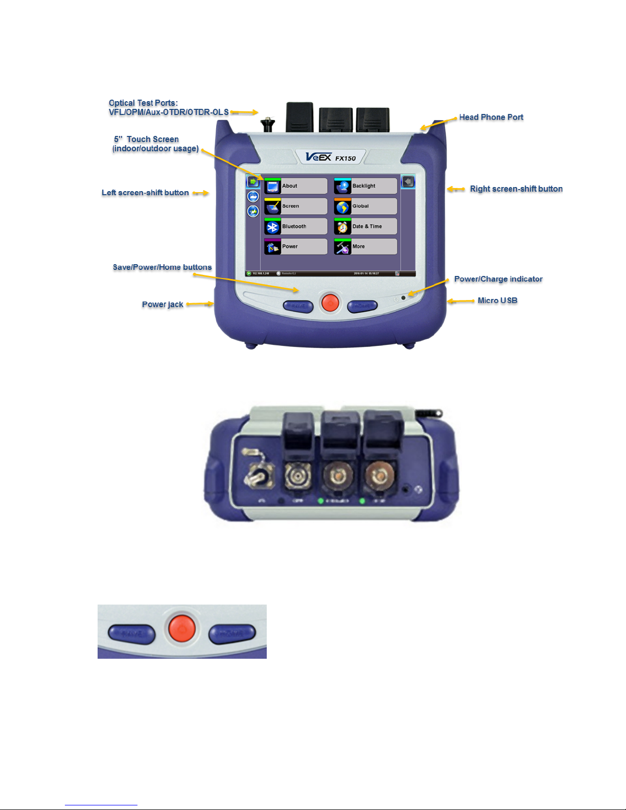
5.5 FX150 Overview
5.5.1 FX150 Test Ports
5.5.2 FX150 Keypad
FFXX115500PPllaattffoorrmm
VVFFLL//OOPPMM//AAuuxx--OOTTDDRR//OOTTDDRR--OOLLSS
• Save: Saves the screen (bmp)
• Power: Press for 2 seconds to turn
the test set ON or OFF (prevents
accidental ON/OFF)
• Home: Resets user interface to
OTDR Series e-Manual, D07-00-076P-RevC00 Page 22 of 107
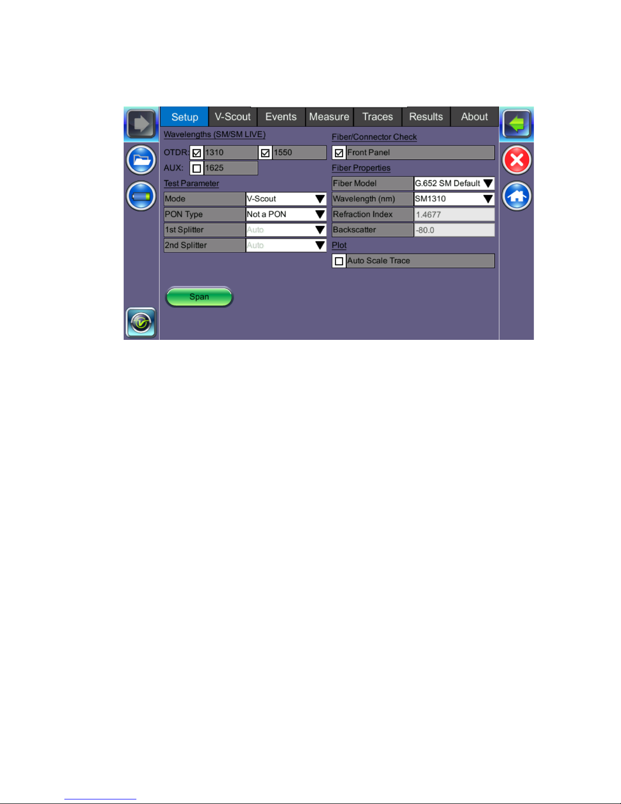
5.5.3 FX150 Screen Navigation
OOTTDDRRSSccrreeeenn
Use the top tabs of the FX150 screen to access test measurement controls and view results.
On the bottom bar, you can see:
• IP address, when connected
• Remote control connection status
• Date and time
• Bluetooth and WiFi connection indicators

OTDR Series e-Manual, D07-00-076P-RevC00 Page 23 of 107
access the Utilities screen.
screen.
5.5.3.1 View/Hide side menu panels
The left and right panels of the display provide icons to access key functions of the FX150.
These panels can be turned on or off to enable a better view of the application screens.
Use the shift keys located on the left and right sides of the unit to toggle on/off the left
and right menu panels.
Press the LEFT SHIFT KEY to access:
File Storage – Tap to see the size and current capacity
of the internal SSD storage.
Power Source Indicator– Indicates when unit is
powered by external AC power and battery charging
level. Tap to see battery charge status.
V key / Fiber – Tap to access all Fiber Test Modes or
Press the RIGHT SHIFT KEY to access test control buttons and the following:
Home – Tap to return to the OTDR Main Menu.
Escape/Exit – Tap to return to the previous screen.
Arrow – Tap to enter the unit System Settings and Tools
Start – Begin trace.
Green arrow – Switch λ active trace
Real Time OTDR – See trace in real time.
OTDR Series e-Manual, D07-00-076P-RevC00 Page 24 of 107
5.5.4 Setting up FX150 WiFi
The FX150 unit contains an optional built-in WiFi interface allowing you to easily transfer
OTDR traces and upgrade software on the unit.
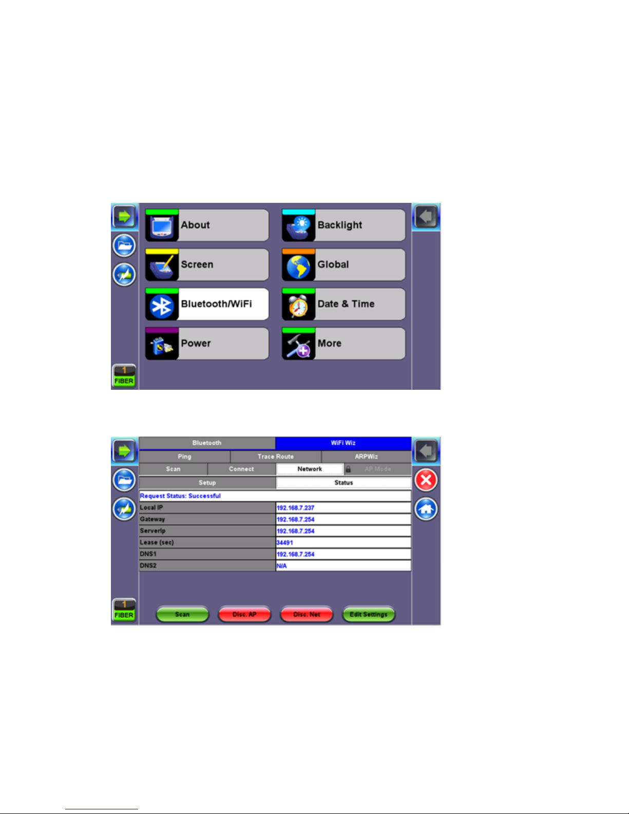
5.5.4.1 Access WiFi option
1. Press Utilities or the HOME key, and then press Bluetooth/WiFi.
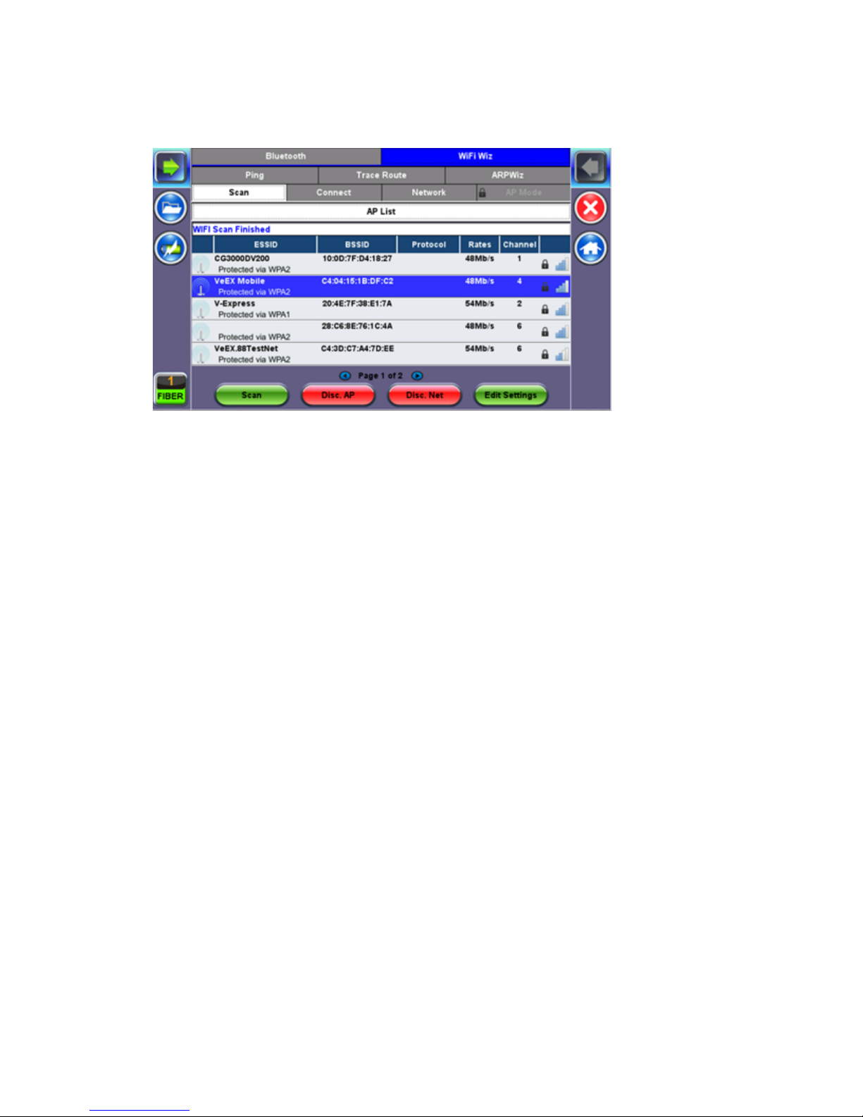
2. Select the WiFi Wiz tab.
OTDR Series e-Manual, D07-00-076P-RevC00 Page 25 of 107
5.5.4.2 Connect to a WiFi network
1. Press Scan to see all networks
2. Select one of the available networks and the Edit Settings key will appear to the right.
Once selected, an Edit Settings function key appears to the right.
3. Tap on Edit Settings to change the Encryption Type and enter the WiFi Key or Connect
AP. The label will change to Disc. AP upon successful connection and the Connect Net
key will appear.
Encryption Type: Supported encryption types include WEP, WPA, and WPA2.
Password: Security phrase or password necessary to access SSID and network. Tap the
Password field to enter the network password on the pop-up keypad (ASCII formatting
supported).
4. Press Apply after selecting the Encryption Type and entering the Key.
5. If the encryption menu was accessed via Connect AP, the test set will connect to the AP
automatically after hitting Apply.
6. If the encryption menu was accessed via Edit Settings, press Connect AP to connect to
the AP.
7. After a successful connection to the Access Point, press Connect Net to obtain an IP
address and access the additional IP tests like Ping, Trace Route etc.
Note: Passwords are case sensitive. If the user enters the wrong network key, the test set will
still connect to the Access Point, but will not be able to connect to the web or perform the Ping
test.
OTDR Series e-Manual, D07-00-076P-RevC00 Page 26 of 107
5.6 Customizing Your Tester
You can customize the settings on your OTDR device in the Utilities>Settings menu:
• About: Displays serial #, MAC address, software version, software options installed and
related product information
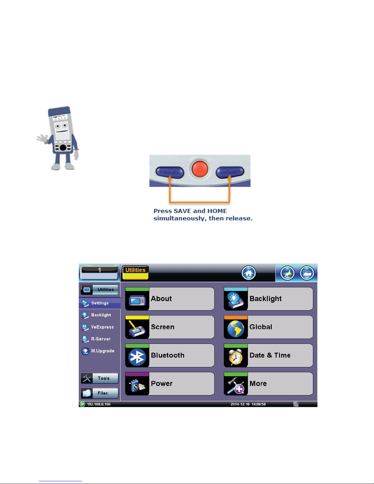
• Screen: Displays calibration menu.
Activating Touchscreen Calibration Mode
You can activate the Touchscreen Calibration Mode using the
keypad by pressing SAVE + HOME keys simultaneously, then
releasing. Press SAVE + HOME again to start a new calibration.
• Backlight: User defined settings when unit is used on Battery or AC power including
Brightness settings

OTDR Series e-Manual, D07-00-076P-RevC00 Page 27 of 107
• Global: Various settings including:
• General
• Language: English, German, French, Chinese, Japanese, Korean and others (de-
pends on software version). You must reboot the device to fully activate the new
language
• Unit: Metric or US
• Audible alarm: sounds alarm when battery runs low or other alarm condition is met
• Show Password: Shows/Hides password in IP setups and other menus where
password is displayed.
• User Interface: International or USA
• WiFi Auto Connect: On or Off
• Auto Color Scheme: On or Off
• RTU-410 (OTDR) Emulation Mode: On or Off
• OTG Port Mode: Host or Device
• Telnet: On or Off
• Share Result: On or Off
• Storage Settings
• File name prefix (for setting prefix for OTDR sor files or other test results):
• Profile deleting: Auto or Prompt user before Deleting
• Profile saving: Auto or Prompt user before Overwrite
• Result saving: Manual or prompt user before saving
• Advance saving: Enables/Disables advanced saving properties
• Save Settings
• Lock/Save Screen: Lock Screen or Save Screen (compression level and maximum
number of screenshots that can be saved.
OTDR Series e-Manual, D07-00-076P-RevC00 Page 28 of 107
6.0 Test Fiber and Initial Preparation Introduction
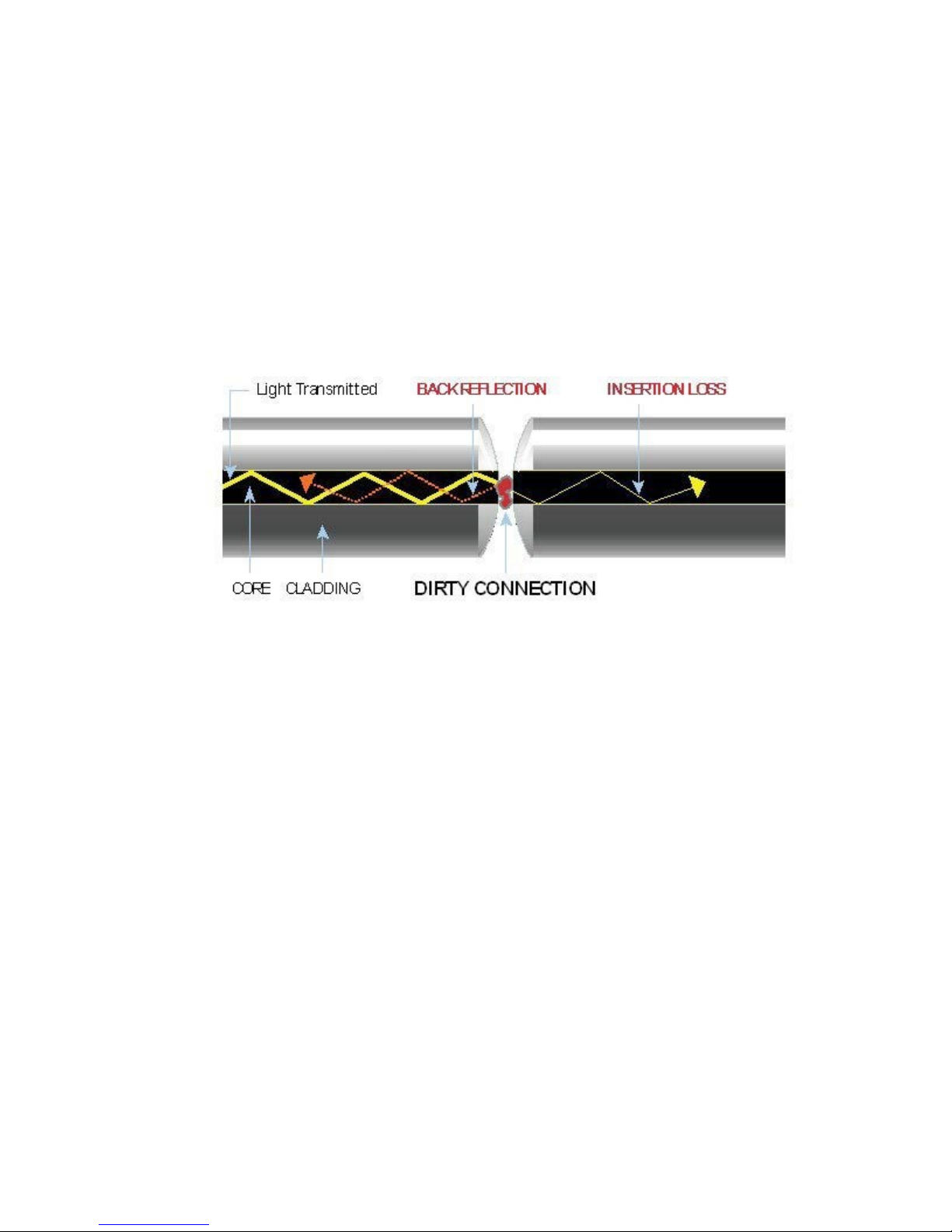
Dirt, dust, and other contaminants severely impact high-speed data transmission in optical
fibers and dirty connector end-faces are often the #1 cause of link failures. High insertion loss
and/or high back reflection can result in transmission loss or high bit errors and poor BER.
Furthermore, most measurement variations and test repeatability conditions in fiber-optic
systems can be traced back to the cleanliness of optical connections. Contamination of fiber
end faces not only affects optical power levels but also impacts back reflectance performance
and levels which is harmful to sensitive optical components.
OTDR Series e-Manual, D07-00-076P-RevC00 Page 29 of 107
6.1 Contamination
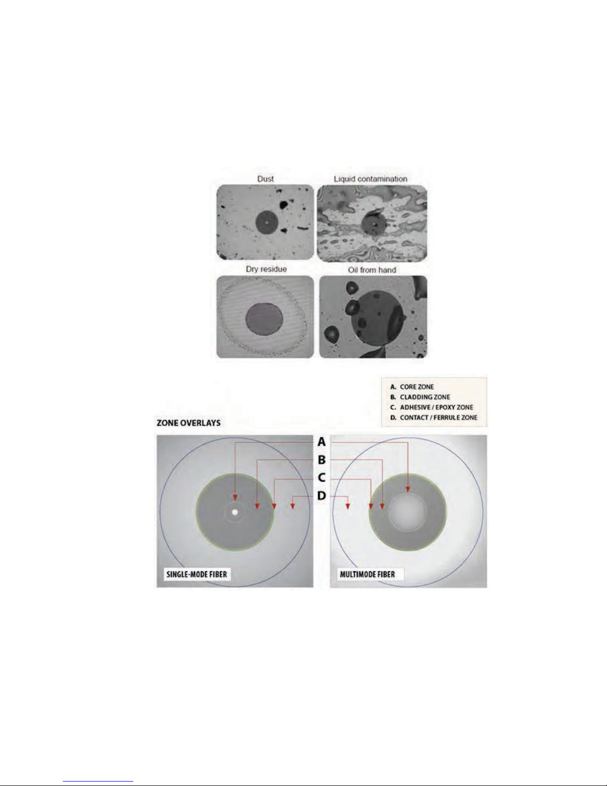
Optical connectors are susceptible to contamination from air borne particles and human body
oils when exposed. Left over liquid residue from improper cleaning can also leave the fiber end
face contaminated. The smaller the fiber core, the more severe the problem is likely to be,
especially when you consider that fiber core diameters can range from 62.5 microns all the
way down to 8 microns in size. Below are some examples viewed by a 400x Fiber microscope:
6.2 Inspection
Whenever possible, inspect the fiber-optic connection (connectors, bulkheads, and test
interfaces) with a fiber microscope. It is recommended to wear laser safety glasses when you
work with fiber-optic connections, and always check that you disconnect the laser or
transmitter before you begin cleaning the connector end faces.

OTDR Series e-Manual, D07-00-076P-RevC00 Page 30 of 107
6.3 Cleaning Procedure
To ensure proper and effective cleaning of optical fiber connectors and interfaces, please
equip yourself with the following cleaning materials:
• Isopropyl alcohol
• Lint free soft tissues
• Ferrule cleaners (1.25mm and 2.5mm versions)
• Connector reel cleaners (CleTop or similar)
Procedure
1. Dab the contaminated connector end-face with a wipe that has been dampened with
Isopropyl alcohol - the solvent will dissolve and remove contaminants that have dried and
attached to the connector or fiber end-face.
2. Rub the fiber end-face perpendicularly against a dry lint free wipe several times.
3. Alternatively, use compressed air to dry the surface quickly. Do not blow or allow the
connector end face to air dry as this may leave a residue behind which is often more
difficult to clean and which can attract even more dirt.
4. Re-inspect the fiber end-face with an optical microscope to check that all the contaminants
have been removed properly - if not, please repeat the process.
Note:
Using Compressed Air - In some clean air situations, you can use filtered air, which is free of
oil and moisture to remove debris and clean a fiber optic connection. However, unless you
follow very strict cleaning procedures, air-driven contaminants can cause more problems.
If you need to use compressed air, hold the can upright. If the can is held at a slant, propellant
could escape and dirty your optical device. First spray into the air, as the initial stream of
compressed air could contain some condensation or propellant. Such condensation leaves
behind a filmy deposit.
 Loading...