


OTDR Series e-Manual, D07-00-076P-RevC00 Page 1 of 107
OTDR Series e-Manual, D07-00-076P-RevC00 Page 1 of 107
• FX150
• FX300
• MTTplus-410
• RXT-4100
• TX300s
OTDR Series

OTDR Series e-Manual, D07-00-076P-RevC00 Page 2 of 107
Table of Contents
1.0 ABOUT THIS USER MANUAL ..................................................................................... 5
2.0 PRODUCT INTRODUCTION ........................................................................................ 6
2.1 PLATFORM HIGHLIGHTS (FX150/FX300/MTTPLUS/RXT/TX300S) .............................................. 6
2.2 KEY FEATURES .......................................................................................................................... 7
2.3 PACKAGE CONTENTS ................................................................................................................. 8
3.0 SAFETY INFORMATION .............................................................................................. 9
4.0 THEORY OF OPERATION ......................................................................................... 10
4.1 OTDR ...................................................................................................................................... 10
4.2 LIGHT SOURCE ......................................................................................................................... 11
4.3 OPTICAL POWER METER .......................................................................................................... 11
4.4 VISUAL FAULT LOCATOR .......................................................................................................... 11
5.0 BASIC OPERATION ................................................................................................... 12
5.1 TEST PORTS AND INTERFACES ................................................................................................. 12
5.2 FRONT PANEL LAYOUT ............................................................................................................. 14
5.2.1 LED Indicators ...................................................................................................................................... 14
5.2.2 Rubber Keypad ..................................................................................................................................... 14
5.2.3 Menu Navigation .................................................................................................................................. 15
5.3 MTTPLUS OVERVIEW ............................................................................................................... 16
5.3.1 MTTplus Side View ............................................................................................................................... 16
5.3.2 MTTplus Control Panel ........................................................................................................................ 17
5.3.3 MTTplus OTDR Module Top View ....................................................................................................... 17
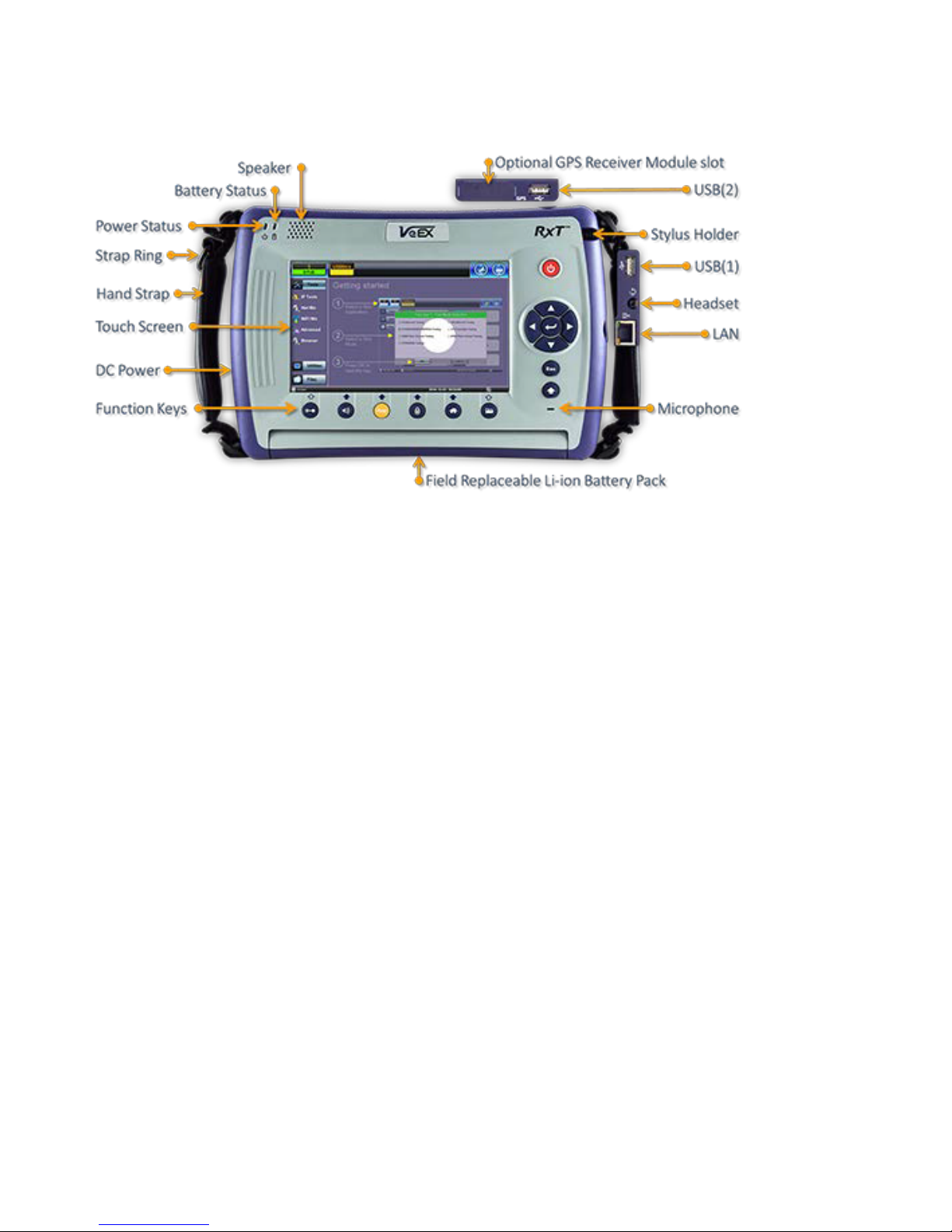
5.4 RXT OVERVIEW ........................................................................................................................ 18
5.4.1 RxT Front Panel .................................................................................................................................... 19
5.4.2 Getting Started ..................................................................................................................................... 20
5.5 FX150 OVERVIEW .................................................................................................................... 21
5.5.1 FX150 Test Ports .................................................................................................................................. 21
5.5.2 FX150 Keypad ....................................................................................................................................... 21
5.5.3 FX150 Screen Navigation .................................................................................................................... 22
5.5.3.1 View/Hide side menu panels ......................................................................................................... 23
5.5.4 Setting up FX150 WiFi ......................................................................................................................... 24
5.5.4.1 Access WiFi option ........................................................................................................................ 24
5.5.4.2 Connect to a WiFi network ............................................................................................................ 25
5.6 CUSTOMIZING YOUR TESTER .................................................................................................... 26
6.0 TEST FIBER AND INITIAL PREPARATION INTRODUCTION ................................. 28
6.1 CONTAMINATION ...................................................................................................................... 29
6.2 INSPECTION .............................................................................................................................. 29
6.3 CLEANING PROCEDURE ............................................................................................................ 30
6.4 BEST PRACTICES ..................................................................................................................... 31
6.5 CONNECTORS .......................................................................................................................... 32
6.5.1 Connector Types .................................................................................................................................. 32
6.5.2 Connector Performance and Polishing .............................................................................................. 34
6.6 FIBER CABLES AND FIBER PATCHCORDS .................................................................................. 36
6.6.1 Fiber Cable ............................................................................................................................................ 36
6.6.2 Fiber Patchcord .................................................................................................................................... 37
6.7 INSERTING THE FIBER ............................................................................................................... 39
6.7.1 Preventing Inaccurate Readings ........................................................................................................ 39
6.8 FIBER SCOPE UTILITY (FX150, FX300, MTTPLUS, RXT) ........................................................... 39

OTDR Series e-Manual, D07-00-076P-RevC00 Page 3 of 107
6.8.1
Fiber Scope Overview .......................................................................................................................... 39
6.8.2 Connecting the Fiber Scope ............................................................................................................... 40
6.8.3 Setup ..................................................................................................................................................... 41
6.8.4 Analysis ................................................................................................................................................ 41
6.8.5 Capture Screen ..................................................................................................................................... 42
6.8.6 Captured Files ...................................................................................................................................... 43
6.8.7 Connector Face Analysis .................................................................................................................... 44
6.8.8 Connector Face Analysis Results Table ............................................................................................ 45
6.8.8.1 HTML Report ................................................................................................................................. 46
6.8.8.2 PDF Report .................................................................................................................................... 47
6.8.9 Managing Fiberscope Results with File Manager ............................................................................. 48
6.8.9.1 File Manager Filters ....................................................................................................................... 49
6.8.10 Fiber Scope Image Management Software (ViS400D only) ......................................................... 50
6.8.11 Fiber Scope Image Management Software (VS-500 and DI-1000 only) ....................................... 51
6.9 VISUAL FAULT LOCATOR (VFL) ................................................................................................ 54
6.9.1 Using the VFL ....................................................................................................................................... 55
6.10 OPTICAL LIGHT SOURCE (OLS) ................................................................................................ 56
6.10.1 Accessing and setting up the Optical Light Source ..................................................................... 57
6.10.2 Using the Optical Light Source ...................................................................................................... 58
6.11 OPTICAL POWER METER (OPM) ............................................................................................... 59
6.11.1 Setting up the Optical Power Meter ............................................................................................... 59
6.11.1.1 USB OPM Setup Options .............................................................................................................. 60
6.11.1.2 Setting Pass/Fail Limits ................................................................................................................. 61
6.11.2 Using the built-in OPM .................................................................................................................... 62
6.12 OPTICAL LOSS TEST SET (OLTS) (NOT CURRENTLY SUPPORTED) ............................................. 64
6.13 RESULTS .................................................................................................................................. 64
7.0 WORKING WITH THE OTDR ..................................................................................... 66
7.1 TEST SETUP ............................................................................................................................. 66
7.1.1 Initial Settings ....................................................................................................................................... 66
7.1.2 Manual mode ........................................................................................................................................ 67
7.1.3 Auto mode ............................................................................................................................................ 70
7.1.4 V-Scout mode (optional) ...................................................................................................................... 71
7.1.4.1 Setting up and Using V-Scout mode ............................................................................................. 73
7.1.4.2 V-Scout symbols ............................................................................................................................ 74
7.2 THRESHOLDS ........................................................................................................................... 76
7.2.1 Analysis Thresholds ............................................................................................................................ 76
7.2.2 Pass/Fail Thresholds ........................................................................................................................... 77
7.2.3 Event Table ........................................................................................................................................... 78
7.2.4 Autosave Parameters .......................................................................................................................... 78
7.2.5 Cloud Credentials ................................................................................................................................ 80
7.3 MAKING MEASUREMENTS ......................................................................................................... 81
7.3.1 Trace Display ........................................................................................................................................ 81
7.4 EVENTS .................................................................................................................................... 82
7.4.1 Event Table ........................................................................................................................................... 82
7.4.2 Event Types .......................................................................................................................................... 83
7.4.3 Event Editing ........................................................................................................................................ 83
7.5 MEASURE MODE ...................................................................................................................... 84
7.5.1 Markers Controls .................................................................................................................................. 84
7.5.1.1 Marker Operation ........................................................................................................................... 84
7.5.1.2 Zoom/Scroll Controls ..................................................................................................................... 85
7.5.2 Distance Measurements ...................................................................................................................... 86
7.5.3 Loss Measurements ............................................................................................................................. 86
7.5.3.1 Two Point Loss (2-Pt Loss) ........................................................................................................... 86
7.5.3.2 Two Point LSA (2-Pt LSA) ............................................................................................................. 87
7.5.4 Splice Loss Measurement ................................................................................................................... 87
7.5.5 Reflectance Measurement ................................................................................................................... 88

OTDR Series e-Manual, D07-00-076P-RevC00 Page 4 of 107
7.5.6
ORL Measurement ............................................................................................................................... 89
7.6 TRACES ................................................................................................................................... 90
7.6.1 Trace Properties ................................................................................................................................... 91
7.6.2 Saving OTDR Traces ............................................................................................................................ 93
7.6.3 Saving OTDR Traces with Embedded GPS and Camera Image ...................................................... 94
7.6.3.1 Obtaining GPS Coordinates .......................................................................................................... 94
7.6.4 Adding GPS to OTDR file (optional feature) ...................................................................................... 94
7.6.5 Adding Camera Image OTDR file (MTTplus only) ............................................................................. 95
7.7 RESULTS .................................................................................................................................. 97
7.7.1 File Management .................................................................................................................................. 98
7.7.2 Saving/Printing Traces to PDF/USB/Bluetooth ................................................................................. 99
7.7.3 File Operations ................................................................................................................................... 100
7.8 ABOUT TAB ............................................................................................................................ 101
8.0 REVEAL SOFTWARE .............................................................................................. 102
9.0 WARRANTY AND SOFTWARE ............................................................................... 103
10.0 PRODUCT SPECIFICATIONS ................................................................................. 105
11.0 CERTIFICATIONS AND DECLARATIONS .............................................................. 106
12.0 ABOUT VEEX ........................................................................................................... 107

OTDR Series e-Manual, D07-00-076P-RevC00 Page 5 of 107
1.0 About This User Manual
This user manual is suitable for novice, intermediate, and experienced users and is intended to
help you successfully use the features and capabilities of the FX150, FX300, MTTplus, RXT,
and TX300s OTDR series. It is assumed that the user has basic computer experience and
skills, and is familiar with Optical Fiber, telecommunication concepts, terminology, and safety.
Every effort was made to ensure that the information contained in this user manual is accurate.
Information is subject to change without notice and we accept no responsibility for any errors
or omissions. In case of discrepancy, the web version takes precedence over any printed
literature. The content in this manual may vary from the software version installed in the unit.
© Copyright 2006-2017 VeEX, Inc. All rights reserved.
VeEX, VePAL, Sunrise Telecom, Agizer, Optixsoft, Sunlite, Sunset, RXT, MTT, FX, TX, OPX,
and Fiberizer are trademarks of VeEX, Inc. and/or its affiliates in the USA and certain other
countries. All trademarks or registered trademarks are the property of their respective
companies. No part of this document may be reproduced or transmitted electronically or
otherwise without written permission from VeEX, Inc.
This device uses software either developed by VeEX, Inc. or licensed by VeEX, Inc. from third
parties. The software is confidential and proprietary of VeEX, Inc. The software is protected by
copyright and contains trade secrets of VeEX, Inc. or VeEX's licensors. The purchaser of this
device agrees that it has received a license solely to use the software as embedded in the
device, and the purchaser is prohibited from copying, reverse engineering, decompiling, or
disassembling the software.
For more technical resources, visit the VeEX, Inc. web site at www.veexinc.com.
If you need assistance or have questions related to the use of this product, call or e-mail our
customer care department for customer support. Before contacting our customer care
department, you must have your product serial number and software version ready. Please
provide this number when contacting VeEX customer service.
Customer Care:
Phone: + 1 510 651 0500
E-mail: customercare@veexinc.com
Website: www.veexinc.com

OTDR Series e-Manual, D07-00-076P-RevC00 Page 6 of 107
2.0 Product Introduction
The FX150, FX300, MTTplus, RXT, and TX300s feature an OTDR optimized for the installation
and troubleshooting of FTTx, PON, CATV, Mobile Backhaul, and Metro fiber networks.
2.1 Platform Highlights (FX150/FX300/MTTplus/RXT/TX300s)
• Robust, compact hand-held design for demanding field test environments
• High resolution, TFT color touch-screen viewable in any lighting condition. See the
platform’s datasheet for screen size.
• Fast boot-up time essential for fiber restoration
• Internal data storage varies with model. See the platform’s datasheet for more
information at www.veexinc.com.
• USB-A Host Interface supporting (FX300/MTTplus/RXT/TX300s):
• USB flash drives (not available on FX150)
• Fiber inspection probe connection (FX150 requires OTG cable)
• Bluetooth option available
• 3G UMTS data card support (not available on all models). See the platform’s
datasheet for more information at www.veexinc.com.
• Micro USB interface OTG to support (FX150):
• USB flash drives
• Fiber inspection probes
• Ethernet (10/100T) LAN Interface supporting(FX300/MTTplus/RXT/TX300s):
• Remote control
• Transfer OTDR test data
• Perform software upgrades
• Basic IP testing (Ping, Trace route, Web browser)
• Built-in Wireless and Bluetooth options supporting (FX150 standard;
FX300/MTTplus/RXT optional. See the platform’s datasheet for availability at
www.veexinc.com.):
• Software upgrades and uploading test data via wireless connection
• Pairing applications with Mobile Smartphones and Tablet PCs
• Rechargeable Li-Ion battery with capacity indicator, low voltage alarm and Auto-off
function:
• FX150 platform – 10,000 mAH battery
• FX300/TX300s platform – 5200 mAH battery
• MTTplus platform – 5400 mAH battery
• RXT platform - 8400 mAH battery

OTDR Series e-Manual, D07-00-076P-RevC00 Page 7 of 107
• Continuous operation of > 8 hours per Bellcore TRNWT-001138 (platform dependent)
• ReVeal software to transfer fiber test data, upgrade software and perform remote
control (check with factory on availability)
• Fiberizer Cloud to upload fiber test data
• VeExpress to check/upgrade software and installed options status (not available on
FX300 or FX150)
2.2 Key Features
• FTTx optimized parameters for best dead zones
• Filtered 1625 or 1650 nm OTDR port for in-service measurements
• Live fiber detection with embedded power meter
• Dynamic range up to 50 dB (model dependent)
• Event dead zone < 1m, attenuation dead zone < 4m
• Singlemode wavelength options - 1310, 1490, 1550, 1625 and 1650 nm (CWDM and
DWDM C-band also available)
• Multimode wavelength options - 850 and 1300 nm
• Telcordia SR-4731.sor file formats
• Generate and save traces in sor, pdf or csv format (model dependent)
• Auto mode with automated trace diagnostics, simplified setup and events detection
• Optional V-Scout mode – Intelligent Link Mapping using intuitive icons derived from
multiple test acquisitions
• Markers for distance, attenuation, reflectance and splice loss measurements
• Optional universal interface with interchangeable optical adaptors (SC, ST, FC, LC) for
OTDR port
• Power meter, light source, fiber inspection probe and VFL options
• Remote measurement via USB or WiFi connection using Fiberizer Desktop software

OTDR Series e-Manual, D07-00-076P-RevC00 Page 8 of 107
2.3 Package Contents
• OTDR (FX300, FX150, TX300S OTDR blade, RXT-4100 module or MTTplus-410
module)
• AC/DC adaptor
• Input: 100-240 VAC (50/60 Hz), 1.5A max - (MTTPLUS: 5.3A max; FX150: 1.5A
max)
• Output: 16VDC - (MTTPLUS: 15VDC; FX150: 12VDC)
• Ethernet cable (FX300, TX300S OTDR blade, RXT module or MTTplus module)
• Li-Ion battery (capacity depends on platform)
• USB memory stick or CD-ROM containing:
• OTDR Users’ Manual (pdf)
• Reveal and Fiberizer Desktop software
• Software Upgrade Instructions
• Nylon Soft Carry case
OTDR Series e-Manual, D07-00-076P-RevC00 Page 9 of 107
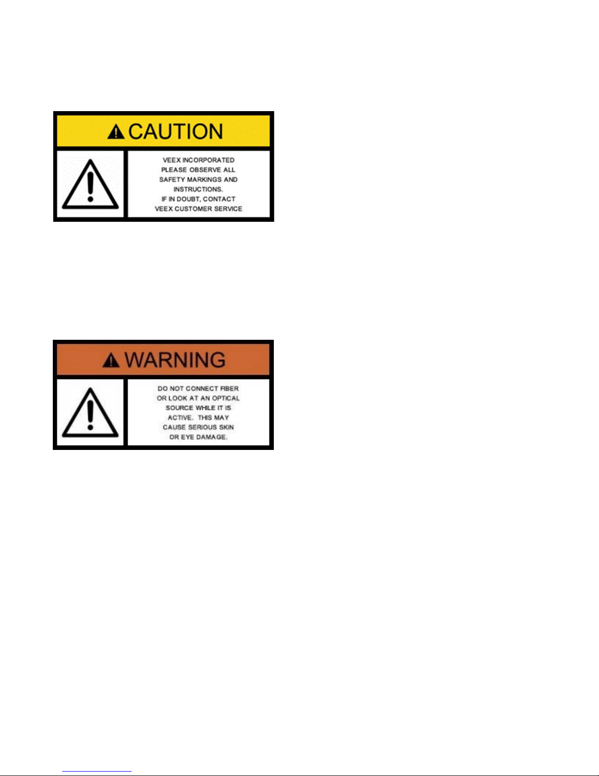
3.0 Safety Information
Safety precautions should be observed during all phases of operation of this instrument. The
instrument has been designed to ensure safe operation however please observe all safety
markings and instructions. Do not operate the instrument in the presence of flammable gases
or fumes or any other combustible environment. VeEX Inc. assumes no liability for the
customer's failure to comply with safety precautions and requirements.
Optical Connectors
The test platform displays a laser warning icon when the laser source is active to alert the user
about a potentially dangerous situation. Make sure that optical sources are inactive before
connecting fiber to the test set to avoid skin or eye damage, or damage to the unit. It is
recommended to:
• Deactivate the laser before connecting or disconnecting optical cables or patchcords.
• Never look directly into an optical patchcord or an optical interface (e.g. CFP, CFP2,
CFP4, QSFP+, SFP+, SFP, OTDR, LS, VFL) while the laser is enabled. Even though
optical transceivers are typically fitted with Class 1 lasers, which are considered eye
safe, optical radiation for an extended period can cause irreparable damage to the eyes.
• Never use a fiber microscope to check the optical connectors when the laser source is
active.
Electrical Connectors
Telephone lines may carry dangerous voltages. Always connect the electrical test ports to
known test interfaces which carry low level signals.
OTDR Series e-Manual, D07-00-076P-RevC00 Page 10 of 107
4.0 Theory of Operation
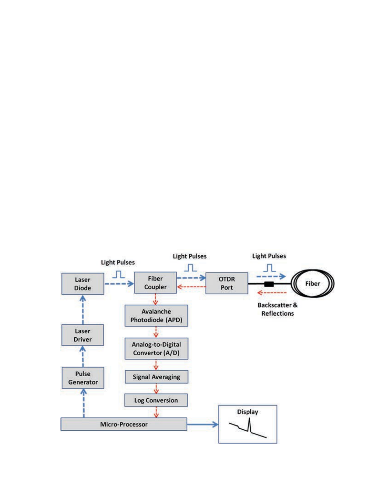
4.1 OTDR
The principle of OTDR operation is based on measuring the Rayleigh back scattering signal
when a single powerful optical pulse passes through an optical fiber. The weak back scattering
signal is registered by an optical receiver, converted into digital form and averaged many
times.
The OTDR calculate distance with next formula:
Distance = c * t / (2 * n)
where c – light speed in vacuum, n – optical fiber index of refraction, t – time
delay between pulse emit and it
registration by receiver
Each sample converted by ADC into digital form is registered in the RAM. To measure the
back-scattering signal precisely, repeated triggering optical pulses is performed. The processor
averages samples, corresponding to the same points of the optical fiber that leads to the
increasing signal-noise ratio. After several cycles, the obtained signal values are transferred
from RAM and displayed. Then, the process of measuring, averaging, and cleaning RAM
registers is repeated again.
OTDR – Principle of Operation

OTDR Series e-Manual, D07-00-076P-RevC00 Page 11 of 107
4.2 Light Source
An optional light source is available and designed for generating continuous optical radiation.
The light source output is the same as the OTDR port and uses the same laser diodes and
optical splitter. The radiation power is stabilized with the help of external photodiode and power
stabilization circuit.
The light source has two operation modes: Continuous and Modulated/tone (270, 1000 and
2000Hz).
The average power at modulation mode is 2 times lower (3dB) than in continuous mode of
operation.
4.3 Optical Power Meter
The OPM is equipped with an InGaAs photodiode (1mm diameter) to measure optical power.
For standard power PM1 measurement range (+10dBm), radiation falls directly on the
photodiode. The OPM will support both MM and SM fiber with the APC or UPC connector type.
For extended measurement PM2 range (+25dBm), an integrating sphere with a photodiode is
used. Input power is attenuated by the integrating sphere by approximately 100 times.
The current of the photodiode is amplified and converted into digital form with the help of
analog-digital converter. The received digital signal is processed by microprocessor and the
value of the measured optical power is displayed.
4.4 Visual Fault Locator
The unit is equipped with an optional Visual Light Locator (VFL) to visually identify breaks in
the fiber typically hidden in the OTDR dead zone.
• Output power: 0 dBm (Typical)
• Operation modes: Continuous wave (CW) or 2Hz modulation
OTDR Series e-Manual, D07-00-076P-RevC00 Page 12 of 107
5.0 Basic Operation
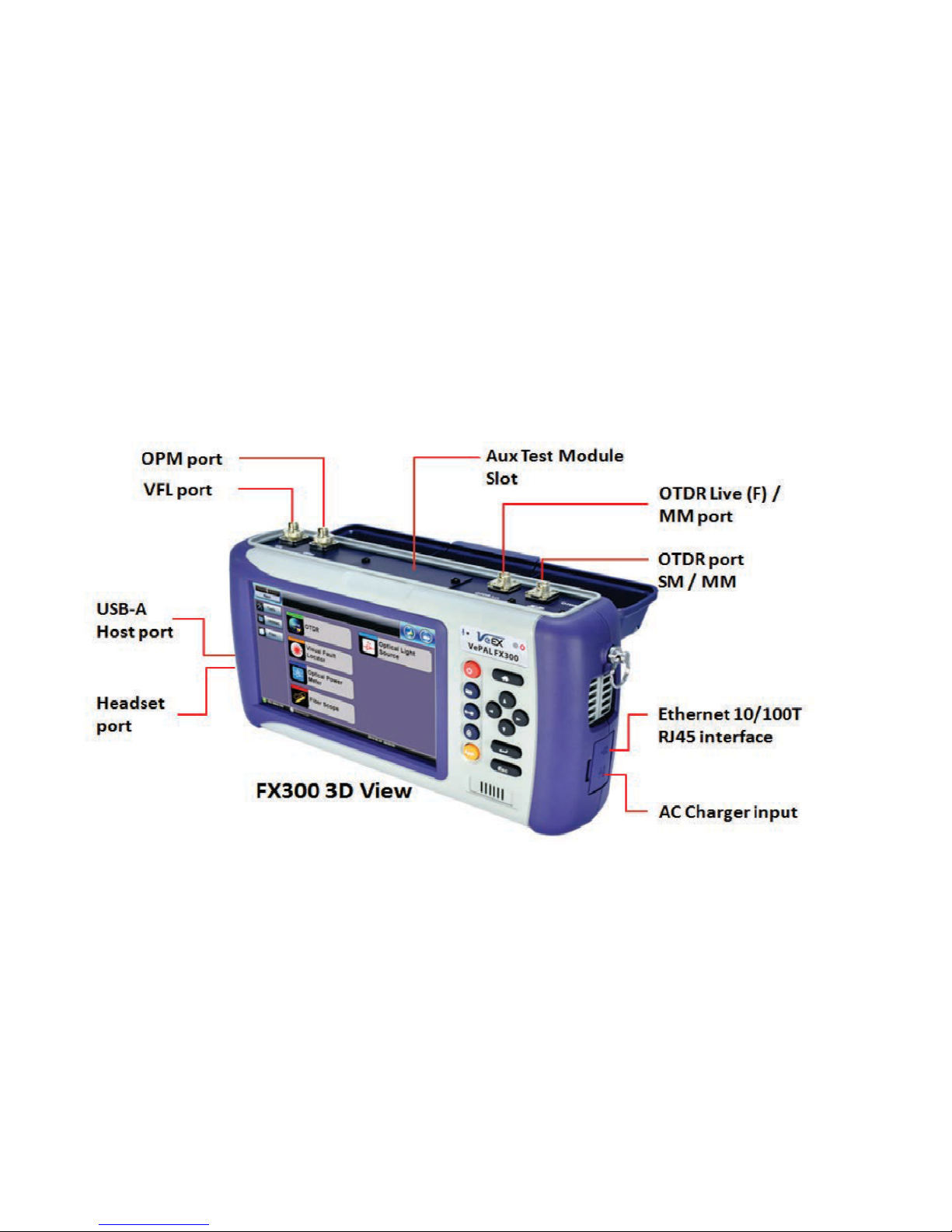
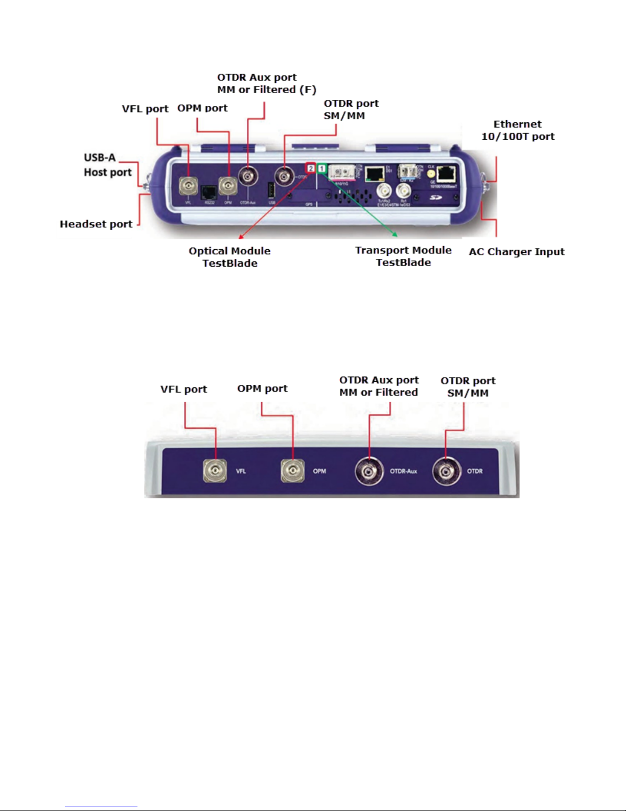
5.1 Test Ports and Interfaces
OTDR testing: The optical fiber under test is connected to either the OTDR or OTDR Aux
(Filtered SM or MM) port on the top panel. The type of the optical fiber connector must
correspond to the OTDR connector or adaptor type, including the connector polish.
Optical Power Meter (OPM) testing: The optical fiber is connected to the OPM port on the
top panel. Depending on fiber connector type, use interchangeable adaptors. FC, SC, ST or
LC type are supplied standard.
Visual Fault Locator ((VFL) testing: The optical fiber is connected to the VFL port on the top
panel. The VFL interface is fitted with universal 2.5mm sleeve accepting all 2.5 mm connector
ferrules.
Note:
Optical Connections - The optical fiber connector must be cleaned prior to connecting to the
fiber under test. Dust and dirt severely impacts optical performance.
Refer to Fiber handling procedures for cleaning tips and information.
OTDR Series e-Manual, D07-00-076P-RevC00 Page 13 of 107
TTXX330000ssTTooppVViieeww
RRxxTT--44110000OOTTDDRRMMoodduullee
OTDR Series e-Manual, D07-00-076P-RevC00 Page 14 of 107
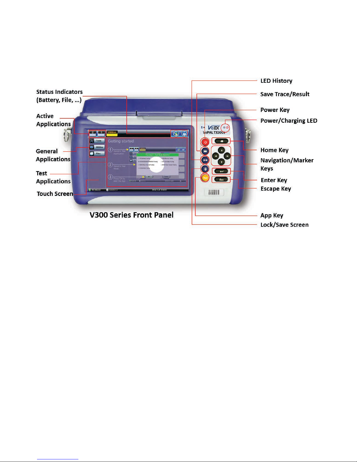
5.2 Front Panel Layout
The picture below depicts the TX300s. Layout will vary depending on FX150, FX300, MTTplus,
or RXT platforms.
5.2.1 LED Indicators
Power/Charge LED - indicates battery charging is in progress. LED turns off when battery is
fully charged.
Note: The device is powered from the built-in Li-Ion battery and can be operated with the AC/
DC adaptor plugged in.
5.2.2 Rubber Keypad
• Home Key: Resets user interface to Main menu
• Navigation/Marker Keys: Used to move markers or navigate menus (in the event
touch screen is disabled for any reason) Enter Key: Enters the desired value or selects
active menu, check box or radio button
• Escape Key: Exits the menu
• App Key: Toggles between active test applications (OTDR, OLS, OPM, VFL)
• Lock/Save Screen Key: Locks the touch panel or saves the screen (bmp) depending
on setting defined in Utility menu
• LED History Key: Resets LED condition (depends on test application)
• Save Trace/Result Key: Saves test result file (OTDR, OPM, Ethernet, Fiberscope -
depends on active application and unit configuration)
OTDR Series e-Manual, D07-00-076P-RevC00 Page 15 of 107
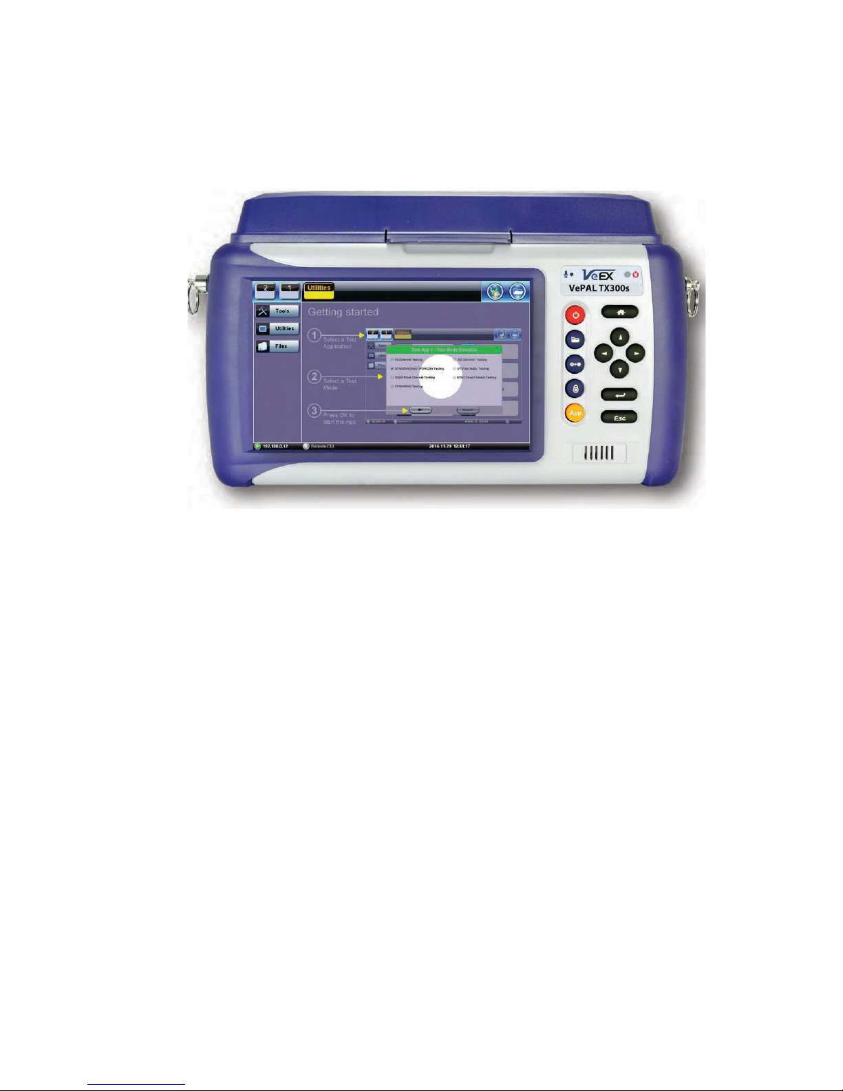
5.2.3 Menu Navigation
Navigate between test applications, setup menus, tabs, or active functions using the supplied
stylus or by using up/down arrows followed by “Enter.”
“Getting started” information is displayed after power up.
Select a Test Application
• FX150: Application #1 is loaded by default. Select OTDR, VFL, OPM, OLS by clicking
the icon on the main menu. The Fiberscope icon can be found on the Advanced Tools
screen.
• TX300s: Select Application 2, which corresponds to the optical test function blade #2,
located on the top connector panel. Select OTDR, VFL, OPM, or OLS by clicking the
icon on the main menu
• FX300/MTTplus/RXT: Select Application 1, which corresponds to the module, inserted
into the module slot. Select Fiber testing from the Test mode selection and press OK.
The OTDR, VFL, OPM, and OLS test functions will be displayed on the main menu.
Note:
Touch Screen Navigation - The unit is equipped with a state of art, full color, LCD TFT touch
screen. When used properly, the screen is designed to give years of reliable and precise
operation. Always use the stylus supplied with the unit to operate the touch screen. Never use
any sharp object such as a ballpoint pen, screwdriver, or similar item as this will damage the
screen and void the warranty.
OTDR Series e-Manual, D07-00-076P-RevC00 Page 16 of 107
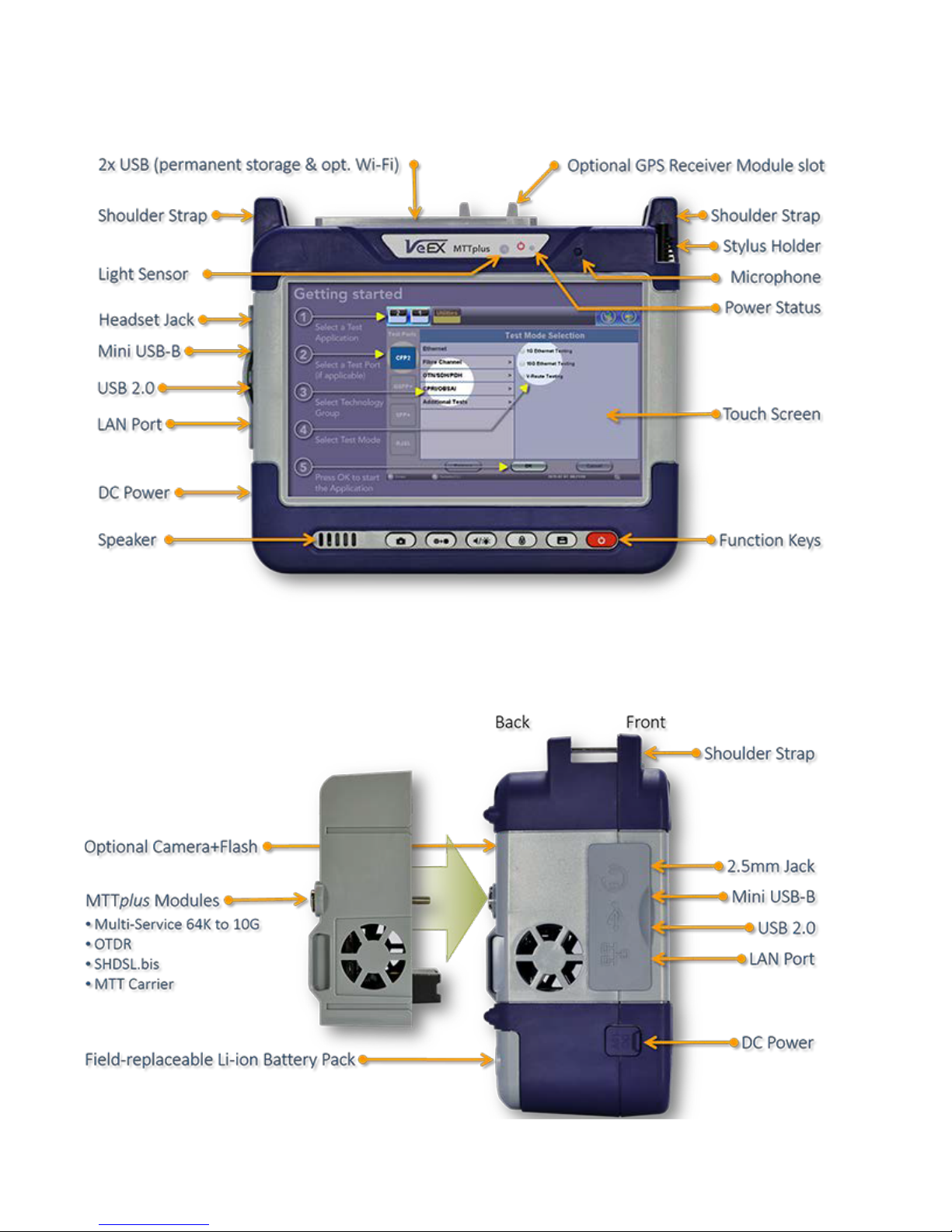
5.3 MTTplus Overview
5.3.1 MTTplus Side View
OTDR Series e-Manual, D07-00-076P-RevC00 Page 17 of 107
option).
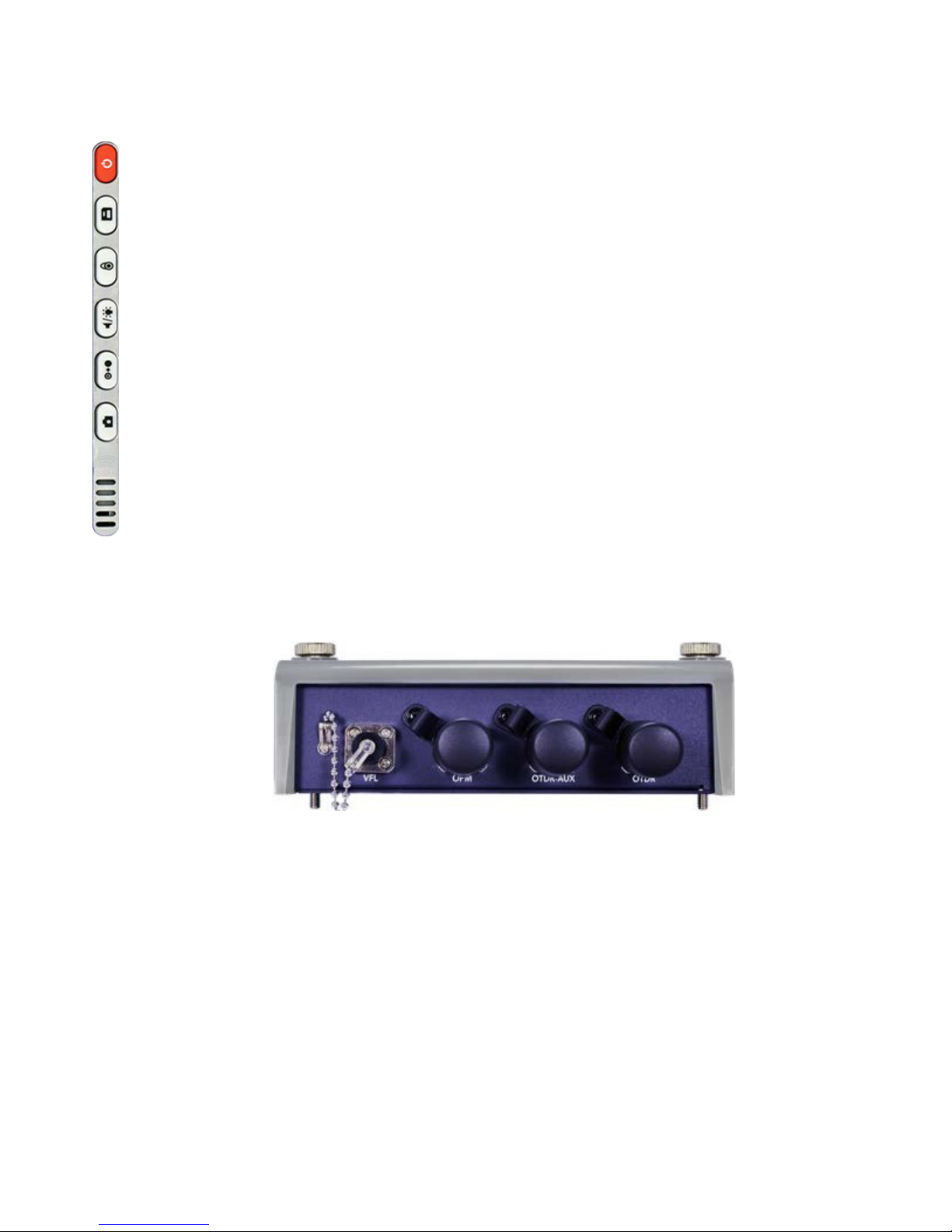
5.3.2 MTTplus Control Panel
• Power: Press for 2 seconds to turn the test set ON or OFF (prevents
accidental ON/OFF) If a test is running when the power off is started, test
is terminated and results may not be automatically saved.
• Save Test Results: Saves the current Test Results with customized or
auto naming.
• Lock/Unlock Touch Screen or Screen Capture: Can also be
programmed to Capture Screen images. Go to >Utilities >Settings
>Global >Save Settings to set save and image compression options.
• Volume and Brightness Control: (it also acts as the MTT F1 key, when
the is active) Brings up the Sound and screen Brightness controls; Use
cursor buttons to adjust the levels.
• Clear History: Resets blinking LED reminders of past Errors or Alarms
Test results are not affected. (not used with OTDR)
• Camera App: Launches the optional Camera App to help document the
job site, damage, connections, etc. Requires the camera (factory-installed
5.3.3 MTTplus OTDR Module Top View
OTDR Series e-Manual, D07-00-076P-RevC00 Page 18 of 107
5.4 RxT Overview
OTDR Series e-Manual, D07-00-076P-RevC00 Page 19 of 107
affected. (not used in OTDR)
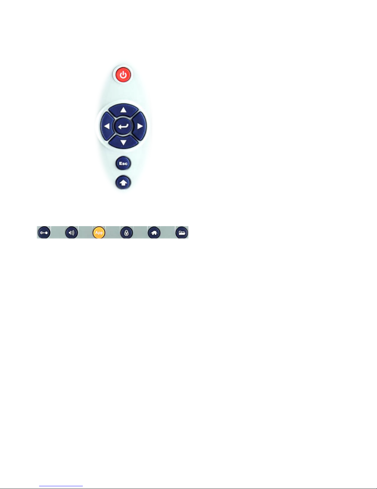
5.4.1 RxT Front Panel
• Power: Press for 2 seconds to turn
the test set ON or OFF (prevents
accidental ON/OFF)
• Cursor Keys: Application
dependent; May offer alternative
GUI Navigation to touch screen
(e.g. while wearing gloves in cold
weather)
• Enter: Application dependent
• Escape: Application dependent
• Alt Alternate function: Links the
buttons to the GUI soft Function
Keys (MTT Emulation Mode only)
• Clear History: Resets blinking
LED reminders of past Errors or
Alarms. Test results are not
• Volume and Brightness Control:
(it also acts as the MTT F1 key,
when the Alt key is active) Brings
up the Sound and screen
Brightness controls; Use cursor
buttons to adjust the levels
• Test Application Selector (it also
acts as the MTT F2 key, when the
Alt key is active): Quickly switches
back and forth between the active
Test Application and RXT platform.
Utilities functions; Active test is not
affected.
• Lock/Unlock Touch Screen: Can
also be programmed to capture
Screen Shots (>Utilities
>Settings>Global>Save Settings)
• Home: Quickly bring users back to
the Main Menu
• Save Test Results: Saves the
current Test Results with
customized or auto naming format
OTDR Series e-Manual, D07-00-076P-RevC00 Page 20 of 107
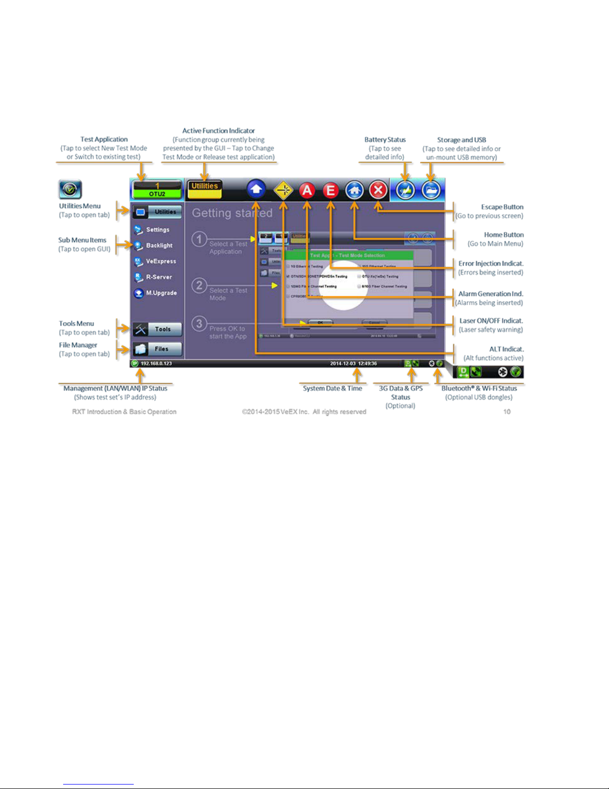
5.4.2 Getting Started
A Quick Guide is always present in the Home screen after boot up.
This screen can be displayed at any time from any screen.
The test port group is assigned to the Fiber application when the 410 module is installed. All
options associated with the 410 OTDR module will be installed.
OTDR Series e-Manual, D07-00-076P-RevC00 Page 21 of 107
Main menu
5.5 FX150 Overview
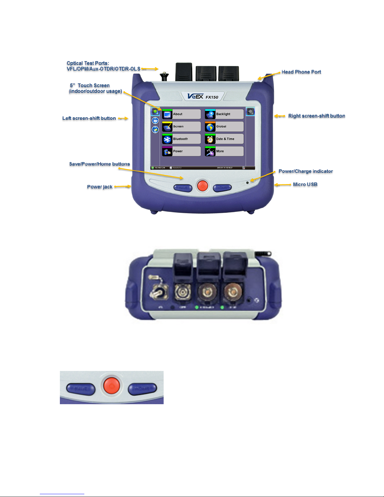
5.5.1 FX150 Test Ports
5.5.2 FX150 Keypad
FFXX115500PPllaattffoorrmm
VVFFLL//OOPPMM//AAuuxx--OOTTDDRR//OOTTDDRR--OOLLSS
• Save: Saves the screen (bmp)
• Power: Press for 2 seconds to turn
the test set ON or OFF (prevents
accidental ON/OFF)
• Home: Resets user interface to
OTDR Series e-Manual, D07-00-076P-RevC00 Page 22 of 107
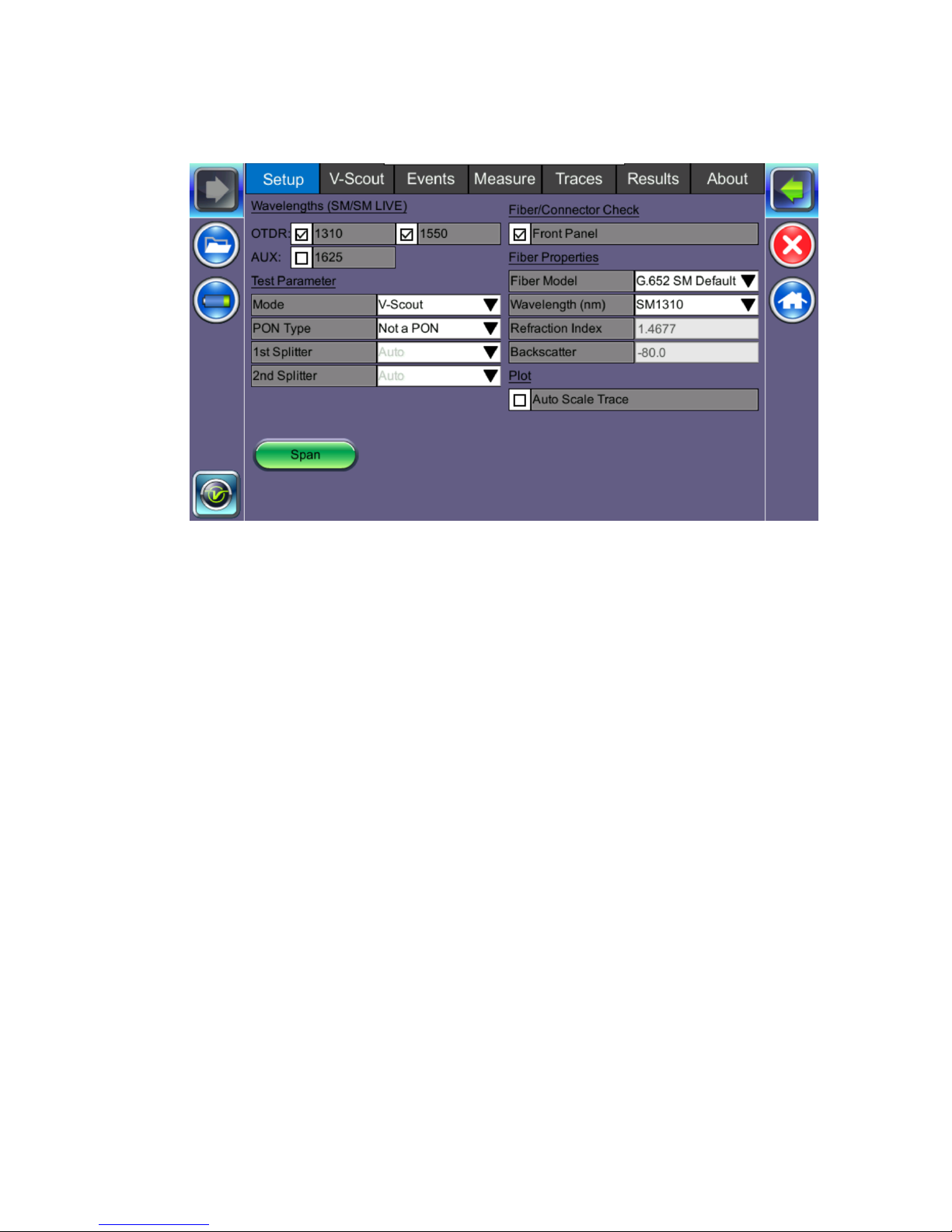
5.5.3 FX150 Screen Navigation
OOTTDDRRSSccrreeeenn
Use the top tabs of the FX150 screen to access test measurement controls and view results.
On the bottom bar, you can see:
• IP address, when connected
• Remote control connection status
• Date and time
• Bluetooth and WiFi connection indicators
OTDR Series e-Manual, D07-00-076P-RevC00 Page 23 of 107
access the Utilities screen.
screen.
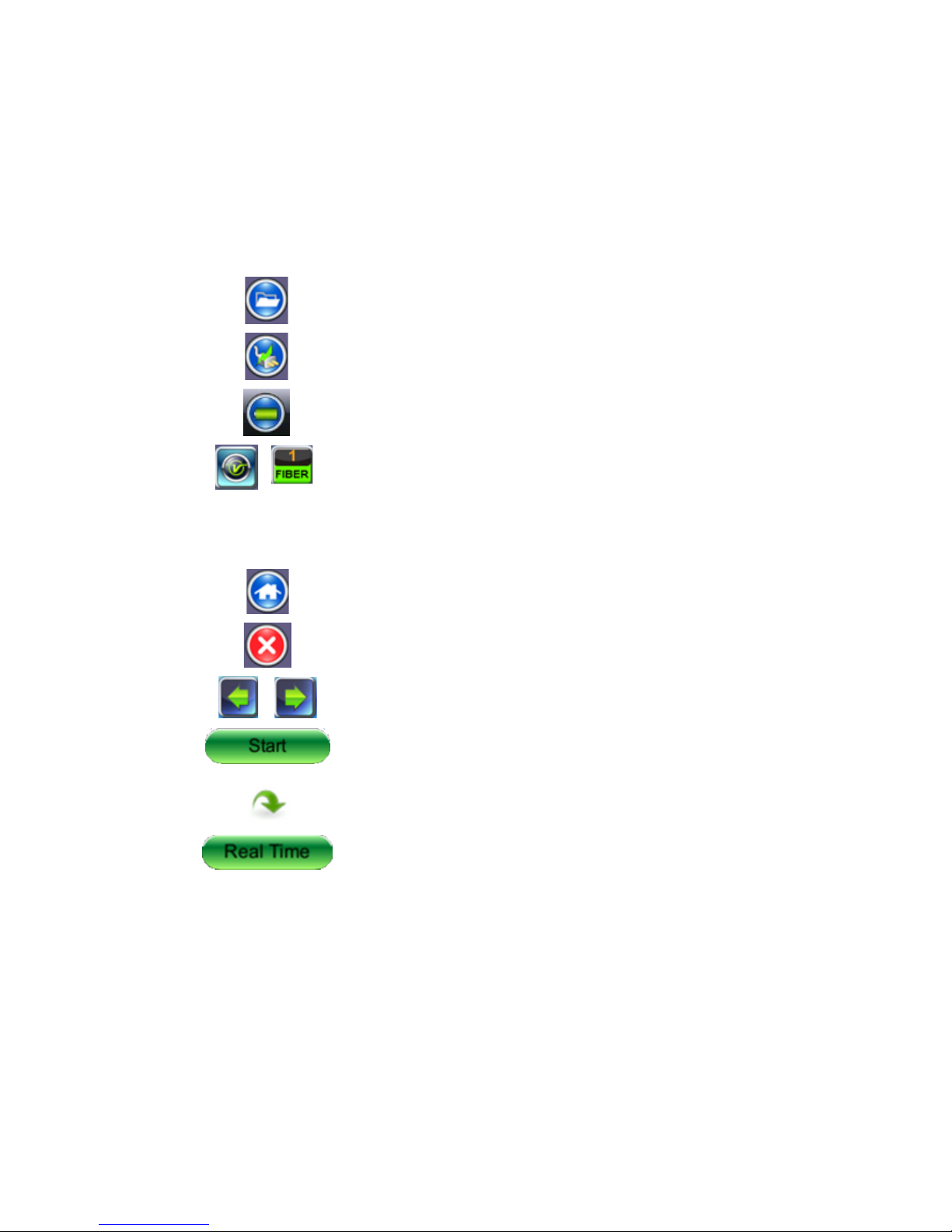
5.5.3.1 View/Hide side menu panels
The left and right panels of the display provide icons to access key functions of the FX150.
These panels can be turned on or off to enable a better view of the application screens.
Use the shift keys located on the left and right sides of the unit to toggle on/off the left
and right menu panels.
Press the LEFT SHIFT KEY to access:
File Storage – Tap to see the size and current capacity
of the internal SSD storage.
Power Source Indicator– Indicates when unit is
powered by external AC power and battery charging
level. Tap to see battery charge status.
V key / Fiber – Tap to access all Fiber Test Modes or
Press the RIGHT SHIFT KEY to access test control buttons and the following:
Home – Tap to return to the OTDR Main Menu.
Escape/Exit – Tap to return to the previous screen.
Arrow – Tap to enter the unit System Settings and Tools
Start – Begin trace.
Green arrow – Switch λ active trace
Real Time OTDR – See trace in real time.
OTDR Series e-Manual, D07-00-076P-RevC00 Page 24 of 107
5.5.4 Setting up FX150 WiFi
The FX150 unit contains an optional built-in WiFi interface allowing you to easily transfer
OTDR traces and upgrade software on the unit.
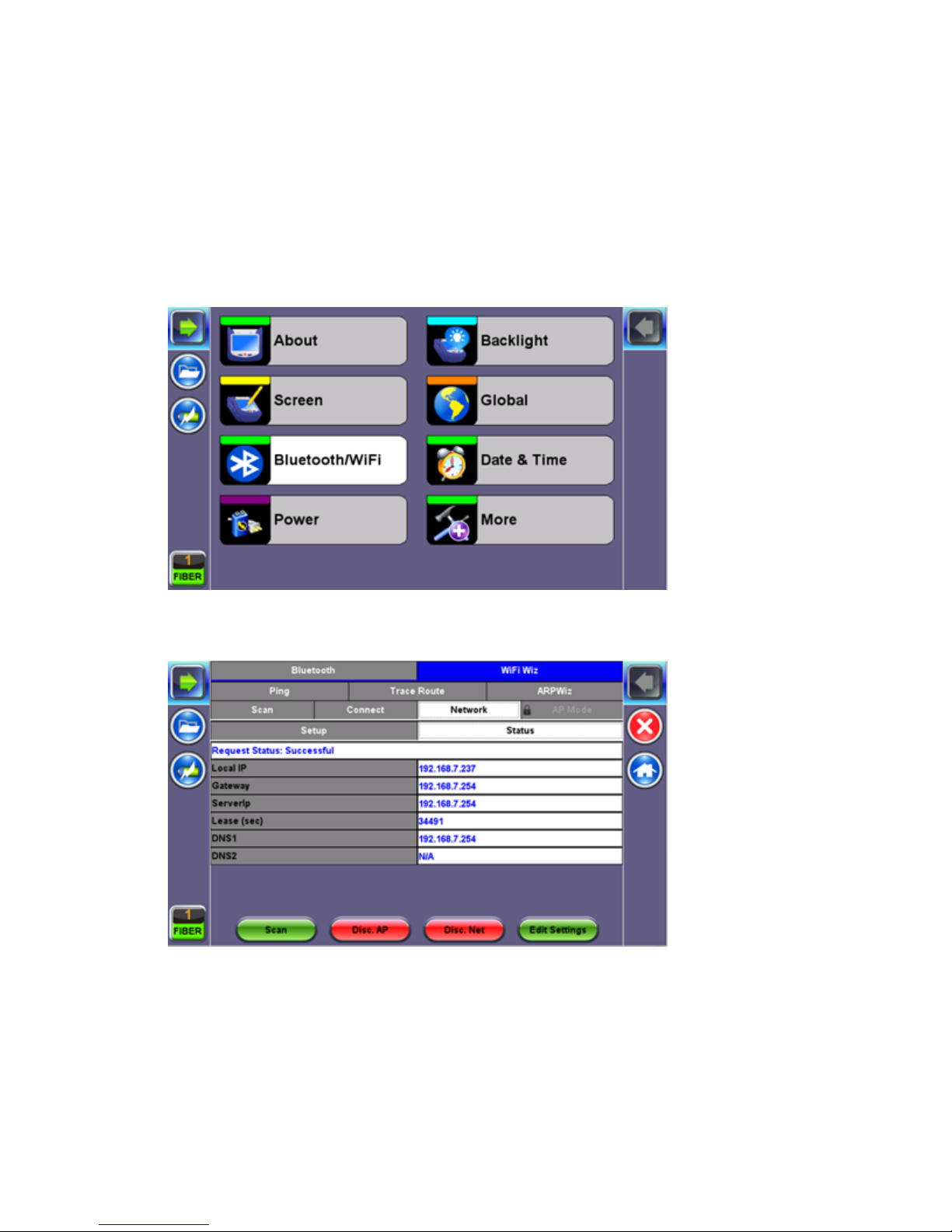
5.5.4.1 Access WiFi option
1. Press Utilities or the HOME key, and then press Bluetooth/WiFi.
2. Select the WiFi Wiz tab.
OTDR Series e-Manual, D07-00-076P-RevC00 Page 25 of 107
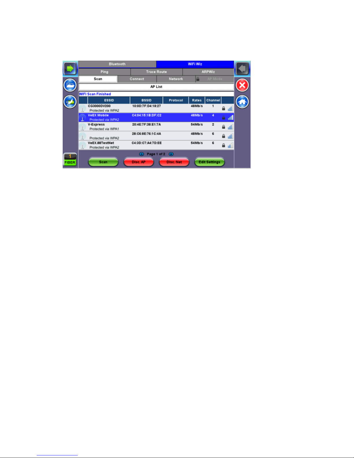
5.5.4.2 Connect to a WiFi network
1. Press Scan to see all networks
2. Select one of the available networks and the Edit Settings key will appear to the right.
Once selected, an Edit Settings function key appears to the right.
3. Tap on Edit Settings to change the Encryption Type and enter the WiFi Key or Connect
AP. The label will change to Disc. AP upon successful connection and the Connect Net
key will appear.
Encryption Type: Supported encryption types include WEP, WPA, and WPA2.
Password: Security phrase or password necessary to access SSID and network. Tap the
Password field to enter the network password on the pop-up keypad (ASCII formatting
supported).
4. Press Apply after selecting the Encryption Type and entering the Key.
5. If the encryption menu was accessed via Connect AP, the test set will connect to the AP
automatically after hitting Apply.
6. If the encryption menu was accessed via Edit Settings, press Connect AP to connect to
the AP.
7. After a successful connection to the Access Point, press Connect Net to obtain an IP
address and access the additional IP tests like Ping, Trace Route etc.
Note: Passwords are case sensitive. If the user enters the wrong network key, the test set will
still connect to the Access Point, but will not be able to connect to the web or perform the Ping
test.
OTDR Series e-Manual, D07-00-076P-RevC00 Page 26 of 107
5.6 Customizing Your Tester
You can customize the settings on your OTDR device in the Utilities>Settings menu:
• About: Displays serial #, MAC address, software version, software options installed and
related product information
• Screen: Displays calibration menu.
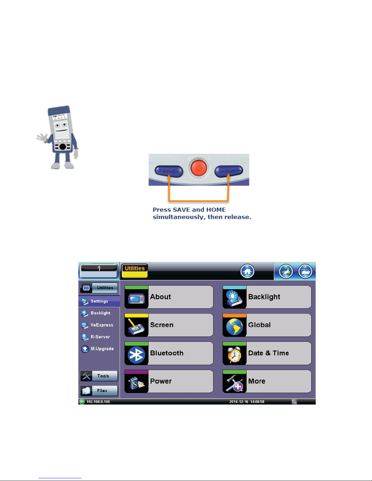
Activating Touchscreen Calibration Mode
You can activate the Touchscreen Calibration Mode using the
keypad by pressing SAVE + HOME keys simultaneously, then
releasing. Press SAVE + HOME again to start a new calibration.
• Backlight: User defined settings when unit is used on Battery or AC power including
Brightness settings

OTDR Series e-Manual, D07-00-076P-RevC00 Page 27 of 107
• Global: Various settings including:
• General
• Language: English, German, French, Chinese, Japanese, Korean and others (de-
pends on software version). You must reboot the device to fully activate the new
language
• Unit: Metric or US
• Audible alarm: sounds alarm when battery runs low or other alarm condition is met
• Show Password: Shows/Hides password in IP setups and other menus where
password is displayed.
• User Interface: International or USA
• WiFi Auto Connect: On or Off
• Auto Color Scheme: On or Off
• RTU-410 (OTDR) Emulation Mode: On or Off
• OTG Port Mode: Host or Device
• Telnet: On or Off
• Share Result: On or Off
• Storage Settings
• File name prefix (for setting prefix for OTDR sor files or other test results):
• Profile deleting: Auto or Prompt user before Deleting
• Profile saving: Auto or Prompt user before Overwrite
• Result saving: Manual or prompt user before saving
• Advance saving: Enables/Disables advanced saving properties
• Save Settings
• Lock/Save Screen: Lock Screen or Save Screen (compression level and maximum
number of screenshots that can be saved.
OTDR Series e-Manual, D07-00-076P-RevC00 Page 28 of 107
6.0 Test Fiber and Initial Preparation Introduction
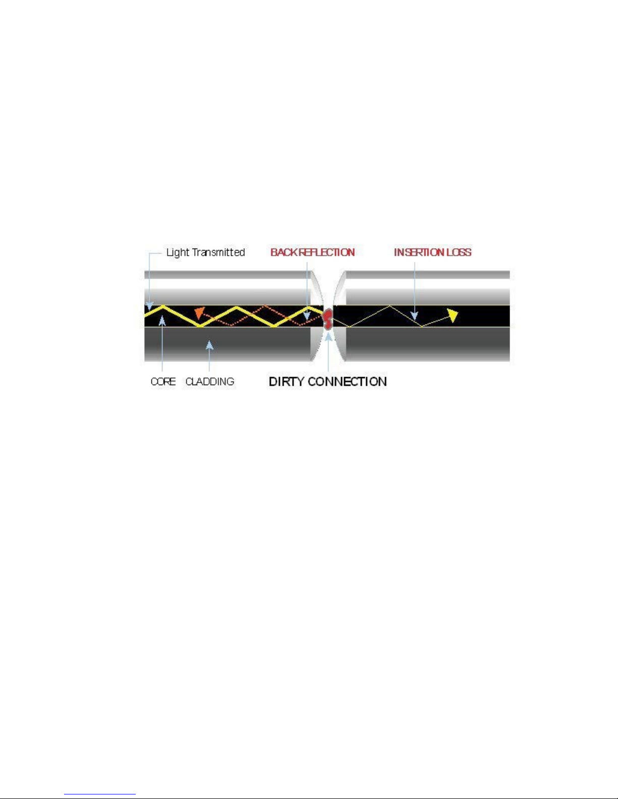
Dirt, dust, and other contaminants severely impact high-speed data transmission in optical
fibers and dirty connector end-faces are often the #1 cause of link failures. High insertion loss
and/or high back reflection can result in transmission loss or high bit errors and poor BER.
Furthermore, most measurement variations and test repeatability conditions in fiber-optic
systems can be traced back to the cleanliness of optical connections. Contamination of fiber
end faces not only affects optical power levels but also impacts back reflectance performance
and levels which is harmful to sensitive optical components.
OTDR Series e-Manual, D07-00-076P-RevC00 Page 29 of 107
6.1 Contamination
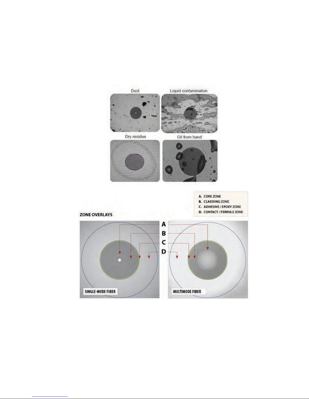
Optical connectors are susceptible to contamination from air borne particles and human body
oils when exposed. Left over liquid residue from improper cleaning can also leave the fiber end
face contaminated. The smaller the fiber core, the more severe the problem is likely to be,
especially when you consider that fiber core diameters can range from 62.5 microns all the
way down to 8 microns in size. Below are some examples viewed by a 400x Fiber microscope:
6.2 Inspection
Whenever possible, inspect the fiber-optic connection (connectors, bulkheads, and test
interfaces) with a fiber microscope. It is recommended to wear laser safety glasses when you
work with fiber-optic connections, and always check that you disconnect the laser or
transmitter before you begin cleaning the connector end faces.

OTDR Series e-Manual, D07-00-076P-RevC00 Page 30 of 107
6.3 Cleaning Procedure
To ensure proper and effective cleaning of optical fiber connectors and interfaces, please
equip yourself with the following cleaning materials:
• Isopropyl alcohol
• Lint free soft tissues
• Ferrule cleaners (1.25mm and 2.5mm versions)
• Connector reel cleaners (CleTop or similar)
Procedure
1. Dab the contaminated connector end-face with a wipe that has been dampened with
Isopropyl alcohol - the solvent will dissolve and remove contaminants that have dried and
attached to the connector or fiber end-face.
2. Rub the fiber end-face perpendicularly against a dry lint free wipe several times.
3. Alternatively, use compressed air to dry the surface quickly. Do not blow or allow the
connector end face to air dry as this may leave a residue behind which is often more
difficult to clean and which can attract even more dirt.
4. Re-inspect the fiber end-face with an optical microscope to check that all the contaminants
have been removed properly - if not, please repeat the process.
Note:
Using Compressed Air - In some clean air situations, you can use filtered air, which is free of
oil and moisture to remove debris and clean a fiber optic connection. However, unless you
follow very strict cleaning procedures, air-driven contaminants can cause more problems.
If you need to use compressed air, hold the can upright. If the can is held at a slant, propellant
could escape and dirty your optical device. First spray into the air, as the initial stream of
compressed air could contain some condensation or propellant. Such condensation leaves
behind a filmy deposit.

OTDR Series e-Manual, D07-00-076P-RevC00 Page 31 of 107
6.4 Best Practices
• Never touch the end face of an optical fiber connector with your hands or fingers.
• Always install dust caps on unplugged fiber connectors.
• Store unused dust caps in a re-sealable plastic bag to prevent dust accumulating.
• Never re-use optic cleaning swabs or lint free wipes. Always discard materials that have
been used.
• Ensure all alcohol or solvent residues are removed after using wet cleaning techniques
• It is recommended to re-inspect the bulkhead receptacles and connector end face using
a fiber microscope following the cleaning and prior to use.
• The flow diagram below describes a best practice prior to connecting your optical fiber.

OTDR Series e-Manual, D07-00-076P-RevC00 Page 32 of 107
6.5 Connectors
6.5.1 Connector Types
In fiber optic networks, you will come into contact with many different connector types, the
most common being described below:
ST Connector
ST stands for Straight Tip-a quick release bayonet style connector developed by AT&T. STs
were predominant in the late 80s and early 90s and are still one of the most commonly used
fiber optic connectors in networking applications. They are cylindrical with twist lock coupling,
2.5mm keyed ferrule.
ST connectors are used both short distance applications and long line systems. The ST
connector has a bayonet mount and a long cylindrical ferrule to hold the fiber.
FC Connector
FC stands for Fixed Connection - it is fixed by way of a threaded barrel housing. FC
connectors are typical in test and measurement environments and for single- mode
applications.
FC is the fiber optic connector standard for Nippon Telephone & Telegraph (NTT) installations,
developed with Nippon Electric Co. (NEC).
Note: The FC screws on firmly, but make sure you have the key aligned in the slot properly
before tightening.

OTDR Series e-Manual, D07-00-076P-RevC00 Page 33 of 107
LC Connector
LC stands for Lucent Connector. It is a small form-factor fiber optic connector that uses a 1.25
mm ferrule, which is half the size of the ST / SC connectors.
It uses a standard ceramic ferrule connector. The LC has good performance and is highly
favored for both multimode and single mode applications, especially in high-density connector
facilities. The LC connector is available in simplex or duplex cables.
SC Connector
SC officially stands for Subscriber Connector; however, some people believe that “Square
Connector,” is the correct name. It is a general purpose push/pull style connector. It was
developed by NTT, which has an advantage in LAN/enterprise networks where duplex cabling
to support TX/RX channels are commonly used.
SC Connectors are frequently used network applications. The connector is square and keyed
with push-pull mating, 2.5mm ferrule, and molded housing for protection. The SC is a snap-in
connector that is widely used in singlemode systems due in part for its performance. The snapin connector latches with a simple push-pull motion.

OTDR Series e-Manual, D07-00-076P-RevC00 Page 34 of 107
E2000 Connector
Developed by Diamond, this connector has proven its performance worldwide in CATV and
telecommunication networks. The connector features a spring-loaded shutter used to protect
the ferrule from dust and scratches, and to provide increased safety protection. It uses a high
precision Zirconia full ceramic ferrule with an insertion loss of 0.1dB. The APC version has a
return loss of better than 85dB. The connector is especially suited for installation in global high
performance networks.
The E2000 patchcords is available in simplex and duplex versions and comply with IEC 61
754-15 and TIA/EIA 604-16 standards
6.5.2 Connector Performance and Polishing
Polishing of fiber optic connectors is the process of polishing the end-face of the ceramic
ferrule within the fiber optic connector. The purpose is to improve the light transfer between the
mating of connectors, in order to minimize optical losses and reducing reflections. This is an
important aspect of fiber optic communications as losses affect the quality of the light signals.
There are two main types of losses that are affected by the style and quality of polishing, which
dictate the optical performance level of terminated fiber optic connectors:
• Insertion Loss (IL) - The most important performance indicator of a fiber optic
connection. This is the loss of light signal, measured in decibels (dB), during the
insertion of a fiber optic connector.
• Return Loss (RL) - Also known as back reflection, is the portion of the light signal that
is reflected back to the original light source. This occurs as the light is reflected off the
connector and travels back along the fiber to the light source. This indicator is measured
in negative decibels (dB). When reading return loss figures, the higher the absolute
value of the decibel unit means the better the performance of the interconnection.
The amount of insertion loss is affected by fiber alignment, and/or the quality of the finishing on
the end of ferrule, while reflectance is affected by the style of polishing on the ceramic ferrule
in a connector. There are three different styles of polishing, reflected by their shape of the
finish:
• Physical Contact (PC) - In the PC style finish, the fiber is polished to a smooth curve.
As the name implies (i.e. physical contact), the ferrules of adjoining fibers come into
physical contact and this reduces the air gap between the contacting ferrules, resulting
in lower insertion losses. The smooth curve in the PC style is designed to reduce the
return loss by reflecting the light out of the fiber. However, the PC polishing style incurs
more return loss than other styles.

OTDR Series e-Manual, D07-00-076P-RevC00 Page 35 of 107
• Ultra Physical Contact (UPC) - The UPC style ferrule has the shape of the PC style,
except they are polished with several grades of polishing film that allows for an ultrasmooth surface. The main difference between UPC and PC is that the former have
lower return loss.
• Angled Physical Contact (APC) - The APC style produces the lowest return loss when
compared to other styles. The ferrule is polished to an angle of 8 degrees. The angle is
calculated so that it is less than the critical angle, which ensures light is not propagated
back along the fiber.
Connector Polish and Performance
Typical Return loss values are:
Polished Connector ~ -45dB
Ultra-Polished Connector ~ -55dB
Angled Polished Connector up to ~ -65dB

OTDR Series e-Manual, D07-00-076P-RevC00 Page 36 of 107
6.6 Fiber Cables and Fiber Patchcords
6.6.1 Fiber Cable
Styles of Fiber Optic Cable vary in outer appearance, materials, application, features, and
benefits. In OTDR applications, you will regularly come across the following types:
Bare Fiber
• Usually Spooled in 25km spools
• 250 to 400um acolyte buffer / polyimide
• PM Light Sensitive Bare
• Fiber Adaptor is a useful accessory and provides quick connection to check fiber
length/continuity
PVC or Plenum Jacketed
• Many colors that mean very little
• Used mostly in internal applications
900um
• Patchcords
• Simplex (single fiber) or Duplex (two fibers) construction
• Singlemode or Multimode
• Pig tails
• Outer Diameter is usually 1.6mm, 2.0mm, and 3.0mm
• Duplex versions - Zip cord with outer diameters of 1.6mm, 2.0mm, 3.0mm
Break Out
• Both Multimode and Singlemode
• Indoor / Outdoor applications
• 1.6mm, 2.0mm, and 3.0mm sub units
• 2, 4, 6, 8, 12, 24, 48, 72 or greater fiber counts Outer Jacket can be of a variety of
materials
• Terminated with all styles of connectors
• Often field terminated
Distribution
• Both Multimode and Singlemode
• Indoor / Outdoor applications
• 900um sub units

OTDR Series e-Manual, D07-00-076P-RevC00 Page 37 of 107
2, 4, 6, 8, 12, 24, 48, 72, 144 or greater fiber counts
• Outer Jacket can be of a variety of materials
• Usually longer runs and can be terminated with almost any style of connector
Ribbon
• Commonly used in LAN and PON applications with MTP/MPO connectors
6.6.2 Fiber Patchcord
A fiber patch cord is a piece of fiber cable that is used to connect the OTDR to the fiber under
test. In a typical installation, fibers comprising the incoming cable will be “broken out” and
terminated in a patch panel or wiring closet. One end of the patch cord is usually connected to
the OTDR while the other end is progressively moved along the patch panel as measurements
are made on each fiber.
The patchcord plays a critical role in fiber measurements and users should ensure that a high
quality patchcord is always used, because this can and will have profound performance on test
results and traces.
Factors affecting the choice of patchcord include:
• Fiber type – singlemode, multimode or ribbon
• Connector type (ST, SC, FC, LC, E2000, MTP/MPO, etc.)
• Dead-zone requirements (Refer to Section 4.2) Back reflection performance
• Insertion Loss
• Durability and Longevity
• Bend Limitation

OTDR Series e-Manual, D07-00-076P-RevC00 Page 38 of 107
Color Code of Jacket
Definition or Meaning
Yellow
Singlemode fiber
Orange
Multimode fiber
Aqua
10G laser-optimized 50/125um multimode optical fiber
Grey
Obsolete color code for multimode fiber
Blue
Sometimes used to designate polarization maintaining fiber
Color Code of Connector Boot
Definition or Meaning
polarization-maintaining optical fiber.
Singlemode only, not available for multimode fibers
Black
Physical Contact (PC), 0°
White
Physical Contact (PC), 0°
Raman pumps
Color Coding
The buffer or jacket on patchcords is often color-coded to indicate the type of fiber used.
Connector boot
The strain relief “boot” that protects the fiber from bending at a connector is color-coded to
indicate the type of connection.
Connectors with a plastic shell (such as SC or E2000) typically use a color-coded shell.
Standard color coding for jackets and boots (or connector shells) are shown below:
Blue Physical Contact (PC), 0°
Mostly used for singlemode fibers; some manufacturers use this for
Green Angle Polished (APC), 8°
Red High optical power. Sometimes used to connect external pump lasers or

OTDR Series e-Manual, D07-00-076P-RevC00 Page 39 of 107
6.7 Inserting the Fiber
Carefully align the optical fiber connector to the port to avoid rubbing the fiber against the
external part of the port or any other surface. If the interface of the connector has an alignment
key, make sure to insert it correctly into the corresponding groove.
Push the connector in and make sure the optical cables are inserted to guarantee sufficient
contact. If the connector has screw bushing, screw down the connector to fix in the optical
fiber. Do not over-screw the connector or it will damage the optical fiber and the port.
6.7.1 Preventing Inaccurate Readings
To achieve maximum power and prevent false readings, clean the optical fiber connector
interfaces before inserting them into the test port.
Please ensure the correct fiber connector type is used before inserting it into the test port or
connector. Mismatched connector types will damage the optical end faces and the test set.
Note: If the optical fiber is not aligned properly and/or completely connected, it will
cause serious loss and reflection.
6.8 Fiber Scope Utility (FX150, FX300, MTTplus, RxT)
6.8.1 Fiber Scope Overview
DI-1000 Digital Fiber Scope
The DI-1000 uses auto focus and capture the image and grade the connector’s health and
cleanliness after it is polished or cleaned. It is compatible with the FX300, RX-1200, and
TX300S platforms.
VS-500 Video Fiber Scope
The VS-500 features a single-finger focusing knob, brightness control, and a digital sensor with
detectable resolution to 0.5 µm. It is compatible with the FX300, MTTplus, RXT-1200, and
TX300S platforms.

OTDR Series e-Manual, D07-00-076P-RevC00 Page 40 of 107
6.8.2 Connecting the Fiber Scope
Note: VS-400D, VS-500 and DI-1000 Fiber Inspection Scopes are currently supported if the
Fiber Scope Expert option is installed.
1. Connect the Fiber Scope to the test set, using any available USB port (Older analog fiber
scopes require a USB adapter). To connect to the FX150 microUSB port, use an approved
OTG cable.
2. Select the Utilities or button on the top-left corner of the screen.
3. Tap the Tools menu item, and then tap Advanced Tools.
4. Select the Fiber Scope options.
Note: The OTDR Viewer app is for the portable USB/Bluetooth OPX BOX micro
OTDR option. The Optical Power Meter app is for the UPM-100 USB dongle option.

OTDR Series e-Manual, D07-00-076P-RevC00 Page 41 of 107
6.8.3 Setup
• File Prefix: Enter any name to identify the cable, site, technician, job, etc.
• Starting #: Enter the initial sequence number. This number will increase with each
image captured.
• Scope mode: Select Local or Remote operation.
6.8.4 Analysis
To begin the analysis:
• Select the Connector Analyze Profile and press the green Activate button.
Note: Currently, no IEC Analysis is available for MTP/MPO connectors.

OTDR Series e-Manual, D07-00-076P-RevC00 Page 42 of 107
6.8.5 Capture Screen
• Freeze / Resume: Stops the real time video so users can look at the static picture.
• Analysis On / OFF: Turn the Auto Analysis ON and OFF (software option).
• Auto Freeze: Turn On and OFF the ability to freeze the image automatically, when in
Focus.
• Rectangles / Dots: Dots draw a red contour around scratches and defects. Rectangles
highlight scratches and defects without obstructing the view.
• Shake: Turn On or OFF the ability to Auto Freeze and Analyze when probe image is
unsteady.
• Save: Saves the fiber picture that is on the screen (in Freeze mode) or just Tap the
Screen.
Notes:
1. When the DI-1000 Fiber Scope is plugged into USB, a blue LED will emit. The round
FOCUS knob is on top. Turn right or left to focus.
2. When the VS-400 Fiber Scope is plugged into USB, a white light will emit. The FOCUS
adjustment is located at base of barrel.

OTDR Series e-Manual, D07-00-076P-RevC00 Page 43 of 107
6.8.6 Captured Files
Use check boxes to select one (View) or two (Compare) files.
• Clear All: Deletes all files saved in memory.
• Delete: Deletes all selected files.
• Compare: If two files are selected, they can be compared. For example, pictures of the
same connector before and after cleaning.
• Analyze: Open the connector face analysis feature.

OTDR Series e-Manual, D07-00-076P-RevC00 Page 44 of 107
6.8.7 Connector Face Analysis
Select a file from the Captured Files screen and press the Analysis button.
• Open: Provides a visual navigation tool to select files. Use the stylus to slide left or right
until the correct file is in view, tap on the image to load it.
• Show/Hide Overlay: Enables or disables the analysis mask and defect detection.
• Comments: Add information about the fiber ends, comment about the result, status or
any other meaningful information about connector, application, or case. This information
will be included in the report.
• Save Report: Generates a test report for the selected file (html format). Test set can
convert reports to PDF and send them to USB memory sticks.
• Return: Exit and return to Captured Files Tab.

OTDR Series e-Manual, D07-00-076P-RevC00 Page 45 of 107
6.8.8 Connector Face Analysis Results Table
Select the Result Table tab. The test set displays a table with all numeric results from the
analysis. Catalogs, Defect and Scratch events found for all four zones.
Scratch requirements refer to width.
Note: This table will also be included in the reports.

OTDR Series e-Manual, D07-00-076P-RevC00 Page 46 of 107
6.8.8.1 HTML Report
The Fiber Scope test report can be viewed in HTML format.

OTDR Series e-Manual, D07-00-076P-RevC00 Page 47 of 107
6.8.8.2 PDF Report
The Fiber Scope test report can be viewed in PDF format.

OTDR Series e-Manual, D07-00-076P-RevC00 Page 48 of 107
6.8.9 Managing Fiberscope Results with File Manager
1. Go to Utilities >Files >Saved. All results stored in the test set are displayed.
2. Use the to select the desired files.
3. Tap on any column header to sort by that specific parameter (FS Analysis or Fiber Scope).
Tap again to change the sorting order.
• U/L: Unlock or locks files to prevent accidental deletion.
• PDF: Converts all selected files: Requires FAT32 USB Memory stick.
To backup and restore files, use a USB Memory stick.
• To USB: Copies all selected files to the stick.
• From USB: Restores all files from the stick.
• BT: (Bluetooth®) File Transfer the requires compatible USB dongle.

OTDR Series e-Manual, D07-00-076P-RevC00 Page 49 of 107
6.8.9.1 File Manager Filters
File Filters make it easier to isolate desired types of results from all other test results stored in
the test set. It also reduces the number of pages displayed.
To activate filters, use the stylus to tap the + icon.
Fiber inspection test results belong to Common Mode and Fiber Scope Tests. Filter
parameters can be combined.
To reset filters, press the Show All button.
To make locating test results and reports easier, sort the results by tapping a header to sort by
that field’s type, in ascending or descending order.

OTDR Series e-Manual, D07-00-076P-RevC00 Page 50 of 107
6.8.10 Fiber Scope Image Management Software (ViS400D only)
Detailed PC-based Fiber Inspection Monitor & Analysis: Compatible with VIS400D
• IEC 61300-3-35 Profiles
• SMF UPC >45 dB
• SMF APC
• SMF PC RL>26 dB
• MMF PC
• Manual & Auto Analysis
• Focus level indicator
• Report Generation
• Optical Power Measurement: Compatible with UPM-100 OPM

OTDR Series e-Manual, D07-00-076P-RevC00 Page 51 of 107
6.8.11 Fiber Scope Image Management Software (VS-500 and DI-1000 only)
Detailed PC-based Fiber Inspection Monitor & Analysis: Compatible with DI-1000 Fiber Scope
• IEC 61300-3-35 Profiles
Analysis Profile Parameters:
• AnalysisParam1: SMF UPC >45 dB
• AnalysisParam2: SMF APC
• AnalysisParam3: SMF PC RL>26 dB
• AnalysisParam4: MMF PC
Video Mode:
• Start: Activate Real Time viewing mode
• Stop: Halt Real time viewing mode and display last image
• Analysis: Turn ON/OFF Auto IEC Analysis when image is in Focus
• Shake: Turn ON/OFF Shake function to facilitate auto-freeze and analysis when image
is unsteady
• Rect: Toggle between dot or rectangular marking of events

OTDR Series e-Manual, D07-00-076P-RevC00 Page 52 of 107
• AutoFreeze: Turn ON/OFF Auto Freeze when Fiber Scope image is in Focus
• UnFocus before Freeze: Select if you wish to unFocus Image prior to Freezing image
• Show Table: Select to switch from connector image to Table view
Click the to pop up the File Management Window.
• OpenFile: To View saved files
• SaveFile: To Save Fiber Scope results
• Generate Pdf Report: To save Fiber Scope results in pdf file format.

OTDR Series e-Manual, D07-00-076P-RevC00 Page 53 of 107
• About: To check the Fiberizer Scope software revision for the Fiber Scope
• Exit: To quit the Fiberizer Scope program.

OTDR Series e-Manual, D07-00-076P-RevC00 Page 54 of 107
6.9 Visual Fault Locator (VFL)
The unit is equipped with an optionally built-in Visual Fault Locator (VFL) to trace and visually
identify breaks in ODFs, bare fibers (900 µm), and patch cords that are typically hidden in the
OTDR dead zone.
The VFL works by injecting a 650nm visual red light into the fiber (up to 5 kilometers/3 miles)
to bend a single fiber strand and force light to exit the center of the fiber. It traces it to identify
faults through light leakage. It identifies fiber strands, connectors, breaks, bends and other
potential problems or anomalies on events.
To see the most recent VFL specifications, go www.veexinc.com.
PROTECT YOUR EYES!
Never look directly into the VFL’s light. It is a Class II laser and emits
laser radiation that will harm your eyes.
Use the Home icon (FX150/FX300) or App key (FX300) to toggle between active test
applications (OTDR, OPM, VFL).
VFL can be used with OTDR simultaneously.

OTDR Series e-Manual, D07-00-076P-RevC00 Page 55 of 107
6.9.1 Using the VFL
To operate the VFL:
1. Make sure laser is turned off. Remove connector covers from the cable.
2. Connect the fiber to the VFL port located at the top of the unit. The VFL interface is fitted
with universal 2.5mm sleeve accepting all 2.5 mm connector ferrules.
3. Use Test App 1 – Test Mode Selection Fiber testing to display the VFL App.
4. Press Visual Fault Locator on the main menu. The Caution screen appears.
5. Select the operation mode.
CW: Continuous Wave. Select this option to turn on the VFL continually to check for
faults.
1 Hz: Pulse. Select this option to send intermittent light pulses. In some cases, this
makes it easier to identify faults (than continuous light). It can also be used with audible
detectors (toners) that can identify faint light or in well-lit (bright) environments.
6. Press Auto Off. When VFL application is exited, the VFL powers down automatically.
7. Press Turn ON to power the laser. The Caution box turns yellow.
8. You will observe that a red light emits from the end of the fiber to confirm continuity. This
red light will also appear at splices, joints, connectors, ODLs, etc. if any light is leaking.

OTDR Series e-Manual, D07-00-076P-RevC00 Page 56 of 107
9. Press Turn OFF.
10. Disconnect the cable and replace covers.
When not in use, disconnect the cord from the port, replace dust covers,
and keep the port cap securely closed.
For patchcords with dark cabling or any outdoor cable or bend-insensitive
patchcords (armored cables), VFL will not work because there is no way
to bend fibers.
6.10 Optical Light Source (OLS)
The unit can be equipped with an optional Optical Light Source (OLS) to use in conjunction
with the OPM and test the entire fiber infrastructure. It identifies microbends, bad
splices/connectors, and fiber breaks through visible laser light leakage. Use the automated
feature to control both units at each end and test the fiber (multimode or singlemode) at
different wavelengths. The OLS radiates continuously or in pulses.
To see the most recent OLS specifications, go www.veexinc.com.
PROTECT YOUR EYES!
Never look directly into the OPL’s light. The laser radiation emitted will harm
your eyes.

OTDR Series e-Manual, D07-00-076P-RevC00 Page 57 of 107
6.10.1 Accessing and setting up the Optical Light Source
To access and set up the OLS option:
1. Make sure that the Optical Light Source option is installed on the test unit.
2. Power on the unit. Test App 1 – Test Mode Selection is loaded by default. Select Fiber
testing, and then press OK.
3. Press Optical Light Source on the main menu. The OLS screen appears with the Caution
warning.
4. In the Lasers drop-down list box, select the calibrated wavelength (1550nm/1310nm) to
match the signal being measured.
5. Select the operation mode (CW, 270 Hz, 1000 Hz, or 2000 Hz) for the test.
CW (Continuous Wave): Select to continually measure level, loss, and reflectance
in optical components.
270 Hz, 1000 Hz, 2000 Hz (Pulse). Select this option to send intermittent light
pulses. In some cases, this makes it easier to identify faults (than continuous light). It
can also be used with audible detectors (toners) that can identify faint light or in welllit (bright) environments.

OTDR Series e-Manual, D07-00-076P-RevC00 Page 58 of 107
6.10.2 Using the Optical Light Source
To use the OLS:
1. Connect a patchcord between the OLS and OPM test ports.
2. Select Optical Light Source from the main menu. The OLS screen appears.
3. Tap Turn ON to power on the OLS.
4. If WaveID is available, tap Loop mode, to auto cycle through all available wavelengths on
the test port. The laser will change every three seconds.
5. When testing is complete, tap Turn OFF to power off the OLS, and then disconnect the
cable and replace the port covers.
RXT-4111DWDM OTDR Laser Stabilization
The RXT-4111 DWDM OTDR test module offers advanced TEC laser
stabilization for hot and color weather operating conditions. If the
optimal temperature for usage has not been reached, a Laser
Stabilization message appears.
LLaasseerrSSttaabbiilliizzaattiioonnmmeessssaaggee

OTDR Series e-Manual, D07-00-076P-RevC00 Page 59 of 107
6.11 Optical Power Meter (OPM)
The unit can be equipped with an optionally built-in Optical Power Meter (OPM). It can also
access an external Optical Power Meter using the Micro-USB port. It works by testing average
output power from a light source and can be used to measure the span loss in dB of an optical
fiber systems. On the test set display, view measurement loss in real-time.
Note: Only optical power meters (e.g. Built-in, UPM-100 or FX40 series meters) approved by
VeEX are supported.
To see the most recent OPM specifications, go www.veexinc.com.
Use the Home icon (FX150/FX300) or App key (FX300) to toggle between active test
applications (OTDR, OPM, VFL).
6.11.1 Setting up the Optical Power Meter
To access and set up the external OPM:
1. Make sure the external Optical Power Meter is connected to the Micro-USB port via an
OTG cable.
2. Power on the unit. Test App 1 – Test Mode Selection is loaded by default. Select Fiber
testing, and then press OK.
3. On the Home menu left panel, tap Tools>Advanced.
4. On the main menu, tap Optical Power Meter. The OPM setup screen appears.
Accessing the Optical Power Meter module shuts down GPS and the
atomic service.

OTDR Series e-Manual, D07-00-076P-RevC00 Page 60 of 107
To access and set up the internal OPM:
1. Check the test ports to ensure that the Optical Power Meter option is installed on the test
unit.
2. Power on the unit. Test App 1 – Test Mode Selection is loaded by default. Select Fiber
testing, and then press OK.
3. Press Optical Power Meter on the main menu. The OPM screen appears with the Caution
warning.
See 6.11.2 Using the built-in OPM for information on using the built-in OPM.
6.11.1.1 USB OPM Setup Options
Use the following options to configure the OPM:
• Wavelength: Provides a list of calibrated wavelengths to match the signal being
measured.
• Test Mode: Select between Power or Loss measurements.
• Power Meter (OPM): In Power Meter mode, the test set presents the direct power
readings, which are displayed in dBm, mW or uW units. You can perform unit
conversions by using the dBm, mW or uW buttons.
• Loss Meter: In Loss Meter mode, the test set reports the difference in power
readings between the Laser Source (LS) output being used and what is currently
present at the connector after being attenuated by the fiber. The results are
presented in dB.
Loss meter must be referenced (calibrated) to the Laser Source output.

OTDR Series e-Manual, D07-00-076P-RevC00 Page 61 of 107
To calibrate the Loss meter to the LS:
1. Connect the LS the OPM using a short patch cord.
2. Tap the Reference button to record the 0dB point. A reference point is established and the
calibrated LS can be connected to the far-end of the fiber to measure the loss.
• Hold: Freezes the last power or loss reading on the screen. Hold appears on the white
screen when tapped. Tap Hold again to unfreeze it.
• Save: Records instantaneous power or loss readings in the Results tab. The Save
button must be used to record these individual readings (e.g. same cable at different
wavelength). Use the Folder button to save the complete set of results.
Saving the power or loss readings is useful when measuring multiple
fibers or testing one fiber with multiple wavelengths.
• Reference (Reference Power Level for Loss Meter Test Mode): Sets the output
reference level to measure against when a short and clean optical patch cord for the LS
is connected directly to the unit’s OPM port.
Press Set to store the reading or press Cancel to keep the previously stored value.
6.11.1.2 Setting Pass/Fail Limits
Whether measuring optical power or loss, there are always power input limits (saturation and
loss) or attenuation allowances that determine whether the fiber cable meets the requirements
for the desired application or network elements.
• Power Limits: Select the Power Limits (dBm) checkbox and enter the Minimum and
Maximum power levels allowed for the application (e.g. in line with the transceiver’s
dynamic range). If the power reading falls beyond those limits, the power measurement
reading will turn red.
• Loss Limits: Select the Loss Limits checkbox and enter the Minimum and Maximum
amounts of optical power loss that are acceptable for the application or specified for the
cable or installation. You can specify the total amount of attenuation in dB, or select the
dB/km or dB/mi if the results are being compared against cable specifications. If
needed, enter the Length of the cable under test for the test set to make the
conversion.

OTDR Series e-Manual, D07-00-076P-RevC00 Page 62 of 107
6.11.2 Using the built-in OPM
1. Connect the fiber to the OPM port located at the top of the unit.
2. Power on the unit.
3. Select Test App 1 or Fiber to see the OTDR/VFL/OLS/OPM selection screen.
4. Tap Optical Power Meter. The OPM menu appears.
5. If the light source has a WaveID option, tap Wave ID to detect the wavelength of the
incoming signal automatically.
6. When testing is complete, tap Turn OFF to power down the OLS, and then disconnect the
cable and replace the port covers.
Use the following options to configure the OPM:
• Wavelength: Matches the calibrated wavelength to the signal being measured.
• Wave ID: Detects the incoming wavelength automatically. Use when operating the OLS
in CW mode with or without Loop enabled.
• Mode: Designates the measurement specification built-in: PM1 or PM2. For specific
information on the PM1 or PM2 specifications, see the platform’s datasheet at
www.veexinc.com.

OTDR Series e-Manual, D07-00-076P-RevC00 Page 63 of 107
To calibrate the Loss meter to the LS:
Note: For more information on patchcords, see 6.6.2 Fiber Patchcord.
1. Connect the LS to the OPM using a patch cord.
2. Tap the green dB button.
3. Go to OLS and select the laser wavelength or Loop mode. The wavelength should match
the light source wavelength, unless Wave ID is available.
4. Press Set to record the 0.00 dB point. A reference point is established and the calibrated
LS can be connected to the far-end of the fiber to measure the loss.
• dB/dBm: Switches between dB and dBm measurement units.
• Set: Sets the reference value for the current wavelength.
• Enter: Edits reference values.
• Hold: Freezes the last power or loss reading on the screen. Hold appears on the white
screen when tapped. Tap Hold again to unfreeze it.
• Save: Records instantaneous power or loss readings in the Results tab. Up to 12
measurements can be logged in the Results tab. The Save button must be used to
record these individual readings (e.g. same cable at different wavelength). Use the
Folder button to save the complete set of results. This is useful when measuring
multiple fibers or testing one fiber with multiple wavelengths.
Note: If your device is equipped with a built-in clock, the saved measurement result will
have a time stamp.
• Zero: Recalibrates the OPM to zero value for when measurement conditions change
significantly. When in doubt, perform this procedure prior to making any measurements.
For example, when you are testing in cold outdoor temperatures and then move testing
inside to a heated building.
Note: Put cover over OPM test port BEFORE recalibrating.

OTDR Series e-Manual, D07-00-076P-RevC00 Page 64 of 107
6.12 Optical Loss Test Set (OLTS) (not currently supported)
The unit’s OLTS option is used for end-to-end loss testing. It works by measuring a stable
(reference) fiber first. The subsequent OLS test measurements are compared against the
reference baseline to determine the end-to-end return losses.
6.13 Results
To view and save results using the FX150 meter:
1. On your device, select the results you wish to save, and then press Back.
2. To save locally, press Save.
--OR—
To push the results to Fiberizer Cloud, ensure connection to the network via Ethernet or
WiFi, and then press Modify>Settings to sync with Fiberizer Cloud. Then, press Push to
sync saved files to the cloud.
To delete records, select the record(s), and then press Remove.
• Table: To view results in a table format.
• New: To create a new folder.
• Save: Saves results.
• Modify: Renames or removes (deletes) files.
• Pull: Downloads files from a Collection folder.
• Save continuously: To autosave results at a specified interval (1 to 60 seconds). Use
this option to check power drift.

OTDR Series e-Manual, D07-00-076P-RevC00 Page 65 of 107

OTDR Series e-Manual, D07-00-076P-RevC00 Page 66 of 107
7.0 Working with the OTDR
7.1 Test Setup
Note: Screens provided in this section are based on the V300 series OTDR. Slight differences
may occur between FX150, FX300, MTTplus, or RxT platform screens when describing OTDR
and OPM operation.
7.1.1 Initial Settings
Wavelength: Select the wavelengths, which you wish to use to test the fiber.
• OTDR - If the OTDR contains both single and multi-mode optical fiber test ports,
selecting a single-mode OTDR wavelength (SM1310, SM1550, SM1625) automatically
prevent the selection of multimode OTDR wavelengths (MM 850, MM1300) and vice
versa.
• OTDR Aux - The Aux port is reserved for:
• In-service filtered testing at 1625nm or 1650nm.
• Multimode testing when OTDR is equipped with both singlemode and multimode
capability
For RxT-4111 only
• DWDM Grid - Select the channel that you wish to test
• Frequency – The displayed frequency automatically matches the chosen test
wavelength/Channel
• Wavelength - Select the test channel/wavelength
Fiber/Connector Check: (Can only be deactivated in Manual mode)
• Fiber Check - Confirms if a live fiber carrying customer traffic is connected to the OTDR
if a live fiber is detected, a warning is displayed, and the OTDR laser will not transmit
thus preventing any service disruption.
• Connector Check - When selected, the unit will check the loss and reflectance of the
OTDR connection to the Fiber-Under-Test or launch fiber. If excessive loss or poor
reflectance is detected, the OTDR displays a “Bad connection detected” message. If a
patchcord is too short, the user may also get this message. The User has the option to
stop the test and check the fiber or resume the measurement.

OTDR Series e-Manual, D07-00-076P-RevC00 Page 67 of 107
7.1.2 Manual mode
To set test parameters manually, select Manual Mode.
Manual Test Setup (page 1)
Manual Test Setup (RxT-4111 only)

OTDR Series e-Manual, D07-00-076P-RevC00 Page 68 of 107
OTDR Setup (Page 1):
Test Parameters (all OTDR models)
• Mode: Manual, Auto, VScout, or VScout Profiles (optional)
• PON Type: Not A PON, Manual PON or Auto PON
• 1st Splitter (manual mode)
• 2nd Splitter
• Distance range (km, m, miles, kilofeet): maximum value of measured distances; the
value of distance range should exceed the expected length of the fiber under test (20%
more). The distance unit type can be set in page 2 of Test Setup.
• Pulse Width, ns: the value of the optical pulse duration; the range of acceptable optical
pulse values depend on the selected distance range and is automatically set by the
OTDR software. Short pulse widths provide better resolution and produce the best
event and attenuation dead zones. Short pulse widths however inject less optical
energy into the Fiber-Under-Test (FUT), resulting in a noisier trace and lower dynamic
range. Longer pulse widths provide the highest dynamic range and are used to test long
fibers.
• Resolution, m: distance between two samples (sampling interval) of the trace; values
depend on the selected distance range. Select smallest value to measure events
spaced close together and use largest value to for longer ranges. Auto mode will determine best value for Fiber Under Test
• Measurement time, min:sec: determines the duration of measurement process with
averaging. Use Live mode to perform monitoring of the fiber in Real Time. Longer
averaging time improves the SNR and produces a “smoother” trace.
• Optimized For: Select Test Mode: Automatic DR/DZ, maximize dynamic range (DR
mode) or best deadzone, sacrifice range (DZ mode)
Fiber Properties
• Fiber Model: Select type of fiber to be tested to auto populate Index of Refraction (IoR)
and Backscatter co-efficient (BS) values.
• Wavelength (nm): Select desired wavelength for fiber properties.
• Refractive index N: Setting for each available wavelength (also known as group index)
is used to convert time to distance. Setting proper value (1.2000-1.8000) determines
accurate distance measurement. IoR provided by the cable of fiber manufacturer.
Refractive index can be changed for any stored trace. Enter a custom value or select
fiber type to populate corresponding values.
• Backscattering coefficient, BC: represents level of backscattering in a particular fiber.
It is used for Reflectance and ORL measurement and can be obtained from the fiber
manufacturer. Backscattering coefficient can be changed for any stored trace.

OTDR Series e-Manual, D07-00-076P-RevC00 Page 69 of 107
Other Parameters
• Auto Zoom Trace: Use this mode to auto scale the viewing window at the end of the
test.
Note: Disable this feature when using Realtime test mode.
The Fiber/Connection Check is set to ON by default. Tap the checkbox to disable.
• Fiber Check: alerts that live traffic detected and disables OTDR laser to prevent service
disruption.
• Connector Check: checks the loss and reflectance of the OTDR’s connection to the
Fiber-Under-Test or launch fiber. Excessive loss (>1.5dB) or poor reflectance (<-35) will
result in a “Bad connection detected” message. User can stop the test and check the
fiber or resume the measurement.
For OTDR with built-in internal launch fiber, (G.657), the OTDR connector insertion loss
will depend on the fiber type connected to the test set. Mismatched fibers can result in
higher panel loss than expected connector loss. Use the Span button to enter fiber
mismatch compensation. Mismatch fibers should not impact Reflectance.
Span Settings
Press the Span button to configure Span settings.
• Span begin: Used to identify where a launch cable ends and test fiber begins. Defines
the start of analysis by distance or event index. This will appear as a large green arrow
pointing right on screen.
If Event #1 is the end of the launch fiber, set the Span Begin Index to “1”.
• Span end: Defines the end of analysis by distance or event index and mark the end of
the test fiber. This will appear as a large green arrow pointing left on screen.
If a launch fiber is used at the far end of the test fiber, set the Span End Index to the
Event # associated to the location where the far end launch fiber starts.
• Include Event Loss: Check if you don’t want to include connector loss in Total loss
summary.
• Compensated Loss (dB): For OTDR with built-in internal launch fiber, (G.657), the
OTDR connector insertion loss will depend on the fiber type connected to the test set.
Mismatched fibers can result in higher panel loss than expected connector loss. Use the
Span button to enter fiber mismatch compensation. Mismatch fibers should not impact
Reflectance.

OTDR Series e-Manual, D07-00-076P-RevC00 Page 70 of 107
7.1.3 Auto mode
To set OTDR test parameters automatically, select Auto Mode under Test Parameters. In this
mode, the OTDR performs a short measurement and analysis of the fiber and automatically
determines optimal test settings. This process typically takes less than 5 seconds.
Auto mode is intended for inexperienced operators and only uses single pulse/wavelength.
However, the user must still specify if they are testing point-point or a point-to-multi-point
network which are typical of PON and RFoG networks. In Auto mode, the user can only set the
test wavelength/s. Distance Range, Pulse Width, Resolution and Measurement time are set
automatically by the unit.
• Test Wavelength/s
• (singlemode, multimode, singlemode live or filtered (1625 nm or 1650 nm))
• PON Type
• Not a PON (point-to-point)
• Manual PON - 1st Splitter and 2nd Splitter (1x2, 1x4, 1x8, 1x16, 2x2, 2x4, 2x8, or
2x32)
For information on defining splitter loss values, see
Splitters.
• Auto PON - Used only if user does not know their PON configuration
• Fiber properties - Refractive Index and Backscatter coefficient as provided by cable
manufacturer
• Real Time button - Used when checking initial connection, VFL testing or splice
alignment (On the FX150, press the right side rocker button to expand the menu on the
right side.)

OTDR Series e-Manual, D07-00-076P-RevC00 Page 71 of 107
• Auto Zoom Trace – Auto scale viewing window at end of test.
• Front Panel Check – Report Insertion Loss and Reflectance and advise if acceptable
or not. If testing PON or MUX, use a launch fiber between the OTDR and Splitter or
MUX or disable this feature.
• Span – See the Manual mode section for more information.
• V-Scout – See the V-Scout mode (optional) section for more information.
7.1.4 V-Scout mode (optional)
V-Scout is a fully automated fault location feature which evaluates separate test acquisitions
comprising of multiple wavelengths to detect anomalies. Traces are analyzed, compared, and
merged into a single symbolic link map. Multiple OTDR trace files (.sor) are saved in a single
file folder for simplified archiving and easy future analysis. Each individual acquisition can be
customized and user defined as a test profile depending on network type or application. This
optional feature eliminates event interpretation.
Any event that exceeds user-defined Pass/Fail thresholds will be displayed in RED font. The
icon box will be outlined in red.
• Start: Begins the measurement.
• Rebuild: Reanalyzes the trace. Use this option when you change the trace event
table(s) or icons want to rebuild the LinkMap to apply the changes.
• Modify: Modifies the trace.

OTDR Series e-Manual, D07-00-076P-RevC00 Page 72 of 107
• Information: Edits group information.
Type: Link Start, Link End, Subscriber Splitter, Connector, APC Connector, Splice,
Macrobend, Office Splitter, Unknown
Splitter Ratio: Not present, 1x2, 1x4, 1x8, 1x16, 2x2, 2x4, 2x8, or 2x32
Comments: Enter information regarding the modification.

OTDR Series e-Manual, D07-00-076P-RevC00 Page 73 of 107
7.1.4.1 Setting up and Using V-Scout mode
V-Scout has been improved to give the operator the ability to optimize automated testing
further by creating custom V-Scout test plans. A unique profile can be created for specific
test environments.
V-Scout Profiles give the operator the power to override and optimize test parameters for
specific test needs. Create a PON, Access Fiber, or FTTA test plan. Select V-Scout test plan
and the unit will apply your directives to test setup for every test fiber automatically.
Plan: Select default or build your own (Add) custom V-Scout plan.
Distance: Select a test range value 25-30% longer than actual length of test fiber.

OTDR Series e-Manual, D07-00-076P-RevC00 Page 74 of 107
Icon
Description
R -40.5 dB Reflectance
Loss >0.01 dB, Reflectance <-50 dB
Loss >0.05 dB, Reflectance > -50 dB
Pulse Width: Select 1-10 pulsewidths that you wish to use to build V-Scout Link Map by
checking Enabled. An asterisk will mark any Pulse Width that you have already selected for
use in your new test plan.
Resolution: Choose Auto or manually select the available resolution you desire. (Options will
vary with distance range).
Time per Trace: Select the time to use in each test. (The more pulsewidths, the longer the
total test time will be). For record keeping, using short test times is not recommended test
times. Bellcore recommends up to 3 minutes per test.
When the V-Scout test plan is complete and OTDR traces performed, the operator can view
the V-Scout link map.
To set up and use the automated V-Scout mode:
1. Select the Autosave parameters in the Test Setup tab. See the Autosave Parameters
section for more details.
2. Tap the green Start button. Elapsed time and acquisition wavelength is indicated below the
red Stop button.
3. When the acquisition is complete, the Stop button will revert back to a green Start button.
If needed, tap Stop to terminate the measurement manually.
4. To view the results, select the V-Scout tab.
7.1.4.2 V-Scout symbols
The V-Scout Icons facilitate quick fiber diagnosis so that technicians can fix issues quickly and
efficiently ensuring fast turnaround time and reduced truck rolls.
The table below summarizes the symbols used to represent various events on the fiber link.
Span start (indicates start of analysis section) – as defined in
Test Setup
X1(2)(3) means ONE (or 2 or 3) merged events followed by
“short patchcord” icon
Xxxx km Distance to the node
L ---- Loss cannot be measured
Span end (indicates start of analysis section) – as defined in
Test Setup (distance or event index)
Splice
Connector

OTDR Series e-Manual, D07-00-076P-RevC00 Page 75 of 107
Icon
Description
Loss >0.05 dB, Reflectance >-60 dB
Threshold measured at different wavelengths
Loss > 4dB, Reflectance not applicable
Loss > 4dB, Reflectance not applicable
Angled Connector
Macrobend (difference between two non-reflective events
exceeding defined dB
Several aggregated or grouped events
1xN Splitter from the OLT side
1xN Splitter from the ONT (end-user) side

OTDR Series e-Manual, D07-00-076P-RevC00 Page 76 of 107
7.2 Thresholds
Threshold settings are available on page 2 of the Setup tab. This allows you to preset and
enable measurement thresholds. Events will be placed into the table only if the Analysis
threshold is met/exceeded. Events that fail to meet the Pass/Threshold will be flagged and
highlighted as red in the event table.
TThhrreesshhoollddSSeettuupp
7.2.1 Analysis Thresholds
OTDR Setup (Page 2):
Events that exceed the Analysis Threshold settings are reported in the Event table - these
parameters include:
• Splice Loss (dB) - The setting range for this parameter is 0.01 dB to 9.99 dB in 0.01 dB
increments. The default value is 0.020dB.
• Reflectance (dB) - Defines the lowest Reflectance value that will be reported by the
analysis. The setting range for this parameter is -70.0 dB to -20.0 dB in 0.1 dB
increments. The default value is-65.0dB.
• Fiber End (dB) - Defines the value which will be reported in the Events analysis. The
setting range for this parameter is 1 dB to 99 dB in 1 dB increments. The default value
is set to 20dB but for non-PON spans, a 3dB value is recommended.
• Macrobend (dB) - Defines the detection value with a default value 0.200dB.
A non-reflective event will be reported as a macrobend if its loss at a longer wavelength
exceeds its loss at a shorter wavelength. Macrobend detection requires at least two
singlemode wavelengths being tested - 1310 nm and another either at 1550 nm or 1625
nm. The range for this parameter is 0.3 dB to 2 dB in 0.1 dB increments. The default
value is 0.2dB
• Default Settings: Resets Analysis Thresholds to factory defaults

OTDR Series e-Manual, D07-00-076P-RevC00 Page 77 of 107
Splitters – Defines splitter loss values to be applied when building the LinkMap.
7.2.2 Pass/Fail Thresholds
Events exceeding the Pass/Fail Thresholds are highlighted in Red in the Event table. Different
Pass/Fail Thresholds values can be set for each test wavelength.
Event Loss (splice, connectors) and Reflectance threshold settings determine if a detected
anomaly should be reported and included in the event table including its event type (reflective
or non-reflective).
• Wavelength (nm) - Wavelength to which Pass/Fail Thresholds apply
• Splice loss (dB) - Non-Reflective Event Loss (fusion splices). The range for this
parameter is 0.10 dB to 9.99 dB in 0.01dB increments
• Connector Loss (dB) - Reflective Event Loss (connectors and mechanical splices).
The range for this parameter is 0.10 dB to 9.99 dB in 0.01 dB increments
• Reflectance (dB) - Events in the Event table exceeding the set Reflectance value. The
range for this parameter is -50.0 dB to -10.0 dB in 0.1 dB increments
• Slope (dB/km) - Average Fiber Section Loss in dB/km that exceeds the set value.
• Total Loss (dB) - Total fiber loss in dB for Fiber-Under-Test (FUT) that exceeds the set
value.
• Total ORL (dB) - Total Optical Return Loss in dB for Fiber-Under-Test (FUT) that
exceeds the set value.
• Fiber Length (km, miles) - Total fiber length that exceeds set value
• Default Settings: Resets Pass/Fail Thresholds to factory defaults

OTDR Series e-Manual, D07-00-076P-RevC00 Page 78 of 107
7.2.3 Event Table
• Show Fiber Sections – Shows fiber section in event table.
• Distance Unit – Sets metric for distance between fiber sections in viewing window (km,
kft, feet, meter, miles).
7.2.4 Autosave Parameters
• Auto Save: Select Disabled, Enabled, Enabled+Report or Enabled+V-Scout Report
• Ask Before Save: Check this if you want to be prompted to save after measurement is
completed
The following information can be pre-set to create a name and increment fiber or trace number
automatically (Page 3). The filename will begin with the Index value, Trace ID, Wavelength,
Pulse Width, and S/N, if checked.
• Job ID
• Cable ID
• Fiber I/D - Check Add Index if you wish to auto-increment or Check Add Date/Time
• Trace ID - Check Add Index if you wish to auto-increment or Check Add Date/Time
The filename will include details entered in this field automatically. The fiber count can
be incremented in Trace ID or Fiber ID.
• Wavelength: Include test wavelength used for each trace
• Pulse Width: Include pulse width used for test
• S/N: Include tester serial number
• Increment: Choose to increment Fiber ID or Trace ID

OTDR Series e-Manual, D07-00-076P-RevC00 Page 79 of 107
• Real Time: To view trace in real time. Used when checking initial connection, VFL
testing or splice alignment.
• Fiber Index: Test counter. When saving test results, count auto increments and is
added to filename.
• Trace Index: Place counter for Fiber field or Trace part of filename.
The following information can be pre-set and automatically saved in the file (Page 4).
• Originating location - where fiber starts
• Terminating location - where fiber ends
• Comments
To view a saved result, select the Results tab to see the screen below. To push test results to
your Cloud account, just select the Push command for the folder that you wish to upload to the
Cloud.
Save: Saves file when autosave is disabled.
Load: Displays selected trace for viewing.
Modify: Renames or removes selected file.
Pull: When connected, pulls file from Fiberizer Cloud onto test set.
USB Export: Exports selected test results to USB stick using standard MyVeEX tree directory
format or a flat file when all files should be saved in a single folder.
Alternatively, you can access files and copy To USB stick via Utilities>Files>Saved. Each
trace will be saved in a separate file folder.
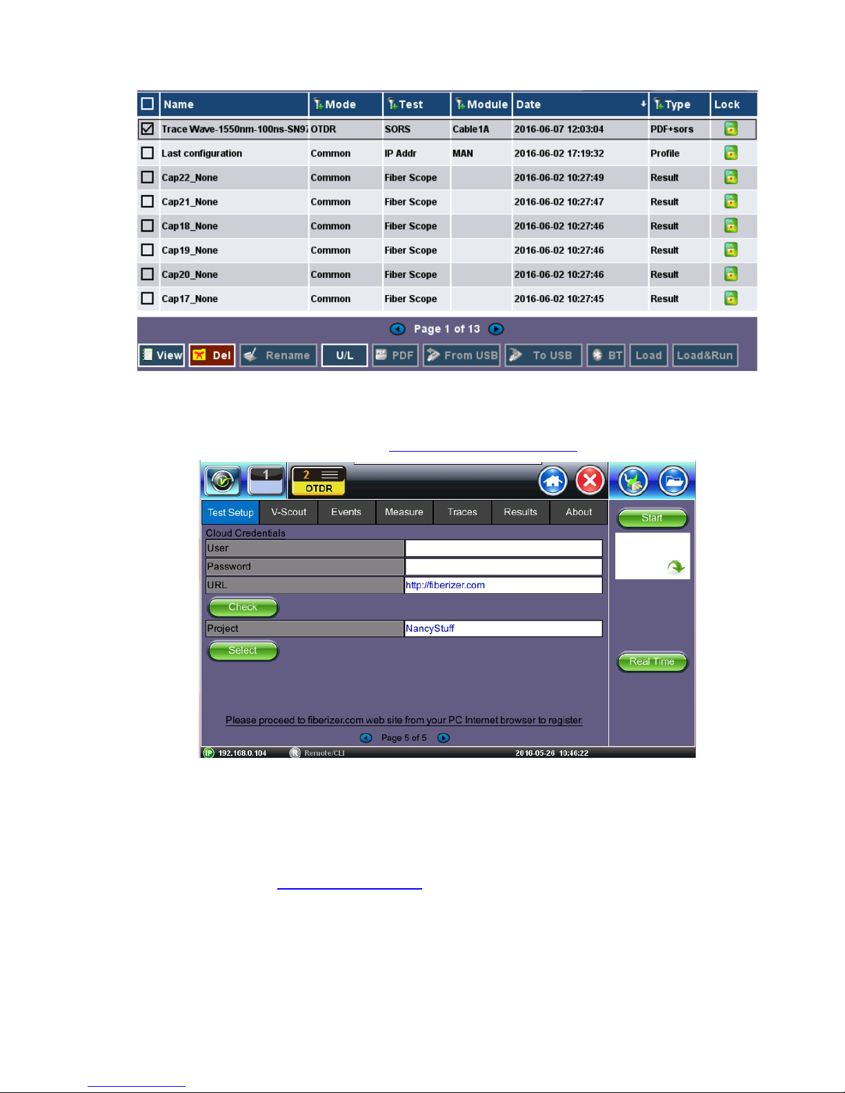
OTDR Series e-Manual, D07-00-076P-RevC00 Page 80 of 107
7.2.5 Cloud Credentials
The user can register for a Cloud account: https://cloud.fiberizer.com.
After creating a Cloud Account, the user can then login and push test results into their account
(Page 5 of Test Setup tab):
• User - Enter the email address that was used to create the Cloud account
• Password - Enter the Password that was created with the Cloud account
• URL - The default is https://fiberizer.com. Consult factory if customer wishes to use their
own account.
• Check: Select the green Check button to verify login credentials are valid
• Project - Select a specific Project folder. This will default to the folder you created at
registration. Project folders can be shared by approved team members.

OTDR Series e-Manual, D07-00-076P-RevC00 Page 81 of 107
7.3 Making Measurements
Press Start and the measurement will begin according to the test parameters entered in the
Test Setup menu.
• The elapsed time is indicated below red stop button on the right side of the display. The
stop button will revert back to a green Start button when acquisition is complete. For VScout measurements, the acquisition wavelength is also displayed.
Press Stop to terminate the measurement manually, if required.
Use the Home icon (FX150/FX300) or App key (FX300) to toggle between active test
applications (OTDR, OPM, VFL).
7.3.1 Trace Display
When a new measurement is started, only those traces will be displayed on the screen. Any
previous traces can be accessed via the Traces tab until unit is switched off. Upon completion,
the view will default initially to the selected test mode viewing screen (V-Scout, Event (Auto), or
Measure (Manual).
If multiple wavelengths are selected in the Test Setup menu, the measurement will be
performed using all selected wavelengths one after another without stopping and will be
overlaid on screen for comparison and review. V-Scout traces are overlaid and displayed
automatically.

OTDR Series e-Manual, D07-00-076P-RevC00 Page 82 of 107
7.4 Events
7.4.1 Event Table
The Events table is available in all measurement modes. Select the Events tab to display the
trace with events. The Event table displays all events found during the analysis including those
added manually by the user.
EEvveennttTTaabbllee((mmaaxxiimmiizzeedd))
• The Event table is displayed automatically when the Events tab is selected.
• The Event table can be minimized by tapping the plus symbol just above the left of
table. This optimizes the display area and allows better viewing of the OTDR trace.
• Use Up/Down arrows to navigate the event table and to display or move to the
highlighted event.
• Use the green left/right arrows to move the marker between the start and end of fiber
being tested.
• To maximize the Event table, select the cross symbol again.
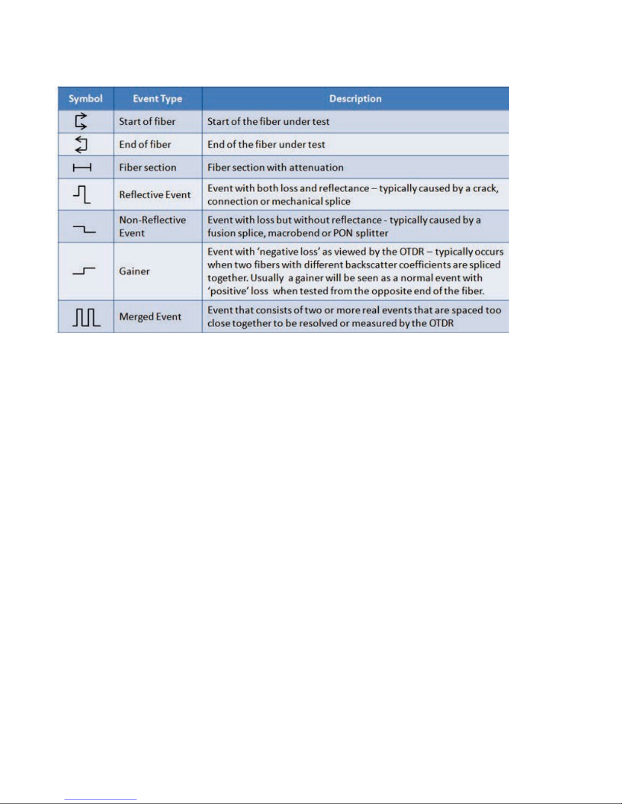
OTDR Series e-Manual, D07-00-076P-RevC00 Page 83 of 107
7.4.2 Event Types
The Event is color coded depending on Threshold settings defined in the test setup.
• Red indicates the event fails or exceeds the Pass threshold criteria.
• Green indicates the event passes the Fail threshold criteria.
7.4.3 Event Editing
Adding events:
1. Ensure the Trace view is active.
2. Position marker at the point where a new event will be inserted. You can use the Left/Right
rubber keys to position the marker more precisely, if needed.
3. Press the Add button on the right sidebar. A new event number will appear on the trace
and in the event table.
4. Select the new event in the event table and click the Modify button in the right sidebar.
Position the splice loss markers to measure the new event accurately. Once markers are
positioned, click the Accept button.
Deleting events:
1. Select the event in the Event table or by using the marker on the trace.
2. Use the left/right arrows to position the marker more accurately, if needed.
3. Once selected, press the Delete button on the right sidebar. The event will now be deleted
from the event table and the event number will no longer appear on the trace.

OTDR Series e-Manual, D07-00-076P-RevC00 Page 84 of 107
Modifying events:
1. Ensure the Trace menu is active and the Event table is shown on the screen.
2. Use the left/right arrows to highlight the necessary event in the Event Table. Press the
Modify button on the right sidebar. A marker with two small markers will appear on the
trace. When markers and measurement is performed, click the Accept button on the right
sidebar.
• Span Begin – Position marker at end of the Launch fiber and press the green Span
Begin button to set the beginning of fiber under test.
• Span End - Position marker at end of the fiber under test and press the green Span
End (if launch box is used).
• Markers - Brings marker onto the visible area of the display.
• Modify - Changes the display to allow the user to make manual adjustments to the
event table and reanalyze.
7.5 Measure Mode
There are several methods available to manually measure fiber characteristics. Prior to
performing manual measurements, it is important you become familiar with the Markers and
Zooming capabilities of the unit.
7.5.1 Markers Controls
7.5.1.1 Marker Operation
Markers are provided to measure distances accurately. Depending on measurement mode and
viewing window, one or more markers are at the User’s disposal. The Markers can be moved
using the touchscreen or using the left/right buttons on the rubber keypad (not available on
MTTplus or FX150).
The Markers display the following:
• Distance from the start of the trace to Marker “A”
• Distance from the start of the trace to Marker “B”
• Distance in between Marker “A” and Marker “B”
Note: As you move the Markers, the distance information updates automatically.
The active Marker is depicted by two small arrows pointing inwards at the base of the Marker
The Marker is divided into a thick (bottom) and thin (top) line. To move Marker A or Marker B
individually, select and drag the Marker on the thin portion of the marker. To move both
Markers together, select and drag any Marker on the thick portion of the line.
If the Markers appear off screen, use the Markers button on the right side bar to bring and
display the Markers on screen.
If a marker is moved too close to another, both will move together to ensure minimal distance
between them.
The markers can be moved separately as well as in pair (or 5 markers simultaneously in the
LSA attenuation measuring mode).

OTDR Series e-Manual, D07-00-076P-RevC00 Page 85 of 107
At the top part of the screen next to the markers, the position of the marker with respect to the
beginning of the optical fiber is indicated in kilometers, miles or feet.
In the data line at the bottom of the screen you will see the parameters of the trace
corresponding to the markers’ position and measurement mode.
7.5.1.2 Zoom/Scroll Controls
Zooming operations are possible in both Events and Measure mode.
ZZoooommOOppeerraattiioonnss
• Zoom/Scroll icon - Toggle between and enables Zoom/Scroll mode.
• Zoom mode - Magnifying glass icon appears on screen. Draw a rectangular box
over the trace with the stylus to create a zoom area. Visible part of the trace in
Preview window is marked with dotted rectangle.
• Scroll mode - Trace can only be scrolled after zooming. Hand icon appears on
screen.
User is now able to drag the trace in any direction. The mode resets to Zoom
immediately after one scroll operation has been completed.
• Zoom Out - Resets display area completely.
• Zoom Lock - Locks horizontal and vertical controls so zoom aspect is kept uniform.

OTDR Series e-Manual, D07-00-076P-RevC00 Page 86 of 107
7.5.2 Distance Measurements
DDiissttaanncceemmeeaassuurreemmeenntt––mmeeaassuurreeeexxppaannddeeddttrraacceevviieewwmmooddee
When a trace is displayed as show above, the fiber length is automatically measured from the
start of the trace (or Span Begin) to each of the two markers and in between the markers.
Proper marker placement is critical for accurate measurements. To position the marker/s
accurately, expand the trace horizontally and vertically (using the Zoom Controls) and position
the marker on event’s left edge (first rising or falling pixel).
The distance (km, miles or feet) will be indicated next to the top of the marker.
Note: The distance accuracy depends on the correctness of optical fiber refraction index value
setting.
7.5.3 Loss Measurements
Loss Modes - Several Loss modes are available for manual measurements depending on
measurement application:
• 2-Pt Loss
• 2-Pt LSA
Two Point Loss measurement
• Reflectance
• ORL (Optical Return Loss)
• Splice Loss
7.5.3.1 Two Point Loss (2-Pt Loss)
The 2-Point Loss mode uses a data point at Marker A and Marker B to calculate the dB level
difference between the two points. Usually the backscatter level value of Marker A is greater
than the level of Marker B and a positive loss measurement is displayed. If the loss value is
reported as a negative quantity, it is termed a “gainer.” Measure loss between two points using
the Loss (2-point) mode (using two markers):

OTDR Series e-Manual, D07-00-076P-RevC00 Page 87 of 107
• The data at the bottom of the screen displays: Distance between markers A-B
• Loss between markers A-B in dB
• Attenuation between markers A-B
7.5.3.2 Two Point LSA (2-Pt LSA)
To increase the accuracy of a loss or attenuation measurement, a section of the trace
preceding and following the marker A and marker B can be approximated by a straight line. In
this mode, a Least Squares Approximation technique is used to determine the best intercept
values based on the marker positions. The length of these LSA sections is user selectable.
• Select LSA from drop-down list - An approximation line will appear on the screen
between markers. The data box at the bottom displays:
• Distance between marker A and B (km, miles, feet)
• Level difference in dB
• Attenuation based loss/distance
7.5.4 Splice Loss Measurement
Determines the Splice Loss in the optical fiber connection using the five markers method.
SSpplliicceeLLoossssuussiinngg55--PPooiinnttLLSSAAmmeetthhoodd
1. Select trace for measurement (if multiple traces are displayed on screen). The trace to be
measured can be selected using the green arrow in the trace overview window.
2. Select Splice (Spl) from drop-down list.
3. Expand or zoom the trace horizontally and vertically (using Zoom Controls) and position
event in the middle of the screen using the scroll function. Always ensure that a part of the
trace is visible on either side of the event so you can place markers properly.
4. Position center marker on the event’s rising or falling edge. You can use the rubber keypad
to place the marker exactly, if needed.

OTDR Series e-Manual, D07-00-076P-RevC00 Page 88 of 107
5. Position the first two markers on a section of backscatter preceding the event and position
the last two markers on a section of backscatter after the event ensuring that enough
pre/post backscatter is used to make an accurate measurement. Markers A and B should
be placed on the left and right but as close to one another as possible. The whole transition
section should stay between them.
Note: All five markers can be moved independently or moved as a group simultaneously
depending which marker is active.
The sections between the first two markers and the last two markers are approximated by
straight lines (LSA) whilst the value of event loss is defined by the position of the center
marker.
The result box at the bottom of the screen displays:
• Spl (km, meters, miles or feet) - distance of center marker
• Loss of the event in dB based on the pre/post LSA sections and center marker
• Reflectance in dB if event is reflective
7.5.5 Reflectance Measurement
Reflectance is measured in -dB (negative decibels). A smaller negative value (-65dB) indicates
a smaller reflection whereas a larger negative value (-45dB) indicates a larger reflection.
Larger reflectance will appear as a higher spike on the trace.
1. Select trace for measurement (if multiple traces are displayed on screen). The trace to be
measured can be selected using the green arrow in the trace overview window.
2. Select Reflectance (Refl) from the drop-down list at the bottom of the display.
3. Expand the trace horizontally and vertically (using Zoom Controls) to display the reflection
correctly. The entire reflection should be displayed including a small section of the trace
preceding and following the event.
4. Place the left marker on the event’s rising edge. The right marker is placed on the peak of
the reflection.
The result box at the bottom of the screen displays:
• Distance of A cursor (reflection) from Start of test fiber
• Distance of B cursor (top of reflection) from Start of test fiber
• Distance between markers A->B
• Reflection for this even (-dB)

OTDR Series e-Manual, D07-00-076P-RevC00 Page 89 of 107
7.5.6 ORL Measurement
ORL is the total amount of light being reflected back towards the transmitter or source. This
includes all backscatter and all reflections. The OTDR can calculate ORL from the fiber trace
using the following procedure:
1. Make sure the Trace is active.
2. Select ORL from drop-down list.
3. Place the marker A at the beginning of the fiber and marker B at the end of the fiber span
under measurement.
The Result box at the bottom of the screen displays:
• Distance to A cursor
• Distance to B cursor
• Distance between markers A-B
• Loss between the markers A-B (dB)
• Optical Return loss (ORL), dB

OTDR Series e-Manual, D07-00-076P-RevC00 Page 90 of 107
7.6 Traces
Select the Traces tab to view the active or measured OTDR traces. The color-coded blocks
represent the corresponding trace viewed in the OTDR display.
The OTDR can display up to ten traces simultaneously i.e. an active trace and nine additional
traces.
To view the trace, select the necessary file using the check box. The trace will be activated
automatically and displayed on screen. Traces are displayed along with the following
parameters;
• Name - File name as saved
• Dir – AB or BA
• LMax (km) - Distance range (km) used for the test
• Tp (ns) - Pulse width used for the test
• Time (m:s) - Acquisition time used for the test

OTDR Series e-Manual, D07-00-076P-RevC00 Page 91 of 107
7.6.1 Trace Properties
The traces in the memory are saved in BELLCORE, version 2.0 format. The OTDR trace files
have the extension .sor which means Standard OTDR Record.
These OTDR trace files can be opened by the software of other OTDR vendor applications
provided the format is supported.
If the measurement was performed at several wavelengths simultaneously, the traces are
saved as a group i.e. they will share the same common name but with wavelength added (e.g.
01_meas_1310 and 01_meas_1550, etc.)
Press the Information button in the right sidebar to open the Trace Information window. The
window contains following information relating to the saved file:
• Device: OTDR supplier name, Mainframe ID and serial #, and optical module serial # (if
applicable)
TTrraacceeIInnffoorrmmaattiioonn--DDeevviicceess
• General: Date/Time, Job ID, Cable ID, Fiber ID, Group ID, Fiber Type,
Originating/Terminating locations, and Comments
• Measurement: Test parameters used to make measurement

OTDR Series e-Manual, D07-00-076P-RevC00 Page 92 of 107
TTrraacceeIInnffoorrmmaattiioonn--MMeeaassuurreemmeenntt
• Thresholds: Analysis thresholds used to analyze the trace, as well as PON
identification for LinkMap
• Cables: Span Start and Span End information
TTrraacceeIInnffoorrmmaattiioonn--CCaabblleess

OTDR Series e-Manual, D07-00-076P-RevC00 Page 93 of 107
Span Begin and Span End
Refer to section Launch/Receive fiber offset.
The user can offset the length of an external launch fiber or patchcord, which is connected to
the fiber under test; otherwise, it becomes part of the fiber span and analysis. The launch fiber
can be offset or compensated in any of the following ways:
• Entering the known distance manually in km, meters, miles or feet.
• Entering the index # based on the event table.
• Positioning the left marker at the event and pressing Span start in the right side column.
7.6.2 Saving OTDR Traces
The same procedure applies to offsetting Receiver fibers which are often used in Fiber to The
Antenna (FTTA) applications.
Note: The FX300 and RXT OTDRs have a built-in launch fiber which is 40 meters in length.
This fiber section will appear in grey color preceding the first event. This internal launch fiber
allows the user to characterize the first connector of the fiber under test and evaluate its
performance (insertion loss and reflectance). The MTTplus OTDR has an optional built-in
launch fiber.
Using any of the above methods, the launch fiber can be offset and excluded from the fiber
span measurement.
TTrraacceeIInnffoorrmmaattiioonn––CCaabblleessLLaauunncchhOOffffsseett

OTDR Series e-Manual, D07-00-076P-RevC00 Page 94 of 107
7.6.3 Saving OTDR Traces with Embedded GPS and Camera Image
7.6.3.1 Obtaining GPS Coordinates
To obtain the GPS coordinates for your current location:
1. Access Utilities>More>GPS/High Precision Clock.
2. Connect the antenna to the RF connector port (brass) located at the top of the unit.
3. Turn GPS ‘ON’ to begin searching until your GPS Status is Lock.
Note: To include GPS coordinates and camera images with OTDR files, the test set
must have the GPS option enabled, an external ‘active’ antenna connected and the
Camera option installed.
7.6.4 Adding GPS to OTDR file (optional feature)
The GPS coordinates can be added by using:
• AutoSave: Select the Ask Before Save checkbox.
• Manual Save mode: Select the GPS checkbox.

OTDR Series e-Manual, D07-00-076P-RevC00 Page 95 of 107
7.6.5 Adding Camera Image OTDR file (MTTplus only)
A Camera image can be added using the Manual Save only mode (AutoSave disabled) mode
to display the Result AutoSaving pop up window. Enter all AutoSave field entries and select
Generate PDF Report and/or select Add V-Scout Diagram.
1. Select the Add Image to pop up the camera image.
2. Select red Camera button to capture results.
or select red X button to exit Camera capture mode.
3. Click the green OK button to finalize the save process.

OTDR Series e-Manual, D07-00-076P-RevC00 Page 96 of 107

OTDR Series e-Manual, D07-00-076P-RevC00 Page 97 of 107
7.7 Results
The Results tab displays the following information pertaining to OTDR traces. To expand the
selection or folder directory, tap on the arrow. An arrow pointing to the right indicates the
branch is collapsed whereas an arrow pointing downwards indicates the branch is expanded.
The traces are saved in the following folder directory hierarchy:
• Job ID
• Cable ID
• Fiber ID
• Results – Traces
• Save: Saves file when autosave is disabled.
• Load: Displays selected trace for viewing.
• Modify: Renames or removes selected file.
• Pull: When connected, pulls file from Fiberizer Cloud onto test set.
• USB Export: Exports selected test results to USB stick using standard MyVeEX tree
directory format or a flat file when all files should be saved in a single folder.

OTDR Series e-Manual, D07-00-076P-RevC00 Page 98 of 107
7.7.1 File Management
FFiilleeLLooccaattiioonn
• Select Files/Saved menu to access saved traces or results
• Use the stylus to select a file from the list.
• Files types are as follows:
• OTDR traces are saved as SOR files
• Fiberscope images are saved as PNG files
• Optical Power Meter (OPM) results are saved as text/xml files

OTDR Series e-Manual, D07-00-076P-RevC00 Page 99 of 107
FFiilleeMMaannaaggeerr
7.7.2 Saving/Printing Traces to PDF/USB/Bluetooth
The saved OTDR sor file can be exported in several ways:
• To save to PDF:
• Use the Save as feature on Setup Page 3 and select Enable+Report (pdf) or Ena
(bled+V-Scout+Report). (User can browse and open a file with help of standard
Adobe Reader software.)
• Saving to USB - exports saved file to USB memory device if plugged in. Each file is
saved into its own folder using MyVeEX tree directory format. Use the Results View
USB Export Flat feature if you want all files to be saved in the same folder.
PPrriinnttiinngg//SSaavviinnggRReessuullttttooPPDDFF//UUSSBB//BBlluueettooootthh

OTDR Series e-Manual, D07-00-076P-RevC00 Page 100 of 107
• Export to Bluetooth - transfers OTDR sor file via Bluetooth connection to a PC or
Mobile phone.
• Tablet. Requires Bluetooth dongle accessory
Select the folder containing the test results you want to export to highlight it. Tap USB Export
and select tree (“MyVeEX”) or Flat (same folder) in which to export to USB. The files can be
found on the USB stick in the OTDR Export folder.
7.7.3 File Operations
In the File menu, you are able to delete or rename a selected result file or trace.
 Loading...