


Table of Contents
eCPRI Testing User Manual D07-00-131P RevA00
Page 2 of 53
1.0 About This User Manual
2.0 Introduction to eCPRI Testing for 10G/25G with RS-FEC
3.0 Safety Information
4.0 Basic Operations
5.0 Utilities
6.0 eCPRI
6.1 eCPRI Testing Overview
6.2 Interface Specifications
6.2.1 Protocol Stack
6.2.2 Key Features
6.2.3 Data Framing
6.2.4 One Way Latency Measurement
6.3 Setup
6.3.1 Test Port Selection
6.3.2 Port Setup
6.3.3 Measurement Settings
6.3.4 eCPRI Tests
6.4 Throughput
6.4.1 Setup
6.4.1.1 Header Settings
6.4.1.2 Traffic Settings (Per Stream Configuration)
6.4.1.3 General Throughput Settings (Global Configuration)
6.4.1.4 Error/Alarm Injection Settings (Per Stream Configuration)
6.4.1.5 Summary
6.4.1.6 Starting/Stopping a Throughput Test
6.4.2 Throughput Results
6.4.2.1 Global/Aggregate Results
6.4.2.2 Per Stream Results

6.4.3 Saving Throughput Results
eCPRI Testing User Manual D07-00-131P RevA00
Page 3 of 53
6.5 Packet Capture
6.5.1 Packet Capture Setup
6.5.2 Packet Capture Results
7.0 Warranty and Software
8.0 Product Specifications
9.0 Certification and Declarations
10.0 About VeEX
Go back to top

1.0 About This User Manual
eCPRI Testing User Manual D07-00-131P RevA00
Page 4 of 53
This user manual is suitable for novice, intermediate, and experienced users and is intended to help you successfully use the
features and capabilities of the various modules for test platforms. It is assumed that you have basic computer experience and skills,
and are familiar with IP and telecommunication concepts, terminology, and safety.
Every effort was made to ensure that the information contained in this manual is accurate. However, information is subject to change
without notice. We accept no responsibility for any errors or omissions. In case of discrepancy, the web version takes precedence
over any printed literature.
(c) Copyright 2019 VeEX Inc. All rights reserved. VeEX, VePAL, and Fiberizer are registered trademarks of VeEX Inc. and/or its
affiliates in the USA and certain other countries. All trademarks or registered trademarks are the property of their respective
companies. No part of this document may be reproduced or transmitted electronically or otherwise without written permission from
VeEX Inc.
This device uses software either developed by VeEX Inc. or licensed by VeEX Inc. from third parties. The software is confidential
and proprietary of VeEX Inc. The software is protected by copyright and contains trade secrets of VeEX Inc. or VeEX's licensors.
The purchaser of this device agrees that it has received a license solely to use the software as embedded in the device, and the
purchaser is prohibited from copying, reverse engineering, decompiling, or disassembling the software.
For more technical resources, visit the VeEX Inc. web site at
this product, call or e-mail our customer care department for customer support. Before contacting our customer care department,
have the product model, serial number, and software version ready. Please locate the serial number on the back of the chassis.
Please provide this number when contacting VeEX customer service.
Customer Care:
Phone: + 1 510 651 0500
E-mail:
Website: www.veexinc.com
Go back to top Go back to TOC
customercare@veexinc.com
www.veexinc.com. For assistance or questions related to the use of

2.0 eCPRI Testing for 10G/25G/25G with RS-FEC
eCPRI Testing User Manual D07-00-131P RevA00
Page 5 of 53
eCPRI is designed to comply with the more stringent requirements brought on by 5G standards for fronthaul solutions based on
CPRI/OBSAI. These include:
Increase bandwidth
Bandwidth scalability and flexibility
Low latency
Flexibility in functional split options between Remote Unit (RU) and Centralized Unit (CU)
Note: eCPRI testing availability depends on the test platform and module. Options and features described in this manual may not be
available on all software versions and platforms. Refer to the latest specification sheet on
available test modes for each platform and module.
Test Interfaces for eCPRI
10G
25G
25G with RS-FEC Support
Framed Traffic
Layer 2 or Layer 4 traffic
Test Frame Header: Protocol Rev. 1, Configurable C field, Configurable message
www.veexinc.com for a breakdown of
Packet Capture and Decode
Line rate packet capture
Full frame capture or truncated
Layer 2, Layer 4, Message Type
Go back to top Go back to TOC

3.0 Safety Information
eCPRI Testing User Manual D07-00-131P RevA00
Page 6 of 53
Safety precautions should be observed during all phases of operation of this instrument. The instrument has been designed to
ensure safe operation however please observe all safety markings and instructions. Do not operate the instrument in the presence
of flammable gases or fumes or any other combustible environment. VeEX Inc. assumes no liability for the customer's failure to
comply with safety precautions and requirements.
Optical Connectors
The test sets display a laser warning icon when the laser source is active to alert the user about a potentially dangerous situation. It
is recommended to:
1. Deactivate the laser before connecting or disconnecting optical cables or patchcords.
2. Never look directly into an optical patchcord or an optical connector interface (SFP+) while the laser is enabled. Even though
optical transceivers are typically fitted with Class 1 lasers, which are considered eye safe, optical radiation for an extended
period can cause irreparable damage to the eyes.
3. Never use a fiber microscope to check the optical connectors when the laser source is active.
Safe Module Handling
While replacing test modules, all work on the open panel must be performed only by suitably qualified personnel who is familiar with
the dangers both to people and to the instrument itself.
Modules are not hot swappable. The platform must be turned off and unplugged from VAC mains when removing or inserting
test modules.
For safety and EMC (Electromagnetic Compatibility), empty module slots must be properly covered with blank panel covers.
Prevent foreign objects from entering the unit, before, during and after module exchange or re-configuration process. They
could create short circuits or damage internal fans.
Always store test modules by themselves in individual ESD protected packaging (with no loose elements, like screws or
tools).
Lithium-ion Battery Precautions
Lithium-ion (Li-ion) battery packs are compact and offer high capacity and autonomy, which make them ideal for demanding
applications, like providing long lasting power to portable test equipment. For safety reasons, due to their high energy concentration,
these batteries packs and products containing them must be used, charged, handled, and stored properly, according to the
manufacturer’s recommendations.
Li-ion battery packs contain individual Li-ion cells as well as battery monitoring and protection circuitry, sealed in its plastic container
that shall not be disassembled or serviced.
The test set unit's battery pack is also fitted with a safety connector to prevent accidental short circuits and reverse polarity.
Always charge the unit's battery pack inside the test platform battery bay using the AC/DC adapter supplied by VeEX.
Do not charge or use the battery pack if any mechanical damage is suspected (shock, impact, puncture, crack, etc).
Do not continue charging the battery if it does not recharge within the expected charging time
Storage: For long term storage, the battery pack should be stored at 20°C/68°F (room temperature), charged to about 30 to
50% of its capacity. Spare battery packs should be charged and used at least once a year to prevent over-discharge (rotate
them regularly).
It is recommended to charge and use battery packs at least every three months. Battery packs shall not go without recharging
(reconditioning) for more than six months.
After extended storage, battery packs may reach a deep discharge state or enter into sleep mode. For safety reasons, Li-ion

batteries in deep discharge state may limit the initial charging current (pre-recharge) before starting their regular fast charging
cycle. The pre-charging state may take several hours.
eCPRI Testing User Manual D07-00-131P RevA00
Page 7 of 53
Air transportation of Li-ion batteries is regulated by United Nations' International Air Transportation Association (IATA)
Dangerous Goods Regulations and by country-specific regulations. Please check local regulations and with common carriers
before shipping Li-ion battery packs or products containing relatively large Li-ion battery packs.
Electrical Connectors
Telephone lines may carry dangerous voltages. Always connect the electrical test ports to known test interfaces which carry low
level signals.
ESD: Electrostatic Discharge Sensitive Equipment
Test modules could be affected by electrostatic discharge. To minimize the risk of damage
when replacing or handling test modules, make sure to follow proper ESD procedures and
dissipate any electrostatic charge from your body and tools and the use proper grounding gear.
Perform all work at a workplace that is protected against electrostatic build-up and
discharging.
Never touch any exposed contacts, printed circuit boards or electronic components.
Always store test modules in ESD protected packaging.
Wear ESD protection and grounding gear when:
Inserting, extracting, or handling test modules.
Inserting or removing SFPs, XFPs, QSFPs, or CFPs from the platform.
Connecting or disconnecting cables from modules or platform.
Go back to top Go back to TOC

4.0 Basic Operations
eCPRI Testing User Manual D07-00-131P RevA00
Page 8 of 53
For more information about Basic Operations, Home menu, Launching Test Applications etc., see the test unit's Platform User
Manual on
Go back to top Go back to TOC
www.veexinc.com.

5.0 Utilities
eCPRI Testing User Manual D07-00-131P RevA00
Page 9 of 53
For more information on Utilities and Tools available, see the test unit's Platform User Manual on www.veexinc.com.
Go back to top Go back to TOC
6.0 eCPRI
eCPRI Testing User Manual D07-00-131P RevA00
Page 10 of 53
6.1 eCPRI Testing Overview
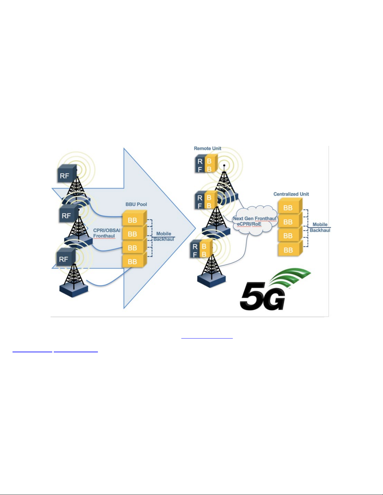
The Common Public Radio Interface (CPRI) forum introduced a new more stringent Ethernet packet based fronthaul interface,
eCPRI, due to limitations for 5G deployments based on traditional CPRI or OBSAI.
To ensure that 5G network's strict requirements are met in the fronthaul, the eCPRI Transport Network requirement document
establishes classes of service for data and C&M traffic. With full line rate eCPRI traffic generation capabilities and high accuracy
one-way latency measurements, the eCPRI test application provides the tools necessary to ensure that the eCPRI transport network
is ready for 5G deployments.
CPRI Mobile Fronthaul Evolution
This protocol has been developed by Ericsson AB, Huawei Technologies Co. Ltd, NEC Corporation, Alcatel Lucent and Nokia
Siemens. The standard is public and can be downloaded from
Go back to top Go back to TOC
http://www.cpri.info.
6.2 Interface Specifications
eCPRI Testing User Manual D07-00-131P RevA00
Page 11 of 53
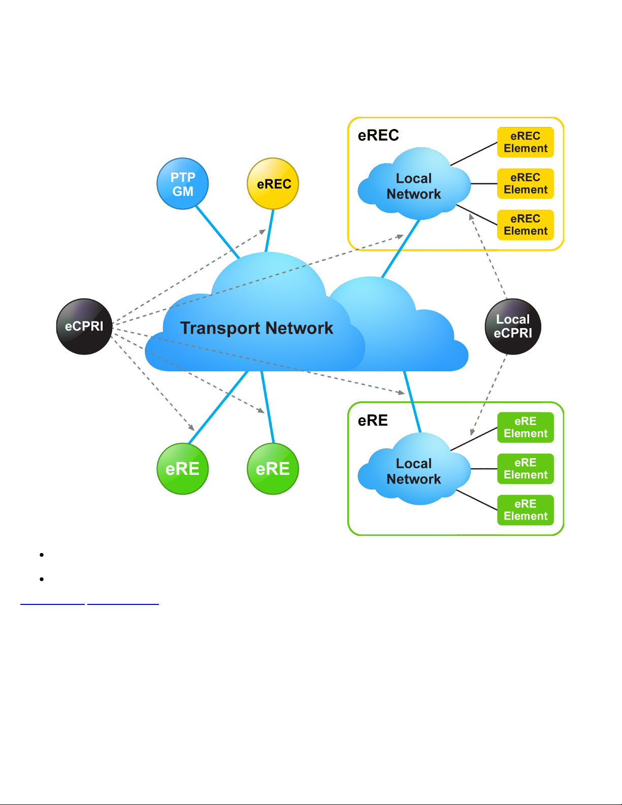
eCPRI System Architecture Example*
(*eCPRI Interface Specifications ver 1.1)
CPRI Specification was written with the goal to be generic enough to support scalable rates, physical access medium type,
and air interface technologies.
eCPRI relies on existing standards for Ethernet/IP networking, synchronization, and security.
Go back to top Go back to TOC
6.2.1 Protocol Stack
eCPRI Testing User Manual D07-00-131P RevA00
Page 12 of 53
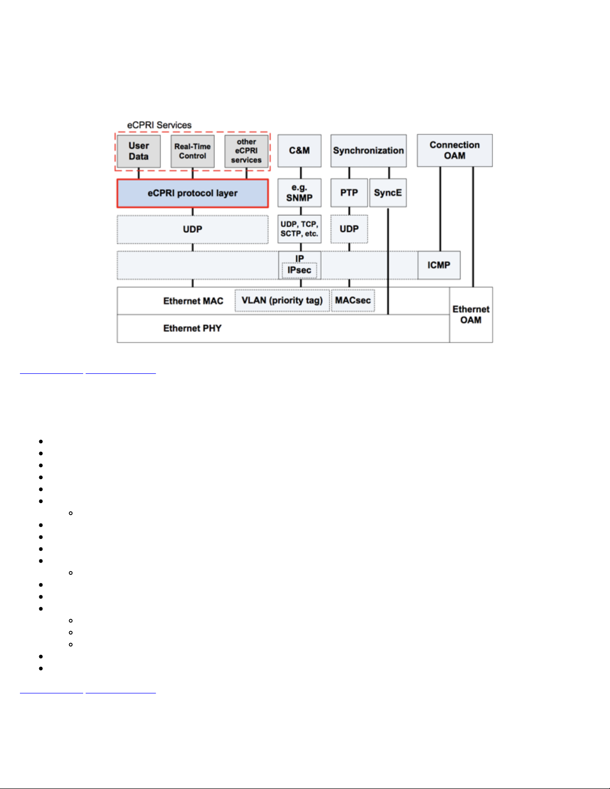
eCPRI Protocol Stack*
(*eCPRI Interface Specifications ver 1.2)
Go back to top Go back to TOC
6.2.2 eCPRI Key Features
Key features of eCPRI include:
25G/10G eCPRI (Protocol ver.1)
Ethernet Type: AE-FE (eCPRI)
Configurable C field and message type
Dual-port testing capabilities
RS-FEC support
Multi-stream testing up to 32 independent streams
Each stream can be set with independent frame size, bandwidth, traffic profile, and QoS levels
Throughput testing at Layer 2 and Layer 4
Frame sizes from 64 to 1518 bytes and jumbo frames up to 16000 bytes (Layer 2 only)
Configurable Source and Destination MAC
Fully configurable IPv4 or IPv6 header
UDP Header configurable Source and Destination ports
Q in Q (VLAN stacking up to 3 VLAN tags with configurable priority and type)
MPLS up to 3 labels with configurable Label/S/CoS and TTL
Test Patterns:
PRBS pattern: 231-1, 223-1, 215-1, 211-1
PRBS normal and inverted patterns
All 0s, All 1s, and User Defined
High accuracy One-Way-Delay latency measurement
Line rate packet capture
Go back to top Go back to TOC
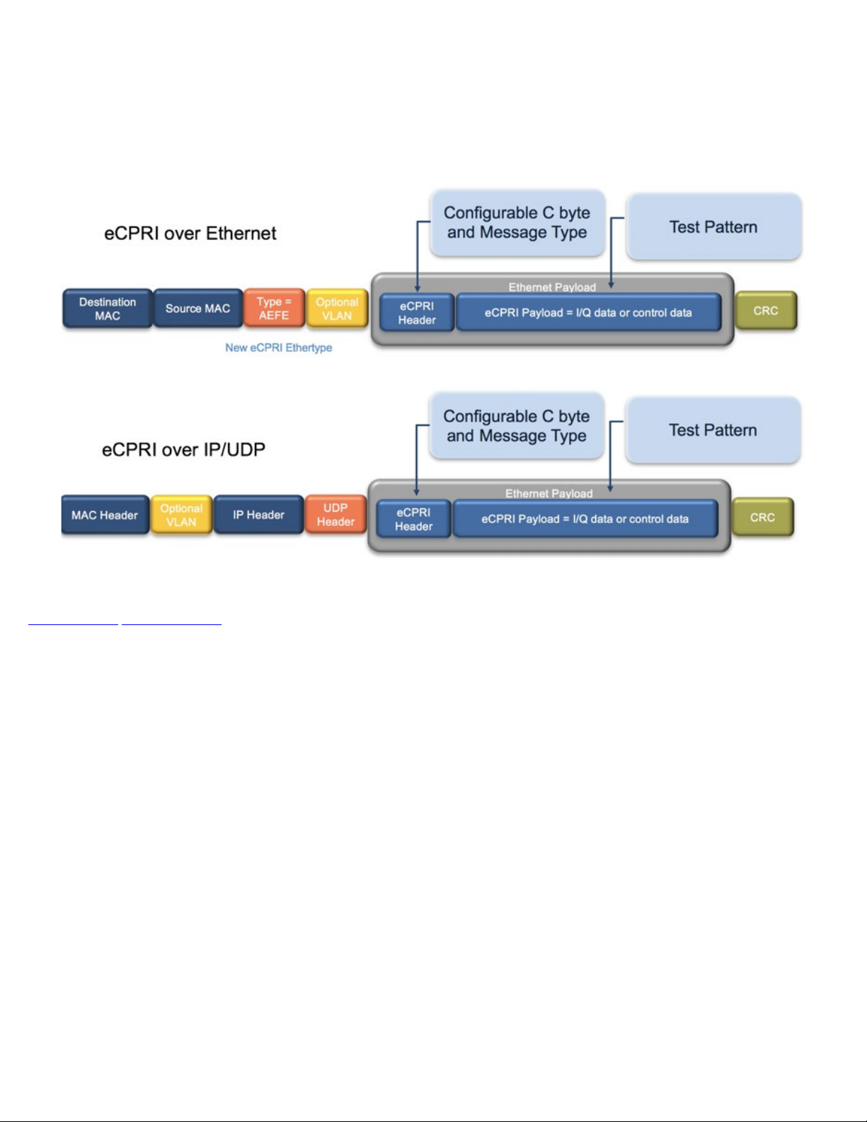
6.2.3 eCPRI Data Framing
eCPRI Testing User Manual D07-00-131P RevA00
Page 13 of 53
eCPRI Data Framing
Go back to top Go back to TOC
eCPRI Testing User Manual D07-00-131P RevA00
Page 14 of 53
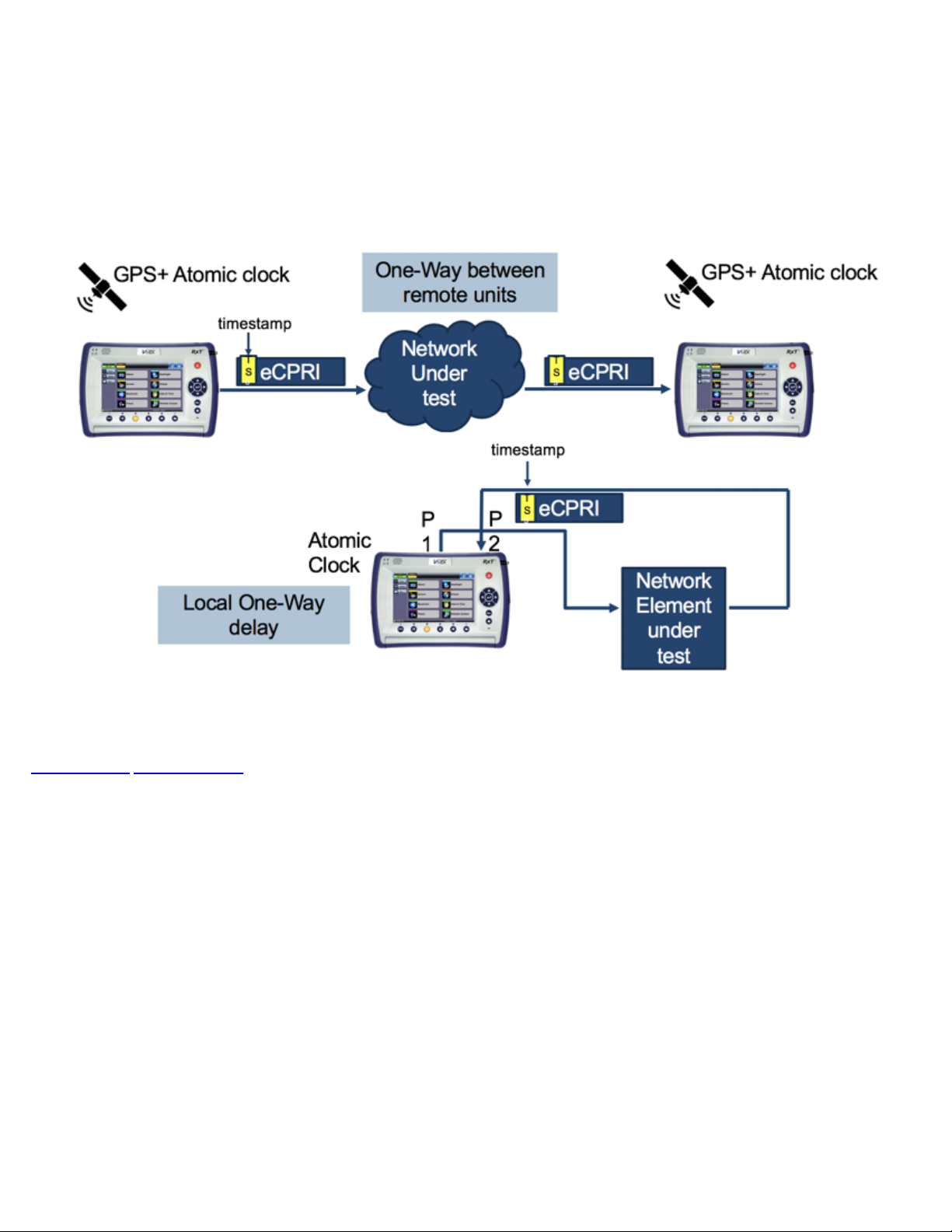
6.2.4 eCPRI One Way Latency Measurement
The diagram below shows how eCPRI works with RXT-6000e and RXT-6200 test modules.
eCPRI One Way Latency Measurement
Go back to top Go back to TOC
6.3 eCPRI Setup
eCPRI Testing User Manual D07-00-131P RevA00
Page 15 of 53
Test mode, test port(s), and network settings are required prior to performing any measurements or applications.
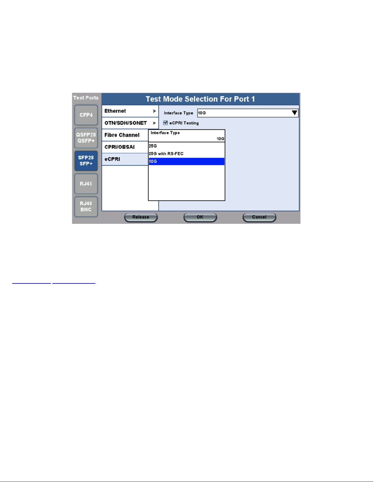
6.3.1 Test Port Selection
Test Mode Selection
This menu is accessed via the Test Port button located at the top left hand side of the screen.
To select the eCPRI test:
1. Click the SFP28/SFP+ Test Port, and then select the eCPRI test mode.
2. Select the test interface type (10G, 25G, or 25G with RS-FEC), and then click OK.
Go back to top Go back to TOC
6.3.2 Port Setup
Configure the Test Ports and/or Test Interfaces using the Setup menu on the Home page. The available configuration settings
depend on the interface selected.
Select the operation mode and the interfaces that will be used to carry out tests. Once the operating mode and interfaces are
selected, the the auto-negotiation, speed, duplex, and flow control settings for each port (where applicable) can be configured.
The figure below shows a 10G Port Setup.
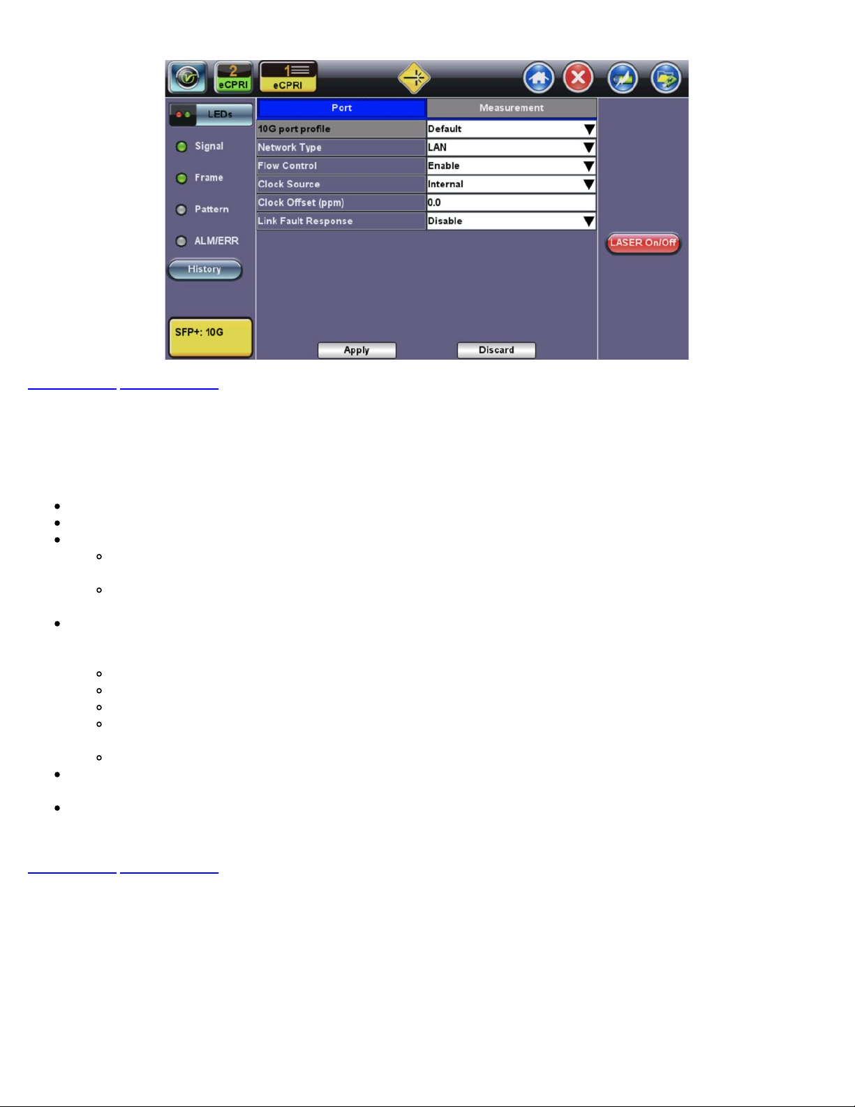
10G Fiber Port Setup
Go back to top Go back to TOC
eCPRI Testing User Manual D07-00-131P RevA00
Page 16 of 53
Port Setup
Port Profile: Lock, Delete, Save, Save as..., Default, Last configuration
Network Type: LAN
Flow Control: Enable/Disable
When flow control is enabled, the test set will respond to pause frames received by the link partner by adjusting the
transmit rate.
When flow control is disabled, the test set ignores all incoming pause frames from the link partner and continues
transmitting at the configured transmit rate.
Clock Source:
Note: For one-way delay measurements between remote test units, the clock source should be set to 1PPS external, GPS
1PPS or Atomic 1PPS.
Internal: The internal clock has an accuracy of +/- 3.5ppm conforming to G.812 recommendations.
External: 2Mbps, 2MHz, 1.5Mbps, 1.5MHz, 10MHz, 1PPS
RxCLK: The clock is derived from the received signal and the jitter of the incoming signal is suppressed.
GPS 1PPS: The optional built-in GPS provides a (raw) 1PPS timing signal (clock) and is aligned to the standard
second.
Atomic 1PPS: The optional built-in Atomic Clock provides a stable 1PPS timing signal.
Clock Offset (ppm): The clock for the transmitter is derived from the internal clock generator.
Frequency offset: +/- 150 ppm with 0.1 ppm resolution.
Link Fault Response: Enable/Disable
Go back to top Go back to TOC

6.3.3 Measurement Settings
eCPRI Testing User Manual D07-00-131P RevA00
Page 17 of 53
10G Measurement Setup
The measurement and event log settings are configured in this screen.
Profile: Last configuration, Delete, Save, Save as..., Default.
Mode: Manual, timed, or auto mode are available.
Manual mode: Starts and stops the measurements manually.
Timed mode: Defines the duration of the test; after the test is started, the test will run for the configured duration and
stop automatically.
TX Start: Separated or Coupled. Configure how the measurements are started by separating or coupling the transmitter and
receiver.
Separated: Independent control (Start/Stop) of the transmitter is enabled. At the start of the test only the receiver is
turned on; the transmitter must be turned on manually.
Coupled: Transmitter and receiver are turned on at the same time, and the measurements start at the same time at
the start of the test.
Results Auto Save: ON/OFF. When ON is selected, results are saved automatically.
Maximum Number of Saved Events: 128, 256, 512, 1024. Maximum number of error and alarm events recorded during a
test.
Go back to top Go back to TOC

6.3.4 eCPRI Tests
eCPRI Testing User Manual D07-00-131P RevA00
Page 18 of 53
After setting up test ports and configuring the measurements, tests are available from the Throughput and Packet Capture options
on the Home page.
Note: Actual screens my differ depending on the installed module.
eCPRI Home page
Go back to top Go back to TOC

6.4 Throughput Testing
eCPRI Testing User Manual D07-00-131P RevA00
Page 19 of 53
6.4.1 Setup
To access Throughput testing features, tap Throughput from the Home menu.
Overview:
This application is very useful in verifying the transport of traffic with different prioritization settings across a network link. The test
helps verify that the network can handle high priority traffic and low priority traffic accordingly.
The Throughput application performs the following measurements:
Throughput performance
Frame Loss analysis
Delay analysis
Frame/Packet arrival analysis
Received Traffic Type analysis
Received Traffic Frame Size analysis.
On the transmit side, the Throughput application currently allows up to 32 streams with its MAC and IP address, VLAN tags (up to
3), bandwidth/rate, frame size, and L2 and/or L4 quality of service (QoS) parameters. On the receiver end, the traffic is analyzed on
a per stream basis as well as a global or aggregate measurement.
eCPRI Throughput testing at Layer 2 and 4 is supported. Throughput can be configured to use either stress patterns or user defined
test patterns to simulate various conditions. The test layer, frame header, traffic profile, error injection, and control settings of the farend device (if applicable) must be configured prior to testing.
Go back to top Go back to TOC
6.4.1.1 Frame Header Settings
The following parameters must be configured prior to performing a Throughput test:
Layer 2:
Test pattern is encapsulated into a valid Ethernet frame with SOF, Preamble, and CRC field
A default or user configured Media Access Control (MAC) address is added to the frame
Layer 4:
A default or user configured Media Access Control (MAC) address is added to the frame.
A default or user configured IP address is added to the frame.

eCPRI Testing User Manual D07-00-131P RevA00
Page 20 of 53
Header Settings
Throughput Header Settings: Layer 2
Throughput Header Settings: Layer 4
Profile: Load a previously configured test profile or create a new profile from existing settings.
Stream #: Number of stream for which to configure the profile. Use the Prev and Next buttons to change streams.
Note: Use the General tab to configure the total number of streams. See
for more details.
Test Layer: Select layer to perform the test. Layer 2 or 4.
Frame Type: (Layer 2 only) Ethernet II (DIX); named after DEC, Intel, and Xerox, this is the most common frame type today.
VLAN: Off, 1 tag, 2 tags, 3 tags (VLAN stacking is an option for Q-in-Q applications)
MPLS (Layer 4 only): Off, 1 tag, 2 tags, 3 tags
Protocol (Layer 4 only): UDP
eCPRI, DATA, and CRC are selected automatically for Layers 2 and 4. IP is selected automatically for Layer 4 only.
General Throughput Settings (Global Configuration)

The most common Ethernet Frame format, Type II
eCPRI Testing User Manual D07-00-131P RevA00
Page 21 of 53
Go back to top Go back to TOC
MAC, VLAN, MPLS, IP, UDP, eCPRI, DATA, and RX Filter Test Pattern Configurations:
To configure the MAC addresses, IP addresses, VLAN tag(s), and test pattern, tap on the frame image displayed on the screen.
This brings up the configuration screens for all the header fields.
Tap the Apply
streams.
MAC Header Tab:
button at the bottom to save your selections to the current stream or Apply to All to save your selections to all
MAC Source: Use the default source address of the test set or configure a new or different address.
Tap the Mac Source button at the bottom to populate the fields with default test port settings.
For Layer 4 (IPv6) only: Tap the NDP Gateway and NDP buttons at the bottom to locate MAC addresses on the local
network for the network address designated in the gateway.
MAC Destination: Configure the destination MAC address of the far-end partner test set.
Ethernet Type:
Layer 2: AE-FE (fixed)
Layer 4: Set to 0800-IP (fixed), or
select 8847-MPLS unicast or 8848-MPLS multicast if MPLS tagging is enabled.
Throughput Setup - MAC Layer 4
Go back to top Go back to TOC

eCPRI Testing User Manual D07-00-131P RevA00
Page 22 of 53
VLAN Tab:
VLAN ID: Configurable in the range 1 to 4094.
VLAN Priority: Configurable in the range 0 to 6
Type: The following selections are possible:
Drop Eligible: If enabled, a drop eligibility flag will be set.
Identifies the VLAN; used by standard 802.1Q.
It has 12 bits which allows the identification of 4096 (2^12) VLANs.
Of the 4096 possible VIDs, a VID of 0 is used to identify priority frames and value 4095 (FFF) is reserved.
Maximum possible VLAN configurations are therefore set to 4094.
Set by the Priority Code Point (PCP), a 3-bit field referring to the IEEE 802.1p priority.
Indicates the frame priority level from 0 (lowest) to 7 (highest); used to prioritize different classes of traffic
(voice, video, data, etc.).
8100 (IEEE 802.1Q tagged frame)
88a8 (IEEE 802.1ad Provider Bridging)
User Defined
IEEE 802.1Q VLAN Tag in an Ethernet Frame
Go back to top Go back to TOC
Throughput Setup - VLAN Tag configuration (Layer 4)

MPLS Tab (Layer 4 only):
eCPRI Testing User Manual D07-00-131P RevA00
Page 23 of 53
MPLS label: Configurable in the range 16 through 1,048,575 (labels 0 to 15 are reserved).
Note: Composed of 20 bits which allows for the creation of over one million labels.
CoS: Configurable in the range 0 to 6.
Note: This field is three bits in length and maps directly to IP Precedence TOS bits to provide Class of Service (COS).
S-bit: Configurable 0 or 1.
Note: The S field is one bit in length and is used for stacking labels. This is important as it is used to indicate the last
label in the label stack.
TTL: Configurable in the range 0 to 255. The default setting is 128 hops.
Note: Used to decrement the time-to-live counter.
Throughput Setup - MPLS configuration (Layer 4)
Go back to top Go back to TOC
IP Tab: Configures the destination IP address, source address and header fields.
IPv4
IP Type: IPv4, IPv6
Source and Destination IP Address: The source address is fixed to the IP address from the IP setup menu.
Subnet: Subnet mask
Gateway: Address of the network gateway
IP TOS (for Quality of Service testing): Legacy TOS or DSCP
Legacy TOS : The first three bits of the IP TOS field can be edited:
DSCP (Differentiated Services Code Point): The first six bits of the IP TOS can be edited to provide
Precedence:
000 - Routine
001 - Priority
010 - Immediate
011 - Flash
100 - Flash Override
101 - Critical
110 - Internetwork Control
111 - Network Control
TOS Values:
1000 - Minimize Delay
0100 - Maximize Throughput
0010 - Maximize Reliability
001 - Minimize Monetary Cost
0000 - Normal Service

more granular service classification.
Time To Live (TTL): Configurable in the range 0 to 255. Indicates how many hops have been traversed.
eCPRI Testing User Manual D07-00-131P RevA00
Page 24 of 53
It will be decremented by 1 each time it crosses a hop.
Do Not Fragment Flag: Fragment offset byte configurable in the range 0 to 65.528.
Note: The fragment offset field, measured in units of eight-byte blocks, is 13 bits long and specifies the
offset of a particular fragment relative to the beginning of the original unfragmented IP datagram.
Protocol: UDP (0x11), TCP (0x06), User Defined.
Throughput Setup - IP Address Settings Layer 4 (IPv4 Legacy TOS)
IPv6
IP Type: IPv6
Source and Destination IP Address: 128-bit fields. The source address is fixed to the IP address from the IP
setup menu.
Traffic Class: 8-bit level used to designate priority handling of packets.
Flow Label: 20-bit label used to identify packets for special handling.
Next Header: 8-bit field to identify the type of header that immediately follows.
Hop Limit: 8-bit field to designate the maximum number of hops from source to destination. Packet is
discarded once number is decremented to zero.
Throughput Setup - IP Address Settings Layer 4 (IPv6)

Multiple Streams - MAC/IP Address Setup
eCPRI Testing User Manual D07-00-131P RevA00
Page 25 of 53
If all of the streams are going to the same far-end unit, then the MAC/IP destination addresses must
be the same on all of the streams.
If any of the traffic streams are going to more than one far-end unit then ensure the correct MAC/IP
destination addresses are configured for the respective streams.
Go back to top Go back to TOC
UDP Header Tab:
Source Port: 16-bit fields used to identify the transmitter's and receiver's ports. Field has limit of 65,535.
Throughput Setup - UDP Settings Layer 4
Go back to top Go back to TOC

eCPRI Testing User Manual D07-00-131P RevA00
Page 26 of 53
eCPRI Header Tab:
Protocol Rev.: eCPRI Interface Specification version used (version 1 is default).
C:
0 = indicates last message
1 = indicates another eCPRI message follows
Message Type: The following types of messages are allowable in eCPRI specifications ver. 1. The default is set to 5
for One-way latency measurements.
0 = IQ Data
1 = Bit Sequence
2 = Real-Time Control Data
3 = Generic Data Transfer
4 = Remote Memory Access
5 = One-way Delay Measurement
6 = Remote Reset
7 = Event Indication
8 - 63 = Reserved
64 - 255 = Custom
Throughput Setup - eCPRI Settings Layer 4
Go back to top Go back to TOC
Data Tab: Select a test pattern that will be encapsulated in the Ethernet frame payload (for framed mode).
For both Layer 2 and 4 the following pattern is available:
PRBS:
2E31 -1 (147 483 647-bit pattern used for special measurement tasks, [e.g., delay measurements at higher bit
rates])
2^23 -1 (8 388 607 bit pattern primarily intended for error and jitter measurements at bit rates of 34 368 and
139 264 kbps)
2^15 -1 (32 767 bit pattern primarily intended for error and jitter measurements at bit rates of 1544, 2048, 6312,
8448, 32 064 and 44 736 kbps)
All 0's: Set to all zeros
All 1's: Set to all ones
User Defined: 2 bit field
Invert: Normal or inverted
Rx Live: Select checkbox to check that receiver is active and ready to receive data.

Go back to top Go back to TOC
eCPRI Testing User Manual D07-00-131P RevA00
Page 27 of 53
RX Filter Tab: Filters incoming streams. When checked, the incoming traffic flows that do not match these criterion will not
be considered for test results.
MAC Destination
MAC Source
VLAN
Ethernet Type
DSCP (Layer 4 only)
Protocol Type (Layer 4 only)
IP Destination (Layer 4 only)
IP Source (Layer 4 only)
Destination Port (Layer 4 only)
Source Port (Layer 4 only)
VLAN Eligible (Layer 4 only)
Throughput Setup - DATA Settings Layer 4
Throughput Setup - RX Filter Header Setup Settings Layer 4
Go back to top Go back to TOC

eCPRI Testing User Manual D07-00-131P RevA00
Page 28 of 53
6.4.1.2 Traffic Settings (Per Stream Configuration)
Use the Traffic tab to configure the traffic profile per stream, including frame size selection, traffic type, and transmit rate.
Stream #: Select a stream number to configure.
Traffic Flow:
Multiple Streams: Constant
Single Stream: Constant, Ramp, Burst, or Single Burst
Frame Size (Type): Fixed
Frame Size (bytes): If a fixed frame size is chosen, this option is enabled to enter the frame size. Frame sizes can be from
64 bytes to 1518 bytes, in addition to jumbo frames up to 9k bytes.
Constant Bandwidth: Configure the transmit rate for the stream. The parameters depend on the Traffic Flow selected.
Constant Traffic Flow: Constant Bandwidth
Ramp: Start BW, Stop BW, Step BW, Ramp Time, Repetitions
Burst: Burst 1 Bandwidth, Burst 1 Time, Burst 2 Bandwidth, Burst 2 Times
Single Burst: Single Burst Bandwidth
Note: The bandwidth allocation per stream is already configured in the General Settings tab, but can be modified in this screen as
well.
Throughput Traffic Settings

6.4.1.3 General Throughput Settings (Global Configuration)
eCPRI Testing User Manual D07-00-131P RevA00
Page 29 of 53
# of Streams: Up to 32 streams.
Stream #: Allocated Bandwidth per Stream: The total bandwidth for all streams cannot exceed 100%.
Total (%): Sum of all stream rates in %.
Throughput General Setup
Page 2 features One Way Delay measurement and Service Disruption Test (SDT) measurement settings.
Delay Measurement Mode: Enable/disable the round trip delay measurement. It should only be enabled when running the
test to a remote loopback.
RTD Unit Auto Scale: ON/OFF
Histogram: Enable / Disable
Sampling Period: 1sec, 10secs, 30secs, 1min, 10min, 30min, 1hr. Defines how often the RTD (round trip delay)
measurement is evaluated against the RTD threshold.
Threshold (Max RTD allowed): Input the value in us, ms or sec. Defines the maximum allowed round trip delay value. If the
RTD value exceeds the threshold, an event is logged with corresponding time stamp.
Save Histogram: Enable/Disable
SDT Measurement: Enable/Disable. The Service Disruption Test is triggered based on user established thresholds.
SDT Violation Threshold (us):Triggers an SDT Violation event in the event log. This is helpful for historical purposes
during any given test. If the measured SDT is equivalent or greater than the configured threshold an SDT Violation
event is counted.
SDT Measurement Trigger (>us): Any inter-frame gap that is equivalent or greater than the configured threshold will
trigger the SDT measurement. This is useful if a known threshold is expected from a given network under test. For
example, if the known switchover time is 50ms, the trigger can be set to a value slightly below 50ms to assure that the
SDT is measured.

Throughput General Setup - One Way Delay Service
eCPRI Testing User Manual D07-00-131P RevA00
Page 30 of 53
Multiple Streams
All streams are configured for the same test layer - if Layer 2 is selected, all streams will be Layer 2
traffic.
Go back to top Go back to TOC
6.4.1.4 Error/Alarm Injection Settings (Per Stream Configuration)
Error injection and Alarm Injection can be performed during testing by tapping the Setup Injection button. The type of errors and
error injection are configured in the Error Injection tab. Once the test is running, error injection can be performed by pressing the
Error Inject button on the right side of the screen.
Error Injection Settings
Layer: ETHERNET
Type: Type of error: CRC, TCP/UDP Checksum, Pause, OOS, Missing Sequence, or Dup. Sequence.
When Pause is selected, the unit will transmit a pause frame when the Error Inj.
button is pressed.
Behavior: How the errors will be injected: Single, Single Burst, or Rate.
Pause Quanta: Field appears when Type is set to Pause. The Pause time duration is configurable in units of 512 bit time. At
Gigabit Ethernet speed, this is equivalent to 512 ns. For example, if pause time is set to 1000, the pause duration will be set
to 1000x512 ns.
Error Count: Field appears when Behavior is set to Single Burst.
Error Rate: Field appears when Behavior is set to Rate.
Stream #: The stream to configure.
Alarm Injection Settings
Layer: ETHERNET
Type: Type of alarm: Local Fault, Remote Fault, or Optical LOS.
Alarm Inj.
Button is pressed.
Behavior: How the alarms will be injected: Continuous or Single Burst
Optical LOS Lane Selection: Checkbox appears when Type is set to Optical LOS.

Go back to top Go back to TOC
eCPRI Testing User Manual D07-00-131P RevA00
Page 31 of 53
Throughput Error/Alarm Injection Setup
6.4.1.5 Summary
The summary screen lists the MAC source, MAC destination and VLAN information of each stream. Tap the appropriate box of each
tab to reconfigure the source, destination, or VLAN information.
Throughput Summary MAC List - Level 4

Throughput Summary IP List - Level 4
eCPRI Testing User Manual D07-00-131P RevA00
Page 32 of 53
Throughput Summary VLAN List - Level 4
Throughput Summary MPLS List - Level 4

Throughput Summary Gateway List - Level 4
eCPRI Testing User Manual D07-00-131P RevA00
Page 33 of 53
Go back to top Go back to TOC
6.4.1.6 Starting/Stopping a Throughput (Multiple Streams) Test
Once all configurations have been made, tap the Start button on the right section of the screen to start the measurements.
Note: If testing on the fiber ports, make sure the LASER is turned On before starting the test.
End-to-End Testing
Connect the test set to another unit that supports eCPRI testing.
After configuring test settings on both units, start the tests.
Go back to top Go back to TOC
6.4.2 Throughput Results
When the test is first started, the screen changes to the Global/Aggregate results screen automatically.
Go back to top Go back to TOC
6.4.2.1 Global/Aggregate Results
The Global results pages display measurements for all traffic streams as well as non test traffic.
The Global Stream Summary screen displays:
Stream number (#)
Transmit and Receiver rate (bps)
Events (errors/alarms) associated with the stream

Go back to top Go back to TOC
eCPRI Testing User Manual D07-00-131P RevA00
Page 34 of 53
Throughput Results - Global Stream Summary
The Aggregate screen displays these parameters:
Line Rate (bps): This value is always fixed since it depends on the maximum capacity of the link under test, hence the test
interface that is configured.
Utilization: % of Line Rate. For example, if we transmit 100Mbps on a 1Gbps interface then the utilization value is 10% (or
100Mbps) of the total link capacity (or Line Rate).
Utilization (bps)
Framed Rate: (Payload + MAC/IP Header + VLAN Tag + Type/Length + CRC) / (Payload + Total Overhead) * Line Rate %
(in Mbps).
Data Rate: Payload / (Payload + Total Overhead) * Line Rate %.
Total # of frames, bad frames, and pause frames.
Throughput Results - Global Aggregate
Go back to top Go back to TOC

The Global Signal screen (fiber ports only) displays the optical level measured by the CFP2 or QSFP+ transceiver.
eCPRI Testing User Manual D07-00-131P RevA00
Page 35 of 53
Throughput Results - Global Signal Page 1
Throughput Results - Global Signal Page 2

Throughput Results - Global Signal Page 3
eCPRI Testing User Manual D07-00-131P RevA00
Page 36 of 53
Throughput Results - Global Signal Page 4
Go back to top Go back to TOC
The Global Errors screen displays the Current and Total error count of all streams:
Sync Header Error
Block Type Error
FCS/CRC: Number of received frames with an invalid Frame Check Sequence (FCS)
IP Checksum: Invalid IP Frame Check sequence
TCP/UDP Checksum (Layer 4 only)
Jabber frames: Number of received frames larger than 1518 bytes containing an invalid FCS
Runt frames: Number of received frames smaller than 64 bytes containing an invalid FCS
Giant frames (Advanced Monitoring - Pass Through Results only): Number of received frames larger than 1518 bytes

Throughput Results - Global Errors
eCPRI Testing User Manual D07-00-131P RevA00
Page 37 of 53
Go back to top Go back to TOC
The Global Alarms screen displays the Current and Total alarm count of all streams:
LOS (ms): Loss of Signal
Link Down (ms)
Service disruption associated with loss of signal:
Current: Duration of the current service disruption
Total: Total accumulated duration of the service disruptions
Min/Max: Minimum and maximum duration of the service disruption events
No. of Occurrences: Counter of service disruption events
Local/Remote Fault
SDT alarm measurements
Throughput Results - Global Alarms
Go back to top Go back to TOC
The Global Events screen displays the Time, Event Type, Number of Events, and Test Type.

The Global Traffic screen displays:
eCPRI Testing User Manual D07-00-131P RevA00
Page 38 of 53
Frame Type of all streams
Traffic Type of all streams
Frame size of all streams
Throughput Results - Global Events
Throughput Results - Global Traffic
Tap on the bar graph for frame and traffic distribution statistics.
Frames tab
: The following Frame distribution statistics are displayed in Count (#) and Percentage (%):
Received (RX) frames: Total frame
Total/Test frames
VLAN tagged frames
Q-in-Q VLAN stacked frames
Non-test frames
Transmitted (TX) frames: Total frame - Total # frames transmitted
Pause frames: Total number of transmitted and received Ethernet pause flow-control frames

Throughput Results - Global Traffic Details
eCPRI Testing User Manual D07-00-131P RevA00
Page 39 of 53
Traffic Type tab: The following Traffic distribution statistics are displayed in Count (#) and Percentage (%):
Layer 2/3 Unicast frames: Number of Unicast frames received without FCS errors.
Layer 2/3 Broadcast frames: Number of Broadcast frames received without FCS errors. Broadcast frames have a MAC
address equal to FF-FF-FF-FF-FF-FF.
Layer 2/3 Multicast frames: Number of Multicast frames received without FCS errors.
Frame
Size tab: The following Frame distribution statistics are displayed in Count (#) and Percentage (%):
< 64 bytes frames
64-127 byte frames
128-255 byte frames
256-511 byte frames
512-1023 byte frames
1024-1279 byte frames
1280-1518 byte frames
> 1518 byte frames - Jumbo frames
Go back to top Go back to TOC
The Global Delay tab: Delay measures the interpacket gap, start of the frame, and preamble duration. Frame arrival statistics are
displayed in tabular format:
Frame Arrival Time
Current, minimum, average, and maximum frame arrival time
Frame Delay Variation
Average

Go back to top Go back to TOC
eCPRI Testing User Manual D07-00-131P RevA00
Page 40 of 53
6.4.2.2 Per Stream Results
Throughtput Results - Global Delay
The Per Stream tab displays the same type of statistics as seen in Global Results, but for each stream. For descriptions of the
parameters in each tab, with the exception of Rates, please refer back to the corresponding section in
Global/Aggregate Results.
Summary: Framed rate, data rate, # of bytes, total # of frames associated with each stream.
Errors: Errors associated with each stream.
Service Disruption Test results for each stream.
Events: Events associated with each stream.
Traffic: Traffic statistics associated with each stream.
Delay: Delay associated with each stream. Note: One Way Delay measurements are only available in the per-stream results
screen.
Rates: Rate information associated with each stream.

Go back to top Go back to TOC
eCPRI Testing User Manual D07-00-131P RevA00
Page 41 of 53
Throughput Results - Per Stream Summary
The Per Stream Errors screen displays the Current and Total error count of each stream.
Bit: Indicates errors related to test pattern (Bit Error or LSS [Pattern Loss])
BER: Bit Error Ratio
FCS/CRC: Number of received frames with an invalid Frame Check Sequence (FCS)
IP Checksum: Invalid IP Frame Check sequence
TCP/UDP Checksum (Layer 4 only)
Jabber frames: Number of received frames larger than 1518 bytes containing an invalid FCS
Runt frames: Number of received frames smaller than 64 bytes containing an invalid FCS
Frame Loss: Number of frames lost from receiver
Frame Loss %: Percentage of total frames that were lost
OOS: Out of Service errors
Duplicate Sequence
Throughput Results - Per Stream Errors Page 1
Go back to top Go back to TOC

eCPRI Testing User Manual D07-00-131P RevA00
Page 42 of 53
Service Disruption Test
Total: Total cumulative service disruption for the duration of the test.
Last: Last SDT measured during the test.
Min/Max: Minimum and maximum SDT measured during the test.
No. of Occurrences: Number of service disruption events (SDTs).
No. of SDT Violations: Number of instances the SDT threshold was met or exceeded.
Throughput Results - Per Stream SDT
Go back to top Go back to TOC
The Per Stream Events screen displays a Date and Time stamped record of bit errors, alarms and other anomalies pertaining to
each stream.
Throughput Results - Per Stream Events
Go back to top Go back to TOC

The Per Stream Traffic screen displays the frame type and frame size distribution pertaining to each stream.
eCPRI Testing User Manual D07-00-131P RevA00
Page 43 of 53
Throughput Results - Per Stream Traffic
Go back to top Go back to TOC
The Per Stream Delay screen displays the frame delay information pertaining to each stream.
The Histogram shows the sampling points for the delay.
Throughput Results - Per Stream Delay

Throughput Results - Per Stream Delay - Histogram
eCPRI Testing User Manual D07-00-131P RevA00
Page 44 of 53
Go back to top Go back to TOC
The Per Stream Rates screen displays the frame rate and data rate pertaining to each stream. Tap on either dial to see rate details.
Throughput Results - Per Stream Rates

Go back to top Go back to TOC
eCPRI Testing User Manual D07-00-131P RevA00
Page 45 of 53
Throughput Results - Per Stream Rate Details
6.4.3 Saving Throughput Results
After stopping the test, save the results by pressing the Save button on the platform's keypad.
A window will open giving the option of naming the results file. Enter the desired name for the file and tap apply. The results will be
saved. For more information on retrieving saved test results, refer to test unit's platform manual for more information.
Throughput Results Save
Go back to top Go back to TOC

6.5 Packet Capture
eCPRI Testing User Manual D07-00-131P RevA00
Page 46 of 53
6.5.1 Packet Capture Setup
The packet capture function can be used to capture packets to eCPRI test ports. The packet capture format is compatible with
Wireshark and can be viewed on the unit or on a PC.
Configure the following Capture Mode parameters:
Profile: Drop-down selections are Default, Delete, Save, Save As...
Mode: Automatic. Packet capture is automatically started when pressing the CAP ON function key.
Buffer Size: Defines the size of the storage allocated to packet capture.
Truncate: Captures the whole frame or first number of bytes of that frame (64, 128, 192, 256).
Capture Mode Setup
Go back to top Go back to TOC
Select from the following Filter options:
eCPRI Mode
Mode: eCPRI. Only traffic frames matching the source and destination addresses are captured.
Layer: Layer 2 or Layer 4
Message Type: Enable or Disable
Message Type Value: (Field appears when Message Type is set to Enable.) The default is set to 5 for One-way latency
measurements.
The following types of messages are allowable in eCPRI specifications ver. 1.
0 = IQ Data
1 = Bit Sequence
2 = Real-Time Control Data
3 = Generic Data Transfer
4 = Remote Memory Access
5 = One-way Delay Measurement
6 = Remote Reset
7 = Event Indication
8 - 63 = Reserved
64 - 255 = Custom

Filter
eCPRI Testing User Manual D07-00-131P RevA00
Page 47 of 53
Go back to top Go back to TOC
Tap the Start button to begin packet capture. A message appears showing the number of packets being captured.
Go back to top Go back to TOC
6.5.2 Packet Capture Results
Packet Capture In Progress
To finish packet capture and manage packet capture results, press Stop. A message appears showing the number of packets
captured and the filename to which the results were saved on the test unit. Results are saved in PCAP format and are automatically
named.

Go back to top Go back to TOC
eCPRI Testing User Manual D07-00-131P RevA00
Page 48 of 53
Viewing Packet Capture Results
Packet Capture Save
When viewing results, Wire shark will launch and display the results.
The file is stored in the Files folder. It can be viewed on the test set or exported and analyzed on PC Wireshark. For more
information on viewing and exporting files, see the RXT-1200 User Manual on
www.veexinc.com.
The Packet Capture results screen is divided into three parts with all details of the capture. The size of each part can be manually
adjusted.
Packet Capture Results on Wireshark
Top section:
Time
Source
Destination
Protocol
Length
Info

Middle and Lower Sections:
eCPRI Testing User Manual D07-00-131P RevA00
Page 49 of 53
Frame details
Ethernet frame details
Go back to top Go back to TOC

7.0 Warranty and Software
eCPRI Testing User Manual D07-00-131P RevA00
Page 50 of 53
Warranty Period: The warranty period for hardware, software and firmware is one (1) year from the date of shipment to the
customer. The warranty period for battery pack, LCD, LCD touch panel, LCD protective cover, and accessories (including but not
limited to patch cords, AC adaptor, SFP, USB adaptors, carrying case, carrying pouch) is limited to one (1) year.
Hardware Coverage: VeEX Inc. warrants hardware products against defects in materials and workmanship. During the warranty
period, VeEX will, at its sole discretion, either
Repair the products
Replace hardware which proves to be defective
provided that the products that the customer elects to replace is returned to VeEX Inc. by the customer along with proof of purchase
within thirty (30) days of the request by the customer, freight prepaid.
Software Coverage: VeEX Inc. warrants software and firmware materials against defects in materials and workmanship. During the
warranty period, VeEX will, at its sole discretion, either
Repair the products
Replace the software and/or firmware which prove to be defective
provided that the products that the customer elects to replace is returned to VeEX Inc. by the customer along with proof of purchase
within thirty (30) days of the request by the customer, freight prepaid.
Additionally, during the warranty period, VeEX Inc. will provide, without charge to the customer, all fixes, patches and enhancements
to the purchased software, firmware and software options. VeEX Inc. does not warrant that all software or firmware defects will be
corrected. New enhancements attached to a software option require the option to be purchased (at the time of order or the time of
upgrade) in order to benefit from such enhancements.
Limitations: The warranty is only for the benefit of the customer and not for the benefit of any subsequent purchaser or licensee of
any merchandise (hardware, software, firmware and/or accessories).
Revoking the warranty: VeEX Inc. does not guarantee or warrant that the operation of the hardware, software or firmware will be
uninterrupted or error-free. The warranty will not apply in any of the following cases:
Improper or inadequate maintenance by the customer
Damage due to software installed by the customer on the unit without prior authorization (written) from VeEX Inc.
Unauthorized alteration or misuse
Damage occurred from operating the unit from outside of the environmental specifications for the product
Improper installation by the customer
Go back to top Go back to TOC

8.0 Product Specifications
eCPRI Testing User Manual D07-00-131P RevA00
Page 51 of 53
The most recent product specifications for test units can be found on the VeEX web site at www.veexinc.com.
Go back to TOC

9.0 Certifications and Declarations
eCPRI Testing User Manual D07-00-131P RevA00
Page 52 of 53
What is CE?
The CE marking is a mandatory European marking for certain product groups to
indicate conformity with the essential health and safety requirements set out in
European Directives. To permit the use of a CE mark on a product, proof that the
item meets the relevant requirements must be documented.
Use of this logo implies that the unit conforms to requirements of European Union
and European Free Trade Association (EFTA). EN61010-1
For a copy of the CE Declaration of Conformity relating to VeEX products,
please contact VeEX customer service.
What is RoHS?
RoHS is the acronym for Restriction of Hazardous Substances. Also known as
Directive 2002/95/EC, it originated in the European Union and restricts the use of
specific hazardous materials found in electrical and electronic products. All
applicable products imported into the EU market after July 1, 2006 must pass
RoHS compliance.
Go back to TOC
For more information about RoHS as it relates to VeEX Inc., go to the VeEX web
www.veexinc.com/ROHS.
site at

10.0 About VeEX
eCPRI Testing User Manual D07-00-131P RevA00
Page 53 of 53
VeEX Inc., an innovative, customer-focused communications test and measurement company, develops next generation test and
monitoring solutions for telecommunication networks and services. With a blend of advanced technologies and vast technical
expertise, VeEX's products diligently address all stages of network deployment, maintenance, field service turn-up, and integrate
service verification features across DSL, Fiber Optics, CATV/DOCSIS, Mobile backhaul and fronthaul (CPRI/OBSAI), next
generation Transport Network, Fibre Channel, Carrier & Metro Ethernet technologies, WLAN and Synchronization.
Visit us online at
VeEX Incorporated
2827 Lakeview Court
Fremont, CA 94538
USA
Tel: +1 510 651 0500
Fax: +1 510 651 0505
www.veexinc.com for latest updates and additional documentation.
Customer Care
Phone: + 1 510 651 0500
customercare@veexinc.com
Email:
Go back to TOC
 Loading...