


USER MANUAL
AT1700 Series
Broadband Switches / Multiplexers
Please direct all questions to your local VeEX Sales Ofce, Representative, or Distributor. Or, contact VeEX technical support at
www.veexinc.com. Copyright 2014 VeEX Incorporated. All rights reserved.
No part of this user manual may be reproduced, translated into a foreign language, or be transmitted electronically without prior
agreement and written consent of VeEX Incorporated as governed by International copyright laws. Information contained in this
manual is provided “as is” and is subject to change without notice. Trademarks of VeEX Incorporated have been identied where
applicable, however the absence of such identication does not affect the legal status of any trademark.
Page 1 of 22
AT1700 series Manual D07-00-066P Rev. A00

Table of Contents
1 GENERAL INFORMATION .......................................................................... 4
1.1 Overview ......................................................................................................................... 4
1.2 Disclaimer .......................................................................................................................4
2 GETTING STARTED ....................................................................................5
2.1 Product Overview .........................................................................................................5
2.2 Front Panel .................................................................................................................... 6
2.3 Rear Panel ....................................................................................................................6
2.4 Close-Up of Controls & Display ..................................................................................7
3 INSTALLATION ............................................................................................8
3.1 Receiving Instructions ..................................................................................................8
3.2 Physical Location ..........................................................................................................8
3.3 Electrical Connections .................................................................................................. 8
3.4 Signal Connections .......................................................................................................8
3.5 RS-232 Controller Requirements ................................................................................. 8
3.6 Ethernet ..........................................................................................................................9
4 FEATURES AND FUNCTIONS .................................................................10
4.1 Buttons .........................................................................................................................10
4.2 Reset ............................................................................................................................ 10
4.3 Test Points .................................................................................................................... 10
4.4 RF Inputs and Outputs ................................................................................................ 10
4.5 Power In ....................................................................................................................... 10
4.6 RS-232 Communication Ports .................................................................................... 11
4.7 Web Browser Interface ................................................................................................ 11
5 OPERATING MODES ................................................................................13
5.1 Initial Operation ...........................................................................................................13
5.2 Manual Mode ................................................................................................................ 13
5.3 Remote Mode ...............................................................................................................14
Page 2 of 22
AT1700 series Manual D07-00-066P Rev. A00

6 CONFIGURATION MODE ..........................................................................15
6.1 UI Timeout Operation ..................................................................................................17
6.2 Trigger Mode ................................................................................................................17
7 SERVICE AND SUPPORT ......................................................................... 19
7.1 Technical Support ........................................................................................................ 19
7.2 Warranty Information ................................................................................................... 19
8 PRODUCT SPECIFICATIONS ...................................................................20
8.1 GENERAL SPECIFICATIONS ....................................................................................20
8.2 ELECTRICAL SPECIFICATIONS ...............................................................................21
8.3 MECHANICAL & ENVIRONMENTAL SPECIFICATIONS ..........................................22
Page 3 of 22
AT1700 series Manual D07-00-066P Rev. A00

1 GENERAL INFORMATION
1.1 Overview
The AT1700 series multiplexer switch offers a high performance, cost effective solution for broadband RF switching in headend environments. These switches are ideal for test measurement systems, such as the realWORX
monitoring system, where multiple CATV signals need to be tested through the same spectrum analyzer. The
1700 series is compatible with the AT2500HM series analyzers as well as with previous AT2000HM series spectrum analyzers.
Switch control is provided via serial port or manual control.
1.2 Disclaimer
Information in this document is subject to change without notice and does not represent a commitment on the
part of VeEX Inc. The software and/or hardware described in this document are furnished under a license agreement or nondisclosure agreement. The software may be used or copied only in accordance with the terms of the
agreement. It is against the law to copy the software on any medium except as specically allowed in the license
or nondisclosure agreement. The purchaser may make one copy of the software for backup purposes. No part
of this manual and/or hardware and/or software may be reproduced or transmitted in any form or by any means,
electronic or mechanical, including photocopying, recording, or information storage and retrieval system, for any
purpose other than the purchaser’s personal use, without the express written permission of VeEX Inc. Throughout this book, trademarked names are used in an editorial manner only and to the benet of the trademark owner,
with no intention of infringement of the trademark. Where such designations appear in this book, they have been
printed with initial capital letters.
VeEX and the VeEX logo, are registered trademarks of VeEX INC.
Copyright 2014 VeEX, Inc. All rights reserved.
Disclaimer: Contents subject to change without notice.
Page 4 of 22
AT1700 series Manual D07-00-066P Rev. A00

2 GETTING STARTED
2.1 Product Overview
The VeEX Inc. AT1700 Series comprises the AT1701 (16x1) and AT1702 (16x2) Multiplexers.
The AT1701 Multiplexer has 16 RF input ports and 1 output port. The output port can select any one of the inputs
or can be set to a NO SELECT (i.e. all-off) state.
The AT1702 Multiplexer has 16 RF input ports and 2 independently controlled output ports. Essentially it is two
16-to-1 multiplexers sharing the 16 inputs. Each of the output ports can select one of the inputs or can be set in
a NO SELECT (i.e. all-off) state.
All ports have a bandwidth of 1 GHz, a nominal 10 dB gain and >50 dB isolation.
Multiplexers can either be cascaded or outputs combined for exible selection of one signal source from a multiplicity of sources.
The AT1700 series is housed in a 1 RU, 12” deep chassis. Each unit has its own external power source.
The output ports can be controlled independently via the front panel buttons or remotely through an RS-232
connection. Communication IN and OUT connectors are provided for connecting to the controller and for “Daisy
Chaining” communications from one unit to the next.
The AT1700 switches may be used in combination with previous model AT1600 switches. Be sure that the communications conguration matches both models.
Page 5 of 22
AT1700 series Manual D07-00-066P Rev. A00

2.2 Front Panel
Status Indicator
An LED is located behind the VeEX Logo in the center of the AT1700 front panel and is powered on when the unit
is connected to the main power source.
2.3 Rear Panel
1-8 RF In 8-16 RF In
A & B
RF Out
DC
Power
Page 6 of 22
AT1700 series Manual D07-00-066P Rev. A00
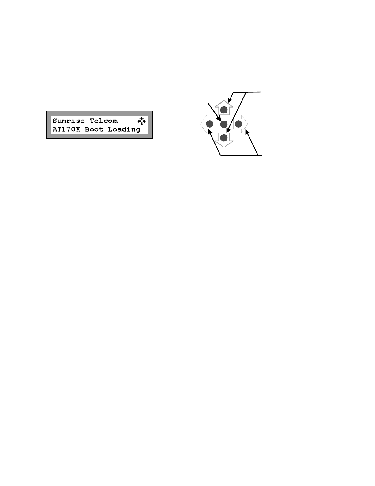
2.4 Close-Up of Controls & Display
Up & Down
Enter /
Select
Left & Right Arrows are for navigation and sequence from screen to screen. Up and Down arrows increment or
decrement the current selected setting. The Center button selects the highlighted item and is used to terminate
changes (Enter).
Change Settings
Left & Right
(Navigation)
Page 7 of 22
AT1700 series Manual D07-00-066P Rev. A00

3 INSTALLATION
3.1 Receiving Instructions
Inspect the shipping container and contents for damage. Notify VeEX Inc. immediately of any shipping damage.
Verify the contents of the package.
Each container should include the following:
AT1701 AT1702
AT1701 or AT1702 Multiplexer 1 1
Power Adapter 1 1
DB9F-to-DB9M cable 6’ 1 2
3.2 Physical Location
The AT1700 series is intended for rack-mount installation, and for indoor use only.
See Operating Specications for environmental requirements. As is general practice, the RF cables should be
kept to a minimum length to minimize their impact on measurement results.
3.3 Electrical Connections
The unit is powered from an external power supply whose input is connected to the AC mains and whose output
is connected to the unit. The power supply is auto-ranging from 100VAC to 240VAC, 47 to 63 Hz.
The AT1700 has no ON-OFF switch. It is powered on or off by connecting or disconnecting the power source,
either at the AC mains or at the DC power connection to the unit.
WARNING! Always use a three-pronged AC power cord (supplied with the product) and insert only into a properly grounded three-pronged receptacle. Failure to ensure proper grounding may expose users to a shock hazard
may damage the product and shall void the warranty.
Note: Any attached equipment (customer supplied) must be grounded to the same protective
ground as the Multiplexer.
3.4 Signal Connections
All signal connections made to both input and output ports (“F” connectors) must:
1. Maintain proper ground continuity.
2. Be stripped of any AC or DC component, common in “cable powering” techniques.
Note: At no time should “cable powering” (24 to 90 VAC or VDC) be applied to any of the signal ports. Doing so may cause irreparable damage to the unit and will void the warranty.
3.5 RS-232 Controller Requirements
There are no specic requirements of the controller other than it must be equipped with an RS-232 communica-
Page 8 of 22
AT1700 series Manual D07-00-066P Rev. A00

tions port and connected with appropriate cabling.
Controller requirements will be dictated by the software application used to control the multiplexer.
Note: Any controller equipment (customer supplied) shall be grounded to the same protective
ground as the Multiplexer.
3.6 Ethernet
Before the Ethernet can be used, the IP address needs to be setup for your network. The default IP address, as
shipped for the factory, is 192.168.1.1. The Ethernet port may be congured from the front panel.
Press the Left or Right arrow keys until the IP address screen is displayed.
Use the Up & Down arrow keys to select STATIC or DHCP.
When STATIC is selected use the Left or Right arrow key to select the 2
nd
line IP address and use the Up and
Down arrows to sequence each digit in the IP address until the desired IP is displayed.
Press ENTER.
In addition, the Subnet Mask and Gateway must be setup.
From the IP Address screen, press the Left or Right arrow key to display the Mask & Gateway setup screen.
Press Enter and then use the Left and Right arrow keys to navigate to the desired digit to edit and use the Up
and Down arrow keys to select the desired digit. Repeat this process for each digit until the desired Subnet Mask
is displayed.
Press ENTER and use the Left and Right arrow keys to select the Gateway IP address and edit it as needed.
If DHCP is selected, the AT1700 will obtain an IP address, Subnet Mask and Gateway from your DHCP server.
Note that setup may now be completed via a simple web browser connection. See the Web
Browser Interface section 4.7.
Page 9 of 22
AT1700 series Manual D07-00-066P Rev. A00

4 FEATURES AND FUNCTIONS
4.1 Buttons
The AT1700 has a group of ve buttons for manual control and to control the conguration of the AT1700 multiplexer.
Left & Right Arrows are for navigation and sequence from screen to screen. Up and Down arrows increment or
decrement the current selected setting. The Center button selects the highlighted item and is used to terminate
changes (Enter).
4.2 Reset
The AT1700 may be returned to the original factory default setting by using the Left or Right arrows to scroll the
display to the “Set Factory Defaults” screen and pressing the center Enter button. This resets all parameters to
the Factory Default setting. Complete conguration is required following this step.
4.3 Test Points
A -20 dB Test Point (female “F” connector) is provided for each Output Port and is located on the front panel for
easy access.
4.4 RF Inputs and Outputs
Sixteen 1 GHz bandwidth RF inputs are provided. The AT1702 has 2 RF outputs, one for each of the internal 16to-1 multiplexers. As a result each output can be independently connected to any one of the shared RF inputs,
passing that signal through to the output at unity gain.
Note: At no time should “cable powering” ( 24 to 90 VAC or VDC) be applied to any of the signal ports. Doing so may cause irreparable damage to the unit and will void the warranty.
4.5 Power In
Power In is provided for powering the unit from the AC adapter provided. No other power source should be utilized unless it is provided by VeEX. An Optional 48 V DC power adapter is available.
Page 10 of 22
AT1700 series Manual D07-00-066P Rev. A00

4.6 RS-232 Communication Ports
Independent communication ports are provided for the A and B Ports of the AT1702.
A single communications port is provided on the AT1701.
The communication inputs for Channel A and Channel B (AT1702 only) connect to a controller using a standard
DB9F-to-DB9M connector “straight through” serial cable.
Note: Connection to an AT2500 uses the same DB9F to DB9M cable.
Note: Connection to a CaLan 3010 requires a DB9M to DB9M “straight through” cable as supplied with the 3010. Also referred to as the “cloning” cable.
The communication Output ports allow chaining the communication link from one unit to the next using a standard DB9F-to-DB9M connector, such that all of the multiplexers are on the same communications link.
Since AT1700 series switches may be physically separated by some distance, cable up to 100 feet or 30 meters
may be used. Depending on the environment, cable may need to be shielded for proper operation. If AT1600
series switches are combined with AT1700 series switches, an RS-232 terminator may be required for proper
operation on long cable installations. Please consult the Product Support group for these special installations.
4.7 Web Browser Interface
Once the Ethernet port is congured, the AT1700 may be connected to the network. Simply enter the IP address
in the URL address bar of your browser. The user may also make all setup and conguration changes via the
web browser interface by entering the default IP address 192.168.1.1 in the URL address bar of your browser.
The current Software version, hardware version, MAC address and serial number of the AT1700 is displayed at
the top of the webpage.
Page 11 of 22
AT1700 series Manual D07-00-066P Rev. A00

Once the Web page is displayed, simply edit the switch conguration for port A and port B. See section 5 for
conguration settings.
Additionally the Ethernet IP setup may be modied directly on the Webpage. Select DHCP or STATIC mode.
If STATIC is selected, enter the desired IP address, Subnet Mask and Gateway and then click on UPDATE IP
CONFIG.
Note: If the IP address is changed, you will need to re-connect your browser to the new IP
address.
When a Firmware Upgrade is required, it may be installed via the webpage interface. Click on the BROWSE
button under Upgrade Firmware and navigate to the new rmware le. When it is displayed in the window, click
on the UPGRADE FIRMWARE button. Be sure not to power off the AT1700 during this process. When upgrade
is complete, a popup message will appear indicating the upgrade was successful.
Page 12 of 22
AT1700 series Manual D07-00-066P Rev. A00

5 OPERATING MODES
5.1 Initial Operation
When the unit is powered on the rmware is loaded prior to any switch capability.
After power-up, the unit will display the current state of each multiplexer.
The AT1701 will display only Port A information (no port B). AT1702 will display both Port A and B. The mode,
Remote or Manual, is displayed along with the current input port number selected.
This condition persists until a front panel key is pressed or until a valid remote command is received on either
Port B: NO Remote
channel. Although displaying no selected input port the unit is in the REMOTE mode and is ready for normal
operation.
5.2 Manual Mode
When the Multiplexer is in the Manual mode, the user may scroll to the desired input Port 1 to 16 using the UP
and DOWN buttons.
The unit can be placed in manual or REMOTE mode by pressing the center ENTER button, using the left or right
arrow to navigate to the desired Port selection and pressing the Up or Down arrow to change the desired setting. .
If the AT1700 is in Manual mode the UI Timeout will begin. If a button is not pressed for the duration of the UI
timeout, the Port will automatically go back to the Remote mode following the specied delay, after the last key
Port B: NO Remote
press. This prevents a user from accidentally leaving the AT1700 in the manual mode and preventing a monitoring system from normal operation.
The user may set the UI Timeout delay. From the main menu, press the left or right arrow key until “UI Timeout” is
displayed. Press the center Enter key to select UI Time out. Us the left and right arrow keys to highlight the digital
to be changed. Press the Up or Down arrows to increment or decrement the desired digit. Press the center Enter
key when the desired delay is shown.
Note: The AT1700 has independent RF Input port controls for Manual and REMOTE modes to
allow switching between modes without affecting the channel selected in the other port.
Page 13 of 22
AT1700 series Manual D07-00-066P Rev. A00

5.3 Remote Mode
When the Multiplexer is in REMOTE mode all unit functionality is controlled through the communications port. All
front panel controls are limited to displaying the current settings, except for the LOCAL/REMOTE function which
may be used to manually change to the Manual mode of operation.
The RF Input Indicators continue to show the selected RF input, as in LOCAL mode (1 to 16).
Port A in the screen above is in Remote mode and currently selecting the input port 5. Port B is in the Manual
mode and current set to input port 1.
Page 14 of 22
AT1700 series Manual D07-00-066P Rev. A00

6 CONFIGURATION MODE
Conguration may be performed manually from the front panel or via the Web Browser interface. See section 4.7
for Web Browser operation.
During boot-up (during power-up or after selecting Factory Defaults) the unit goes through a short process when
the buttons are not accessible.
Since multiple switches may be used in an installation, each output port must have a Switch Address for the
controller to know which switch to control.
Use the Left or Right arrow keys to select the Switch Address screen for Port A and Port B. Press ENTER and
use the Left and Right arrow keys to navigate from Port A to B and vice versa. Use the Up and Down arrow keys
to increment or decrement the port numbers for each output port.
Note: If a switch is used as a combiner for other switches it should be congured as port 1.
In addition, each port must be congured to match its controller. Use the Left or Right arrow keys to select Setup
mode for Port A or Port B.
Or
Press the Enter button to select one of the above and to display the current setting for that Port. Once Conguration Mode has been selected, the AT1700 displays the communicate information for that port. Each Port’s
conguration is independent,
Use the Left and Right arrow keys to navigate to the desired parameter to change and use the Up and Down
arrows to change the setting.
Note: The Baud rate must match the controller device. Typically the highest Baud rate setting
is the most preferred.
There are two Protocol modes, Long and Short. Similarly, select the appropriate Protocol for the controller. Typically Long Protocol for PC and AT2500s as controllers and Short for CaLan 3010 applications.
Page 15 of 22
AT1700 series Manual D07-00-066P Rev. A00

The following chart is from the AT1600 manual as a reference.
Sequence
AT1700
Parameter Settings Comments
Display
1 01 01 Switch Address Switch address
can be set from 1
to 64.
2 P2 Protocol - Port A 1 = Short protocol
2 = Long protocol
3 P2 Protocol - Port B 1 = Short protocol
2 = Long protocol
4 b4 Baud Rate -
Port A
1 = 19.2 KBaud,
2 = 38.4 KBaud,
3 = 57.6 KBaud,
4 = 115.2 KBaud
Use the Up/Down buttons
for the corresponding channel (A or B) to increment or
decrement it’s address.
Press either Mode button
(Channel-A or Channel-B )
to accept the address
Press Channel-A Mode button to accept.
Press Channel-B Mbutton to
accept. (Aonly)
Press Channel-A Mbutton to
accept.
5 b4 Baud Rate -
Port B
1 = 19.2 KBaud,
2 = 38.4 KBaud,
Press Channel-B Mbutton to
accept. (Aonly)
3 = 57.6 KBaud,
4 = 115.2 KBaud
Advance to the next parameter in the sequence by pressing the appropriate button. Following the last parameter, the unit will function as congured, entering REMOTE mode, and the display and buttons return to normal
operation (see 6.1).
Typical settings:
y AT2500
o Protocol Long (2)
o Baud Rate 115.2 KBaud (4)
y CaLan 3010
o Protocol Long (2)
o Baud Rate 38.4 KBaud (2)
Page 16 of 22
AT1700 series Manual D07-00-066P Rev. A00

6.1 UI Timeout Operation
The UI (user interface) Timeout Delay controls whether or not the unit returns to REMOTE mode automatically,
after having been put into LOCAL mode by the user.
With the delay set to 999 seconds, the unit will remain in LOCAL mode indenitely. With any other delay value
(1-998), the unit will automatically return to REMOTE mode, once no keyboard activity has been detected for the
set time delay.
The Auto-remote delay has no bearing on initial boot-up. When the switch boots-up, it is always in remote mode,
ready to receive commands. The auto-remote delay applies only when the switch has been manually put into the
LOCAL mode via the front panel buttons.
If the multiplexer is set into LOCAL mode by a remote controller, it will stay in LOCAL until a front panel key is
pressed or the remote controller resets it to REMOTE mode, initiating the Auto-Remote timer for that output port.
6.2 Trigger Mode
The Trigger Mode allows for more rapid stepping by rst loading an Input Sequence Table and then stepping
through the table by simply toggling the Trigger Line (DTR signal).
There are two update methods available in Trig mode: Leading Update and Trailing Update on RF Hardware rev
1 and later:
Page 17 of 22
AT1700 series Manual D07-00-066P Rev. A00

Trigger mode may only be initiated by a remote controller. In order for a controller to initiate the Trigger Mode, the
following steps must be followed:
1. The multiplexer output port (A or B) must be in REMOTE mode.
2. The host controller must download a valid Input Sequence Table containing a list of 2 to 255 Inputs
3. The controller must send an “Enable Sequence” command to the multiplexer. Following successful receipt of
this command the RF Input Indicators will either show the rst input in the sequence table (Leading Update
mode) or will stay on the current channel (Trailing Update mode). (See AT1700 Protocol Specications for
more details)
4. Sequenced operation is now ready. Each time the controller toggles the trigger line, the multiplexer will advance to the next item in the table. Upon reaching the end of the table, the pointer will wrap around to the
rst item.
The decimal point of the leftmost digit is illuminated to indicate that the unit is in TRIGGER mode.
Page 18 of 22
AT1700 series Manual D07-00-066P Rev. A00

7 SERVICE AND SUPPORT
VeEX Inc. is committed to providing excellent service worldwide. Our goal is to provide you with professional
assistance in the use of our software and services, wherever you are located. Technical Support and Customer
Service solutions vary by country. If you have questions about the services, please refer to the Technical Support
section below.
At VeEX Inc. we get everyone involved and trained to handle Customer service and support requirements. This
assures our customers that there is always someone that can be reached at a moment’s notice. VeEX Inc. also
provides product training to regional representatives allowing them to provide some of the product support locally
and in a prompt and personalized manner.
7.1 Technical Support
Repairs and/or calibration are typically completed in 5 to 10 working days. The factory pays shipping costs only
when returning equipment to a customer following warranty repair. It is the responsibility the customer to notify
the factory technical support persons prior to shipping products for servicing, since many times problems may be
solved over the telephone, saving the user more precious time and shipping costs.
A number and e-mail address for technical and sales support are provided below.
Tel: +1 510 651 0500
Fax: +1 510 651 0505
E-mail: customercare@veexinc.com
Web Site: http://www.veexinc.com
7.2 Warranty Information
This VeEX Inc. product is warranted against defects in materials and workmanship during its warranty period.
The warranty period for this product is contained in the warranty page on http://www.veexinc.com.
VeEX Inc. agrees to repair or replace any assembly or component found to be defective under normal use during
this period. The obligation under this warranty is limited solely to repairing or replacing the product that proves to
be defective within the scope of the warranty when returned to the factory. This warranty does not apply under
certain conditions, as set forth on the warranty page on http://www.veexinc.com. Please refer to the website for
specic details.
THIS IS A LIMITED WARRANTY AND THE ONLY WARRANTY MADE BY VEEX INC. VEEX INC. MAKES NO
OTHER WARRANTY, REPRESENTATION OR CONDITION, EXPRESS OR IMPLIED, AND EXPRESSLY DISCLAIMS THE IMPLIED WARRANTIES OF MERCHANTABILITY, FITNESS FOR A PARTICULAR PURPOSE
AND NON-INFRINGEMENT OF THIRD PARTY RIGHTS.
Page 19 of 22
AT1700 series Manual D07-00-066P Rev. A00

8 PRODUCT SPECIFICATIONS
8.1 GENERAL SPECIFICATIONS
Model AT1701 AT1702
RF Inputs 16 16 Common to both channels
RF Outputs 1 2 Independent
outputs and controls for each channel
Test Points 1 2 One for each channel, located on front
panel
Comm. Ports 3 5 2 Input ports (1 for each channel) and 2
Output ports(1 for each channel) and 1
Ethernet Port
Comm. Port
Type
RS-232 &
Ethernet
RS-232 &
Ethernet
Page 20 of 22
AT1700 series Manual D07-00-066P Rev. A00

8.2 ELECTRICAL SPECIFICATIONS
Parameter Value Tolerance Comments
Pass band (All inputs) 5 – 1 000 MHz NA
Gain AT1701 10 dB ± 1 dB Across the band
Pass band Flatness +0.75
Across the band
Return Loss all inputs 10 dB min 12 dB typical Across the band
Return Loss outputs 13 dB min 15 dB typical Across the band
Maximum Signal level 10 dBmV
Per Channel for
100 channels or +30 dBmV
total power
CTB -60 dBc min -65 dBc typical 100 channels @ 10 dBmV *
CSO -60 dbc -65 dBc typical 100 channels @ 10 dBmV *
Input Crosstalk -50 db min -60 dB typical Across the band
Isolation 16 inputs -50 dB min -60 dB typical Across the band
Switching differential ** ± 0.5 dB max
Noise Figure < 3.0 dB
Operate time, Short
Protocol ***
Operate time, Long
Protocol ***
2.1 msec to
7 msec max
3.9 msec typ
10 msec max
Across the band
Across the band
115.2 kBaud Message +actuation + ACK
With trafc on other com port
115.2 kBaud Message +actuation + ACK
With trafc on other com port
Switching time **** 40 μsec 0.8
msec typ
2.9 msec max
Test Point Loss -20 dB +/- 2 dB
** Variation on one output due to switching of the other output to the same input.
*** Time required for Message reception, processing, switch actuation and ACK transmission.
**** Time required for switch actuation, in Trigger Mode, after the rising edge of hardware trigger (DTR).
Switch actuation
Ready for next
trigger
With trafc on other com port
Page 21 of 22
AT1700 series Manual D07-00-066P Rev. A00

8.3 MECHANICAL & ENVIRONMENTAL SPECIFICATIONS
Parameter Value Tolerance Remark
Size 1 RU x 19” x 12”
Mass 6.6 lb
Temperature, operating 5 to +40 C
Temperature, storage -40 to +70 C
Pollution Degree II
Installation Category II
Altitude Up to 2000m
Humidity 80% up to 31°C
Shock and vibration 3 g maximum
Powering 15 VDC ± 10%
Electrical Supply Class II
Main Supply Voltage
± 10%
Tolerance
Current consumption 1750 mA max
Decreasing linearly to
50% at 40°C
Certied plug-in power
supply rated at 3A minimum.
Main S upply Voltage
indicated on plug-in
power supply.
1750 mA typical @
15VDC
Page 22 of 22
AT1700 series Manual D07-00-066P Rev. A00
 Loading...