

Page 1
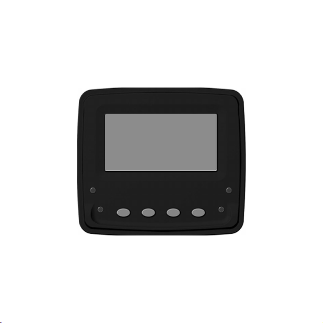
TM
VeeCAN 128
VeeCAN
™
Veethree Engine Monitor
Page 2

Introduction
Thank you for choosing the VeeCAN 128 display.
These pages provide a brief introduction to the VeeCAN 128 display,
™
™
but more importantly the recommended installation instructions. This
display comes installed with Veethree Engine Monitor (VEM) software
which displays J1939-compatible engine/transmission data. Please
read through the guide before use.
The VEM software creates graphical instrument clusters to display
parameters and alarms - providing users with a timesaving solution
for introducing equipment incorporating higher degrees of electronic
display.
We hope that you will be pleased with this product and that you will
have many years of trouble free operation. If you have any problems or
ideas for improvement then we would like to hear from you.
www.v3instruments.com
Page 3

CONTENTS
Section Page
1 ................
2 ................
3 ................
4 ................
5 ................
6 ................
7 ................
8 ................
9 ................
10 ..............
The VeeCAN 128 Platform................................................ 4
VeeCAN 128 Connection Data......................................... 5
Typical J1939 Wiring Topology......................................... 6
VeeCAN 128 Installation................................................... 7
Maintenance and Troubleshooting.................................. 9
Home Screen....................................................................... 10
Alarms Screen..................................................................... 12
Main Menu........................................................................... 13
Glossary................................................................................ 14
Important Safety Information............................................ 15
™
™
™
3
Page 4

1. The VeeCAN 128 Platform
The VeeCAN 128 display is a compact platform that is large enough
™
to support monitoring and diagnostic data available on the latest
generation of electronically controlled systems.
The display offers 4 soft keys, 128 x 64 pixel display area, and 4 warning
lights to signify engine fault/failure. It offers a Deutsh connector
interface and a Mini USB port. Fully sealed to IP 66 (front) and IP 67
(back) with Deutsch connector and rubber USB port plug inserted.
4
Page 5
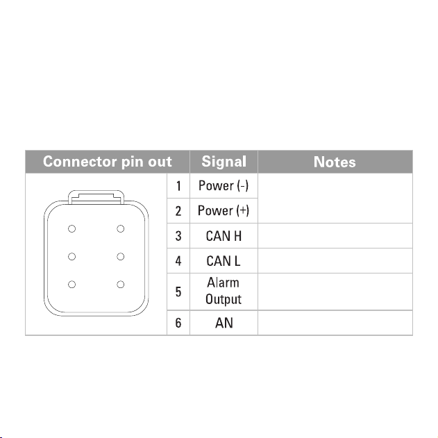
2. VeeCAN 128 Connection Data
The VeeCAN 128 interfaces to data via the Deutsch DT04-6P connector
™
on the rear of the display - wired as shown (see pin out diagram).
Ground and power (10 - 32VDC).
Supply should be protected by
500mA-rated circuit breaker/fuse.
1
6
2
5
34
Primary CAN Data High
Primary CAN Data Low
Low Side Relay Switch to Ground
Analog Input
5
Page 6
3. Typical J1939 Wiring Topology
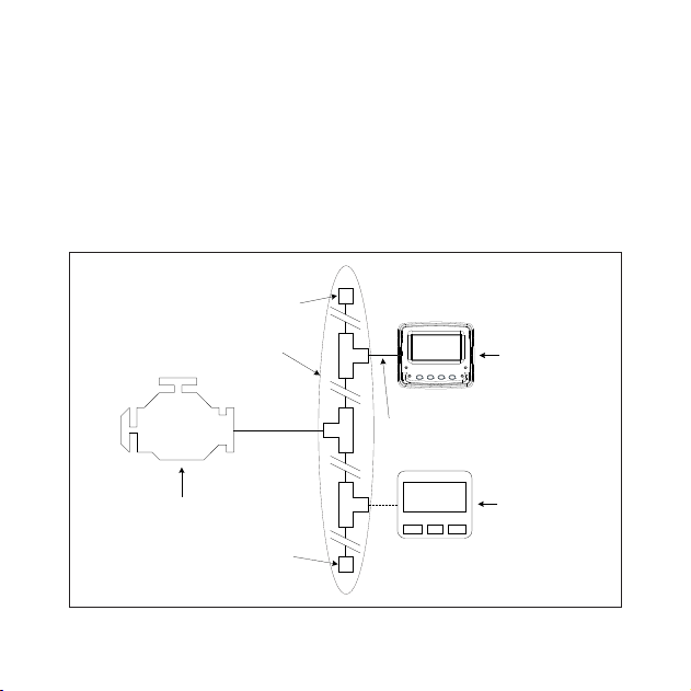
Most modern engine installations include a harness with built-in J1939
backbone, (check engine manufacturer’s documentation). If not, it is
critical to use twisted shielded pair with a drain wire (max length 40m)
terminated with 120 ohm resistors at each end. In addition, all stubs
should not exceed 1m in length, and a maximum of 30 nodes.
Termination
Resistor (120 ohm)
Backbone
(Max length 40m)
Stub (Max length 1m)
VeeCAN 128
Display
Engine and/or
Transmission
Termination
Resistor (120 ohm)
6
Node
(30 max)
Page 7

4. VeeCAN 128 Installation
™
Units are designed to be mounted onto a bulkhead, dashboard, or panel.
The method is described below. The only required components are
the mounting bracket and hardware; these are supplied with every
VeeCAN 128 unit.
™
Instructions:
Decide on a location.
Allow adequate clearance behind the display for cable connection
(to ensure that the cables are not unduly stressed), and for ventilation.
Leave sufficient cable so that the unit may be removed for servicing.
Cut a 2 inch (51 mm) hole.
Screw the studs into the rear case.
Place the VeeCAN 128 in position, use the mounting bracket and
™
thumb nuts to secure the units. The thumb nuts should only be hand
tight.
Connect the Deutsch mating part into the housing.
WARNING: Do not over tighten the studs/thumb nuts and don’t use metal screws
as they may damage the unit and void the warranty.
7
Page 8
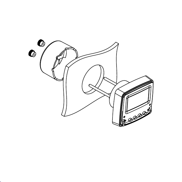
Unit mounting method
8
Page 9
5. Maintenance and Troubleshooting
No regular maintenance is required, except for cleaning the VeeCAN
128 lens as required, using a soft, damp cloth. Do not use abrasive
materials or solvents.
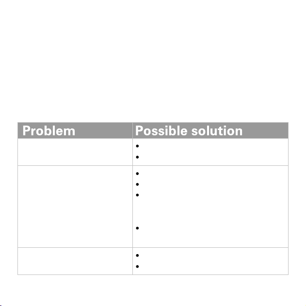
If you are experiencing operating problems with VeeCAN 128 please
™
refer to the following diagnostics:
Unit does not power up
Ensure connections to unit are correct.
Ensure power source is present.
Ensure connections to unit are correct.
Ensure data source is broadcasting data.
Ensure source address in the display matches
Unit fails to display any data
source data being provided by the engine and/or
transmission.
Ensure the J1939 backbone is connected and
terminating resistors are in place.
Unit displays random data
Ensure connections to unit are correct.
Ensure demo mode is off.
™
9
Page 10
6. Home Screen
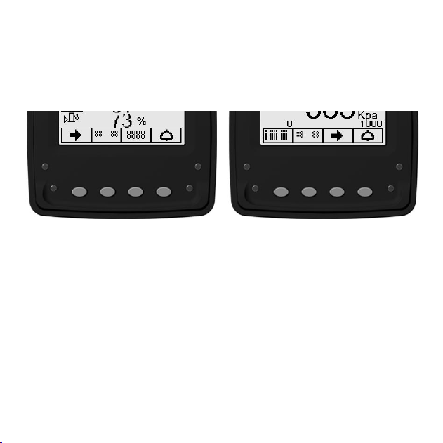
There are 3 main user screens accessed via the first three keys. The
keys have icons to represent the screen view types, as follows.
Key 1 is a quad gauge view, pressing Key 1 repeatedly will cycle
through available quad screens (4 screen max).
Key 2 is a dual gauge view, pressing Key 2 repeatedly will cycle
through available dual screens (4 screen max).
Key 3 is a single gauge view, pressing Key 3 repeatedly will cycle
through available single screens (4 screen max).
NOTE: Number of available screens can be adjusted to 2, 3, or 4
screens for each option.
10
Page 11
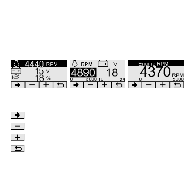
The information that is displayed on the quad, dual, and single screens
can be selected and arranged for better viewing by the operator.
Once in the desired gauge view (quad, dual, single), press and hold
the Key for that view.
Quad Screen Dual Screen SingleScreen
Once the contrast changes use aproperate keys to change available
information.
Key highlights the data to be changed
Key selects previous parameter
Key selects next parameter
Key exits adjust screen (auto timeout aprox 30 sec)
All available screens can be adjusted in this manner.
Note: Bar graph is only available on the dual and single screens, both
the minimum and maximum values can be adjusted.
11
Page 12
7. Alarms Screen
When an alarm condition exists, the information is sent from the engine
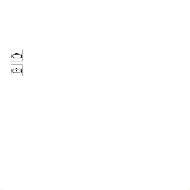
and/or transmission, the information will be displayed via alarm icons,
LEDs, and internal alarm buzzer (and external if connected).
Check Engine - Alarm will sound along with Orange LEDs.
Stop Engine - Alarm will sound along with Red LEDs.
To acknowledge the alarm press Key 4 to acess alarm screen and then
Key 3 to silence the alarm. Pressing Key 4 again will exit alarm screen.
The alarm icons and LEDs will continue to flash until the alarm condition
is resolved and alarm clear command is received from the engine and/or
transmission.
12
Page 13

8. Main Menu
To access the Main Menu of the VeeCAN 128 display, press and hold
Key 4 when at the home screen. Once in the menu use Key 1 and 2 to
navigate selections, Key 3 to enter selection, and Key 4 to go back.
Tier 4 Control - At this screen the user can change Tier 4 modes.
NOTE: Please refer to engine manual for further information regarding
actions required for Tier 4 engines.
Lighting Contract - Used to control the LCD backlight, contrast, and
button backlight.
Settings - Language and Key Tone options can be found here.
Protected Settings - To access Protected Settings use PIN 1234.
In the Protected Settings, the user can change the units, access
Demo Mode, J1939 settings, Service Hours, IO Setup, Restore
Defaults, select Max Quad, Dual, and Single screens.
Diagnostics - Used to access Data Viewer and CAN Diagnostics.
About - Displays software information.
™
13
Page 14

9. Glossary
CAN
Controller Area Network (also referred to as CAN bus);
serial communication protocol for automotive use
VeeCAN 128
™
VEM
Intelligent CAN-compatible LCD display module
Veethree Engine Monitor
J1939 SAE engine data protocol using CAN 2.0B
LCD Liquid Crystal Display
Soft keys Push-button keys whose function changes according
to use.
14
Page 15

10. Important Safety and Legal Information
Under no circumstances shall Veethree or any of its subsidiary
companies accept liability for any loss of data, income, incidental
damage or consequential losses incurred as a result of the use of the
product, howsoever caused when used as a monitor for electronically
controlled engines/transmissions or other systems.
Veethree operates a policy of continuous improvement. Veethree
reserves the right to alter and improve the VeeCAN 128 displays and
software without prior notice.
CE EMC Directive 2004/108/EC
This product has been designed to be compliant with this directive.
Compliance can only be ensured by correct installation.
™
VeeCAN
is a Registered Trademark of Veethree Electronics and Marine LLC
™
15
Page 16

2050 47th Terrace East, Bradenton , Florida 34203 USA
Veethree Electronics and Marine LLC
www.v3instruments.com | 1-941-538-7775 | Fax: 1-941-755-1222
70617 Rev. 1
VeeCAN 128
™
VEETHREE ENGINE MONITOR
 Loading...