

Veethree EGM Installation Manual
1
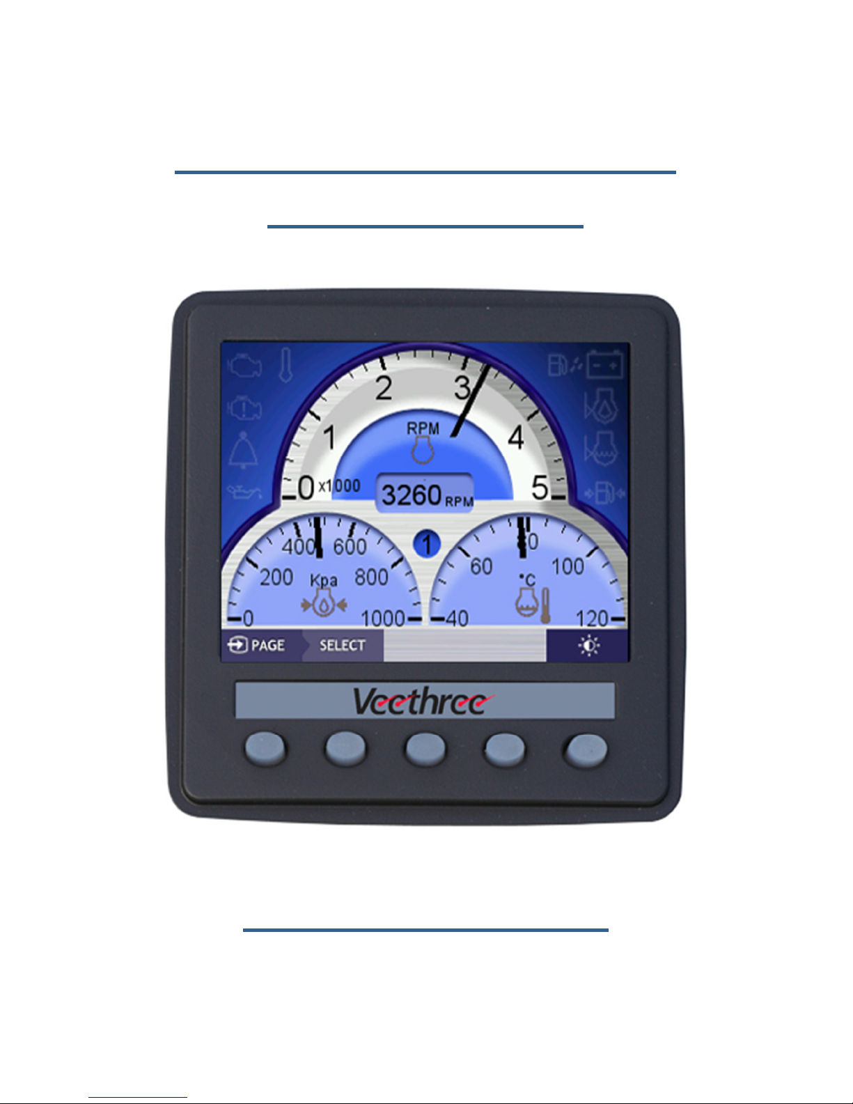
Marine Engine Gateway
Monitor (EGM)
Installation Guide

2
Contents
1. Installing the Displays ............................................................................... 3
1.1 Mounting the Display .............................................................................. 3
1.2 Power Connections to the Display (all engine types) ............................. 3
1.3 Attaching to NMEA 2000 (optional) ........................................................ 3
1.4 Attaching to a J1939 Engines (CAN-bus) ................................................. 4
1.5 Attaching to an Engine via Analogue Signals .......................................... 4
1.6 Attaching to a Rudder Angle Sender ....................................................... 4
1.7 Attaching to a Fuel Level Sender ............................................................. 5
1.8 Attaching to a Trim/Tilt Sender ............................................................... 5
1.9 Attaching to a GPS NMEA 0183 Signal .................................................... 5
2 Commissioning the System ............................................................................ 6
2.1 ‘System Configuration’ Menu ................................................................. 6
2.2 Engine ID ............................................................................................. 7
2.2 Data Sources ....................................................................................... 7
2.3 NMEA 2000 Settings............................................................................ 9
2.4 J1939 Settings ................................................................................... 10
2.5 Analogue Settings ............................................................................. 11
2.6 Fuel Management Settings ............................................................... 13
2.7 Diagnostics ........................................................................................ 14

3
1. Installing the Displays
The EGM supports up to three engine types (Non-electric, J1939 or NMEA
2000) and each display can be allocated to be Port (or single), Starboard or
Centre. When mounting the displays the allocation of position is not
important as this is done during the commissioning sequence. Multi station
capability is a built-in feature and is provided across the NMEA 2000 network
using the gateway function. Adjustable items like language selection and
backlight are shared across the network so that all displays are synchronised
with the same settings.
1.1 Mounting the Display
Contained in the box you have received is a Fixing template, place this on the
area where the display is to be fitted, and use it to mark the holes in the
Dash, Fit the studding, from the “Fitting Kit” supplied, into the four positions
at the rear of the display. Make sure the Rubber Seal is securely in place at
the rear of the display over the USB Port access and then feed the studding
through the four holes and use the nuts to fix the display in place. The display
has an integrated rubber gasket to help seal the display to the dash.
Depending on access you may also need to fit the supplied cable harness to
the display before mounting the display.
1.2 Power Connections to the Display (all engine types)
The display can be powered from the engine battery, this way the display will
be able to monitor the engine battery voltage, however, while the engine is
cranking the display may cut out. Alternatively you can connect the display to
the domestic battery supply; this will prevent cut outs while the engine is
cranking. In either case the supply is fed via the black and red wires on the
harness (there are two blacks and either can be used). The supply should be
fused at 500mA or 1A max to protect the wiring.
1.3 Attaching to NMEA 2000 (optional)
Find the NMEA 2000 backbone if already fitted on the vessel, and use a TPiece to connect the NMEA 2000 Cable from the display to the backbone. You
should check that the NMEA backbone is properly terminated, you do this by
4
finding each end, and making sure they have a NMEA 2000 termination
device at each end of the backbone. If there is no pre-existing backbone you
will need to fit this before connecting the display. If you have a dual station
system you will need to connect to the NMEA 2000 network to share data
between EGM’s even if you don’t have any other NMEA 2000 equipment.
1.4 Attaching to a J1939 Engines (CAN-bus)
You will need to find the CAN-Low and the CAN-High from the Engine ECU or
off of the Transmission – see engine manual for this information. You will
then need to connect the Blue wire to the CAN-Low and the White wire to
the CAN-High. They should remain twisted together. You will also want to
check that the J1939 CAN Network is properly terminated. (You can do this
by measuring the resistance between CAN-High and CAN-Low. Once
connected it should read around 90-150 Ohms if it does not, you will need to
add a 120 Ohm resistor between the CAN-High and the CAN-Low).
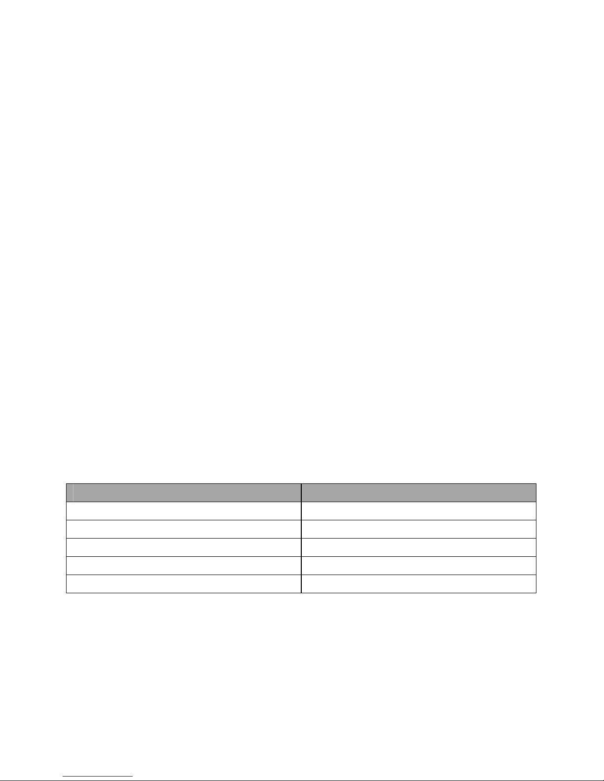
1.5 Attaching to a Non-electronic Engine
In this case the engine senders will be directly connected to the display
harness. The standard minimum is for Engine Speed (Tacho), Oil Pressure and
Coolant Temperature. The display will also measure engine hours (when the
RPM is greater than 400) and battery voltage of the supply it’s connected to
(engine battery or domestic) without additional connections as these are
Automatic.
Wire
Sensor Signal
Black/White
Oil Pressure
Brown/White
Coolant Temperature
Red/White
Boost Pressure
Yellow
Oil Temperature
Violet
Tachometer (from Alternator
W)
1.6 Attaching to a Rudder Angle Sender
The rudder angle can be measured from the Veethree rudder angle sender.
Connect the signal from the sender to the Yellow/White wire of the display

5
harness. The rudder sensor ground is connected to the spare black wire from
the display (used for all analogue senders).
1.7 Attaching to a Fuel Level Sender
The fuel level (one tank per display) can be measured from standard two wire
fuel senders. The sender signal should be connected to the blue wire of the
display harness. The sender ground is connected to the spare black wire from
the display (used for all analogue senders).
1.8 Attaching to a Trim/Tilt Sender
The tilt/trim (one per display) can be measured from standard two wire
tilt/trim senders. The sender signal should be connected to the orange wire
of the display harness. The sender ground is connected to the spare black
wire from the display (used for all analogue senders).
1.9 Attaching to a GPS NMEA 0183 Signal
A NMEA 0183 GPS can be attached to the unit to allow is to display SOG
(speed over ground) and COG (course over ground). The NMEA 0183 transmit
of the GPS should be linked with the green wire of the display harness.
 Loading...