

Page 1

OBDCheck
VP
OBDII/EOBD SCAN TOOL
39
User Manual
The Best Solution to Read & Erase Trouble
Codes for OBD II Compliant Vehicles.
Page 2

Table of Contents
1. Safety Precautions and Warnings........................................................................1
2. General Information
2.1 On-Board-Diagnostics (OBD) II...............................................................................1
2.2 Diagnostic Trouble Codes (DTCs)...........................................................................2
2.3 Location of the Data Link Connector (DLC).............................................................2
2.4 OBD II Readiness Monitors.....................................................................................3
2.5 OBD II Monitor Readiness Status............................................................................3
2.6 OBD II Denitions...................................................................................................4
3. Product Information
3.1 Tool Description .....................................................................................................5
3.2 Product Specications ...........................................................................................6
3.3 Accessories Included .............................................................................................6
3.4 Navigation Characters ............................................................................................6
3.5 Vehicle Power ........................................................................................................6
3.6 Product Setup ........................................................................................................6
3.7 Vehicle Coverage ...................................................................................................9
4. OBD II Diagnostics ................................................................................................9
4.1 Reading Codes.....................................................................................................10
4.2 Erasing Codes.......................................................................................................11
4.3 Viewing Freeze Frame Data ...................................................................................12
4.4 Retrieving I/M Readiness Status............................................................................13
4.5 Viewing Vehicle Information..................................................................................15
4.6 Exiting OBDII Test..................................................................................................16
Warranty and Service.................................................................................Back Cover
Page 3

1. Safety Precautions and Warnings
To prevent personal injury or damage to vehicles and/or the scan tool, please read this
manual rst and follow the following safety instructions whenever working on a vehicle:
• Always perform automotive testing in a safe environment.
• Wear safety eye protection that meets ANSI standards.
• Keep clothing, hair, hands, tools, test equipment, etc, away from all moving or hot
engine parts.
• Operate the vehicle in a well-ventilated work area; Exhaust gases are poisonous.
• Put blocks on drive wheels and never leave vehicle unattended while running tests.
• Use extreme caution when working around the ignition coil, distributor cap, ignition
wires and spark plugs. These components create hazardous voltages when the engine is
running.
• Put transmission in PARK (for automatic transmission) or NEUTRAL (for manual
transmission) and make sure the parking brake is engaged.
• Keep a re extinguisher suitable for gasoline/chemical/ electrical res nearby.
• Don’t connect or disconnect any test equipment with ignition on or engine running.
• Keep the scan tool dry, clean and free from oil, water and grease. Use a mild detergent
on a clean cloth to clean the outside of the Scan Tool, when necessary.
2. General Information
2.1 On-Board-Diagnostics (OBD) II
The rst generation of On-Board Diagnostic (called OBD I), was developed by the
California Air Resources Board (ARB) and implemented in 1988 to monitor some of the
emission control components on vehicles. As technology evolved and the desire to
improve the OBD I system increased, a new generation of On-Board Diagnostics system
was developed. This second generation of On-Board Diagnostic regulations is called
"OBD II".
The OBD II system is designed to monitor emission control systems and key engine
components by performing either continuous or periodic tests of specic components
and vehicle conditions. When a problem is detected, the OBD II system turns on a
warning lamp (MIL) on the vehicle instrument panel to alert the driver typically by the
phrase of “Check Engine” or “Service Engine Soon”. The system will also store
important information about the detected malfunction so that a technician can accurately
nd and x the problem. Here below follow three pieces of such valuable information:
• Whether the Malfunction Indicator Light (MIL) is commanded 'on' or 'off';
• Which, if any, Diagnostic Trouble Codes (DTCs) are stored;
• Readiness Monitor Status.
- 1 -
Page 4

2.2 Diagnostic Trouble Codes (DTCs)
OBD II Diagnostic Trouble Codes are codes that are stored by the on-board computer
diagnostic system in response to a problem found in the vehicle. These codes identify a
particular problem area and are intended to provide you with a guide as to where a fault
might be occurring within a vehicle. OBD II Diagnostic Trouble Codes consist of a
ve-digit alphanumeric code. The rst character, a letter, identies the control system
which sets the code. The other four characters, all numbers, provide additional
information on where the DTC originated and the operating conditions that caused it to
set. Here below is an example to illustrate the structure of the digits:
DTC Example
P 0 2 0 2
Systems
B=Body
C=Chassis
P=Powertrain
U=Network
2.3 Location of the Data Link Connector (DLC)
The DLC (Data Link Connector or Diagnostic Link Connector) is the standardized
16-cavity connector where diagnostic code readers interface with the vehicle's on-board
computer. The DLC is usually located 12 inches from the center of the instrument panel
(dash), under or around the driver’s side for most vehicles. If Data Link Connector is not
located under dashboard, a label should be there telling location. For some Asian and
European vehicles, the DLC is located behind the ashtray and the ashtray must be
removed to access the connector. If the DLC cannot be found, refer to the vehicle’s
service manual for the location.
Code Type
Generic (SAE):
P0, P2, P34-P39
B0, B3
C0, C3
U0, U3
Manufacturer Specic:
P1, P30-P33
B1, B2
C1, C2
U1, U2
Sub-systems
1=Fuel and Air metering
2=Fuel and Air metering
3=Ignition System or Engine Misre
4=Auxiliary Emission Controls
5=Vehicle Speed Control and Idle Controls
6=Computer Output Circuits
7=Transmission Controls
8=Transmission Controls
- 2 -
Identifying Specic
Malfunctioning Section
of the Systems
Page 5

2.4 OBD II Readiness Monitors
An important part of a vehicle’s OBDII system is the Readiness monitors, which are
indicators used to nd out if all of the emissions components have been evaluated by the
OBD II system. They are running periodic tests on specic systems and components to
ensure that they are performing within allowable limits.
Currently, there are eleven OBD II Readiness Monitors (or I/M Monitors) dened by the
U.S. Environmental Protection Agency (EPA). Not all monitors are supported by all
vehicles and the exact number of monitors in any vehicle depends on the motor vehicle
manufacturer’s emissions control strategy.
Continuous Monitors -- Some of the vehicle components or systems are continuously
tested by the vehicle’s OBDII system, while others are tested only under specic vehicle
operating conditions. The continuously monitored components listed below are always
ready:
1. Misre
2. Fuel System
3. Comprehensive Components (CCM)
Once the vehicle is running, the OBDII system is continuously checking the above
components, monitoring key engine sensors, watching for engine misre, and
monitoring fuel demands.
Non--Continuous Monitors -- Unlike the continuous monitors, many emissions and
engine system components require the vehicle to be operated under specic conditions
before the monitor is ready. These monitors are termed non-continuous monitors and
are listed below:
1. EGR System
2. O2 Sensors
3. Catalyst
4. Evaporative System
5. O2 Sensor Heater
6. Secondary air
7. Heated Catalyst
8. A/C system
2.5 OBD II Monitor Readiness Status
OBDII systems must indicate whether or not the vehicle’s PCM’s monitor system has
completed testing on each component. Components that have been tested will be
- 3 -
Page 6

reported as “Ready”, or “Complete”, meaning they have been tested by the OBDII
system. The purpose of recording readiness status is to allow inspectors to determine if
the vehicle’s OBDII system has tested all the components and/or systems.
The powertrain control module (PCM) sets a monitor to “Ready” or “Complete” after an
appropriate drive cycle has been performed. The drive cycle that enables a monitor and
sets readiness codes to “ready” varies for each individual monitor. Once a monitor is set
as “Ready” or “Complete”, it will remain in this state. A number of factors, including
erasing of diagnostic trouble codes (DTCs) with a scan tool or a disconnected battery,
can result in Readiness Monitors being set to “not ready”. Since the three continuous
monitors are constantly evaluating, they will be reported as “Ready” all of the time. If
testing of a particular supported non-continuous monitor has not been completed, the
monitor status will be reported as “Not Complete” or “Not Ready.”
In order for the OBD monitor system to become ready, the vehicle should be driven under
a variety of normal operating conditions. These operating conditions may include a mix
of highway driving and stop and go, city type driving, and at least one overnight-off
period. For specic information on getting your vehicle’s OBD monitor system ready,
please consult your vehicle owner’s manual.
2.6 OBD II Denitions
Powertrain Control Module (PCM) -- OBD II terminology for the on-board computer
that controls engine and drive train.
Malfunction Indicator Light (MIL) -- Malfunction Indicator Light (Service Engine Soon,
Check Engine) is a term used for the light on the instrument panel. It is to aler t the driver
and/or the repair technician that there is a problem with one or more of vehicle's
systems and may cause emissions to exceed federal standards. If the MIL illuminates
with a steady light, it indicates that a problem has been detected and the vehicle should
be serviced as soon as possible. Under certain conditions, the dashboard light will blink
or ash. This indicates a severe problem and ashing is intended to discourage vehicle
operation. The vehicle onboard diagnostic system can not turn the MIL off until the
necessary repairs are completed or the condition no longer exists.
DTC -- Diagnostic Trouble Codes (DTC) that identify which section of the emission
control system has malfunctioned.
Enabling Criteria -- Also termed Enabling Conditions. They are the vehicle-specic
events or conditions that must occur within the engine before the various monitors will
set, or run. Some monitors require the vehicle to follow a prescribed “drive cycle”
routine as part of the enabling criteria. Drive cycles vary among vehicles and for each
monitor in any particular vehicle.
OBD II Drive Cycle -- A specic mode of vehicle operation that provides conditions
required to set all the readiness monitors applicable to the vehicle to the “ready”
- 4 -
Page 7
condition. The purpose of completing an OBD II drive cycle is to force the vehicle to run
its onboard diagnostics. Some form of a drive cycle needs to be performed after DTCs
have been erased from the PCM’s memory or after the battery has been disconnected.
Running through a vehicle’s complete drive cycle will “set” the readiness monitors so
that future faults can be detected. Drive cycles vary depending on the vehicle and the
monitor that needs to be reset. For vehicle specic drive cycle, consult the vehicle’s
Owner’s Manual.
Freeze Frame Data -- When an emissions related fault occurs, the OBD II system not
only sets a code but also records a snapshot of the vehicle operating parameters to help
in identifying the problem. This set of values is referred to as Freeze Frame Data and may
include important engine parameters such as engine RPM, vehicle speed, air ow,
engine load, fuel pressure, fuel trim value, engine coolant temperature, ignition timing
advance, or closed loop status.
3. Product Information
3.1 Tool Description
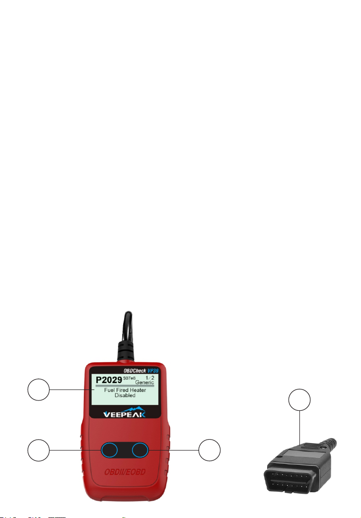
1. LCD DISPLAY--Indicates test results.
2. ENTER/EXIT BUTTON--Conrms a selection (or action) from a menu list, or returns to
the main menu.
3. SCROLL BUTTON-- Scrolls through menu items. It is also usedto enter system setup
menu when pressed.
4. OBD II CONNECTOR--Connects the scan tool to the vehicle’s Data Link Connector
(DLC).
1
2
Ente r
/Exi t
Scro ll
4
»
- 5 -
3
Page 8

3.2 Product Specications
• Display–Backlit, 128 x 64 pixel display
• Operating Temperature--0 to 60°C (32 to 140 F°)
• Storage Temperature-- -20 to 70°C (-4 to 158 F°)
• Power–8 to 18 Volts provided via vehicle battery
• Dimensions: Length /110.3mm (4.34"), Width /69.5mm (2.74"), Height/20.2mm (0.8")
• Weight: 180g (6.35oz)
3.3 Accessories Included
• User’s Manual
• Fixed OBD2 Cable
3.4 Navigation Characters
Characters used to help navigate the code reader are:
• “►” -- Indicates current selection.
• “Pd” -- Identies a pending DTC when viewing DTCs.
• “$” -- Identies the control module number from which the datais retrieved.
3.5 Vehicle Power
The power of the code reader is provided via the vehicle Data Link Connector (DLC).
Follow the steps below to turn on the code reader:
1) Connect the OBD II cable to the code reader.
2) Find DLC on vehicle.
• A plastic DLC cover may be found for some vehicles and you need to remove it before
plugging the OBD2 cable.
3) Plug OBD II cable to the vehicle’s DLC.
3.6 Product Setup
The code reader allows you to make the following adjustments and settings:
1)Language: Selects desired language.
2)Unit of measure: Sets the unit of measure to English or Metric.
3)Contrast adjustment: Adjusts the contrast of the LCD display.
• The Settings of the unit will remain until change to the existing settings is made.
To Enter the Setup Menu
From the second startup screen, press SCROLL button to enter System Setup menu.
- 6 -
Page 9
Follow the instructions to make adjustments and settings as described in the following
setup options.
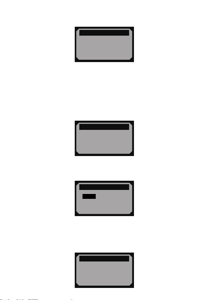
System Setup
= = = = = = = = = = =1/4
►
1) Language
2) Unit of Measure
3) Contrast
4) Exit
• The number "x/x" to the upper right corner of the screen indicates total number of
items under the menu and sequence of currently selected item.
Language Setup
• English is the default language.
1) From System Setup menu, use SCROLL button to select Language, and press
ENTER/EXIT button.
System Setup
= = = = = = = = = = =1/4
►
1) Language
2) Unit of Measure
3) Contrast
4) Exit
2) Use SCROLL button to select the desired language and press ENTER/EXIT button to
save your selection and return to previous menu.
Language
= = = = = = = = = = =1/3
►
English
Français
Español
Unit of Measurement
• Metric is the default measurement unit.
1) From System Setup menu, use SCROLL button to select Unit of Measure and press
ENTER/EXIT button.
System Setup
= = = = = = = = = = =2/4
1) Language
►
2) Unit of Measure
3) Contrast
4) Exit
- 7 -
Page 10
2) From Unit of Measure menu, use SCROLL button to select the desired unit of
measurement.
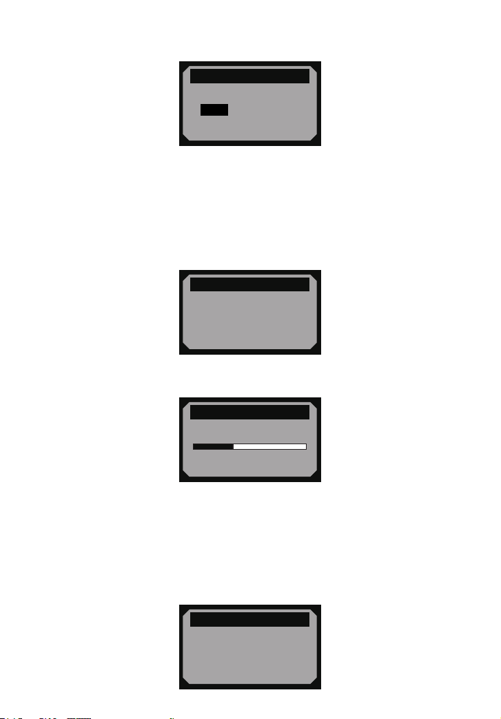
Unit of Measure
= = = = = = = = = = =2/2
English
►
Metric
3) Press ENTER/EXIT button to save your selection and return to previous menu.
Contrast Adjustment
1) From System Setup menu, use SCROLL button to select Contrast, and press
ENTER/EXIT button.
System Setup
= = = = = = = = = = =3/4
1) Language
2) Unit of Measure
►
3) Contrast
4) Exit
2) From Contrast menu, use SCROLL button to adjust contrast.
= = = = = = = = = = = = =
Contrast (35%)
Contrast
Use to change
«
3) Press ENTER/EXIT button to save your settings and return to previous menu.
Exiting System Setup
1) Use SCROLL button to select Exit and press ENTER/EXIT button to return to startup
menu.
System Setup
= = = = = = = = = = =4/4
1) Language
2) Unit of Measure
3) Contrast
►
4) Exit
- 8 -
Page 11

3.7 Vehicle Coverage
The Veepeak VP39 OBDII/EOBD Scanner is specially designed to work with all OBD II
compliant vehicles, including those equipped with latest CAN protocol -- Control Area
Network. It is required by EPA that all 1996 and newer vehicles (cars and light trucks)
sold in the United States must be OBD II compliant and this includes all Domestic, Asian
and European vehicles.
A small number of 1994 and 1995 model year gasoline vehicles are OBD II compliant.
For your vehicle to be OBD II compliant it must have a 16-pin DLC (Data Link Connector)
under the dash and the Vehicle Emission Control Information Label must state that the
vehicle is OBD II compliant.
Different countries start to enforce OBD2 compliance in different years. For Canada, the
year is 1998. And for European Union (EOBD), it's 2001 for gas and 2004 for diesel.
Check with your local authority if you are in other regions.
4. OBD II Diagnostics
When more than one vehicle control module is detected by thescan tool, you will be
prompted to select the module where thedata may be retrieved. The most often to be
selected are thePowertrain Control Module [PCM] and Transmission Control Module
[TCM].
CAUTION: Don't connect or disconnect any test equipment with ignition on or engine
running.
1) Turn the ignition off.
2) Locate the vehicle's 16-pin Data Link Connector (DLC).
3) Plug into the OBDII cable to the vehicle's DLC.
4) Turn the ignition on. Engine can be off or running.
5) Press ENTER/EXIT button to enter Diagnostic Menu. A sequence of messages
displaying the OBD2 protocols will be observed on the display until the vehicle protocol
is detected.
► If the code reader fails to communicate with the vehicle's ECU (Engine Control
Unit), a "LINKING ERROR!" message shows up on the display.
» Verify that the ignition is ON;
» Check if the code reader's OBD II connector is securely connected to the vehicle's DLC;
» Verify that the vehicle is OBD2 compliant;
» Turn the ignition off and wait for about 10 seconds. Turn the ignition back to on and
repeat the procedure from step 5.
» If the "LINKING ERROR" message does not go away, then there might be problems for
the code reader to communicate with the vehicle. Contact your local distributor or the
- 9 -
Page 12
manufacturer's customer service department for assistance.
6) After the system status is displayed (MIL status, DTC counts,Monitor status), wait a
few seconds or press any key for Diagnostic Menu to come up.
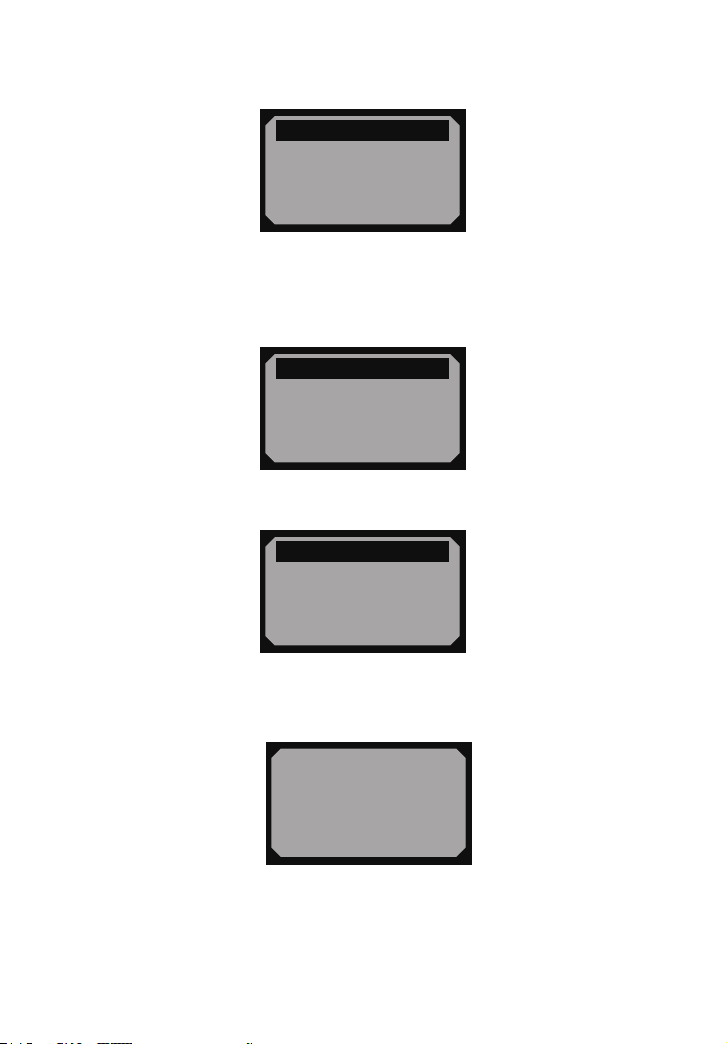
System Status
= = = = = = = = = = = = =
Codes Found 1
Monitors N/A 4
Monitors OK 3
Monitors INC 3
4.1 Reading Codes
1) Use SCROLL button to select Read Codes from Diagnostic Menu and press
ENTER/EXIT button.
Diagnostic Menu
= = = = = = = = = = =1/6
►
1) Read Codes
2) Erase Codes
3) View Freeze Frame
4) I/M Readiness
• If more than one module is detected, you will be prompted to select a module before
test.
Diagnostic Menu
= = = = = = = = = = =1/6
►
1) Read Codes
2) Erase Codes
3) View Freeze Frame
4) I/M Readiness
• Use SCROLL button to select a module, and press ENTER/EXIT button.
2) View DTCs and their denitions on screen.
$11 Pd 1/6
P0115
= = = = = = = = = = = =
►
1) Read Codes
2) Erase Codes
3) View Freeze Frame
4) I/M Readiness
Generic
• The control module number, sequence of the DTCs, total number of codes detected
and type of codes (Generic or Manufacturer specic, Stored or Pending codes) will be
observed on the upper right hand corner of the display.
3) If more than one DTC is found, use SCROLL button, as necessary, until all the codes
have been shown up.
- 10 -
Page 13
• If no codes are detected, a "No codes are stored in the module!" message displays on
the screen.
• If retrieved DTCs contain any manufacturer specic or enhanced codes, the display
indicates "Manufacturer control".
$09 4/6
P1324
= = = = = = = = = = = =
Manufacturer control
Other
4) Press ENTER/EXIT button to return to previous menu.
4.2 Erasing Codes
CAUTION: Erasing the Diagnostic Trouble Codes may allow the code reader to delete
not only the codes from the vehicle’s on-board computer, but also “Freeze Frame” data
and manufacturer enhanced data. Further, the I/M Readiness Monitor Status for all
vehicle monitors is reset to Not Ready or Not Complete status. Do not erase the codes
before the system has been checked completely by a technician.
• This function is performed with key on engine off (KOEO). Do not start the engine.
1) If you decide to erase the DTCs, use SCROLL button to select Erase Codes from
Diagnostics Menu and press ENTER/EXIT button.
Diagnostic Menu
= = = = = = = = = = =2/6
1) Read Codes
►
2) Erase Codes
3) View Freeze Frame
4) I/M Readiness
2) A warning message comes up asking for your conrmation.
Erase Codes
= = = = = = = = = = = = =
Erase trouble codes!
Are you sure?
Yes No
3) If you want to proceed with erasing the codes, press ENTER/EXIT button to erase.
• If the codes are cleared successfully, an “Erase Done!” message shows up.
- 11 -
Page 14
• If the codes are not cleared, then an “Erase Failure. Turn Key on with Engine off!”
message displays.
4) Wait a few seconds or press any key to return to Diagnostic Menu.
• If you do wish to proceed to erase the codes, then press SCROLL button to select NO
and press ENTER/EXIT. A “Command Canceled” message shows up. Press any key or
wait a few seconds to return to Diagnostic Menu.
5) Some codes cannot be erased unless the issue with the vehicle is xed.
4.3 Viewing Freeze Frame Data
1) To view freeze frame, use SCROLL button to select View Freeze Frame from
Diagnostic Menu and press ENTER/EXIT button.
Diagnostic Menu
= = = = = = = = = = =3/6
1) Read Codes
2) Erase Codes
►
3) View Freeze Frame
4) I/M Readiness
• If more than one module is detected, you will be prompted to select a module before
test.
Control Module
= = = = = = = = = = =1/3
►
Engine
Module $A4
Exit
• Use SCROLL button to select a module and press ENTER/EXIT button.
2) Wait a few seconds while the code reader validates the PID MAP.
View Freeze Frame
= = = = = = = = = = = = =
Reading PID.01
- Please Wait -
3) If the retrieved information covers more than one screen, use SCROLL button, as
necessary, until all data have been shown up.
- 12 -
Page 15
View Freeze Frame
= = = = = = = = = = = =1/4
DTCFRZF P2770
FUELSYS1 OL
FUELSYS2 N/A
LOAD_PCT (%) 0.0
• The number “x/x” to the upper right corner of the screen indicates total number of
screens the retrieved freeze frame covers and sequence of currently displayed data.
• If there is no freeze frame data available, an advisory message “No Freeze Frame
Data Stored!” shows on the display.
4) Press ENTER/EXIT to return to Diagnostic Menu.
4.4 Retrieving I/M Readiness Status
I/M Readiness function is used to check the operations of the Emission System on
OBD2 compliant vehicles. It is an excellent function to use prior to having a vehicle
inspected for compliance to a state emissions program.
Some latest vehicle models may support two types of I/M Readiness tests:
• Since DTCs Cleared - indicates status of the monitors since the DTCs are erased.
• This Drive Cycle - indicates status of monitors since the beginning of the current drive
cycle.
An I/M Readiness Status result of “NO” does not necessarily indicate that the vehicle
being tested will fail the state I/M inspection. For some states, one or more such
monitors may be allowed to be “Not Ready” to pass the emissions inspection.
• “OK” -- Indicates that a particular monitor being checked has completed its diagnostic
testing.
• “INC” -- Indicates that a particular monitor being checked has not completed its
diagnostic testing.
• “N/A” -- The monitor is not supported on that vehicle.
1) Use SCROLL button to select I/M Readiness from Diagnostic Menu and press
ENTER/EXIT.
Diagnostic Menu
= = = = = = = = = = =4/6
1) Read Codes
2) Erase Codes
3) View Freeze Frame
►
4) I/M Readiness
• If more than one module is detected, you will be prompted to select a module before
test.
- 13 -
Page 16
Control Module
= = = = = = = = = = =1/3
►
Engine
Module $A4
Exit
• Use the SCROLL button to select a module, and press ENTER/EXIT button.
2) Wait a few seconds while the code reader validates the PID MAP.
I/M Readiness
= = = = = = = = = = = = =
Reading PID...
- Please Wait -
3) If the vehicle supports both types of tests, then both types shows on the screen for
selection.
I/M Readiness
= = = = = = = = = = = =1/3
►
Since DTCs Cleared
This Drive Cycle
Exit
4) Use SCROLL button to view the status of the MIL light (“ON” or “OFF”) and the
following monitors:
• Misre monitor -- Misre monitor
• Fuel System Mon -- Fuel System Monitor
• Comp. Component -- Comprehensive Components Monitor
• EGR -- EGR System Monitor
• Oxygen Sens Mon -- O2 Sensors Monitor
• Catalyst Mon -- Catalyst Monitor
• EVAP System Mon -- Evaporative System Monitor
• Oxygen Sens htr --O2 Sensor Heater Monitor
• Sec Air System -- Secondary Air Monitor
• Htd Catalyst -- Heated Catalyst Monitor
• A/C Refrig Mon -- A/C system Monitor
Since DTCs Cleared
= = = = = = = = = = = =1/3
MIL Status OFF
Misre Monitor OK
Fuel System Mon. OK
Comp. Component OK
- 14 -
Page 17
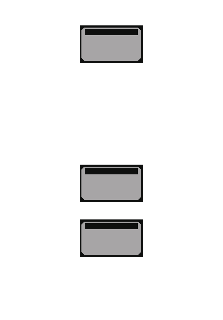
5) If the vehicle supports readiness test of “This Drive Cycle”, a screen of the following
will be displayed:
This Drive Cycle
= = = = = = = = = = = =1/3
MIL Status ON
Misre Monitor OK
Fuel System Mon. OK
Comp. Component OK
• The number “x/x” to the upper right corner of the screen indicates total number of
screens the retrieved data cover and sequence of currently displayed data.
6) Press ENTER/EXIT button to return to previous menu.
4.5 Viewing Vehicle Information
The Vehicle Info. function enables retrieval of the Vehicle Identication No. (VIN),
Calibration ID Nos. (CINs), Calibration Verication Nos. (CVNs) and In-use Performance
Tracking on 2000 and newer vehicles that support Mode 9.
1) Use SCROLL button to select Vehicle Info. from Diagnostic Menu and press
ENTER/EXIT button.
Diagnostic Menu
= = = = = = = = = = = =5/6
►
5) Vehicle Info.
6) Exit
2) Wait a few seconds or press ENTER/EXIT button to continue.
Vehicle Info.
= = = = = = = = = = = = =
Turn key on
with engine off!
Press [ENTER] to con.
• If the vehicle does not support this mode, a “The selected mode is not supported!”
message shows on the display.
• If more than one module is detected, you will be prompted to select a module before
test.
- 15 -
Page 18
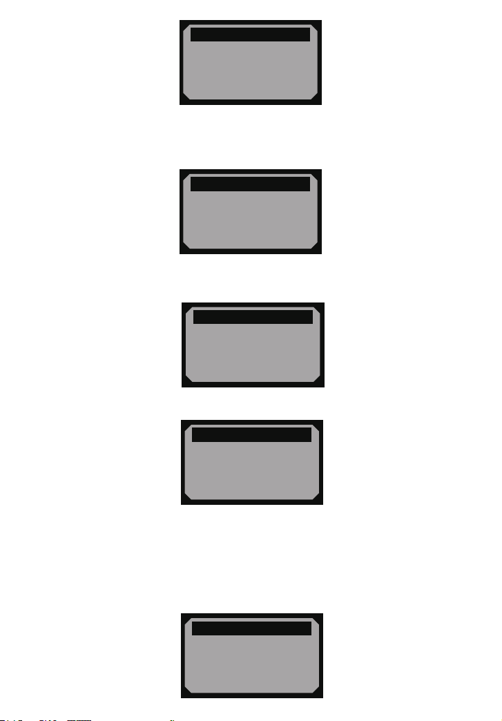
Control Module
= = = = = = = = = = =1/3
►
Engine
Module $A4
Exit
• Use SCROLL button to select a module, and press ENTER/EXIT button.
3) Wait a few seconds while the code reader reads vehicle information.
Vehicle Info.
= = = = = = = = = = = = =
Reading Info…
- Please Wait -
4) From Vehicle Info. menu, use SCROLL button to select an available items to view and
press ENTER/EXIT button.
Vehicle Info.
= = = = = = = = = = = =1/4
►
Vehicle ID Number
Calibration ID
Cal. Verif. Number
Exit
5) View retrieved vehicle information on the screen.
Vehicle ID Number
= = = = = = = = = = = = =
VIN:
2HGES16684H907941
6) Press ENTER/EXIT to return to previous menu.
4.6 Exiting OBDII Test
1) To exit OBDII test, use SCROLL button to select Exit from Diagnostic Menu and press
ENTER/EXIT button.
Diagnostic Menu
= = = = = = = = = = = =5/6
5) Vehicle Info.
►
6) Exit
- 16 -
Page 19

2) A warning message comes up asking your conrmation.
= = = = = = = = = = = = =
Exit Test
Exit OBDII Test!
Are you sure?
Yes
No
3) If you do want to exit OBDII test, press ENTER/EXIT button.
• If you do not want to exit, use SCROLL button the select NO and press ENTER/EXIT
button to return.
- 17 -
Page 20

Warranty
1-Year Warranty from date of purchase covering
manufacturing defects: hassle-free replacement
Website
www.veepeak.com
Scan to contact our
Email customer support
|
SMART YOUR LIFE
We hope you never have the need, but if you do, our
service is friendly and hassle-free
Contact Us At:
Made In China
 Loading...