

Page 1
Rep lac em e n t I n st ru ct i o n s
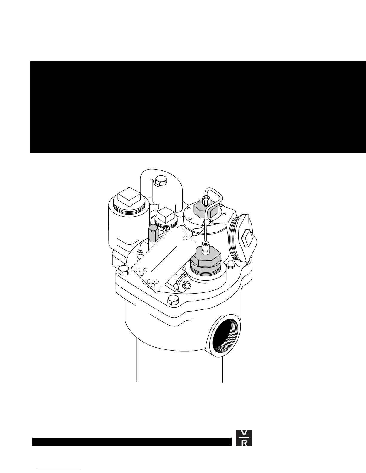
WPLLD Transducer
Replacement I nstru ct ions
Manual Number 577013-710, Revision A
WARNING
THE SUBMERGED PUMP SYSTEM SUPPLYING THE
DISPENSERS MAY TURN ON UNEXPECTEDLY TO
PERFORM A LINE LEAK TEST. THIS MAY RESULT
IN FUEL SPRAYING DURING DISPENSER, PRODUCT
LINE, LEAK DETECTOR OR STP SERVICE.
1. CLOSE AFFECTED DISPENSER SHEAR VALVE AND TEST
PERFORM THE FOLLOWING BEFORE BEGINNING SERVICE:
FOR PROPER SHUTOFF OF THE VALVE IF PERFORMING
DISPENSER HYDRAULIC SERVICE.
2. REMOVE POWER TO THE SUBMERGED PUMP (STP) AND
TO LLD-300 AND LINE LEAK DETECTOR SYSTEM.
3. WEAR EYE PROTECTION.
4. COLLECT FUEL IN APPROVED CONTAINERS.
DO NOT CONTAMINATE ENVIRONMENT.
TO ORDER TAGS - USE PART NO. 329801-00X
VEEDER-ROOT
Environmental Products
Page 2

Notice
Veeder-Root makes no warranty of any kind with regard to this publication,
including, but not limited to, the implied warranties of merchantability and fitness
for a particular purpose.
Veeder-Root shall not be liable for errors contained herein or for incidental or
consequential damages in connection with the furnishing, performance, or use of
this publication.
This publication contains proprietary information which is protected by copyright.
All rights reserved. No part of this publication may be photocopied, reproduced,
or translated to another language without the prior written consent of Veeder-Root.
The information contained in this publication is subject to change without notice.
Veeder-Root 1998. All rights reserved.
Page 3

Contents
Introduction
Safety Symbols .............................................................................................1
Warnings and Important Not es . . .. ...... . .... ..... .. .................... ... .. .................... ...2
Damage Claims .................... ..... .. .................... ... .... ..... .. ...... . ...... ... .... ............2
Replacing The WPLLD Sensor
Checking the Functio nal Element Orif ice
(For Red Jacket Pumps) .........................................................................3
WPLLD Sensor Removal......................................................................... 4
WPLLD Sensor Installation......................................................................4
Checking STPs for leaks ...............................................................................6
i
Page 4

Figures
Contents
Figure 1. Disabling the Functional Element ........................................... 4
Figure 2. Connecting WPLLD Sensor To Pump .................................... 5
ii
Page 5

Int roduction
This manual covers Transducer Replacement Instructions for Veeder-Root Wireless
Pressurized Line Leak Detection (WPLLD) Systems.
Safety Symbo ls
The following safety symbols may be used throughout this manual to alert you to
important safety hazards and precautions.
Explosive
Fuels and their vapors are extremely explosive if ignited.
Flammable
Fuels and their vapors are extremely flammable.
Electricity
High voltage exists in, and is supplied to, the device. A potential shock hazard exists.
OFF
Turn Power Off
Live power to a device creates a potential shock hazard. Always turn power off to the
device and associated accessories when servicing the unit.
No Power Tools
Sparks from power tools (such as drills) can ignite fuels and their vapors.
Use Safety Barricades
Unauthorized people or vehicles in the work area are dangerous. Always use safety
cones or barricades, safety tape, and your vehicle to block the work area.
Read All Related Manuals
Knowledge of all related procedures before you begin work is important. Read and
understand all manuals thoroughly. If you do not understand a procedure, ask someone
who does.
1
Page 6

Warnings and Important Notes
Warnings and Important Notes
Introduction
WARNING
This product is to be installed in syste ms operating near locations
where highly combustible fuels or vapors may be present.
Fire or explosion resulting in serious injury or death could result if the
equipment is improper ly in stall ed or modi fi ed. Ser iou s conta minat ion
of the environment may also occur.
1. Read and follow all instructions in this manual, including all
safety warnings.
2. Comply with all applicable codes including: the National
Electrical Code; federal , stat e, and local codes; and other
applicable safety codes.
3. Do not alter or modify any compon ent or substitute components
in this k it.
4. Do not use this component for other systems aside from the
WPLLD. Install console only as described in this manual.
5. The WPLLD must be installed and operated in an indo or location.
Damage Claims
1. Thoroughly examine all components and units as soon as received. If damaged,
write a complete and detailed description of the damage on the face of the freight
bill. The carrier's agent must verify the inspection and sign the description.
2. Immediately notify the delivering carrier of damage or loss. This notification may
be given either in person or by telephone. Written confirmation must be mailed
within 48 hours. Railroads and motor carriers are reluctant to make adjustments
for damaged merchandise unless inspected and reported promptly.
3. Risk of loss, or damage to merchandise remains with the buyer. It is the buyer's
responsibility to file a claim with the carrier involved.
4. Immediately advise your Veeder-Root representative, distributor, or the factory so
that we may assist you.
2
Page 7

Re plac i ng Th e WPL LD Sen so r
WARNING
This equipme nt uses leth al voltages and atta ches to acces sor y
components which operate in areas where flammable liquids and
vapors may be present.
Serious injury or death from shock, explosion, or fire may result if
power is on during instal l ati on and t he device is improp erly inst al led .
When installing this product:
1. Read and understand all instructions.
OFF
2. Turn OFF power to the console and submersible pumps during
installation.
3. Use only Veeder-R oot suppl ied service parts to avoid
compromising saf ety.
4. Wiring must comply with all applicable requirements of the
National Electrical Code; federal, state, and local codes; and any
other safety codes.
5. To protect yourself and others from being struck by vehicles,
block off your work area during installation or service.
Checking the Functional Elem ent Orifice
(For Red Jacket Pumps)
Impor tant ☞ If you are using an FE Petro pump, skip this section.
Remove the six slot-head screws from the functional element [Figure 1 on page 4].
1.
Visually verify that the orifice is free from debris and that the spring has been
2.
removed.
Carefully reassemble the functional element. Be sure that all gasketed surfaces are
3.
free from debris when reinstalling.
3
Page 8
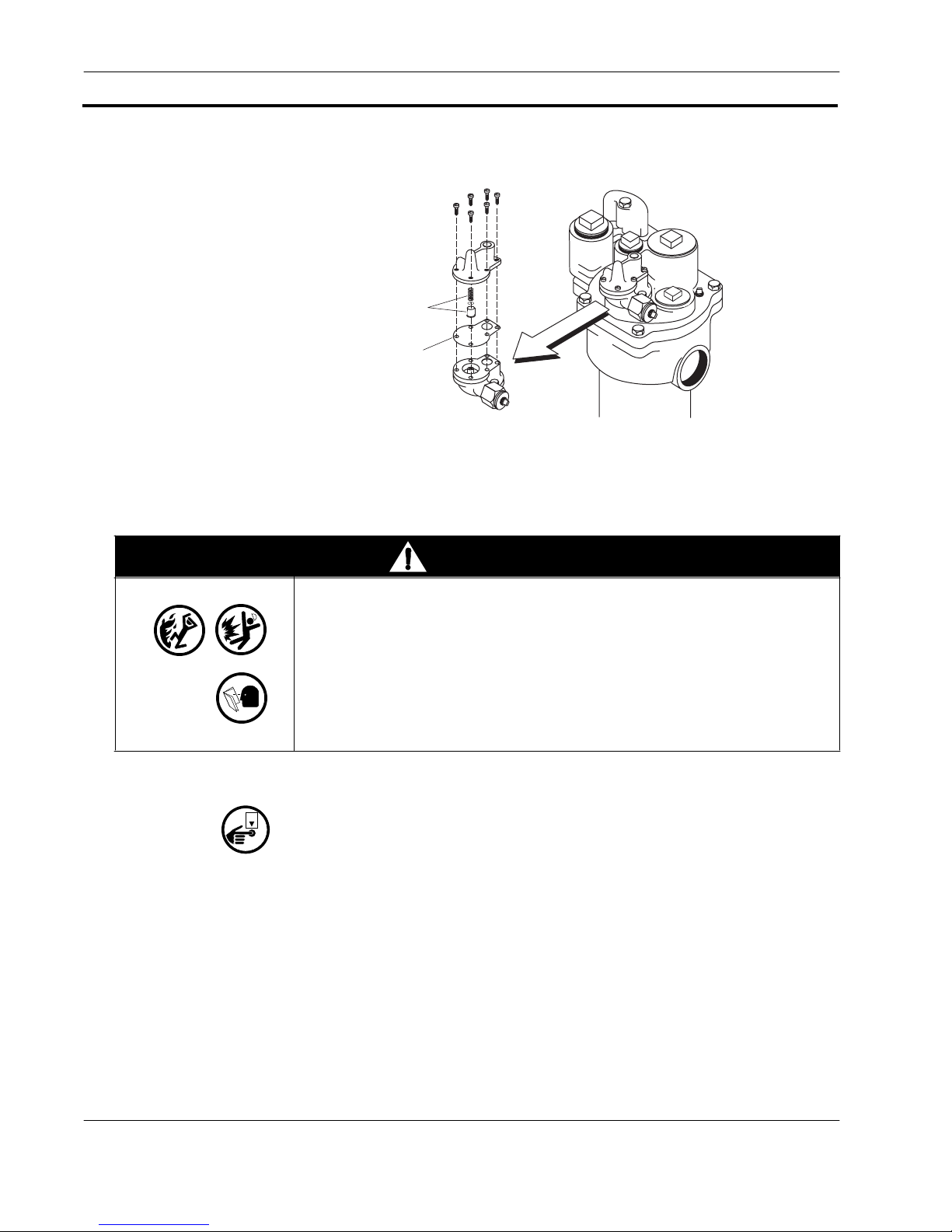
Checking the Functional Element Orif ice ( For Red Jacket Pum ps)
Remove
spring/
piston
assembly
Rubber
diaphragm
Red Jacket Pump With Older Functional Element
Figure 1. Disa bling the Functi onal Elem ent
Replacing The WPLLD Sensor
slld\frms2rj.eps
WARNING
This system contai ns haz ardous fu els.
If the functional element leaks, serious injury or death from fire or
explosion, or environmental contamination may result.
When reinstalli ng:
1. Follow instructions completely.
2. Check for leaks after the system is pressurized.
WPLLD Sensor Removal
OFF
1. Ensure power to the STP is turned OFF.
2. Disconnect the sensing line from the WPLLD sensor.
3. Remove the capacitor cover bracket from the WPLLD sensor and set it (and
pump capacitor cover) aside for reinstallation.
4. Unscrew the WPLLD sensor from the pump.
5. Remove the plastic shield from the capacitor housing and disconnect the sensor
wires from the pump wires.
4
Page 9

Replacing The WPLLD Sensor
WPLLD Sensor Installation
1. Remove the protective plastic cap from the WPLLD sensor.
2. If the sensor is being installed at altitudes above 2,000 feet, open the vent screw at
3. Retighten the vent screw securely to prevent water from entering. (Failure to
O-ring from
installation kit
Checking the Functional Element Orif ice ( For Red Jacket Pum ps)
least two turns, but not more than three turns, to vent any internal pressure.
(WPLLD sensors are equipped with a vent screw to equalize internal pressure.)
release internal pressure in the WPLLD sensor at altitudes above 2,000 feet could
cause inaccurate pressure readings and false line leak alarms.)
Wireless line leak sensor
shown upside down and
resting on pump
Vent screw - If you are installing
this sensor above an altitude of
2000 feet you must loosen this
screw (2 - 3 turns CCW) to
release any internal pressure,
and then retighten the screw.
Cut the black wire from
the power source to the capacitor
and strip each end to expose
1/2-inch of bare wire. Twist
the wire nut over the two ends
of the black wire you just cut
and stripped and the already
stripped end of one of the black
wires from the sensor.
Red wire from
motor to capacitor
(Leave as is)
Bleed resistor
Motor capacitor
shown removed
from storage well
Figure 2. Connecting WPLLD Sensor To Pump
slld\wscpwir.eps
Cut the orange wire (FE Petro
pumps) or the yellow wire
(Red Jacket pumps) running
through the motor capacitor
storage well and strip each end
to expose 1/2-inch of bare
wire. Twist the wire nut over the
two ends of the colored wire
you just cut and stripped and
the already stripped end of one
of the black wires from the
Wireless Line Leak Sensor.
5
Page 10

Checking STPs for leaks
Replacing The WPLLD Sensor
4. Follow the instructions in Figure 2 (above) to connect the WPLLD sensor to the
pump.
5. Replace the shield into the capacitor housing with open side up. Hold the shield at
an angle and place notched tab into the compartment first. Guide the two wires
from the WPLLD sensor into the notch on the shield, leaving as much slack in the
wires as possible above the shield (this will prevent stressing them when the
WPLLD sensor is threaded into the pump).
6. Lightly lubricate the O-ring on the WPLLD sensor with mineral oil or other
suitable lubricant.
7. Rotate the sensor about three turns counterclockwise, then screw the Wireless
Line Leak Sensor into the pump compartment and tighten it securely.
8. Reconnect the sensing line to the WPLLD sensor and tighten it securely.
9. With the two 6-32 x 0.375” screws provided, attach the capacitor cover bracket
(removed from the original WPLLD sensor) to the top of the new WPLLD sensor.
Snap the capacitor cover into the bracket.
Checkin g STPs for leaks
After connecting all of the sensors, apply power to each pump and check for leaks.
Verify that the functional element, sensing lines, and check valve threads into each
pump are not leaking. Product leakage can create serious environmental and safety
hazards.
❑
OFF
Tighten any leaking fittings until the leak is stopped. Be careful not to overtighten
and strip the threads. If the leak cannot be stopped, turn OFF power to the pump
and check the fitting for thread damage or improper sealing.
❑
Replace or reseal the fitting(s) as required.
6
Page 11

Page 12

Sales Offices
Veeder-Root has offices around th e world to serve you .
Headquarters
Veeder-Root Company
125 Powder Forest Drive
Simsbury, CT 06070-7684 U.S.A.
(860) 651-2700 FAX: (860) 651-2719
England
Veeder-Root Environmental Systems Limited
Hydrex House, Garden Road
Richmond, Surrey TW9 4NR ENGLAND
44-181-392-1355
Brazil
Veeder-Root do BRASIL
Rua ado Benatti, 92
Caixa Postal 8343
01051 Sao Paulo BRAZIL
55-11-861-2155
Germany
Veeder-Root GmbH
Uhlandstrasse 49
D-78554 Aldingen GERMANY
49 (0)7424 89285
France
Veeder-Root SARL
ZI des Mardelles
94-106 rue Blaise Pascal
93600 Aulnay-sous-Bois FRANCE
33 (0)1 4879 5599
Canada
Veeder-Root Canada
151 Superior Boulevard, Suite 24
Mississauga, Ontario, L5T 2L1 CANADA
905-670-2755
Singapore
Veeder-Root Singapore
#2 Kallang Pudding Road
#06-16 Mactech Industrial Building
SINGAPORE 1334
(65) 745-0368 FAX: (65) 745-0636
Mexico
Veeder-Root Mexico
Prado de las Camelias
No. 4483-4
Prados Tepeyac C.P. 45500
Zapopan, Jal., MEXICO
(52) 36-47-3750
577013-710, Revision A
VEEDER-ROOT
Environmental Products
 Loading...